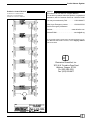
1
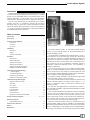
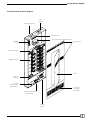
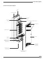
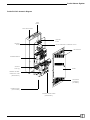
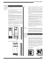
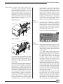
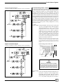
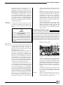
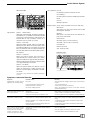
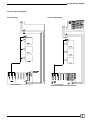
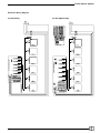
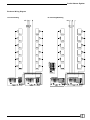
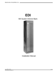
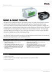
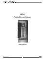
Prolite Dimmer System EDI Prolite Dimmer System Users Manual 070-0550 Revision 6, January, 1999 ©1998, Electronics Diversified, Inc. 1 Prolite Dimmer System Introduction Description This Manual is supplied with your Prolite Dimmer System. Copies of this manual may be obtained from the factory for a nominal charge. It is recommended that you copy those portions of this manual applicable to your present use in the installation, maintenance or repair and preserve the original in a safe place. No part of this Manual may be reproduced by any means, graphic, electronic, or mechanical, including photocopying, recording, taping, or information storage and retrieval systems, without the express written permission of Electronics Diversified, Inc., except in connection with installation, repair and maintenance of installed Prolite Dimmer Systems. Table of Contents Introduction . . . . . . . . . . . . . . . . . . . . . . . . . . . . . . . . . . . . . . . . 2 Description . . . . . . . . . . . . . . . . . . . . . . . . . . . . . . . . . . . . . . . . . 2 Prolite Isometric Diagram: PLS-DC12 . . . . . . . . . . . . . . . . . . . . . . . . . . . . . . . . . . . . . . 3 PLJ-DC6 . . . . . . . . . . . . . . . . . . . . . . . . . . . . . . . . . . . . . . . . 4 PLJ-DC3 . . . . . . . . . . . . . . . . . . . . . . . . . . . . . . . . . . . . . . . . 5 PLS-DC12 Senior Installation: Mounting . . . . . . . . . . . . . . . . . . . . . . . . . . . . . . . . . . . . . . . 6 Wiring . . . . . . . . . . . . . . . . . . . . . . . . . . . . . . . . . . . . . . . . . . 6 Power Consumption . . . . . . . . . . . . . . . . . . . . . . . . . . . . . . 6 PLJ-DC6 Junior PLJ-DC3 Mini The Prolite Dimmer System an extremely versatile dimming system It is the compact solution for advanced architectural or theatrical lighting systems. The Prolite series is available in three standard sizes. The PLJDC3 (referred to as a Prolite Mini) may contain up to three Quad 1.8k, Dual 2.4k, Dual 3.6k, or Single 6.0k dimming modules. Any combination of modules is permitted. The maximum number of dimming circuits in a PLJ-DC3 is twelve. A PLJ-DC6 (Prolite Junior) may contain up to six of any combination of modules, and has a maximum of twenty-four dimming circuits. Any combination of modules is permitted. The PLS-DC12 (Prolite Senior) uses a larger dimming module which is not interchangeable with those used in the Prolite Mini/ Junior. The PLS-DC12 may contain up to twelve Quad 2.4k, Dual 2.4k, Dual 3.6k, or Single 6.0k dimming modules, in any combination, with a maximum of forty-eight dimming circuits. The dimmer cabinet resembles a normal circuit breaker panel and can be easily surface or recess mounted. The 1020 controller interface card (located at the bottom of the dimmer cabinet) translates an analog control voltage (0 - +10 VDC) to a firing pulse which is connected to the input of the dimming module. The optional 1050 digital interface card allows the system to become DMX compatible, supporting RS 485 data links for Twilite 9 communications. Each controller card will accommodate up to twenty-four dimming circuits. The PLJ-DC3 (Mini) and the PLJ-DC6 (Junior) use one controller card each ( the Mini, with a maximum of twelve circuits, uses one-half of the circuitry on the controller card), while the PLSDC12 (Senior) uses two cards: one for circuits one through twentyfour, and the other for twenty-five through forty-eight. While the standard controller card is for incandescent or low voltage lighting, adapter cards are available for standard ballast fluorescent, dimming ballast fluorescent, and neon/cold cathode fixtures. Additionally, non-dim adapter cards controlled either by the analog control signal, or by momentary switches are available. Operation: Input Power . . . . . . . . . . . . . . . . . . . . . . . . . . . . . . . . . . . . . 6 Dimmer Modules . . . . . . . . . . . . . . . . . . . . . . . . . . . . . . . . . 7 Analog Control Input . . . . . . . . . . . . . . . . . . . . . . . . . . . . . . 7 Analog Control Board . . . . . . . . . . . . . . . . . . . . . . . . . . . . . 7 Analog Control Block Diagram . . . . . . . . . . . . . . . . . . . . . . 8 Digital Control Block Diagram . . . . . . . . . . . . . . . . . . . . . . . 8 Troubleshooting Guide-Analog: +15VDC Supply . . . . . . . . . . . . . . . . . . . . . . . . . . . . . . . . . . 8 Control Voltage Input . . . . . . . . . . . . . . . . . . . . . . . . . . . . . . 8 Checking Load Circuits . . . . . . . . . . . . . . . . . . . . . . . . . . . . 9 Dimmer Control Fault Isolation . . . . . . . . . . . . . . . . . . . . . . 9 Troubleshooting Guide-Digital: Digital Control Card 1050 . . . . . . . . . . . . . . . . . . . . . . . . . . 9 Soft Start . . . . . . . . . . . . . . . . . . . . . . . . . . . . . . . . . . . . . . . 9 CPU 1040 . . . . . . . . . . . . . . . . . . . . . . . . . . . . . . . . . . . . . . 10 Dip Switches . . . . . . . . . . . . . . . . . . . . . . . . . . . . . . . . . . . 10 LED Operation . . . . . . . . . . . . . . . . . . . . . . . . . . . . . . . . . . . 10 Remote Input . . . . . . . . . . . . . . . . . . . . . . . . . . . . . . . . . . . 10 670-1043 Card . . . . . . . . . . . . . . . . . . . . . . . . . . . . . . . . . . 10 Symptons, Causes and Remedies . . . . . . . . . . . . . . . . . . . 10 Enclosure Wiring Diagrams . . . . . . . . . . . . . . . . . . . . . 11, 12, 13 Replacement Parts: Replaceable Parts List . . . . . . . . . . . . . . . . . . . . . . . . . . . . 14 Prolite Control Harness . . . . . . . . . . . . . . . . . . . . . . . . . . . . . . 15 Service . . . . . . . . . . . . . . . . . . . . . . . . . . . . . . . . . . . . . . . . . . . . 15 Registration . . . . . . . . . . . . . . . . . . . . . . . . . . . . . . . . . . . . . . . 16 2 Prolite Dimmer System Prolite PLS-DC12 Isometric Diagram LOAD ENTRY MAIN FEED ENTRY GROUND BUSS CIRCUIT BREAKER / TERMINAL BLOCK NEUTRAL BUSS AIR EXHAUST COOLING BARRIER DIMMER MODULE DOOR COOLING FANS (4) DIMMER CONTROL CARD (REMOVABLE) AIR INTAKE ASSEMBLY (FILTERED) CONTROL CONNECTIONS (REMOVABLE) CONTROL ENTRY 3 Prolite Dimmer System Prolite PLJ-DC6 Isometric Diagram LOAD ENTRY MAIN FEED ENTRY GROUND BUSS NEUTRAL BUSS CIRCUIT BREAKER / TERMINAL BLOCK AIR EXHAUST DIMMER MODULE DOOR COOLING FANS (2) DIMMER CONTROL INTERFACE CARD (REMOVABLE) AIR INTAKE ASSEMBLY (FILTERED) CONTROL ENTRY (NOT SHOWN) CONTROL CONNECTIONS (REMOVABLE) 4 Prolite Dimmer System Prolite PLJ-DC3 Isometric Diagram LOAD ENTRY MAIN FEED ENTRY GROUND BUSS NEUTRAL BUSS CIRCUIT BREAKER / TERMINAL BLOCK AIR EXHAUST DIMMER MODULE COOLING FANS (2) DOOR DIMMER CONTROL INTERFACE CARD (REMOVABLE) AIR INTAKE ASSEMBLY (FILTERED) CONTROL ENTRY (NOT SHOWN) CONTROL CONNECTIONS (REMOVABLE) 5 Prolite Dimmer System Installation The only spacing requirements for access and working space is that required by national and local electrical codes for dead front switchboards. Mounting: Wiring: The Prolite Dimmer System may be ordered for surface or recessed mounting. Surface mounting the Prolite Dimmer System is accomplished utilizing securing devices through the ¼" mounting holes in each corner of the enclosures. The PLJ-D3 AND PLJ-D6 units may be mounted on any load-bearing wall that is at least 4 inches thick. Recessed mounting of the unit between 16-inch centered wall studs may be accomplished in the same manner as surface mounting or with the fastening devices through ¼" holes in four supplied brackets into the studs. The PLS-D12 unit may be mounted on any loadbearing wall that is at least 6 inches thick. Recessed mounting of the unit between 32-inch centered wall studs may be accomplished in the same manner as the PLJ-D3 and PLJ-D6. PLJ-DC3, PLJ-DC6 Mounting Dimensions Knockouts to accommodate up to 13/8" conduit fittings are provided on the top and bottom of the enclosure (refer to Page 3, 4, 5 for specific locations). The Prolite series enclosure has been designed for main power feed entry in the upper left corner and all load wiring exiting through conduits on the right top. All control wiring enters the enclosure at the bottom right corner of the enclosure. The Prolite Dimmer System PLS-DC12 is designed for a three-phase main service of 320A, or a single-phase service of 480A. The PLJ-DC6 is designed for a three-phase main service of 125A, or a single-phase service of 150A. The PLJ-DC3 is designed for a three-phase main service of 60A, or a single-phase service of 100A. Due to the nature of dimming systems, it is recommended the neutral conductor be sized to 125% of the highest connected phase load. The output load connections may be made to a terminal block or a breaker lug and be from 15A to 50A depending on the dimmer module. Use of lighting circuits in excess of 20A should conform with local and national codes. Power Consumption: The Prolite Dimmer System has a power dissipation of approximately 38.0 BTU plus 100 BTU for each 1000 watts of connected load. The equation for determining the power dissipation for the Prolite dimmer system with all dimmers at full is as follows: BTU = 38 + 100 x (Kw of connected Load) Operation The Prolite Dimmer System may be divided into three main elements: main power feed input, dimmer modules and dimmer control. Input Power: The input power element is dictated by the configuration the customer desires. The main input power may connect to a main feed block or a main breaker. The input power may be 120/240VAC single- phase three wire plus ground or 120/ 208VAC three- phase four-wire plus ground; input power may be 50 or 60 Hertz. From the input main feed element, power branches off to the dimmer modules and to the dimmer control element of the Prolite Dimmer System. The dimmer control element utilizes the power to generate various control voltages within the system. PLS-DC12 Mounting Dimensions Main Power Feed: PLJ-DC3, DC6 PLS-DC12 Neutral 6 Ground Prolite Dimmer System Dimmer Modules: Each dimmer module contains a primary or input circuit breaker, output load breakers or terminals, an over-temperature thermal switch, one or more Solid State Relay (SSR) devices, one or more device connection printed circuit boards, and, depending on the load type for which the dimmer is designed, it may or may not contain chokes. The primary circuit breaker protects the SSR device and the load circuit, (on modules having terminal outputs), against over-current. thermal switch is connected in series with the dimmer modules control supply voltage and will open in the event the module temperature exceeds the safe operating limit, thus shutting down the module until the temperature returns to a safe operating level. The device connection printed circuit boards are secured to the SSR devices, providing a convenient means of connecting the control harness to each module and routing the various control and signal voltages to their respective locations within the dimmer module. PLS-Q2/I (Typical) Analog Control Input: BRANCH CIRCUIT BREAKERS TERMINAL BLOCK THERMAL SENSOR LOCATION (NOT SHOWN) Control input varies depending on the options purchased. Basic 0 - +10VDC (1020) analog input wiring enters the bottom right corner of the dimmer system enclosure. The control circuitry common or return terminates on the Prolite Control Interface Card P10 or P11 pin 1. The control wire terminates on the appropriate P10 or P11 pin. Prolite 1020 Analog Control Interface Card P10 P11 HEAVY DUTY HEATSINK SILICON RECTIFIERS TOROIDAL CHOKES PLJ-Q1/I (Typical) TERMINAL BLOCK (NOT SHOWN) SILICON RECTIFIERS Analog Control Board: The dimmer control element provides the circuitry which generates the phasing necessary to cause the SSR devices to turn on at the appropriate time within the dimmers input power cycle allowing the desired dimming with the appropriate control voltage applied. A 0 - +10VDC control voltage is applied to the control signal conditioning circuitry where isolation, limiting and splitting takes place. Two signals exit the conditioning signal circuitry, one to activate the fan control and the other to the firing angle comparator. When the input control voltage exceeds approximately 1.2VDC, the fans turn on and remain on for about 45 seconds after the control input voltage falls below that level. The firing angle comparator circuit compares the applied control signal with a ramp wave and outputs a ground seeking pulse when the control voltage exceeds the ramp voltage; the output pulse remains low until the input power for the particular phase crosses zero. The output pulse width is determined by how far past zero crossing the control voltage exceeds the ramp voltage. The ramp generators produce a ramp wave voltage that repeats itself every time the input power waveform crosses zero. The ramps origination and termination points may be varied over a limited range through use of the High and Low Cal screwdriver adjustments; these adjustments will affect each of the dimmers on the respective phase. THERMAL SENSOR LOCATION (NOT SHOWN) BRANCH CIRCUIT BREAKERS HEAVY DUTY HEATSINK TOROIDAL CHOKES For modules with output breakers, the output breakers protect the load circuit as well as provide a means of connecting multiple load circuits to a single dimmer output so long as the total load current does not exceed the dimmer's primary breaker rating. The SSR device is the active element that performs the actual load circuit dimming. Each SSR device may contain one or two separately controlled load dimming circuits. Quantity of dimming circuits depends on load current and supply voltage. The load dimming circuit within the SSR device consists of two Silicon Controlled Rectifiers in a back-toback configuration connected to control circuitry via optical isolators. A number of resistors and capacitors have been added to the load circuit in each SSR device in various configurations. This prevents false firing due to transient voltages caused by reactive loads, and to protect the Silicon Controlled Rectifiers. The over-temperature 7 Prolite Dimmer System Analog Control Block Diagram PLJ-DC3 (1 board); PLJ-DC6 (1 board); PLS-DC12 (2 boards) Troubleshooting Guide - Analog While the Prolite System is generally trouble-free, this section will provide information necessary to isolate and pinpoint problem areas. Isolating the problem in a Prolite dimming system can usually be done with basic tools and a multimeter. A technical background is not necessary, but having and knowing how to operate a multimeter will be helpful. With the front door assembly and circuit breaker covers removed, look for the obvious; connectors unplugged, circuit breakers turned Off, fuses blown or missing. For now, we will assume all loads are incandescent lamps. Verify the presence of voltage at the power input block or breaker. Check for the proper control voltages coming into P10 and P11. Both P10-1 and P11-1 are control ground, usually designated on factory drawings as GND. +15VDC Supply Voltage: Using a multimeter, select the volts function and the 20 (or next higher) range. With the negative (black) meter lead to P10-1 (or P11-1), the positive (red) lead can be used to check the +15 volt supply at P10-2 (or P11-2). If this is not present, check the fuse (F2) furthest left on the circuit board. There should be +l5 volts on both ends of the fuse. If voltage is present only on one end, the fuse is defective. If voltage is not present on either end, check to see that the green phase indicator lights on the circuit board are on. (NOTE: In a three-phase system, all three indicator lights should be lit; however, in a single-phase system, only the first and third lights should be lit. If they are not illuminated, check the three fuses toward the bottom of the circuit board.) Prolite Analog Control Card 1020 Digital Control Block Diagram PLJ-DC3 (1 board); PLJ-DC6 (1 board); PLS-DC12 (2 boards) + 15 VOLT FUSE (2 AMP) PHASE INDICATOR LIGHTS P 10 P 11 P 10-1 1 AMP FUSES P 11-1 P 12 WARNING: These fuses are connected to line voltage! If the +15 volt fuse blows when replaced, unplug P10 and P11, then replace the fuse. If the fuse does not blow when P10 and P11 are disconnected but blows when P10 or P11 are plugged in, the problem is not with the Prolite, but rather with the controller(s), or contractor-installed wiring. Control Voltage Input: If tests up to this point have been satisfactory, it is important to check the control voltages before proceeding with the Prolite. With the negative (black) multimeter lead still connected to P10-1 or P11-1, the positive (red) probe can be used to 8 Prolite Dimmer System check the incoming control voltages on P10-3 through P10-14, and P11-3 through P11-14. Depending on the system, not all of these control inputs need to be used (Refer to the factory Field Wiring Diagram for this information). The correct control voltages are approximately +10 volts for the Full On when the slider is at ten (all the way up), to around 0.4 volts for Off when the slider is at zero (all the way down). Readings significantly different than those given here would probably be caused by a defective controller, or contractorinstalled wiring problems. cubes connected to loads, connect one end of the wire from the previous check to GND (P10-1 or P11-1), When the other end is touched to control output connectors (P1 through P6) on pins 7 thru 10, the corresponding dimmer should go to full intensity, and remains so as long as this connection is maintained. If this happens, the corresponding dimmer module is okay. If not, the power cube could be defective, or more likely, a connector (P1 through P6), or the control connections at the dimmer modules is loose. When measuring dimmer output voltage, a load must be connected to the output to obtain a valid measurement. A dimmer output with no load will measure a significant voltage regardless of the control input due to SCR leakage causing the output to float. Checking Load Circuits: To check each load circuit, disconnect the load wire at the circuit breaker and momentarily connect to a 120 volt circuit breaker protected power source. Troubleshooting Guide - Digital When a 1050 card is inserted in the control bus, the system becomes DMX compatible. Any DMX console has access to Prolite dimmers. If two consoles address the Prolite system with two DMX cards. Prolite operates on a "highest takes precedence" basis and both consoles have access to the Prolite dimmers. The DMX card also supports RS 485 data link for Twilite 9 communications. The DMX card also provides an Auto-Hold feature which will hold the last valid signal indefinitely when the signal is interrupted or lost. WARNING: DO NOT, under any circumstances, use the power input block. This power source is capable of inflicting severe damage in the event of a line-to-neutral or line-to-earth ground source. If all is correct, the lamps of each circuit will illuminate when power is applied. A number of problems could prevent the circuit from functioning. Check for missing or loose lamps, fixtures not plugged in, open connections in junction boxes, and the neutral not being connected. Digital Control Card 1050 CPU 670-1040 Dimmer Control Fault Isolation: In the event of a lamp which is stuck On and cannot be dimmed with the controller, disconnect the corresponding control output connector (P1 through P6) at the circuit board (see Enclosure Wiring Diagram, pgs 9, 10,11). If the lamp stays on, the power cube to that circuit is defective, and will need to be replaced. If the lamp goes off, reconnect P1 through P6, then disconnect control input plugs P10 and P11. If the lamp goes out, the Prolite dimmer is receiving a control voltage, and is responding correctly. If disconnecting the corresponding control output connector turns off the light but disconnecting P10 and P11 does not, the circuit board is defective, and will need to be repaired or replaced. To check the Prolite dimmer without the use of a controller, disconnect control input plugs P10 and P11. Using twelve-inch piece of wire with stripped ends, connect one end to the +15 volt supply at P10-2 or P11-2. When the other end is touched to a control input connection (P10-3 through P10-14 and P11-3 through P11-4), the corresponding dimmer should go to full intensity, and remain so as long as +15 volts is being applied to the control input connection. As mentioned earlier, any particular system may or may not use all of the control input connections. To check the power +15 VOLT FUSE (2 AMP) INPUT CARD 670-1043 BYPASS CARDS PHASE INDICATOR LIGHTS 1 AMP FUSE P 12 There is no troubleshooting on a DMX 1050 control card. The 1050 card acts as a motherboard for various CPU Control cards that make up the unique capabilities of the Prolite. When the phase indicator lights are glowing steadily, there is a good power signal from the components. If the lights are flashing, there is a loss of power somewhere in the system. The standard arrangement in a 1050 card consists of a CPU 1040 card, two bypass cards, and an input card (1043) that allows both analog and digital signals. Soft Start: 9 Whenever the DMX signal becomes active, the dimmer outputs are soft-started from 0% to the current levels in about eight seconds. Prolite Dimmer System CPU Card 1040 INPUT POWER LED LED Operation: LED Off: No DMX input present. Dimmers are Off. U11 LED Flashing: No DMX present. Dimmers holding last dimmer levels. LED On: DMX input present. Remote Inputs: (These inputs are made on the 670-1043 card). DMX Active: A29 (Active Low). This output is low when a valid DMX signal is received. DIP SWITCHES Dip Switches: Switch 1 - Reload Patch: When ON, (switch closed), the patch stored in the Serial ROM (U11) is loaded over the internal RAM on power up or reset. When OFF (switch open), the internal RAM is only overwritten if there is a checksum error on power up or reset. Switch 2 - Fast Fade: When ON (switch closed), there is no hold when DMX input is lost. When OFF (switch open), there is a hold after DMX is lost. Use Switch 3 to set hold time. The dimmers fade out in approximately five seconds after DMX Is lost and the hold time, if any, has expired. Blackout: B29 (Active Low). When active, the dimmer outputs are forced to black. DMX INPUTS: B31-DMX- (pin 2 on XLR connector). A31-DMX+ (pin 3 on XLR connector). HHR INPUTS: B300-TX (to HHR) A30 - RX (from HHR) Card 670-1043 REMOTE PROGRAM INPUTS Switch 3 - Hold Time: When ON (switch closed), the hold time is approximately five minutes. When OFF (switch open), the hold time is approximately 30 minutes. After the hold time has expired, the dimmers fade out is approximately five seconds. Switch 4 - EDI Mode: When ON (switch closed), the dimmer is in EDI mode, for interfacing to a Twilite 9 system only. When OFF (switch open), the dimmer is in DMX512 mode. DMX ACCESSORIES INPUT ANALOG INPUT (P-10, P11) (This switch is only read when the board is powered up or reset). Symptoms, Causes and Remedies Symptom Possible Cause Remedy System dead, no lights come on, regardless of controller setting. No power. Verify presence of voltage at power input circuit breakers, if used. Turn circuit breakers on. Check fuses on Prolite circuit board. Verify +15 volts at P10-2 or P11-2. If O.K. check controller and associated wiring. Load circuit breakers are turned off. Phase fuses blown or missing. No control voltages present. Some of the lights come on, but one or more will not. Open load. Loose control connector. Control input wiring incorrect at P10 or P11. Verify load by connecting to known good circuit. Check all control connectors on dimmer modules. Check wiring at P10 or P11 using factory supplied drawings. Lights blink, pulsate, or flicker. Control wires run in same conduit as power wires. Move control wires to a conduit containing only Class II wiring. Contact factory. Have fixture manufacturer and model number accessible. Contact factory. Have fixture manufacturer and model number accessible. Electronic ballasts or low voltage lamp fixtures are being used. Lamps with series diodes are being used, and only one polarity is on circuit. When on at "full" for ten minutes to an hour, one or more circuits will shut off for ten to twenty minutes, come back on, and continue to cycle in this manner. Intake and/or exhaust ports of dimmer cabinet are blocked. Fans are not running. 10 Remove obstruction. Verify fan power connectors to be secure. Check connectors and be sure fan blades turn freely. Prolite Dimmer System Enclosure Wiring Diagram PLJ-DC3 Analog PLJ DC3 Digital/Analog 11 Prolite Dimmer System Enclosure Wiring Diagram PLJ-DC6 Analog PLJ DC6 Digital/Analog 12 Prolite Dimmer System Enclosure Wiring Diagram PLJ DC12 Digital/Analog PLJ-DC12 Analog 13 Prolite Dimmer System Replacement Parts PLJ Replaceable Parts List Changes to EDI equipment are made to accommodate improved components as they become available, and to give you the benefit of the latest circuit improvements. To obtain replacement parts, call 1-(800)-547-2690 and ask for Customer Service. It is important to include the following information in your order: Part Number, Equipment type or Number, Serial Number, and original EDI System Drawing Number (As-built Drawing No.). EDI Number Description PLJ DC3/S/TB Cabinet: 975-2000 Enclosure PLJ-DC3/S/TB 105-0011 Latch/Lock Assembly 147-0013 Fan, 53CFM 3.62" SQ 115VAC 178-0001 Filter, Air PL-DC3 & 6 670-1020 24-Channel Control & Power Supply 670-1050 Prolite P. C. Ramps (Optional) PLJ DC6/S/TB Cabinet: 975-1000 Enclosure PLJ-DC6/S/TB 105-0011 Latch/Lock Assembly 147-0013 Fan, 53CFM 3.62" SQ 115VAC 178-0001 Filter, Air PL-DC3 & 6 670-1020 24-Channel Control & Power Supply 670-1050 Prolite P. C. Ramps (Optional) PLJ Dimming Modules: 020-6201 Dimmer PLJ-Q1/I 019-0046 D24 SSR Assembly Safety Cube 108-0030 Choke, 10A 260-0094 Heat Sensor, 180°F 261-2015 Breaker, 15A 020-6202 Dimmer PLJ-Q1/ND 019-0046 D24 SSR Assembly Safety Cube 260-0094 Heat Sensor, 180°F 261-2015 Breaker, 15A 020-6206 Module Dimmer PLJ-D2/I 019-0046 D40 SSR Assembly Safety Cube 108-0024 Choke, 20A 260-0094 Heat Sensor, 180°F 261-2020 Breaker, Double Pole, 20A 020-6207 Module Dimmer PLJ-D2/ND 019-0046 D40 SSR Assembly Safety Cube 260-0094 Heat Sensor, 180°F 261-2020 Breaker, Double Pole, 20A 020-6214 Module Dimmer PLJ-D2/I-HP 019-0046 D40 SSR Assembly Safety Cube 108-0024 Choke, 20A 260-0094 Heat Sensor, 180°F 261-2020 Breaker, Double Pole, 20A 020-6216 Module Dimmer PLJ-D3 019-0046 D40 SSR Assembly Safety Cube 260-0094 Heat Sensor, 180°F 260-0130 Breaker, 30A-1P 260-0119 Breaker, Double Pole, 20A 020-0261 Module Dimmer PLJ-6 019-0049 S80 SSR Assembly Safety cube 260-2050 Breaker, 50A-1P 260-3020 Breaker, Double Pole 20A Part Numbers Associated with Prolite Dimmer Controls Part Number 670-1020 670-1050 670-1051 670-1040 670-1041 670-1042 670-1043 671-1043 672-1043 673-1043 674-1043 675-1043 676-1043 677-1043 670-1044 670-1021 670-1025 670-1030 671-1025 670-1026 671-1021 670-1028 670-1034 Description Dimmer Control Board, Analog only Dimmer Control Board, Digital Interface, Input/Output, for CPU CPU card, Twilite 9 and DMX Worklight card Analog Patch card Input card, no Headers Input card, 1 CPU Input card, 2 CPU's Input card, 3 CPU's Input card, 1 CPU & Analog Input card, 2 CPU's & Analog Input card, 3 CPU's & Analog Input card, Analog only Bypass card Adapter card, standard ballast Adapter card, dimming ballast Adapter card, Advance Mark VII ballast Adapter card, neon/cold-cathode Adapter card, Non-Dim, +15 Adapter card, Non-Dim, +24 Adapter card, Non-Dim Analog Adapter card, Low voltage, Non-Dim PLS Replaceable Parts List EDI Number Description PLS-DC12/S/TB Cabinet: 975-0010 Enclosure PLS-DC12/S/TB 105-0011 Latch/Lock Assembly 147-0008 Fan, Axial, 100CFM 5.25" Sq., 117VAC 670-1020 24-Channel Control & Power Supply 670-1050 Prolite P. C. Ramps (Optional) 378-1008 Air filter PLS Dimming Modules: 020-6250 Module PLS-Q2/I 019-0046 D40 SSR Assembly Safety Cube 260-0094 Heat Sensor 180°F 261-2020 CB 20A-1P 020-6251 Module PLS-Q2/ND 019-0046 D40 SSR Assembly Safety Cube 260-0094 Heat Sensor 180°F 261-2020 CB 20A-1P 020-6255 Module PLS-D2/I 019-0046 D40 SSR Assembly Safety Cube 260-0094 Heat Sensor, 180°F 261-2020 CB 20A-1P 020-6260 Module PLS-D2/I-HP 019-0046 D40 SSR Assembly Safety Cube 260-0094 Heat Sensor, 180°F 261-2020 CB 20A-1P 020-6265 Module PLS-D3/I 019-0046 D40 SSR Assembly Safety Cube 260-0094 Heat Sensor, 180°F 260-2030 CB 30A-1P 260-3020 CB 20A Dual 020-6268 Module PLS-6/I 019-0049 D80 SSR Assembly Safety Cube 260-0094 Heat Sensor, 180°F 260-2050 CB 50A-1P 260-3020 CB 20A Dual PLJ & PLS Control Board Replaceable Parts List EDI Number Description 670-1020 24-Channel Control & Power Supply 120-0060 Xfmr 12.6VCT 1.2VA 120-0063 Xfmr 16VCT 24VA 148-0015 Relay, 5A SPDT 12VDC Coil 156-0120 Regulator, 15V 7815C 159-0015 Fuse, 8AG 1Amp 159-0017 Fuse, 2A 8AG PLJ & PLS Module Solid State Relay Parts List 14 EDI Number Description 019-0046 152-2025 670-9406 019-0049 152-2017 670-9411 D40 SSR Assembly Safety Cube SSR Dual 40A S/S Relay Connector Assembly S80 SSR Assembly SCR Pack 80A 400V S/S Relay Connector Assembly Prolite Dimmer System Prolite Jr. Control Harness Service As shown, PLJ-DC6 harness. Halve for PLJ-DC3 harness. Double for PLS-DC12 harness. EDI offers a 24 hour Service / Support Network. For technical questions about this product or operational assistance, ask for Customer Service at: 1-800-547-2690 You may communicate by FAX: . . . . . . . . . 1-503-629-9877 After Hours Emergency contact: . . . . . . . . 1-503-645-5533 Ask for Emergency Assistance. Internet: . . . . . . . . . . . . . . . . . . . . . . . . . www.edionline.com Internet E-Mail: . . . . . . . . . . . . . . . . . . . . . . . . . . [email protected] If your Prolite System needs repair, call 503-645-5533 for a Return Materials Authorization number, and a shipping address will be furnished. Electronics Diversified, Inc. 1675 N.W. Cornelius Pass Road Hillsboro, Oregon, 97124 Ph: (503) 645-5533 Fax: (503) 629-9877 15 Prolite Dimmer System Attention Prolite owners! Please return this registration card immediately. Your prompt attention to this matter will ensure your receiving updated technical information for this product as it becomes available. Please complete all information. Look for acknowledgment of your registration within 6-8 weeks. Name: _______________________________________________ Title: _________________________________________________ Facilityand/orCompany: _________________________________ ____________________________________________________________ Street Address: ________________________________________ ____________________________________________________________ ! CUT ALONG DOTTED LINE City: ___________________________ State: ____ Zip: ________ Phone: _______________________________________________ Fax: _________________________________________________ E-mail: ________________________________________________ Web site: ______________________________________________ Mail to: EDI User Manual Registration 1675 NW Cornelius Pass Road Hillsboro, Oregon 97124 or FAX to: (503) 629-9877 Revision 0, May 1998 16