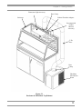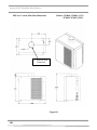
1
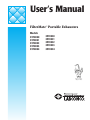
User’s Manual
FilterMate™ Portable Exhausters
Models
3970000
3970001
3970002
3970003
3970004
3970020
3970021
3970022
3970023
3970024
Labconco’s Mascot,
Labby the LABster
For more information, please contact us:
ExpotechUSA
10700 Rockley Road
Houston, Texas 77099
USA
281-496-0900 [voice]
281-496-0400 [fax]
E-mail: [email protected]
Website: www.ExpotechUSA.com
Labconco FilterMate™ Portable Exhausters Manual
Warranty
Labconco provides a warranty on all parts and factory workmanship. The warranty includes areas of
defective material and workmanship, provided such defect results from normal and proper use of the
equipment.
The warranty for all Labconco products will expire one year from date of installation or two years from
date of shipment from Labconco, whichever is sooner, except the following:
•
•
•
Purifier® Delta® Series Biological Safety Cabinets and PuriCare™ Animal Laboratory Research
Enclosures carry a three-year warranty from date of installation or four years from date of
shipment from Labconco, whichever is sooner.
Carts carry a lifetime warranty.
Glassware is not warranted from breakage when dropped or mishandled.
This limited warranty covers parts and labor, but not transportation and insurance charges. In the event of a
warranty claim, contact Labconco Corporation or the dealer who sold you the product. If the cause is
determined to be a manufacturing fault, the dealer or Labconco Corporation will repair or replace all
defective parts to restore the unit to operation. Under no circumstances shall Labconco Corporation be
liable for indirect, consequential, or special damages of any kind. This statement may be altered by a
specific published amendment. No individual has authorization to alter the provisions of this warranty
policy or its amendments. Lamps and filters are not covered by this warranty. Damage due to corrosion or
accidental breakage is also not covered.
Limitation of Liability
The disposal and/or emission of substances used in connection with this equipment may be governed by
various federal, state, or local regulations. All users of this equipment are required to become familiar with
any regulations that apply in the user’s area concerning the dumping of waste materials in or upon water,
land, or air and to comply with such regulations. Labconco Corporation is held harmless with respect to
user’s compliance with such regulations.
.
Part #3922700, Rev. A
ECO C573
TABLE OF CONTENTS
CHAPTER 1: INTRODUCTION
About This Manual
Typographical Conventions
1
3
4
CHAPTER 2: PREREQUISITES
Electrical Requirements
Ground Fault Interrupter
Exhaust Requirements for the FilterMate
Location and Preparation Requirements
Your Next Step
5
5
6
6
7
8
CHAPTER 3: GETTING STARTED
Unpacking Your FilterMate
Setting Up Your FilterMate
Initial Installation of HEPA Filters and Carbon Filters
Carbon Filters
Combination HEPA/Carbon Filters
Dual Carbon
Connect the Electrical Supply Source to FilterMate
Set the Face Velocity with Speed Control Adjustment
9
9
10
13
13
13
14
20
20
CHAPTER 4: USING YOUR FILTERMATE
Suitable Applications
Applications for the FilterMate
Definition of Terms
Appropriate Chemicals
Use of Chemical Carcinogens in the FilterMate
Acids Must not Be Used
Safety Precautions
HEPA FilterMate Equipped with HEPA Filter
Misapplications that could result in a Hazardous Situation
21
21
22
22
23
24
25
25
27
28
CHAPTER 5: MAINTAINING YOUR FILTERMATE
Monthly
Determination of when to Replace Carbon Filters
Determination of when to Replace HEPA Filters
Install New HEPA Filter with Bag-In/Bag-Out Procedure
FilterMate HEPA Filter Leak Test
Motorized Impeller Replacement
Speed Control Replacement
29
29
30
32
32
34
36
36
CHAPTER 6 MODIFYING YOUR FILTERMATE
Converting a Room Exhaust HEPA FilterMate to Outside
Exhaust
Converting a Combination HEPA/Carbon FilterMate to a
Dual Carbon FilterMate
Converting a HEPA FilterMate to a Combination
HEPA/Carbon FilterMate
37
37
38
38
CHAPTER 7 TROUBLESHOOTING YOUR FILTERMATE
39
APPENDIX A: FILTERMATE COMPONENT
AND REPLACEMENT PARTS
41
APPENDIX B: FILTERMATE SPECIFICATIONS
Electrical Specifications
Environmental conditions
Dimensions
Wiring Diagram
45
45
45
47
49
APPENDIX C: FILTERMATE RESOURCES
51
DECLARATION OF CONFORMITY
52
CHAPTER 1
INTRODUCTION
Congratulations on your purchase of a FilterMate™ Portable
Exhauster, which exhausts filtered air. Labconco manufactures ten
models of the FilterMate. These ten models consist of variations
of HEPA filtration, carbon filtration, HEPA filtration to outside
exhaust, combination HEPA/Carbon filtration and combination
carbon/carbon filtration. All of these units are offered in 115V,
50/60 Hz operations or 230V, 50/60 Hz operations.
The Labconco FilterMate is an accessory for the Labconco
Protector® XVS Ventilation Stations and XPert Balance
Enclosures. When the FilterMate is connected to the Protector
XVS or XPert, enclosure conforms to ANSI/AIHA Z 9.5 – 1993,
ETL and ETL-C, ASHRAE 110-95, and NFPA-45 (except carbon
filters). In addition the 230V, 50/60 Hz models carry the CE mark.
Carbon filters are sold separately and HEPA filters are included on
HEPA-filtered models.
The FilterMate provides the necessary airflow (CFM) to an
enclosure such as Protector XVS Ventilation Station or XPert
Balance Enclosure. The XPert Balance Enclosure or Protector
XVS Ventilation Station protects the operator from vapors and/or
particulates released during chemical, powder or biological
procedures performed within the enclosure. For biological and
powder work, the FilterMate must be equipped with a HEPA filter,
and is NOT to be used with biologically hazardous materials. For
volatile material, the FilterMate must be equipped with a carbon
filter or be exhausted outside the building. As the air moves
through the enclosure, vapors or particulates emitted within the
enclosure are drawn through a rear baffle, where
1
Chapter 1: Introduction
they are mixed with and diluted by room air. This contaminated
air is then drawn into the FilterMate where HEPA filters remove
particulates. Vapors are adsorbed in activated or impregnated
carbon filters. For applications requiring carbon filtration, it is
recommended that the FilterMate be allowed to operate at lower
speeds of 60 to 80 feet per minute to allow adsorption of volatiles
and prevent material breakthrough back into the air. Additionally,
the FilterMate’s built-in speed control is capable of reducing the
face velocity to 60-80 fpm, so that analytical and microbalances
may be used. Purified air is drawn from the filters, through the fan
and returned to the room or exhausted outside through a thimble
connection. For most applications, the FilterMate does not exhaust
filtered air from the room unless required by your Safety Officer.
The HEPA filter must be installed before the carbon filters for
applications with light duty chemical use. For only volatile
chemical use, the Carbon FilterMate is used. For hazardous
biological applications, Labconco recommends the purchase of a
Class I or Class II biological safety cabinet. Contact Labconco for
biological safety cabinet ordering information. See chart below:
Application
Powders & Particulates
Product
FilterMate
Filters
HEPA
Volatile Chemicals
(Low level)
FilterMate
Carbon*
Powders & Particulates
& Volatile Chemicals
FilterMate
HEPA and Carbon*
Non-Hazardous Bio
FilterMate
HEPA
Hazardous Bio
Class I & Class
II
HEPA
*It is strongly recommended that a Labconco product specialist
review the chemical application to determine if it is suitable.
2
Chapter 1: Introduction
About This Manual
This manual is designed to help you learn how to install, use, and
maintain your FilterMate. Instructions for performing routine
maintenance and making minor modifications to your FilterMate
are also included.
Chapter 1: Introduction provides a brief overview of the
FilterMate, explains the organization of the manual, and defines
the typographical conventions used in the manual.
Chapter 2: Prerequisites explains what you need to do to prepare
your site before you install your FilterMate.
Chapter 3: Getting Started contains the information you need to
properly unpack, inspect, install, and test your FilterMate.
Chapter 4: Using Your FilterMate discusses the basic operation of
your FilterMate.
Chapter 5: Maintaining Your FilterMate explains how to perform
routine maintenance on your FilterMate and check the HEPA and
carbon filters.
Chapter 6: Modifying Your FilterMate explains how to modify and
change your FilterMate.
Chapter 7: Troubleshooting contains a table of problems you may
encounter while using your FilterMate, including the probable
causes of the problems, and suggested corrective actions.
Appendix A: FilterMate Components and Replacement Parts
contains labeled diagrams of all of the replacement parts and
components for the FilterMate.
Appendix B: FilterMate Specifications contains electrical
specifications, environmental conditions, dimensions and wiring
diagrams.
Appendix C: FilterMate Resources.
3
Chapter 1: Introduction
Typographical Conventions
Recognizing the following typographical conventions will help
you understand and use this manual:
•
•
•
!
☞
HEPA
CARBON
HEPA
SYSTEM
COMBO
4
•
•
Book, chapter, and section titles are shown in italic type (e.g.,
Chapter 3: Getting Started).
Steps required to perform a task are presented in a numbered
format.
Comments located in the margins provide suggestions,
reminders, and references.
Critical information is presented in boldface type in paragraphs
that are preceded by the exclamation icon. Failure to comply
with the information following an exclamation icon may
result in injury to the user or permanent damage to your
FilterMate.
Important information is presented in capitalized type in
paragraphs that are preceded by the pointer icon. It is
imperative that the information contained in these
paragraphs be thoroughly read and understood by the
user.
•
Contains information specific to the HEPA FilterMate for
exhausting to the room.
•
Contains information specific to the Carbon FilterMate for
exhausting to the room.
•
Contains information specific to the HEPA System FilterMate
for exhausting filtered air to the outside.
•
Contains information specific to combination HEPA/Carbon
FilterMate for exhausting to the room.
CHAPTER 2
PREREQUISITES
Before you install your FilterMate and XPert or XVS Enclosure,
you need to prepare your site for installation. Carefully examine
the location where you intend to install your FilterMate and
enclosure. You must be certain that the area is reasonably level
and of solid construction. An electrical source must be located
near the installation site.
Carefully read this chapter to learn:
•
•
•
the electrical supply requirements.
the exhaust requirements.
the location and preparation requirement.
Refer to Appendix B: FilterMate Specifications for complete
FilterMate electrical, dimensions, environmental conditions,
specifications and requirements.
Electrical Requirements
Both the 115V and 230V FilterMate require 10 amp circuits. The
motor/blower uses 2A and the switched auxiliary outlet has a
maximum capacity of 8A. 230V model is shipped without a plug
and the customer must install the appropriate plug used in their
installation. If an airflow monitor is used with the enclosure, it is
recommended that the airflow monitor be connected directly to the
FilterMate’s auxiliary outlet so the airflow monitor is powered at
the same time. If this is not possible, the airflow monitor may be
connected to the auxiliary outlet on the accessory fluorescent light.
5
Chapter 2: Prerequisites
!
CAUTION: This equipment must be grounded
(earthed).
Ground Fault Interrupter
☞
WHEN CONNECTING THE FILTERMATE TO A
GROUND FAULT INTERRUPTER CIRCUIT
(GFIC), ENSURE THAT THE CIRCUIT IS
RATED FOR 15-AMP LOAD AND IS
FUNCTIONING CORRECTLY. CONNECTION
OF THE FILTERING SYSTEM TO A LOWER
CAPACITY OR DEFECTIVE GFIC MAY
RESULT IN EXCESSIVE ACTIVATION OF THE
GFIC, CUTTING POWER TO THE
FILTERMATE WHILE IT IS OPERATING.
Exhaust Requirements for the
FilterMate (Filtered Room
Exhaust or Outside)
The FilterMate is capable of exhausting up to 280 cfm of HEPA
filtered air or up to 220 cfm of combination HEPA/Carbon filtered
air. These airflows are achieved when connected to the enclosure
with an 8' length of 5" hose. For lower airflows adjust the speed
control on the back of the FilterMate. Labconco offers HEPA and
Carbon FilterMate models listed below.
FilterMate
Catalog
Number
3970000
3970001
3970002
3970003
3970004
3970020
3970021
3970022
3970023
3970024
6
Voltage
115 Volt/60 Hz
115 Volt/60 Hz
115 Volt/60 Hz
115 Volt/60 Hz
115 Volt/60 Hz
230 Volt/50 Hz
230 Volt/50 Hz
230 Volt/50 Hz
230 Volt/50 Hz
230 Volt/50 Hz
Filter
HEPA
Carbon
HEPA
HEPA/Carbon
Carbon/Carbon
HEPA
Carbon
HEPA
HEPA/Carbon
Carbon/Carbon
Exhaust
Airflow
(cfm) (max)
280
280
280
220
220
280
280
280
220
220
Exhaust
Connection
None
None
Canopy to outside
None
None
None
None
Canopy to outside
None
None
Chapter 2: Prerequisites
If the FilterMate exhaust is to be connected to the house exhaust
system, it is recommended that 3970002 (115 Volt) or 3970022
(230 Volt) be ordered with thimble connections. The 6" diameter
thimble connection allows you to easily balance the exhaust
airflow.
HEPA Filter
Part #3707900 is 99.99% efficient on particles 0.3 micron. Normal
life expectancy is two to five years. See Chapter 5 for filter
changing procedure.
HEPA Filter Bag-In/Bag-Out Bag
Part #3779002. Ensures containment of particulate matter during
filter changing operations.
Carbon Filters
Provides the listed amount of granular activated carbon or treated
carbon. For estimated filter life, consult a Labconco Technical
Specialist and Labconco’s Chemical Guide.
Filter Classification
Organic Vapors
Formaldehyde
Ammonia
Catalog #
3923400
3923401
3923402
Carbon lbs.
12# activated carbon
14# treated carbon
16# treated carbon
Room Air Exchanges – For carbon-filtered models, accumulation
of vapor contaminants from the exhaust can be harmful when the
Rate of Generation exceeds the Rate of Room Exhaust. For a
saturated carbon filter the following mathematical equation can be
used to determine the minimum room exhaust rate:
!
Inlet Vapor Concentration (PPM) x FilterMate Airflow in CFM <
TWA (PPM) x Room Exhaust (CFM)
By equating both sides of the equation, the unknown will be the
required air changes in order to not exceed the TWA (Time
Weighted Average) for the chemical.
Location and Preparation
Requirements
When the FilterMate is connected to an enclosure, the enclosure
should be located away from drafts, traffic patterns, doors, fans,
ventilation registers, fume hoods, and any other air handling
7
Chapter 2: Prerequisites
device that could disrupt its airflow patterns. All windows in the
room adjacent to the enclosure should be closed.
The FilterMate may be placed anywhere close to the enclosure. It
may be bench mounted, placed on the floor or suspended on a shelf
nearby.
8
CHAPTER 3
GETTING STARTED
Now that the site for your FilterMate is properly prepared, you are
ready to unpack, inspect, install, and test your FilterMate. Read
this chapter to learn how to:
•
•
•
•
•
•
unpack and move your FilterMate.
set up your FilterMate.
connect 5" hose and exhaust transition.
install filters.
connect the electrical supply source to your FilterMate.
set the face velocity with the speed control adjustment.
Tools required are: flat bladed and Phillips screwdrivers, ratchet,
deep socket set and power screwdriver. A small flat bladed
screwdriver is required to adjust speed control. An anemometer is
required to adjust the face velocity for the Protector XVS
Ventilation Station or XPert Balance Enclosure.
Unpacking Your FilterMate
Carefully unpack your FilterMate and inspect it for damage that
may have occurred in transit. If your FilterMate is damaged,
notify the delivery carrier immediately and retain the entire
shipment intact for inspection by the carrier.
☞
The United States Interstate
Commerce Commission rules
require that claims be filed with
the delivery carrier within fifteen
(15) days of delivery.
DO NOT RETURN GOODS WITHOUT THE
PRIOR AUTHORIZATION OF LABCONCO.
UNAUTHORIZED RETURNS WILL NOT BE
ACCEPTED.
9
Chapter 3: Getting Started
☞
IF YOUR FILTERMATE WAS DAMAGED IN
TRANSIT, YOU MUST FILE A CLAIM
DIRECTLY WITH THE FREIGHT CARRIER.
LABCONCO CORPORATION AND ITS
DEALERS ARE NOT RESPONSIBLE FOR
SHIPPING DAMAGES.
Do not discard the carton or packing material for your FilterMate
until you have checked all of the components, installed, and tested
the FilterMate.
Setting Up Your FilterMate,
Installing 5" Hose and Exhaust
Transition
Move the FilterMate to the location where you want to install it.
Then follow the steps listed below if connecting to a Protector
XVS Ventilation Station or XPert Balance Enclosure.
10
•
If a Protector XVS or XPert Enclosure has been
purchased, place it on a suitable work surface. There
should be no gaps between the work surface and the
bottom of the enclosure.
•
Locate the FilterMate within approximately 3-feet (1
meter) of the enclosure. The FilterMate can be located
on the bench, floor or shelf above the enclosure. Insert
the transition (2" x 10" x 5" diameter hose) exhaust
adapter into the exhaust of the enclosure. An alternate
location is on the bottom for concealed exhaust. See
XPert Balance Enclosure and Protector XVS
Ventilation Station Instruction Manual. See Figure 3-2.
•
Fasten the transition exhaust adapter to the FilterMate
with two screws provided. See Figure 3-1.
•
Place hose over the transition exhaust adapter and
clamp securely with one of the two hose clamps
provided. Place the other end over the inlet port of the
FilterMate and clamp securely.
•
The FilterMate should be positioned where it provides
easy access to the blower switch. Refer to Figure 3-2
for concealed exhaust or outside exhaust ducting.
Chapter 3: Getting Started
Fluorescent Light Accessory
Hose Clamp
Enclosure
Exhaust Transition Adaptor
Recommended
Airflow
Monitor
Accessory
5" ID
Hose
Hose
Clamp
FilterMate
Exhausted to
Room
Figure 3-1
Enclosure & FilterMate Top Exhaust
11
Chapter 3: Getting Started
Fluorescent Light Accessory
Enclosure
Recommended
Airflow Monitor
Accessory
(Not Shown)
Concealed
Lower
Exhaust
Transition (see
enclosure
instruction
manual)
5" ID Hose
6" Nominal
Canopy
Exhaust to
Outside with
Built-In
Thimble
Connection
FilterMate
Exhausted to
Outside
Hose Clamp
Figure 3-2
Enclosure & FilterMate Concealed
Exhaust Ducted to the Outside
12
Chapter 3: Getting Started
Initial Installation of HEPA Filters
and Carbon Filters
HEPA Filters (For Models 3970000, 3970002, 3970020,
3970022)
HEPA
HEPA filters are shipped installed with the gasket on the
downstream side. The HEPA filters are leak checked at the
Labconco factory. A second leak check is recommended before
using the FilterMate and at least annually thereafter. Consult your
Safety Officer and Chapter 5 for the HEPA Filter Leak Test and
HEPA Filter Bag-In/Bag-Out Procedure. See Figures 3-3, 3-4 and
3-5 for HEPA filter location, HEPA filter gasket, filter clamp bolts,
rear bag cover and bag-in/bag-out flange. All seams upstream of
the HEPA filter are jacketed by negative pressure. This
intrinsically safe design ensures containment over time.
Carbon Filters (For Models 3970001, 3970021)
For carbon filter installation, first remove the rear filter cover,
secured by four Phillips head screws, on the back of the
FilterMate. See Figure 3-4 for location of the rear filter cover. See
Chapters 2 and 3 for a list of available carbon filters. All carbon
filters are installed with the gasket side downstream and opposite
the clamp bolts. Install the correct carbon filter for the application
and tighten the clamp bolts to compress the gasket 50%. See
Figures 3-3, 3-4 and 3-5 for carbon filter installation, similar to
HEPA filter installation.
CARBON
Combination HEPA/Carbon (For Models 3970003, 3970023)
For combination HEPA/Carbon, the HEPA is installed first with
the gasket on the downstream side per Figure 3-5. The carbon
filter is installed second in the perforated plenum exhaust cover.
COMBO
a. The perforated plenum exhaust cover is simply
removed via four hole plugs and four captive Phillips
head screws.
b. Next loosen the two clamps that will support the carbon
filter using a wrench.
c. Insert the carbon filter with the gasket against the white
painted FilterMate main housing.
d. Tighten the clamps to compress the gasket 50%.
13
Chapter 3: Getting Started
e. Re-install the perforated plenum exhaust cover.
See Figures 3-5, 3-6 and 3-7 for combination HEPA/Carbon
installation.
CARBON
Dual Carbon (For Models 3970003, 3970004, 3970023,
3970024)
For added carbon capacity or for adsorption of mixed vapors two
carbon filters may be installed. Use two carbon filters on dual
carbon FilterMate models 3970004 and 3970024. Replace the
HEPA filter with a carbon filter on the combination FilterMate
models 3970003 and 3970023. This procedure accommodates for
Organic Vapor/Formaldehyde, Organic Vapor/Ammonia, or
Formaldehyde/Ammonia combinations. Important: Dual
carbon filters do not provide any particulate protection.
HEPA
CARBON
14
Filter Type
HEPA
3707900
Organic Vapor
Activated carbon
3923400
CARBON
Formaldehyde
(Formalin)
3923401
CARBON
Ammonia and
Amines
3923402
Appropriate Use
HEPA filters are high-efficiency
particulate air filters having a particulate
removable efficiency of 99.99% for
particles with a diameter of 0.3 micron.
Organic compounds designated by NIOSH
guidelines as acceptable for use with
chemical cartridge type respirators.
Concentrations in the enclosure’s work
area must not exceed the IDLH for the
chemical and the exhaust from the
enclosure must not exceed the TWA.
Formaldehyde requires the use of an
impregnated carbon for the treatment of
formaldehyde. Concentrations in the
enclosure’s work area must not exceed the
IDLH for the chemical and the exhaust
from the enclosure must not exceed the
TWA.
Ammonia, low molecular weight amines
and other bases designated by NIOSH as
acceptable for use with ammonia cartridge
type respirators. Requires the use of an
impregnated carbon. Concentrations in the
enclosure’s work area must not exceed the
IDLH for the chemical and the exhaust
from the enclosure must not exceed the
TWA.
Chapter 3: Getting Started
Room Exhaust Cover
(remove to leak test
HEPA Filter)
FilterMate 5" ID Inlet
(4) Removable
Hole Plugs
Exhaust Cover
secured by (4) screws
Rear Bag
Cover
Rear Bag Cover Removal
Screws (4), #8-32 x .38"
Figure 3-3
FilterMate Rear Isometric View
15
Chapter 3: Getting Started
Access Clamping
Bolts through (2)
Hole Plugs on this
Side Cover
Typical
Clamping Bolt
CCW-Tighten
CW - Loosen
Bag-In/Bag-Out
Flange Access
Port
Bag and Retaining Strap Seal here
All Around
Figure 3-4
Rear Isometric View with Bag Cover Removed
16
Chapter 3: Getting Started
Filter Gasket Seals
here on downstream
side
5" ID Inlet
HEPA
Filter or
Carbon
Filter
Motorized Impeller
Housing
Speed
Control
(4) Captive
Screws to
Secure
Exhaust
Cover
Filter
Clamping
Bolt
Hole Plug to
access Filter
Clamping Bolt
with 9/16"
Socket
Airflow
Direction
Inlet Power
Auxiliary
Switched Outlet
Circuit
Breaker(s)
Figure 3-5
Rear View
17
Chapter 3: Getting Started
Location of (4)
Hole Plugs to
access screws
5" ID Inlet
Fully Perforated Exhaust
Cover with extended width
to support Carbon Filter
Bag Cover
Figure 3-6
Combination HEPA/Carbon or Dual Carbon
18
Chapter 3: Getting Started
FilterMate Housing (painted white)
Carbon Filter
Gasket
5" ID Inlet
¼-20 Nylon Lock
Nut (4)
Carbon Filter
Lower Flange of
Carbon Clamp
to Support Filter
Bag Cover
Carbon Clamp (2)
Figure 3-7
Combination HEPA/Carbon or Dual Carbon with Exhaust
Cover Removed
19
Chapter 3: Getting Started
Connect the Electrical Supply
Source to the FilterMate
115V
Simply connect the 115V power cord supplied to the IEC electrical
supply plug on the back of the unit. If using 50 Hz operation,
blower performance maximum airflow will be reduced by 17%.
Refer to Chapter 2 for setting up the building electrical supply.
Locate the switched auxiliary outlet on the back for plugging in the
airflow monitor. This convenience allows the airflow monitor to
be powered by the FilterMate at all times.
230V
The above procedure applies for the 230V except it is shipped
without a plug. Install the appropriate plug for your electrical
specifications per local codes.
Set the Face Velocity with the
Speed Control Adjustment
Adjustment of the speed control gives the correct face velocity
when the FilterMate is connected to a Protector XVS Ventilation
Station or XPert Balance Enclosure. The face velocity should be
adjusted from 60 to 100 fpm. (Consult your Safety Officer).
Containment of contaminants is maximized at a setting within this
range. Face velocity measurements are made using an
anemometer. An inexpensive anemometer can be obtained from
your laboratory supply dealer. Face velocity measurements should
be taken in accordance with the Industrial Ventilation Manual.
More details are provided in the Protector XVS Ventilation Station
and XPert Balance Enclosure Users Manual. Locate the speed
control adjustment on the back of the FilterMate and temporarily
remove the hole plug. See Figure 3-5. Using a small Phillips
screwdriver, adjust the speed control to give the required face
velocity. The face velocity is increased by turning the speed
control counter clockwise and clockwise to decrease face velocity.
Weighing procedures usually require face velocities between 60-80
fpm. Working at the lowest face velocity appropriate for the
application will give the quietest operation.
20
CHAPTER 4
USING YOUR
FILTERMATE
Now that the installation of your FilterMate and enclosure is
completed, you are ready to use your FilterMate. Read this chapter
to learn about:
•
•
•
•
•
•
•
•
•
Suitable Applications
Definition of Terms
Appropriate Chemicals
Chemical Carcinogens
Combination of Acids and Organics
Safety Precautions
HEPA Filtered Systems
Misapplications
Operation
Suitable Applications
NIOSH (National Institute for Occupational Safety and Health,
USA) has established guidelines for chemical cartridge and HEPA
filtered respirators. Suitable applications for the FilterMate are
based on these guidelines. As with respirators, contaminants are
adsorbed or treated by carbon and/or particulates filtered by the
HEPA filter before air is returned to the breathing area. Biological
hazardous materials or other hazardous solids are not to be used
with the system since there is no way to decontaminate the duct
and filter housing. Labconco recommends and manufacturers a
Class I and Class II Safety Cabinet for bio-hazardous materials.
21
Chapter 4: Using FilterMate
Applications for the FilterMate
when attached to an Enclosure
•
•
•
•
•
Release of low concentrations of vapors effectively
adsorbed or treated in carbon-based filters, or release of
particulates for HEPA filter only and release of vapors
and particulates for combination HEPA and carbon
filters.
Weighing of powders using a HEPA filter.
Treatment of specific chemicals that are carcinogens or
suspected carcinogens. See section on carcinogens in
Chapter 4.
Procedures that may have traditionally been done on the
open bench (low levels).
Odoriferous chemicals that are an unpleasant nuisance.
Other applications, not fitting the above guidelines, would be
better suited in a ducted fume hood, biological safety cabinet or
enclosure that allows for exhausting to the outside. With all
applications, the FilterMate should be used in areas where only
knowledgeable users have access to the enclosure.
☞
REFERENCES TO NIOSH OR OSHA GUIDELINES
AND REGULATIONS APPLY TO ANY WORK
PLACE UNDER THE JURISDICTION OF THE U.S.
DEPARTMENT OF LABOR. OTHER COUNTRIES
OUTSIDE THE U.S. HAVE ESTABLISHED
STANDARDS, WHICH MAY DIFFER SLIGHTLY
FROM THOSE USED AS GUIDELINES FOR THIS
PRODUCT. IT IS THE USER’S RESPONSIBILITY
TO BECOME AWARE OF LOCAL REGULATIONS
GOVERNING THE SAFE USE AND DISPOSAL OF
CHEMICALS, CARBON AND HEPA FILTERS.
KNOWLEDGE OF ESTABLISHED SAFE
EXPOSURE LEVELS IS IMPERATIVE TO THE
PROPER USE OF FILTERED ENCLOSURES.
Definition of Terms
NIOSH - National Institute for Occupational Safety and
Health/Mine Safety and Health Administration. (U.S.A.)
22
Chapter 4: Using Your FilterMate
TWA - Recommended Exposure Limits expressed as a Time
Weighted Average. The exposure limit for that chemical for up to
a 10-hour workday, 40 hours a week.
Odor Threshold - The value in parts per million for which one
might expect to smell a chemical’s presence in the air. This value
is very subjective and detection will vary with the sensitivity of
one’s nose. The period of time until the odor threshold is reached
in the exhaust stream can be estimated from Labconco’s exclusive
computerized filter modeling program. Contact Labconco on
carbon filter life for specific applications.
Saturation Level or Time - There is a limit to the amount of
chemical that can be adsorbed by activated carbon, or neutralized
by chemically treated carbon. Once the capacity of the carbon is
reached, it is considered to be saturated and will adsorb (or
neutralize) no further material; the outlet concentration of the
chemical will equal the inlet concentration from that point until the
filter is replaced. (Note that the capacity of activated carbon is not
a constant, but varies with the inlet concentration). Labconco
Technical specialists can determine with the computerized carbonmodeling program the estimated time to saturation for a particular
chemical. When using a HEPA filter alone or in combination with
a carbon filter the speed control will need to be increased to allow
for HEPA filter loading. Measure enclosure face velocity with an
anemometer.
IDLH (Immediately Dangerous to Life and Health). An
atmosphere that poses an immediate hazard to life or produces
immediate irreversible health effects. IDLH concentrations should
not be approached in the enclosure.
Appropriate Chemicals
Below is a general set of rules to determine appropriateness of
chemical usage.
!
Selected organic chemicals considered to be
occupational carcinogens by NIOSH can be used
in the FilterMate under rigid restrictions. See
separate discussion on carcinogens for special
instructions.
Organics must have time weighted exposure limits (TWA) of 1
PPM or greater.
23
Chapter 4: Using FilterMate
Chemicals must have a detectable odor at concentrations below the
TWA for the chemical.
Chemicals must be designated by NIOSH guidelines as acceptable
for use with chemical cartridge type respirators (the exception is
formaldehyde). Chemicals not listed by NIOSH in the Pocket
Guide must be approved by Labconco’s Product Specialist (or
Engineering).
Inlet concentration must never exceed the IDLH (Immediately
Dangerous to Life and Health) concentrations.
Chemicals having a recommendation by NIOSH of at least
“Escape GMFOV” (Gas Mask Full-Face Respirator).
When evaporating a mixture of chemicals, the chemical having the
lowest TWA will be used to determine if the mixture meets the
guidelines.
Call a Labconco Product Specialist at 1-800-821-5525 for
assistance in chemical appropriateness.
Use of Chemical Carcinogens in
the FilterMate
Selected carcinogens may be used safely in the FilterMate under
the following restrictions.
!
The use of a vented hood or vented enclosure is
always the preferred method when working with
carcinogens. The FilterMate should only be used
as a last resort when venting is not an option.
The potential carcinogens are listed in the
NIOSH Pocket Guide to Chemical Hazards as
“Ca.” Each potential carcinogen must have a
TWA of 1 or greater; have minimum respirator
recommendation of Escape GMFOV, and an
odor threshold significantly lower than the TWA
for the chemical.
The inlet concentration or the evaporation rate
of the chemical must never exceed the TWA for
the chemical.
24
Chapter 4: Using Your FilterMate
The FilterMate Chemical Guide chart provides
estimated saturation times up to the TWA
concentration for the Chemical.
In addition to the above, all other guidelines for
chemical use in the FilterMate apply.
Acids Must Not Be Used
The FilterMate blower cannot be exposed to acids. Where
applications require the use of acids, the enclosure must be vented
to the outside by a remote blower without the use of the
FilterMate.
Safety Precautions
NOTICE: The following safety precautions
must be strictly followed. Refer to Application
Section and Chemicals Appropriate for Use for
additional safety information
!
•
Ensure that the FilterMate is connected to an electrical
service in accordance with local and national electrical
codes. Failure to do so may create a fire or electrical
hazard. Do not remove or service any electrical
components without first disconnecting the FilterMate
from electrical service.
•
Use of an open flame must be avoided with the
FilterMate. Open flames may disrupt the airflow
patterns in the enclosure and cause a fire hazard with
volatile solvents.
•
Increase the face velocity or change the HEPA filter
when the face velocity falls below acceptable limits
established by your Safety Officer.
•
Exhausted carbon filters and HEPA filters are to be
disposed of as hazardous waste. The user is responsible
for recording the chemicals adsorbed or removed by the
filters and disposing properly. HEPA filters should be
disposed of with the disposal bag connected to the rear
of the FilterMate.
25
Chapter 4: Using FilterMate
26
•
Use in areas where only trained users have access to the
enclosure. Any new users must be trained and should
also read this Instruction Manual.
•
Do not use the FilterMate in a poorly ventilated area. If
the FilterMate is to be used in a confined space, make
sure the space is well ventilated and the concentration
of toxic contaminants cannot accumulate greater than
the TWA.
•
Proper operation of the enclosure depends largely upon
the enclosure location and the operator’s work habits.
The enclosure should be located away from traffic
patterns, doors, fans, ventilation registers, fume hoods,
and any other air-handling device that could disrupt its
airflow patterns. Consult Chapter 2: Prerequisites and
Chapter 3: Getting Started sections of this manual for
further details.
•
The warning properties (i.e., odor, taste) of the volatile
organic compounds or other material being used in the
enclosure must be adequate to provide an early
indication that the filter may be saturated.
•
Highly toxic vapors, unknown reaction, hazardous
particulate, biological hazards or processes generating
high levels of contaminants are not intended for use in
the enclosure and FilterMate. Consult your Safety
Officer.
•
Only chemicals, which can be safely adsorbed/treated
with the specific carbon based filters installed or
removed by HEPA filters are appropriate for use in this
enclosure.
•
Use the smallest possible quantity of chemical(s) within
the enclosure and never exceed the amount, which can
be effectively adsorbed by the filter before
breakthrough.
•
Adjust face velocity to fall between 60 and 100 FPM.
For weighing procedures, adjust face velocity between
60 and 80 FPM.
•
Leave the blower on for at least one minute after work
in the enclosure has been completed.
Chapter 4: Using Your FilterMate
•
If a chemical is spilled on the work surface DO NOT
switch off the blower until all traces of the chemical
have been removed.
•
Make sure carbon based filters or HEPA filters are
installed prior to each use.
•
If the blower fails during use, chemical processes
should cease and the area should be vacated, and
ventilated.
•
Always refer to the NIOSH Pocket Guide to Chemical
Hazards before proceeding. For additional help with
filter and chemical selection contact Labconco at 1800-821-5525 or 1-816-333-8811.
HEPA FilterMate Equipped with
HEPA Filter
!
!
The enclosure, when attached to a FilterMate
provides personal and environmental protection
from particulate matter. Because room air is drawn
through the enclosure during operation, this
enclosure should not be used for operations
requiring sample protection from environmental
contamination and should not be used with biological
hazards since the filter housing and ductwork cannot
be decontaminated.
HEPA filters are only effective for entrapment of
particulate matter. Manipulations, which generate
gases or vapors, i.e., toxic chemicals or radionuclides,
require the use of a HEPA and carbon filter in
combination. The surface of the HEPA filter is
fragile and should not be touched. Care must be
taken to avoid puncturing the HEPA filter during
installation. If you suspect that a HEPA filter has
been damaged DO NOT use the enclosure. See
Chapter 5 for Replacing the HEPA Filter with the
Bag-In/Bag-Out Disposal Bag.
The HEPA filter in the FilterMate will gradually
accumulate airborne particulate matter from the
room and from work performed in the enclosure.
27
Chapter 4: Using FilterMate
The rate of accumulation will depend upon the
cleanliness of the room air, the amount of time the
enclosure is operating, and the nature of work being
done. With normal usage, the HEPA filters will last
two to five years before requiring replacement.
Each HEPA FilterMate is provided with a disposal
bag for proper disposal. Follow the HEPA Filter
Bag-In/Bag-Out procedure in Chapter 5 for disposal
instructions.
!
Misapplications that could
result in a hazardous
situation (Volatile Chemicals)
There is one scenario where the FilterMate misapplication would
be a part of a hazardous condition. If the user continues to operate
the system with any of the following conditions present a
potentially hazardous condition will exist:
1. The inlet concentration of vapors is greater than the TWA.
2. The carbon filter becomes saturated.
3. The ventilation of the room is insufficient to dilute the exhaust
of the FilterMate to below the TWA for the chemical.
When the inlet concentration is greater than the TWA, extra
measures must be taken to monitor the filter and number of room
air exchanges.
28
CHAPTER 5
MAINTAINING YOUR
FILTERMATE
Monitoring and changing the filters is the primary maintenance
required. The following maintenance schedule is recommended:
Monthly (or more often as required)
Test filter condition on carbon filtered models using a gas detector
tube at intervals of 20% of the total estimated time. The exception
to the 20% recommendation is formaldehyde or any carcinogen or
suspected carcinogen. These hazardous chemicals must be
checked at least every 10% of the total estimated time. Gas
detector tubes for the specific chemicals that are being used in the
enclosure can be obtained from your laboratory supply dealer.
CARBON
Check face velocity on HEPA filtered models. Increase speed
control or change HEPA filter when face velocity of the enclosure
drops below the recommended speed for your facility or if the
airflow alarm alerts you. Airflow alarms are recommended.
HEPA
Replace carbon filters when chemical breakthrough is indicated by
odor, time, detector tube, or for some chemicals, analytical
instrumentation. See “Replacing Filters” section of this manual in
Chapter 5.
CARBON
29
Chapter 5: Maintaining Your FilterMate
CARBON
Determination of When to
Replace Carbon Filters
The carbon filters MUST be replaced when any one of the
following two conditions are met:
1. The FilterMate outlet (exhaust) concentration approaches the
inlet concentration, indicating filter saturation.
2. The odor in the work area becomes intolerable or the
concentration of the chemical in the work area is greater than
the TWA.
There are four means of determining when its time to change the
carbon filters (not shown in the order of preference).
Odor - A person’s sensitivity to odor, tolerance of odor and their
comfort level under odoriferous conditions vary with the
individual. While odor is an indicator that chemicals are passing
through the carbon filter, several points need to be understood:
•
Odor within the room is not necessarily an indication
of saturation or hazardous exposure concentrations.
•
Odor can be used as a prompt to sample the chemical
concentration on the exit side of the carbon filter.
•
Organic chemicals approved for use in the FilterMate
have odors that are detectable before reaching the time
weighted exposure limits.
Detection Tubes - Color change indicators can be used to measure
the concentration of the chemical at the exit side of the carbon
filter or in the outlet exhaust. A kit including syringe pump and
tubing can be purchased as an accessory from Labconco (Catalog #
6924900). Labconco Customer Service Representatives are
supplied with detector tube catalog numbers, as well as telephone
numbers to direct you to where to purchase these items.
For Organic, Formaldehyde and Ammonia, chemical specific
detector tubes should be purchased when installing fresh filters.
Each kit contains instructions on how many strokes of the syringe
are required to obtain the stated sensitivity. The sampling syringe
is connected to the FilterMate exhaust by removing one of the
plugs on the exhaust cover near the perforated holes. Connect the
syringe to the detector tube while the system is running and pull
the air through the tube with the syringe. Each stroke of the
30
Chapter 5: Maintaining Your FilterMate
syringe represents a 100-ml sample and corresponds to the number
of strokes necessary to give the indicated color changes. Due to the
wide variety of organics and varying TWA’s, it is recommended
that specific detector tubes be purchased directly from Sensidyne,
Draeger or your laboratory supply dealer. Alternate detector
pumps can also be purchased from your laboratory supply dealers.
The vast majority of detector tubes available start measuring at the
TWA. When a user observes a color change in the tube, they
should replace the filter immediately. If no detector tube for your
specific chemical is available, other means of detection must be
used.
Time - For applications that have very consistent inlet
concentrations and operating time, “Time” can be used to
anticipate saturation or TWA levels based on prior experience.
However, this does not replace the need for sampling. Consult
Labconco technical specialist for an estimate of carbon filter life
based on chemical usage. Detector tubes, or analytical
instrumentation should always be used to determine concentrations
in the carbon filter. It is recommended that the carbon filters be
checked with detector tubes or other means at intervals of 20% of
the total estimated filter life. The exception to the 20%
recommendation is formaldehyde and any carcinogen or suspected
carcinogen. These more hazardous chemicals must be checked at
least every 10% of the total estimated time.
Analytical Instrumentation - This is the most accurate means of
measuring concentrations of any chemical. It is the method of
choice when no detector tubes are available or the tubes are not
sensitive enough to measure at the TWA concentration for the
chemical. This method is also to be used to determine saturation
when the chemical concentration is below the measurement range
of detector tubes.
Carbon Filter Replacement Procedure – See Figures 3-3, 3-4, 35, 3-6 and 3-7 for Carbon Filter Replacement.
1. The carbon filters are replaced by removing the rear access
cover.
2. Next loosen the two filter clamp bolts and remove the
carbon filter.
3. Re-install the new carbon filter, tighten the clamping bolts
to compress the gasket 50% and replace the rear access
cover.
31
Chapter 5: Maintaining Your FilterMate
HEPA
Determination of when to Replace
HEPA Filters
The HEPA filters in the FilterMate gradually accumulate airborne
particulate matter and powders from the enclosure and room. The
rate of accumulation will depend upon the cleanliness of the room
air, the amount of time the enclosure is operating, and the nature of
work being done in the enclosure. In typical installations and
usage, the HEPA filters will last two to five years before requiring
replacement. Replace HEPA filters when face velocity drops
below the recommended 60-80 fpm velocity, and the speed control
is adjusted to full speed.
HEPA
Install a New HEPA Filter with the
Bag-In/Bag-Out Procedure
See Figures 3-3, 3-4, 3-5 and 5-1 for the Bag-In/Bag-Out
Procedure. For your safety, wear appropriate personal protective
equipment during the change of HEPA filters. (Consult your
Safety Officer before performing filter changes).
1. With the FilterMate OFF, remove the rear cover panel
supported by four screws.
2. Remove the retaining strap on the bag and extend it out.
The retaining strap provides an extra level of safety while
running even though the FilterMate is under negative
pressure.
3. Loosen the two filter clamp bolts securing the HEPA filter.
4. Place both arms in the rear gloves of the bag, and carefully
draw the HEPA filter out of the FilterMate. Rest the HEPA
filter on the floor, table or cart. Remove arms from bag
gloves.
5. Create two seals between the FilterMate bag access port
and the old HEPA filter. Seals can be heat sealed or sealed
with tie wraps. Cut off the bag between the two seals and
leave the bag stub on the access port to the FilterMate.
6. Place the new HEPA filter in the new bag. Then place the
new bag and new HEPA filter over the old bag stub and
onto the FilterMate access port.
7. Carefully remove the old bag stub using the single glove
near the access port. Reattach the retaining strap on the
perimeter of the new bag at the FilterMate access port.
Draw the old bag stub into the single glove and turn the
32
Chapter 5: Maintaining Your FilterMate
glove inside out. Double seal this glove and cut off the
glove with the contaminated bag stub inside.
8. Carefully install the new HEPA filter and uniformly tighten
the two filter clamp bolts until the HEPA filter gasket is
compressed 50%.
9. Carefully fold and roll the new bag in four-inch pleats and
push the bag into the access port. Turn the FilterMate ON
to draw a vacuum on the bag. Reinstall the rear cover
panel to protect the bag.
Use for
Steps 1-5
Use for
Steps 6-9
Figure 5-1
Bag-In/Bag-Out HEPA Filter changing procedure
33
Chapter 5: Maintaining Your FilterMate
HEPA
FilterMate HEPA Filter Leak Test
Purpose
After the Bag-In/Bag-Out procedure, the HEPA filter
should be leak checked. This test is performed to
determine the integrity of the HEPA filter, the filter
housing, and the filter mounting frames. Leak test is to be
done by qualified technician with calibrated equipment.
Remove the exhaust cover by first removing the hole plug
and then using a Phillips screw driver to unfasten the (4)
captive screws. See Figure 3-3 and 3-5. The filter passes
at .01% or better. Reference Leak Testing and Photometer
scanning from the Institute of Environmental Services
(IES-RP-CC001.3)
Apparatus
1. An aerosol photometer ATI model 2D, 2E, 2G or
equivalent. Air Techniques Hamilton Associates inc. 11403
Cron Ridge Dr. Owings Mills, MD 21117
2. One aerosol generator of the Laskin nozzle(s) type. An
aerosol of mineral oil shall be created by flowing air through it.
The compressed air supplied to the generator should be
adjusted to a pressure of 20 +/- 1 psig. during operation. Air
Techniques Inc. Model TDA-4A or equal. One nozzle is (135
cfm x 100ug/l)/(Vol. of air), one nozzle @20 psig is
13,500/380 cfm = 36ug/l or 13,500/280 cfm = 48ug/l for the
FilterMate connected to the enclosure.
3. Mineral oil (Catalog #1491400).
4. Sampling Nozzle, Rectangular 1/2" x 3-1/4", Air Techniques,
Inc.
Procedure
For the ATI 2G Photometer
1. Turn on the photometer and allow it to operate for a
minimum of 5 minutes. Leave the valve in the
“CLEAR” setting.
2. Press the “ENTER” keypad. Press the “REF”
keypad.
3. The display will display “P1” for approximately 1
second, and then display a numerical value.
34
Chapter 5: Maintaining Your FilterMate
4. Using the “^” or “v” keypads, respectively, increase
or decrease the numerical value until it equals 48
for the FilterMate connected to the enclosure. (36
for the FilterMate by itself).
5. Press the “ENTER” Keypad. The photometer will
scan for 15 seconds, and then the “0” keypad will
flash. Press the “Enter” keypad. The unit will scan
for 5 seconds, the display will read “0000”, and the
unit will sound a confirming tone.
6. Set the valve to “DOWNSTREAM”. Place the palm
of your hand over the sampling port of the pistol.
There should be a strong vacuum at this port. If the
vacuum is weak, contact Air Techniques Hamilton
Associates.
7. Turn the FilterMate on and let it operate for a
minimum of 5 minutes.
8. Adjust the speed control of the FilterMate to full
speed.
9. Position the aerosol generator discharge in the
intake.
10. Start the aerosol generator (Pressure to be 20 +/- 1
PSIG). Ensure that one Laskin nozzle is in the
“open” position.
11. Allow the generator to operate for a minimum of 15
seconds. Scan the downstream side of the HEPA
filter by passing the sampling nozzle of the gun in
slightly overlapping strokes over the entire surface
the filter, with the sampling port not more than 1
inch from the surface of the filter media. Scan the
entire periphery of the filter and the gasket between
the filter frame and the FilterMate frame. Scanning
shall be done at a traverse rate of not more than 2
inches per second.
Acceptance
Aerosol penetration shall not exceed 0.01 percent measured by the
photometer.
35
Chapter 5: Maintaining Your FilterMate
Motorized Impeller Replacement
The motorized impeller must be replaced as a complete unit.
When the motorized impeller is replaced, the capacitor should also
be replaced. See Appendix A for Replacement Parts Diagram.
1. Wear appropriate personal protective equipment to
decontaminate the FilterMate and then unplug from the
electrical outlet.
2. Remove filter housing and filters. HEPA filter (if so equipped)
per Bag-In/Bag-Out procedure.
3. Consult the wiring diagram in Appendix B of the manual and
disconnect all the wires of the motorized impeller. Be sure to
connect wires on the new motor in the same way the old motor
was wired.
4. Remove four screws in the motor bracket that hold the
motorized impeller.
!
WARNING: High-speed blower. Never operate
impeller with housing off.
5. Remove motorized impeller from the bracket by removing the
screws and washers holding the motor to the bracket.
6. Replace the capacitor with a new one of equal voltage and
capacity.
7. Reassemble the new motorized impeller by reversing the
assembly steps.
Speed Control Replacement
1. Remove the filters as outlined in this chapter.
2. Remove the two screws holding the speed control using a
Phillips screwdriver. Refer to Appendix A for Replacement
Parts Diagram.
3. Disconnect all wires leading to the speed control. Connect
wires on new speed control in the same position as the old
speed control.
4. Reassemble to the system in the same position and with the
same screws that were removed earlier.
36
CHAPTER 6
MODIFYING YOUR
FILTERMATE
The following procedure may be necessary to modify the
FilterMate.
Converting a Room Exhaust
HEPA FilterMate to Outside
Exhaust
Refer to Figures 3-2 and 3-3.
1. Remove the perforated exhaust cover and replace it with
the FilterMate 6" canopy outside exhaust cover (Catalog
#3913600).
2. Next connect the ductwork to the remote blower. Remote
blowers available from Labconco are listed below:
3. Remote Blowers (Roof-Mounted) and Dampers. 1/4 hp
direct drive. Corrosion-resistant epoxy-coated steel
housing and wheel. Blower inlet is 6.00" ID. Outlet
dimensions are 4.25" x 7.38" OD. See dimensional data in
enclosure manual.
S.P.
CFM
Catalog #
4863500
4863501
7053501
3924000
4724200
0.0"
595
CFM @ Static Pressure – Inches of H2O
0.125"
0.25"
0.50"
0.75"
560
515
420
300
Description
Remote Blower, 115 volts, 60 Hz, 4.4 amps
Remote Blower, 115/230 volts, 50 Hz, 5.6/2.8 amps
Explosion-Proof Remote Blower, 115 volts, 60 Hz,
4.4 amps
6" Powder Coated Metal In-line adjustable damper
6" PVC In-Line adjustable damper
0.87"
167
Shipping
Wt. lbs./kg
35/16
35/16
40/18
37
Chapter 6: Modifying Your FilterMate
4. If the enclosure is connected directly to a house exhaust
system, an adjustable damper (or valve) must be installed to
control the airflow properly.
Converting a Combination
HEPA/Carbon FilterMate to a Dual
Carbon FilterMate
1. Simply remove the HEPA filter per the Bag-In/Bag-Out
Procedure in Chapter 5.
2. Next place the carbon filter in the FilterMate in place of the
HEPA filter. Consult your Safety Officer concerning
exposure to hazardous powders and decontamination.
3. Tighten the filter clamp bolts to compress the gasket 50%.
4. Replace the rear access port cover with the four screws.
Converting a HEPA FilterMate to a
Combination HEPA/Carbon
FilterMate
Refer to Figures 3-6 and 3-7.
1. The perforated exhaust cover must be replaced with a wider
perforated exhaust cover to house the new carbon filter.
Remove the plugs and perforated exhaust cover.
2. Order combo perforated exhaust cover (Catalog #3923500),
two carbon filter clamping brackets (Catalog #3923600 and
3923601), four 1/4 -20 nylon nuts (Catalog #1906921), and
Carbon filter from Chapter 2.
3. Install the carbon filter clamping brackets, carbon filter and
nuts. Tighten the nuts to compress the gasket 50%.
4. Re-install the new wider perforated exhaust cover.
38
CHAPTER 7
TROUBLESHOOTING
YOUR FILTERMATE
Refer to the following if your FilterMate fails to operate properly.
If the suggested corrective actions do not solve your problem,
contact Labconco for additional assistance.
PROBLEM
CAUSE
CORRECTIVE ACTION
Blower won’t turn
Unit not plugged into outlet
Plug the FilterMate into appropriate
on
electrical service
Circuit breaker(s) or Ground
Reset circuit breaker
Fault Interrupter
Blower wiring is disconnected Inspect blower wiring
Blower switch is defective
Replace switch
Motorized impeller is defective Replace motorized impeller
Low face velocity
or poor
containment of
contaminants
Enclosure sash not closed.
Close sash to the lowest position
HEPA Filter clogged
Replace HEPA filter or increase
speed
Replace carbon filter
Carbon filter loaded with
chemicals
39
Chapter 7: Troubleshooting Your FilterMate
40
APPENDIX A
FILTERMATE
COMPONENTS AND
REPLACEMENT PARTS
The components that are available for your FilterMate are listed.
The parts shown are the most commonly requested. If other parts
are required, please contact Product Service.
Item
1A
1B
1C
1D
1E
2
3
4A
4B
4C
5A
5B
5C
6A
6B
7
8A
8B
9A
9B
10A
10B
11
Qty.
1
1
1
4
4
4
2
1
1
1
1
1
1
1
1
1-115V
2 – 230V
1
1
1
1
1
1
1
Part Number
3921200
3923500
3923300
1924200
1927200
1936801
1936802
3776002
3922200
1968800
1301500
3922000
3922001
3922100
3922101
1327201
1327201
1306600
1306800
3921700
3921701
1334500
1334100
1333800
Description
Exhaust Cover, HEPA
Exhaust Cover, COMBO
Canopy Exhaust Cover, HEPA System to outside
Phillips Captive Screw for Exhaust Cover
Retainer for Captive Screw
Hole Plug 1/2"
Hole Plug 7/8"
Bag – 54 x 54
Cover, Rear Filter Bag
Strap, Cinching
Switch, Rocker
Wiring Harness, 115V
Wiring Harness, 230V
Speed Control, 115V
Speed Control, 230V
Circuit Breaker, 10 Amp
Circuit Breaker, 10 Amp
Capacitor, 115V 15 MFD
Capacitor, 230V 4 MFD
Motorized Impeller, 115V
Motorized Impeller, 230V
Power Cord, 115V
Power Cord, 230V
IEC Inlet Power Receptacle
41
Appendix A: FilterMate Components and Replacement Parts
42
Item
12A
12B
13A
13B
13C
14A
14B
14C
15A
15B
15C
16A
16B
16C
16D
Qty.
1
1
4
4
4
2
2
4
1
1
4
1
2
2
1
Part Number
7907802
1333900
1664900
1911415
1887808
1881196
1906925
1911018
3923600
3923601
1906921
4868600
1921000
1921500
3927500
16E
1
3927600
17A
17B
17C
17D
18A
18B
1
1
1
1
1
-
18C
18D
-
3707900
3923400
3923401
3923402
6924900
Ordered
separately
from dealer
specific to
chemical
6926000
6925700
Description
115V Outlet Power Receptacle
230V Outlet Power Receptacle
Bumper, Recessed 1" O.D. x .50" H
Washer, #10
#10-24 x .50 Screw
HEPA Clamping Bolt, 3/8-16 x 6.00"
Nut, Hex 3/8 Nylon Lock
Washer, Flat 3/8
Clamp, Combo Carbon Filter Right
Clamp, Combo Carbon Filter Left
Nut, Nylon Lock ¼-20
Hose 5" I.D. x 8", Flexible Gray Polypropylene
Hose Clamp 5"
Hose Clamp 6"
Hose 5” ID x 8', smooth bore clear urethane static
dissipative. Includes two hose clamps.
Hose 6" ID x 8' with 6.09" ID cuffs, black
thermoplastic rubber. Includes two hose clamps.
(used to exhaust to outside).
HEPA, Filter 18 x 18 x 3.31
Filter, Organic Vapor 18 x 18 x 2.12
Filter, Formaldehyde 18 x 18 x 2.12
Filter, Ammonia 18 x 18 x 2.12
Syringe Kit for Carbon Saturation Detection
Detector Tube, Organics
(3) Detector Tubes, Formaldehyde
(3) Detector Tubes, Ammonia
Appendix A: FilterMate Components and Replacement Parts
16
Not
Shown
3
5
8
1
2
15
4
9
17
6,2
14
10, 11
18
Not
Shown
13
12
7
Figure A-1
Replacement Parts
43
Appendix A: FilterMate Components and Replacement Parts
44
APPENDIX B
FILTERMATE
SPECIFICATIONS
This Appendix contains technical information about the FilterMate
including specifications, environmental operating conditions,
wiring diagrams, dimensions, and evaporation rates.
Electrical Specifications
•
•
FilterMate 10 Amps, 115V, 50/60 Hz.
FilterMate, 10 Amps, 230V, 50/60 Hz.
Environmental Conditions
•
•
•
•
•
•
•
Indoor use only.
Maximum altitude: 6562 feet (2000 meters).
Ambient temperature range: 41° to 104° (5° to 40°C).
Maximum relative humidity: 80% for temperatures up to 88°F
(31°C), decreasing linearly to 50% relative humidity at 104°F
(40°C).
Main supply voltage fluctuations not to exceed ±10% of the
nominal voltage.
Transient overvoltages according to Installation Categories II
(overvoltage categories per IEC 1010). Temporary voltage
spikes on the AC input line that may be as high as 1500V for
115V models and 2500V for 230V models are allowed.
Used in an environment of Pollution degrees 2 (i.e., where
normally only non-conductive atmospheres are present).
Occasionally, however, a temporary conductivity caused by
condensation must be expected, in accordance with IEC 664.
45
Appendix B: FilterMate Specifications
HEPA or Carbon FilterMate Dimensions
Models: 3970000, 3970001 (115V)
3970020, 3970021 (230V)
5" Diameter Hose
Connection
Figure B-1
46
Appendix B: FilterMate Specifications
Combination HEPA/Carbon FilterMate
and Dual Carbon FilterMate Dimensions
Models: 3970003 (115V) HEPA/Carbon
3970023 (230V) HEPA/Carbon
3970004 (115V) Dual Carbon
3970024 (230V) Dual Carbon
5" Diameter Hose
Connection
Figure B-2
47
Appendix B: FilterMate Specifications
HEPA System FilterMate Dimensions. Exhausts
to Outside
Models: 3970002 (115V)
3970022 (230V)
5" Diameter Hose
Connection
Figure B-3
48
Appendix B: FilterMate Specifications
49
Appendix B: FilterMate Specifications
50
APPENDIX C
FILTERMATE
RESOURCES
The following resources are for you to refer to for your FilterMate.
Pocket Guide to Chemical Hazards
National Institute for Occupational Safety and Health (NIOSH)
(202) 783-3238
National Draeger, Inc.
101 Technology Drive
P.O. Box 120
Pittsburgh, PA 15230
(414) 787-8383
Sensidyne
16333 Bay Vista Drive
Clearwater, FL 34620
(800) 451-9444
51
Declaration of Conformity
52
For more information, please contact us:
ExpotechUSA
10700 Rockley Road
Houston, Texas 77099
USA
281-496-0900 [voice]
281-496-0400 [fax]
E-mail: [email protected]
Website: www.ExpotechUSA.com