1
Cat. No. M071-E1-01A
WD30-ME/-SE/-ME01/-SE01
DeviceNet Wireless Units
OPERATION MANUAL
Notice
(1) This manual may not be copied, reproduced, or reprinted, in whole or in part, without permission.
(2) The specifications listed within this manual may be revised without prior notice.
(3) The information in this manual was compiled with the utmost care. However, if you should find any
errors or inconsistencies, please contact the OMRON business office. Be sure to tell us the revision number of the manual in which you found the error.
Copyrights and Trademarks
DeviceNet is a registered trademark of the OpenDeviceNet Vendor Association (ODVA).
S-S Technologies, Inc. holds the copyrights for DeviceNet master unit and all software included with
the DeviceNet wireless slave station.
1
Introduction
1
Introduction
Thank you for purchasing this DeviceNet wireless unit.
This DeviceNet wireless unit was developed based on OMRON’s advanced
control technology and experience.
Carefully read and understand the functions and performance of this device
before using the DeviceNet master and DeviceNet slave together as a structured system.
Personnel to whom this manual is directed
This User's Manual was designed for use by the following personnel.
Persons with a knowledge of electronics (electricians or those with similar
training) and who:
• are in charge of introducing FA equipment
• design FA system
• install and connect FA equipment
• manage FA sites
Precautions for use
• This equipment should be used as indicated in the general specifications.
• If this equipment is used under conditions or in an environment such as
those listed below, the user should contact the OMRON business office
for assistance. All uses and safety measures should be considered carefully according to the ratings and functions of the equipment.
1. Using the equipment under conditions or in environments not indicated
in this manual
2. Using the equipment to control nuclear power, for railway facilities, for
airline facilities, for automobiles, for combustion facilities, for medical
equipment, for entertainment equipment, or for safety equipment.
3. Using the equipment in a manner that is expected to have an effect on
human life or property, and particularly for applications that require safety measures
• The information contained in this manual is required for the correct use of
the DeviceNet wireless unit. Be sure to carefully read and understand this
User's Manual, the DeviceNet User's Manual, and the DeviceNet Slave
Manual before using this equipment. After reading this User's Manual,
store it in a safe location where it can be referred to at any time as necessary. The frequency band used for this equipment is also used for the
manufacture of products such as microwave ovens, in scientific applications, and in medical equipment.
Countries where this product can be used
This product has been approved for wireless standards in the countries listed
below. Consult your OMRON representative before using this product in other
countries.
WD30-ME/-SE: Austria, Belgium, Canada, Denmark, Finland, France, Germany, Greece, Iceland, Ireland, Italy, Japan, Luxembourg, Netherlands, Norway, Portugal, Spain, Sweden, Switzerland, UK, USA
WD30-ME01/-SE01: Japan, USA
i
1
Introduction
FCC Notice:
This device complies with part 15 of the FCC Rules. Operation is subject to
the following two conditions: (1) This device may not cause harmful interference, and (2) this device must accept any interference received, including
interference that may cause undesired operation.
IC Notice:
To prevent radio interference to the licensed service, this device is intended to
be operated indoors and away from windows to provide maximum shielding.
Equipment (or its transmit antenna) that is installed outdoors is subject to
licensing.
!Caution To ensure that the WLAN transmitter complies with current FCC regulations
limiting both maximum RF output power and human exposure to radio frequency radiation, a separation distance of at least 20cm must be maintained
between the unit’s antenna and the body of the user and any nearby persons
at all times and in all applications and uses.
CE Notice
English
Hereby, Omron Corporation, declares that this WD30-ME/-SE is in
compliance with the essential requirements and other relevant
provisions of Directive 1999/5/EC.
Finnish
Omron Corporation vakuuttaa täten että WD30-ME/-SE tyyppinen
laite on direktiivin 1999/5/EY oleellisten vaatimusten ja sitä
koskevien direktiivin muiden ehtojen mukainen.
Bij deze verklaart Omron Corporation dat deze WD30-ME/-SE
voldoet aan de essentiële eisen en aan de overige relevante
bepalingen van Richtlijn 1999/5/EC.
Härmed intygar Omron Corporation att denna WD30-ME/-SE står I
överensstämmelse med de väsentliga egenskapskrav och övriga
relevanta bestämmelser som framgår av direktiv 1999/5/EG.
Dutch
Swedish
Danish
Undertegnede Omron Corporation erklærer herved, at følgende
udstyr WD30-ME/-SE overholder de væsentlige krav og øvrige
relevante krav i direktiv 1999/5/EF
German
Hiermit erklärt Omron Corporation die Übereinstimmung des
Gerätes WD30-ME/-SE mit den grundlegenden Anforderungen und
den anderen relevanten Festlegungen der Richtlinie 1999/5/EG.
Italian
Con la presente Omron Corporation dichiara che questo WD30ME/-SE è conforme ai requisiti essenziali ed alle altre disposizioni
pertinenti stabilite dalla direttiva 1999/5/CE.
Por medio de la presente Omron Corporation declara que el
WD30-ME/-SE cumple con los requisitos esenciales y cualesquiera
otras disposiciones aplicables o exigibles de la Directiva 1999/5/CE
Omron Corporation declara que este WD30-ME/-SE está conforme
com os requisitos essenciais e outras disposições da Directiva
1999/5/CE.
Omron Corporation erklærer herved, at følgende utstyr WD30-ME/SE overholder de vesentlige krav og øvrige relevante
bestemmelser i direktiv 1999/5/EF
Spanish
Portuguese
Norwegian
French
Greek
ii
Par la Présente Omron Corporation déclare que l’appareil WD30ME/-SE est conforme aux exigences essentielles et aux autres
dispositions pertinentes de la directive 1999/5/CE.
La France étant le seul pays ayant une directive locale qui
différelégèrement de la directive Européenne, ce produit ne peut
être utilisé en France.
ΜΕ ΤΗΝ ΠΑΡΟΥΣΑ Omron Corporation ∆ΗΛΩΝΕΙ ΟΤΙ WD30-ME/SE ΣΥΜΜΟΡΦΩΝΕΤΑΙ ΠΡΟΣ ΤΙΣ ΟΥΣΙΩ∆ΕΙΣ ΑΠΑΙΤΗΣΕΙΣ ΚΑΙ
ΤΙΣ ΛΟΙΠΕΣ ΣΧΕΤΙΚΕΣ ∆ΙΑΤΑΞΕΙΣ ΤΗΣ Ο∆ΗΓΙΑΣ 1999/5/EK
2
Safety Precautions
2
Safety Precautions
Observe the following points to ensure safe operation of this equipment.
• Do not use this equipment for real-time control (I/O control that requires a
response rate the same as that of DeviceNet).
• Do not apply excess vibrations or shock to this equipment. Do not drop
this equipment.
• Do not use this equipment in any of the following environments:
Areas with corrosive or combustible gasses
Areas with large amounts of dust or dirt
Areas containing water, oils, or chemical agents
Areas with severe fluctuations in humidity that results in condensation
Areas with static electricity or excessive noise
• Do not place the communications cables nearby other cables with high
voltage or strong currents.
• Do not attach connectors to the communications cables while they are
supplied by the power supply.
• Use the cables specified in this manual for connections with the communications cables.
• Prevent objects such as chips from getting inside the equipment while the
cover is open.
• Do not install this equipment in areas where it will be subject to excess
external force, or in walkways.
• Tighten installation screws at the rated torque specified in this User's
Manual.
• Do not use this equipment near other devices that may malfunction due to
the electronic waves emitted by the DeviceNet wireless unit.
iii
Proper Use of This Equipment
3
3
Proper Use of This Equipment
1. Turn the power source OFF before performing any wiring work.
2. When adjusting the installation position, use double-sided tape or rope to
fix the equipment and prevent it from falling.
3. Do not use this equipment in areas exposed to direct sunlight, in areas of
very high humidity, near televisions or radios, near motors or drills that emit
sparks, near strong magnets, or near fluorescent lights.
4. Do not turn or bend the antennas. Do not wrap electric wires around the
antennas.
5. Install the equipment so that the antennas are not near any electric wires
or metal plates. Install the equipment as far away as possible from electric
wires and metal plates.
6. Communications performance will vary according to environment. Other
wireless devices that operate within the same frequency band may interfere with this equipment. Be sure to perform the tests provided for this
equipment (such as the installation test) before operating it.
iv
4
DeviceNet Manuals
4
DeviceNet Manuals
The following manuals are available for information relating to DeviceNet. Be
sure to thoroughly read and understand the applicable manuals before installing or operating DeviceNet devices and make sure that you are using the
most recent version of the manual.
DeviceNet Operation Manual (W267)
Describes the functions and applications of DeviceNet including available
Master Units, their specifications, functions, operating procedures, and applications. Always read this manual thoroughly before installing or operating
DeviceNet devices.
DeviceNet Slaves Operation Manual (W347)
Describes available Slave Units, their specifications, functions, operating procedures, and applications. This manual has been separately produced in
response to the increase in Slave Unit models since the production of the
DeviceNet Operation Manual (W267). Use this manual in conjunction with the
DeviceNet Operation Manual (W267).
DeviceNet Configurator Operation Manual (W328)
Describes the operating procedures of the DeviceNet Configurator, which is
used to freely allocate remote I/O areas, and allows multiple Master Units to
be mounted to one PLC or connected to one DeviceNet Network to perform
independent remote I/O communications. Refer to this manual when operating a DeviceNet Network with a DeviceNet Configurator.
MULTIPLE I/O TERMINAL Operation Manual (W348)
Describes available MULTIPLE I/O TERMINALs, their specifications, functions, operating procedures, and applications. This manual has been separately produced in response to the increase in MULTIPLE I/O TERMINAL
models since the production of the DeviceNet Operation Manual (W267). Use
this manual in conjunction with the DeviceNet Operation Manual (W267).
v
Manual Outline
5
5-1
5
Manual Outline
Outline of This Manual
Section 1 DeviceNet Wireless Unit
This section explains the features of the DeviceNet Wireless Unit, including system structure, types of units, basic functions, and configurator outline.
Section 2 Hardware Settings and Checking of Operations
This section gives specific explanations of the operations and procedures necessary for you to use the DeviceNet wireless unit. Follow the explanations in this section to perform operation check procedures.
Section 3 Sample Program
This section contains an example program for monitoring the status of the DeviceNet wireless unit.
Section 4 DeviceNet Wireless Unit Station Specifications
This section explains the settings and installation procedures for the parts and switches of the DeviceNet wireless unit.
Section 5 Test
This section explains the procedures for the system tests required for using the DeviceNet wireless unit.
Section 6 Relay Function
This section gives detailed explanations of the relay function of the wireless slave stations used to enlarge the communications area.
Section 7 Message Communication Function
This section gives detailed explanations of the basic format and commands for the Explicit messages used in the Message Communications Function performed by setting and reading the status of the DeviceNet wireless master station.
Section 8 Using the Configurator
This section explains how to monitor the conditions and make the various settings of the wireless network used for the
configurator.
Section 9 Communications Timing
This section explains the remote I/O communications response time and the delay time between wireless networks when
the DeviceNet wireless unit is connected.
Section 10 Troubleshooting
This section contains information regarding troubleshooting and inspection methods to be performed by daily inspectors
when errors occur.
Appendices
The appendices include DeviceNet wireless unit profiles and lists of connecting devices that are required when connecting with a DeviceNet master manufactured by a different company.
vi
5
Manual Outline
5-2
Instruction Markings:
Instruction markings are used throughout this manual to indicate additional information.
These markings are described below.
This mark indicates information/instructions that should be followed precisely.
This mark indicates additional information that the user would find constructive.
vii
TABLE OF CONTENTS
1
Introduction . . . . . . . . . . . . . . . . . . . . . . . . . . . . . . . . . . . . . . . . . . . . . . . . . . . . . . . . . . . . . . . . .
i
2
Safety Precautions. . . . . . . . . . . . . . . . . . . . . . . . . . . . . . . . . . . . . . . . . . . . . . . . . . . . . . . . . . . .
iii
3
Proper Use of This Equipment . . . . . . . . . . . . . . . . . . . . . . . . . . . . . . . . . . . . . . . . . . . . . . . . . .
iv
4
DeviceNet Manuals . . . . . . . . . . . . . . . . . . . . . . . . . . . . . . . . . . . . . . . . . . . . . . . . . . . . . . . . . . .
v
5
Manual Outline . . . . . . . . . . . . . . . . . . . . . . . . . . . . . . . . . . . . . . . . . . . . . . . . . . . . . . . . . . . . . .
vi
SECTION 1
DeviceNet Wireless Unit. . . . . . . . . . . . . . . . . . . . . . . . . . . . . . . 1
1-1
DeviceNet Wireless Unit. . . . . . . . . . . . . . . . . . . . . . . . . . . . . . . . . . . . . . . . . . . . . . . . . . . . . . .
2
1-2
Basic Functions of the DeviceNet Wireless Unit . . . . . . . . . . . . . . . . . . . . . . . . . . . . . . . . . . . .
4
1-3
Configurator Outline . . . . . . . . . . . . . . . . . . . . . . . . . . . . . . . . . . . . . . . . . . . . . . . . . . . . . . . . . .
12
1-4
Application Limitations . . . . . . . . . . . . . . . . . . . . . . . . . . . . . . . . . . . . . . . . . . . . . . . . . . . . . . .
14
1-5
Points for Consideration with Wireless Systems . . . . . . . . . . . . . . . . . . . . . . . . . . . . . . . . . . . .
16
SECTION 2
Hardware Settings and Checking of Operations . . . . . . . . . . . 19
2-1
Basic Operation Procedure . . . . . . . . . . . . . . . . . . . . . . . . . . . . . . . . . . . . . . . . . . . . . . . . . . . . .
20
2-2
Pre-work Preparations. . . . . . . . . . . . . . . . . . . . . . . . . . . . . . . . . . . . . . . . . . . . . . . . . . . . . . . . .
22
2-3
Hardware Settings and Wiring . . . . . . . . . . . . . . . . . . . . . . . . . . . . . . . . . . . . . . . . . . . . . . . . . .
24
2-4
System Initial Setting and Starting Communications . . . . . . . . . . . . . . . . . . . . . . . . . . . . . . . . .
26
2-5
Operation Confirmation . . . . . . . . . . . . . . . . . . . . . . . . . . . . . . . . . . . . . . . . . . . . . . . . . . . . . . .
31
2-6
Other Operations . . . . . . . . . . . . . . . . . . . . . . . . . . . . . . . . . . . . . . . . . . . . . . . . . . . . . . . . . . . . .
32
2-7
Deciding the Antenna Installation Position . . . . . . . . . . . . . . . . . . . . . . . . . . . . . . . . . . . . . . . .
38
SECTION 3
Sample Program . . . . . . . . . . . . . . . . . . . . . . . . . . . . . . . . . . . . . 43
3-1
Status Monitoring Program Example . . . . . . . . . . . . . . . . . . . . . . . . . . . . . . . . . . . . . . . . . . . . .
44
3-2
Example of Using an Explicit Message . . . . . . . . . . . . . . . . . . . . . . . . . . . . . . . . . . . . . . . . . . .
49
SECTION 4
DeviceNet Wireless Unit Station Specifications. . . . . . . . . . . . 55
4-1
DeviceNet Wireless Master Station Specifications. . . . . . . . . . . . . . . . . . . . . . . . . . . . . . . . . . .
56
4-2
DeviceNet Wireless Slave Station Specifications . . . . . . . . . . . . . . . . . . . . . . . . . . . . . . . . . . . .
63
4-3
Common Specifications to All DeviceNet Wireless Units . . . . . . . . . . . . . . . . . . . . . . . . . . . . .
69
SECTION 5
Test. . . . . . . . . . . . . . . . . . . . . . . . . . . . . . . . . . . . . . . . . . . . . . . . 71
5-1
Test . . . . . . . . . . . . . . . . . . . . . . . . . . . . . . . . . . . . . . . . . . . . . . . . . . . . . . . . . . . . . . . . . . . . . . .
72
5-2
Installation Test . . . . . . . . . . . . . . . . . . . . . . . . . . . . . . . . . . . . . . . . . . . . . . . . . . . . . . . . . . . . . .
73
5-3
Confirmation Test . . . . . . . . . . . . . . . . . . . . . . . . . . . . . . . . . . . . . . . . . . . . . . . . . . . . . . . . . . . .
75
5-4
Wireless Channel Monitor . . . . . . . . . . . . . . . . . . . . . . . . . . . . . . . . . . . . . . . . . . . . . . . . . . . . .
77
ix
TABLE OF CONTENTS
SECTION 6
Relay Function . . . . . . . . . . . . . . . . . . . . . . . . . . . . . . . . . . . . . . 79
6-1
Relay Function . . . . . . . . . . . . . . . . . . . . . . . . . . . . . . . . . . . . . . . . . . . . . . . . . . . . . . . . . . . . . .
80
6-2
Actual Example. . . . . . . . . . . . . . . . . . . . . . . . . . . . . . . . . . . . . . . . . . . . . . . . . . . . . . . . . . . . . .
81
SECTION 7
Message Communication Function. . . . . . . . . . . . . . . . . . . . . . 85
7-1
Explicit Messages Addressed to the DeviceNet Wireless Master Station . . . . . . . . . . . . . . . . .
86
7-2
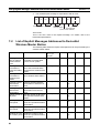
List of Explicit Messages Addressed to DeviceNet Wireless Master Station. . . . . . . . . . . . . . .
88
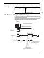
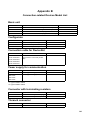
7-3
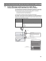
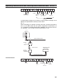
Explicit Messages Addressed to DeviceNet Slave Connected before
DeviceNet Wireless Slave Station. . . . . . . . . . . . . . . . . . . . . . . . . . . . . . . . . . . . . . . . . . . . . . . . 101
SECTION 8
Using the Configurator . . . . . . . . . . . . . . . . . . . . . . . . . . . . . . .107
8-1
Additional Functions. . . . . . . . . . . . . . . . . . . . . . . . . . . . . . . . . . . . . . . . . . . . . . . . . . . . . . . . . . 108
8-2
Wireless Network Configuration Display . . . . . . . . . . . . . . . . . . . . . . . . . . . . . . . . . . . . . . . . . . 108
8-3
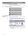
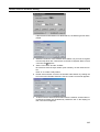
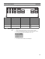
Wireless Network Parameter Editing . . . . . . . . . . . . . . . . . . . . . . . . . . . . . . . . . . . . . . . . . . . . . 112
8-4
Wireless Channel Monitor . . . . . . . . . . . . . . . . . . . . . . . . . . . . . . . . . . . . . . . . . . . . . . . . . . . . . 116
8-5
Running Test . . . . . . . . . . . . . . . . . . . . . . . . . . . . . . . . . . . . . . . . . . . . . . . . . . . . . . . . . . . . . . . . 121
SECTION 9
Communications Timing . . . . . . . . . . . . . . . . . . . . . . . . . . . . . .125
9-1
Remote I/O Communications Performances. . . . . . . . . . . . . . . . . . . . . . . . . . . . . . . . . . . . . . . . 126
9-2
Message Communication Performance . . . . . . . . . . . . . . . . . . . . . . . . . . . . . . . . . . . . . . . . . . . 134
SECTION 10
Troubleshooting . . . . . . . . . . . . . . . . . . . . . . . . . . . . . . . . . . . . .141
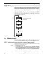
10-1 Normal Indication . . . . . . . . . . . . . . . . . . . . . . . . . . . . . . . . . . . . . . . . . . . . . . . . . . . . . . . . . . . . 142
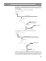
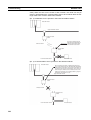
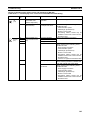
10-2 Troubleshooting . . . . . . . . . . . . . . . . . . . . . . . . . . . . . . . . . . . . . . . . . . . . . . . . . . . . . . . . . . . . . 144
10-3 Maintenance . . . . . . . . . . . . . . . . . . . . . . . . . . . . . . . . . . . . . . . . . . . . . . . . . . . . . . . . . . . . . . . . 152
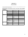
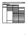
Appendices
A
Device Profiles . . . . . . . . . . . . . . . . . . . . . . . . . . . . . . . . . . . . . . . . . . . . . . . . . . . . . . . . . . .
155
B
Connection-related Devices Model List . . . . . . . . . . . . . . . . . . . . . . . . . . . . . . . . . . . . . . . .
161
C
Current Consumption List . . . . . . . . . . . . . . . . . . . . . . . . . . . . . . . . . . . . . . . . . . . . . . . . . .
163
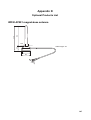
D
Optional Products List . . . . . . . . . . . . . . . . . . . . . . . . . . . . . . . . . . . . . . . . . . . . . . . . . . . . .
165
Index . . . . . . . . . . . . . . . . . . . . . . . . . . . . . . . . . . . . . . . . . . . . . .167
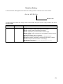
Revision History . . . . . . . . . . . . . . . . . . . . . . . . . . . . . . . . . . . . .171
x
SECTION 1
DeviceNet Wireless Unit
This section explains the features of the DeviceNet Wireless Unit, including system structure, types of units, basic functions, and
configurator outline.
1-1
1-2
1-3
DeviceNet Wireless Unit. . . . . . . . . . . . . . . . . . . . . . . . . . . . . . . . . . . . . . . . .
2
1-1-1
System configuration . . . . . . . . . . . . . . . . . . . . . . . . . . . . . . . . . . . .
2
1-1-2
Features. . . . . . . . . . . . . . . . . . . . . . . . . . . . . . . . . . . . . . . . . . . . . . .
2
1-1-3
Types of units . . . . . . . . . . . . . . . . . . . . . . . . . . . . . . . . . . . . . . . . . .
3
1-1-4
Model list . . . . . . . . . . . . . . . . . . . . . . . . . . . . . . . . . . . . . . . . . . . . .
4
Basic Functions of the DeviceNet Wireless Unit . . . . . . . . . . . . . . . . . . . . . .
4
1-2-1
Replacing data . . . . . . . . . . . . . . . . . . . . . . . . . . . . . . . . . . . . . . . . .
4
1-2-2
I/O allocation . . . . . . . . . . . . . . . . . . . . . . . . . . . . . . . . . . . . . . . . . .
6
1-2-3
DeviceNet wireless unit status . . . . . . . . . . . . . . . . . . . . . . . . . . . . .
8
1-2-4
Slave error flag . . . . . . . . . . . . . . . . . . . . . . . . . . . . . . . . . . . . . . . . .
8
1-2-5
Disconnect/Connect Switch . . . . . . . . . . . . . . . . . . . . . . . . . . . . . . .
9
1-2-6
DeviceNet node addresses . . . . . . . . . . . . . . . . . . . . . . . . . . . . . . . .
10
1-2-7
DeviceNet wireless unit default setting values . . . . . . . . . . . . . . . . .
11
1-2-8
Serial Number Check . . . . . . . . . . . . . . . . . . . . . . . . . . . . . . . . . . . .
11
Configurator Outline . . . . . . . . . . . . . . . . . . . . . . . . . . . . . . . . . . . . . . . . . . . .
12
1-3-1
Configuration . . . . . . . . . . . . . . . . . . . . . . . . . . . . . . . . . . . . . . . . . .
12
1-3-2
Operating environment . . . . . . . . . . . . . . . . . . . . . . . . . . . . . . . . . . .
12
1-3-3
Outline of functions . . . . . . . . . . . . . . . . . . . . . . . . . . . . . . . . . . . . .
13
1-4
Application Limitations . . . . . . . . . . . . . . . . . . . . . . . . . . . . . . . . . . . . . . . . .
14
1-5
Points for Consideration with Wireless Systems . . . . . . . . . . . . . . . . . . . . . .
16
1-5-1
16
Construction of multiple wireless systems . . . . . . . . . . . . . . . . . . . .
1
Section 1-1
DeviceNet Wireless Unit
1-1
DeviceNet Wireless Unit
The DeviceNet wireless unit, consisting of a DeviceNet wireless master station and a DeviceNet wireless slave station, allows wireless communication
with the DeviceNet slave.
Basically, the wireless master station is connected to the DeviceNet network
and acts as either a virtual DeviceNet slave or wireless network master station
for the DeviceNet master unit. The wireless slave station acts as either a wireless network slave station or a virtual DeviceNet master with the DeviceNet
slave unit.
This unit conforms to the following radio wave standards.
WD30-ME/-SE
WD30-ME01/-SE01
Japan: ARIB STD-T66
USA: FCC part 15.247
Canada: IC RSS 210
Europe: ETS 300 440
Japan: ARIB STD-T66
USA: FCC part 15.247
Conformance with these standards means that the antenna can be installed
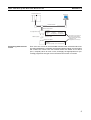
separately. The unit can be purchased as a set with a pencil antenna (WD30ME/-SE) or with a magnet-base antenna (WD30-ME01/-SE01). (The diagrams in this manual are for the WD30-ME/-SE.)
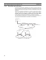
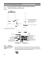
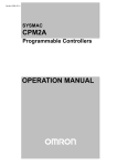
1-1-1
System configuration
DeviceNet master unit
Configurator
DeviceNet network
Wireless master
station
DeviceNet cable
DC24V power
supply
Wireless network
Wireless slave station
Wireless slave station
DeviceNet slaves
1-1-2
Features
DeviceNet slaves can be
made wireless
2
Wireless DeviceNet slaves allows for a variety of field level applications.
Section 1-1
DeviceNet Wireless Unit
We recommend that this function be used for applications that are not
required to operate in real time (such as displays for indicators and manufacturing instruction data transmissions).
Errors can be monitored
DeviceNet slave error information (including errors in wireless slave stations)
can be assigned to two or four status words and monitored from the PLC.
Abundant number of
wireless channels allows
the construction of
multiple systems in the
same area
Since the wireless region is divided into 34 frequencies from 2,400 to
2,483.5MHz, you can select an unused frequency for building multiple systems.
Relay functions make
possible an extension in
communications
distances
Although communications distances vary according to the installation environment, the goal indoors is 60m in line of sight.
Using a spectral spread method (DS: direct spread) as a modulation method
achieves high-quality communications even in areas of excess noise.
The relay functions allow an increase in the communications area (to a maximum of 3 stages).
DeviceNet slaves may also be connected to the relay station.
However, relay station system settings can only be performed from the configurator.
Diversity functions
Multi-pass phasing is improved with a diversity system (which requires 2
antennas).
The effects of this function are observed when used in areas where variations
in radio waves (such as reflections) occur.
Maximum number of I/O
per wireless master
station increased
Depending on the switch settings of the wireless master station, the maximum
number of I/O per wireless master station can be increased to 100 words/
100 words (IN/OUT). The maximum number of wireless slave stations that
can be connected has increased to 64.
Magnet-base antenna
added to lineup
Using the magnet-base antenna, the station itself can be installed inside a
control panel with the antenna installed outside. Also, because it is mounted
with a magnet, the position of the antenna can be adjusted easily when, for
example, the control panel is moved. Attenuation in the antenna cable (2m),
however, limits the maximum communications distance to approximately 50m
indoors.
1-1-3
Types of units
DeviceNet wireless master
station (Wireless master
station)
• Connects to the DeviceNet network and acts as a virtual DeviceNet slave.
• Maximum number of I/O as DeviceNet slave: IN/OUT = 32 words (512
points)/32 words (512 points) or 100 words (1,600 points)/100 words
(1,600 points) depending on the DIP switch setting. However, if Status is
selected, IN/OUT = 30 words (480 points)/32 words (512 points) or
96 words (1,536 points)/100 words (1,600 points) depending on the DIP
switch setting.
• As the wireless network master station, it controls a maximum of 64 wireless slave stations and sends remote I/O transmissions.
• The wireless master station was tested at the test laboratories of a third
part organization authorized by the ODVA. It is authorized as being in
conforming to ODVA conformance software.
Multi-pass
phasing
Multi-pass phasing is the phenomenon of a radio wave being transmitted form a single point,
passing through multiple propagation paths, and then arriving at a single point.
3
Section 1-2
Basic Functions of the DeviceNet Wireless Unit
DeviceNet wireless slave
station (Wireless slave
station)
• As an slave station for the wireless network, it exchanges remote I/O communications with the wireless master station via the wireless line.
• Acts as a virtual DeviceNet master with DeviceNet slaves.
• Connects with a maximum of 63 DeviceNet slaves and performs a maximum of 64 words (1,024 points) I/O control. (Even if multiple wireless
slave stations are used, the maximum number of nodes for DeviceNet
slaves is 63.)
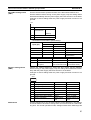
1-1-4
Model list
Type
No. of inputs/
outputs
DeviceNet
None
wireless
master station
None
DeviceNet
wireless slave
station
No. of words in PLC I/O
memory
IN
Status: 2 or
4 words (See
note.)
OUT
0 words
0 words
0 words
I/O
Unit voltage Installation
connection
None
Supplied by Screws
power for
external
communications
None
Model
Model
WD30-ME
Model
WD30ME01
Model
WD30-SE
Model
WD30SE01
Note When set to “status”
Accessories
The following accessories are included with purchase of both wireless master
station and slave station:
• 2 antennas (ME/-SE: pencil antenna; ME01/-SE01: magnet-base
antenna)
• User’s manual
• Sticker (Attach in a visible location.)
• 2 installation screws (with nuts)
• Declaration of Conformity (CE) (Provided with ME/-SE models only.)
Applicable connectors
1-2
1-2-1
Basic Functions of the DeviceNet Wireless Unit
Replacing data
Initializing the wireless
master station
4
Use DeviceNet micro-connectors for communications connectors. A list of
recommended connectors in the appendix.
When the power supply is turned on, the wireless master station adds each
registered wireless slave station. When wireless communication begins with
an slave station, if the number of I/O points on the DeviceNet slave connected
to the slave station and the I/O points registered for the wireless master station are identical, it is added. If they are not identical, an I/O configuration
error will occur.
Section 1-2
Basic Functions of the DeviceNet Wireless Unit
DeviceNet master unit
Configurator
DeviceNet network
Wireless master station
I/O configuration check
Addition process
I/O points
WNODE
IN points
OUT points
1 word (16 points) 1 word (16 points)
01
------Wireless network
Wireless slave station
If the number of I/O points on
the wireless master station
and the wireless slave station
is different, an I/O
configuration error will occur.
WNODE=01
I/O points
IN: 1 word (16 points), OUT: 1 word (16 points)
Processing when an error
occurs
Even if an error occurs in the DeviceNet network below a wireless slave station after initialization is complete, the wireless network polling communication
will continue as normal. The user should monitor the status at his device
(PLC, computer) when an error occurs, and apply the appropriate error processing program for the type of error and the area in which it occurred.
5
Section 1-2
Basic Functions of the DeviceNet Wireless Unit
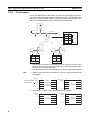
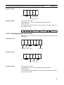
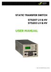
1-2-2
I/O allocation
I/O for DeviceNet slaves is allocated in the wireless slave stations by ascending order of DeviceNet node address without leaving any unused areas, and
then in the wireless master station by ascending order of slave station wireless node address (WNODE) without leaving any unused areas.
DeviceNet master unit
Network power supply
DeviceNet network
Terminal resistor
IN
OUT
#3 IN
#3 OUT
#4 IN
#4 OUT
# 1 IN
#1 OUT
#2 IN
#2 OUT
WNODE=01
Wireless
master
station
WNODE=02
Wireless network
Allocated in ascending order of WNODE
DeviceNet slaves
DeviceNet slaves
#2
#4
DeviceNet slaves
Wireless slave
station
#1
DeviceNet slaves
Wireless slave
station
WNODE=02
#3
WNODE=01
IN
OUT
IN
OUT
#1 IN
#1 OUT
#3 IN
#3 OUT
#2 IN
#2 OUT
#4 IN
#4 OUT
Allocated in ascending
order of DeviceNet node
address
Allocated in ascending
order of DeviceNet node
address
• The IN and OUT areas are allocated in units of 16 points (1 word). In the
case of 8-point units, the lower byte (bits 0 to 7) is allocated and the upper
byte (bits 8 to 15) is set to 00 Hex.
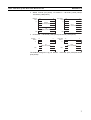
• The following four types of I/O allocations can be set using the DIP switch.
1,2,3...
1. Status 2 words (32 points), I/O IN/OUT = 30 words (480 points)/32 words
(512 points)
IN area
Wd+0
For wireless master
+1
station NNODE
15
0
Status
(2 words, fixed)
OUT area
Wd+0
15
+1
0
OUT
(Max. 32 words)
IN
(Max. 30 words)
+31
+31
2. I/O IN/OUT = 32 words (512 points)/32 words (512 points)
IN area
Wd+0
+1
+31
6
15
0
IN
(Max. 32 words)
OUT area
Wd+0
+1
+31
15
0
OUT
(Max. 32 words)
Section 1-2
Basic Functions of the DeviceNet Wireless Unit
3. Status 4 words (64 points), I/O IN/OUT = 96 words (1,536 points)/
100 words (1,600 points)
IN area
Wd+0
15
+1
0
OUT area
Wd+0
15
0
+1
Status (4 words, fixed)
OUT
(Max. 100 words)
IN
(Max. 96 words)
+99
+99
4. I/O IN/OUT = 100 words (1,600 points)/100 words (1,600 points)
IN area
Wd+0
15
0
+1
OUT area
Wd+0
0
+1
IN
(Max. 100 words)
+99
15
OUT
(Max. 100 words)
+99
The default settings are "(2) I/O IN/OUT = 32 words (512 points)/32 words
(512 points)".
7
Section 1-2
Basic Functions of the DeviceNet Wireless Unit
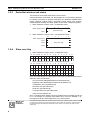
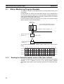
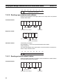
1-2-3
DeviceNet wireless unit status
The format for the IN area status area is shown below.
Confirm this status at the CPU unit, and prepare an error processing program
for sending commands to (Explicit messages) and obtaining detailed status
reports (wireless network status, DeviceNet master status) from wireless
master stations showing error flags. (Refer to SECTION 3 Sample Program.)
1. When maximum number of I/O = 32 words/32 words:
8
15
Status begins Wd+0
7
1
0
Slave error flag
Wd+1
2. When maximum number of I/O = 100 words/100 words:
15
8
7
1
0
Status begins Wd+0
Wd+1
Wd+2
Slave error flag
Wd+3
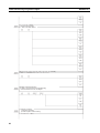
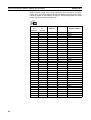
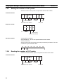
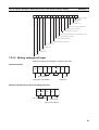
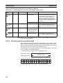
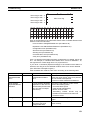
1-2-4
Slave error flag
1. When maximum number of I/O = 32 words/32 words:
15 14 13 12 11 10 9 8 7 6 5 4 3 2 1
16 15 14 13 12 11 10 9 8 7 6 5 4 3 2
0
1
32 31 30 29 28 27 26 25 24 23 22 21 20 19 18 17
2. When maximum number of I/O = 100 words/100 words:
15 14 13 12 11 10 9 8 7 6 5 4 3 2 1
16 15 14 13 12 11 10 9 8 7 6 5 4 3 2
0
1
32 31 30 29 28 27 26 25 24 23 22 21 20 19 18 17
48 47 46 45 44 43 42 41 40 39 38 37 36 35 34 33
64 63 62 61 60 59 58 57 56 55 54 53 52 51 50 49
Each of the following for the DeviceNet master status of added wireless slave
stations is set to an OR value.
Incorrect switch setting/EEPROM error (bit address 00)
Repetitive node address/Busoff detection (bit address 01)
Configuration error (bit address 03)
Structural error (bit address 04)
Send error (bit address 05)
Communication error (bit address 06)
Verify error (bit address 07)
Also, if a wireless slave station has been registered but not added, the bit will
be 1. For example, if a wireless slave station error occurs for WNODE = 16,
the uppermost bit for "status begin word +0" (16) becomes 1.
Master unit
I/O point
limitations
8
Each wireless master station can control a maximum of 512 (or 1,600) I/O points. However, there
are limits to the number of I/O points per node for each master unit. Therefore, systems should
be designed without exceeding the limitations for the number of I/O points per node for each
master unit.
Basic Functions of the DeviceNet Wireless Unit
Section 1-2
Refer to the "DeviceNet User’s Manual" for details concerning DeviceNet
master status errors.
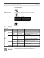
1-2-5
Disconnect/Connect Switch
The Disconnect/Connect Switch function that was introduced with CS/CJseries DeviceNet master units can be used for wireless slave stations. A bit is
allocated to each wireless slave station’s WNODE, and if this bit is turned ON
(1), wireless I/O communications and message communications with the corresponding wireless slave station will stop (i.e., the wireless slave station is
disconnected from the network). This function is mainly used to reserve space
for wireless slave stations to be added in the future (i.e., I/O points have been
registered in the wireless master station but no wireless slave station has
been connected yet).
Wireless slave stations that have been disconnected from the network do not
need to be considered when calculating the wireless communications cycle
time.
In the DeviceNet master unit’s I/O area, 0 is set in the IN area allocated to
wireless slave stations that have been set to leave the network.
9
Section 1-2
Basic Functions of the DeviceNet Wireless Unit
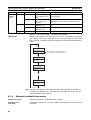
1-2-6
DeviceNet node addresses
DeviceNet node addresses (NNODEs) are included in wireless master stations. The master unit controls the assignment of DeviceNet slave I/O data
registered with wireless slave stations to areas corresponding to these node
addresses.
Wireless node addresses (WNODEs) are included in wireless slave stations.
These node addresses are used for control by wireless master stations.
Therefore, there is no purpose in assigning the wireless slave station
DeviceNet node addresses (NNODEs) to I/O. Normally, a 7 segment LED is
used to display the DeviceNet node address on wireless slave stations.
Since DeviceNet node addresses are controlled by wireless slave stations, be
sure to set the DeviceNet slaves so that there is no redundancy.
DeviceNet master unit
DeviceNet network
There should be no
redundancy within this area.
Wireless master
station
DeviceNet slaves
Wireless network
Wireless slave
station
DeviceNet slaves
Redundancy is acceptable in this area.
Wireless
slave
station
DeviceNet slaves
There should be no redundancy within this area.
10
Basic Functions of the DeviceNet Wireless Unit
1-2-7
Section 1-2
DeviceNet wireless unit default setting values
Wireless unit network default settings are on a 1:1:2 structure of wireless
master station: wireless slave station: DeviceNet slave with IN/OUT = 16
points/16 points, as shown in the figure below.
Wireless master station
I/O points: IN 1 word (16 points)
OUT 1 word (16 points)
Registered wireless slave station: 1 node
Wireless slave station
WNODE=01
IN/OUT=1 word (16 points) 1 word (16 points)
DeviceNet slave
NNODE=01
IN/OUT=
(16 points/0 point)
DeviceNet slave
NNODE=02
IN/OUT=
(0 point/16 points)
The default settings can be returned to on both wireless master stations and
slave stations using the DIP switches in SET mode. Refer to 2-4 System Initial
Setting and Starting Communications for detailed setting information.
1-2-8
Serial Number Check
With the release of the WD30-ME with Identity Object Revision value 3.02, it
has become possible to register the serial number (the wireless slave station’s
own unique ID) of wireless slave stations to non-volatile memory in the wireless master station.
If a wireless slave station is registered to a wireless master station using
switch operations at the wireless master station, or if serial number check is
enabled for the wireless slave station by editing the device parameters using
the configurator, and the serial number is written, the wireless slave station’s
serial number is registered to the wireless master station’s non-volatile memory.
This function is for preventing incorrect WNODE settings for wireless slave
stations, and communications errors resulting from the effects of intermodulation.
If serial number check is enabled for all the wireless slave stations registered
to a wireless master station, the dot on the right-hand side of the wireless
master station’s 7-segment LED lights.
11
Section 1-3
Configurator Outline
Also, if serial number check is enabled for all the wireless slave stations registered to a wireless master station, and all of the wireless slave stations’ serial
numbers are registered to the wireless master station, the dot on the left-hand
side of the wireless master station’s 7-segment LED lights.
1-3
Configurator Outline
This is the Windows application that runs the DeviceNet computer master station.
Master and slave unit settings can be referenced (slave entry, I/O allocations,
wireless network protocol parameters, commands issued), conditions monitored, used frequency bands (channels) monitored, and running tests performed from the DeviceNet configurator (Ver. 2.0 or later).
1-3-1
Configuration
The computer running the Configurator is connected to the DeviceNet network by installing an OMRON DeviceNet Board in the computer or by connecting the computer to a serial communications port (peripheral port) of the
CS1W-DRM21 DeviceNet Unit on a CS1-series PLC.
Note In both cases, the same online functions are supported.
1-3-2
Operating environment
This is the operating environment for the DeviceNet configurator.
Product
Configurator
(Ver. 2.@)
Model
Contents
Method of connecting
Personal
personal computer to
computer
network
WS02-CFDC1-E Installation disk Either one of the following IBM PC/AT or
(CD-ROM)
methods
compatible
• Serial connection
• Dedicated PCMCIA Card
• Dedicated ISA Board
(see table below)
OS
Windows 95, 98,
2000 or NT4.0
Note Use the following dedicated Boards and Card
Model
3G8F5-DRM21
3G8E2-DRM21
12
Contents
Personal
computer
Dedicated ISA Board and Configurator
IBM PC/AT or
(Ver. 2.@) installation disk
compatible
Dedicated PCMCIA Card and Configurator
(Ver. 2.@) installation disk
OS
Windows 95, 98 or NT4.0
Windows 95 or 98
Section 1-3
Configurator Outline
1-3-3
Outline of functions
• Monitor the network condition of the wireless unit
• Set and reference parameters of the wireless unit (setting/referencing
wireless slave entry, number of I/O points, and wireless slave station routing information)
• Monitor channels (monitor the transmission levels of used frequency
bands, and keep logs)
• Running test (perform running tests according to user configurations without grouping PC and PLC applications, and leave a test log with time
information)
• Wireless communication cycle time calculation
Refer to SECTION 8 Using the Configurator for a detailed explanation of
these functions.
13
Section 1-4
Application Limitations
1-4
Application Limitations
The wireless unit is not designed to be compatible with every type of application that uses DeviceNet. Do not use the unit with the following applications.
1,2,3...
1. Applications that require real-time control
Do not use the unit with applications that require real-time control. In particular, it cannot be used under conditions that require responsiveness
greater than that outlined in "Section 9 Communications Timing".
Applications that do not require real-time control, such as indicators, equipment error monitors, and parts picking operation, are recommended.
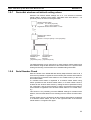
2. Applications that use FINS message communications
Wireless units do not support FINS message communications. For example, although CX-Programmer Ver. 2.1 and later versions support online
connection (i.e., remote programming and monitoring) to PLCs on DeviceNet networks (e.g., PLCs with CS/CJ-series DeviceNet Units or programmable slaves), this functionality is not available via wireless units.
CX-Programmer
installed on a
computer
CS1
Upper DeviceNet network
Wireless master
station
Programmable slave
Wireless slave
station
Lower DeviceNet network
14
Section 1-4
Application Limitations
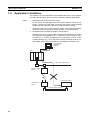
3. Applications that use Peer to Peer communications between the upper DeviceNet network DeviceNet master and the lower DeviceNet net-work DeviceNet master.
DeviceNet master unit
Upper DeviceNet network
Wireless master
station
DeviceNet master unit
Wireless network
Wireless slave
station
Lower DeviceNet network
15
Section 1-5
Points for Consideration with Wireless Systems
4. Applications that require setting the DeviceNet slave "Communication
Error Output" to "Standby"
When a wireless slave station is reset from some error, it is possible that
the DeviceNet slave output will be momentarily cleared. Therefore, applications that set the output to "Standby" during communication errors can
not be used.
DeviceNet master unit
Upper DeviceNet network
Wireless master
station
Wireless network
Wireless slave
station
Lower DeviceNet network
Output set to
"Standby" during
transmission errors
DeviceNet slaves
OUT
Cleared momentarily
5. Applications where software reset (Explicit messages) must be performed
for the slave station from the upper DeviceNet network
1-5
1-5-1
Points for Consideration with Wireless Systems
Construction of multiple wireless systems
When constructing a system for using multiple wireless master stations, the
following points must be considered. Consult your OMRON representative.
16
Section 1-5
Points for Consideration with Wireless Systems
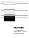
Setting wireless channels
It is necessary to select frequencies for the wireless channels that are not
interfered with by radio waves. (Radio interference can be handled by retry
processes between the wireless networks, but will lengthen the system
response time.)
With this unit, 34 wireless channels can be selected from. Taking the following
points into consideration, however, the maximum number of wireless systems
usable in a single area without radio interference is, as a rough guide, 10.
1. It is possible that, for example, there is a wireless LAN on site that uses the
same frequency as this unit. Select an unused wireless channel using the
Configurator’s wireless channel monitor function.
2. Do not select neighboring wireless channels as they have a large amount
of interference.
3. Due to the fundamental nature of radio waves, if 2 or more waves with different frequencies are output at exactly the same time, mutual interference
will occur between the different frequencies, and new waves will be generated with frequencies at intervals equal to the intervals between the output
frequencies. (This phenomenon is called “intermodulation.”)
Wireless master
station
f1-(f2 - f1)=1ch
Wireless slave
station
Radio wave created
by intermodulation
f1=5ch
Wireless master
station
Wireless slave
station
f2=9ch
f2+(f2 - f1)=13ch
Radio wave created
by intermodulation
Do not select the frequencies of waves created by intermodulation.
Antenna separation
distance
The distance between wireless units has a large influence on the amount of
interference received. In particular, there may often be cases where wireless
master stations are installed relatively closely to each other. Separate the
antennas for different wireless master stations by at least 1 m (at least 2 m, if
possible).
Test confirmation
Perform a test to see whether or not the wireless units are receiving interference. Using the Configurator’s running test function, obtain the packet error
rate, and, based on this, determine whether or not the communications quality
is sufficient for the application. (As a rough guide, the packet rate should be
less than 0.01.)
Intermodulation
Due to the fundamental nature of radio waves, if 2 or more waves with different frequencies are
output at exactly the same time, mutual interference will occur between the different frequencies,
and new waves will be generated with frequencies at intervals equal to the intervals between the
output frequencies.
17
Points for Consideration with Wireless Systems
Section 1-5
!Caution Communications errors caused by intermodulation
Communications errors and retry processing may occur due to intermodulation and consequently cause transmission delays. In order to eliminate the
influence of intermodulation, do not set the wireless channels for wireless
units in every system to frequencies at regular intervals.
Before starting operation of the wireless system using a WD30-ME with Identity Object Revision value 3.02, either register wireless slave stations to the
wireless master station using switch operations at the wireless master station,
or enable serial number check for the wireless slave stations using the configurator, and then register the serial numbers of the wireless slave stations to
the wireless master station by writing the serial numbers.
18
SECTION 2
Hardware Settings and Checking of Operations
This section gives specific explanations of the operations and procedures necessary for you to use the DeviceNet wireless unit. Follow
the explanations in this section to perform operation check procedures.
2-1
2-2
2-3
2-4
2-5
2-6
2-7
Basic Operation Procedure . . . . . . . . . . . . . . . . . . . . . . . . . . . . . . . . . . . . . . .
20
2-1-1
Basic operation procedures flowchart. . . . . . . . . . . . . . . . . . . . . . . .
20
Pre-work Preparations. . . . . . . . . . . . . . . . . . . . . . . . . . . . . . . . . . . . . . . . . . .
22
2-2-1
Determination of system configuration . . . . . . . . . . . . . . . . . . . . . .
22
2-2-2
Confirmation of specifications . . . . . . . . . . . . . . . . . . . . . . . . . . . . .
22
2-2-3
Temporary installation and installation test . . . . . . . . . . . . . . . . . . .
23
Hardware Settings and Wiring . . . . . . . . . . . . . . . . . . . . . . . . . . . . . . . . . . . .
24
2-3-1
DeviceNet wireless master station settings and installation . . . . . . .
24
2-3-2
DeviceNet wireless slave station settings and installation . . . . . . . .
24
2-3-3
Installation of connection equipment . . . . . . . . . . . . . . . . . . . . . . . .
25
2-3-4
Cable connections. . . . . . . . . . . . . . . . . . . . . . . . . . . . . . . . . . . . . . .
25
System Initial Setting and Starting Communications . . . . . . . . . . . . . . . . . . .
26
2-4-1
System start. . . . . . . . . . . . . . . . . . . . . . . . . . . . . . . . . . . . . . . . . . . .
26
2-4-2
DeviceNet slave entry . . . . . . . . . . . . . . . . . . . . . . . . . . . . . . . . . . . .
27
2-4-3
DeviceNet wireless slave station entry . . . . . . . . . . . . . . . . . . . . . . .
29
2-4-4
Scan list valid settings. . . . . . . . . . . . . . . . . . . . . . . . . . . . . . . . . . . .
31
Operation Confirmation . . . . . . . . . . . . . . . . . . . . . . . . . . . . . . . . . . . . . . . . .
31
2-5-1
Unit LED confirmation. . . . . . . . . . . . . . . . . . . . . . . . . . . . . . . . . . .
31
2-5-2
Status confirmation . . . . . . . . . . . . . . . . . . . . . . . . . . . . . . . . . . . . . .
31
2-5-3
Confirmation by reading/writing data . . . . . . . . . . . . . . . . . . . . . . .
32
Other Operations . . . . . . . . . . . . . . . . . . . . . . . . . . . . . . . . . . . . . . . . . . . . . . .
32
2-6-1
DeviceNet wireless slave station deletion. . . . . . . . . . . . . . . . . . . . .
32
2-6-2
DeviceNet wireless master station initialization. . . . . . . . . . . . . . . .
35
2-6-3
DeviceNet wireless slave stations initialization . . . . . . . . . . . . . . . .
36
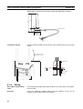
Deciding the Antenna Installation Position . . . . . . . . . . . . . . . . . . . . . . . . . .
38
2-7-1
41
Example of installation inside a control panel . . . . . . . . . . . . . . . . .
19
Section 2-1
Basic Operation Procedure
2-1
Basic Operation Procedure
Specific examples illustrating the basic operation procedure of the DeviceNet
wireless unit are given in this section.
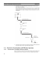
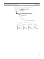
2-1-1
Basic operation procedures flowchart
The basic operation procedure is shown below. Refer to the "DeviceNet
User’s Manual" and the "DeviceNet Slave Manual" for details concerning settings and connections.
Pre-work confirmation
Determination of system configuration
Confirmation of specifications
Temporary installation and installation test
(See page 22).
(See page 22).
(See page 23).
Hardware settings and
wiring
DeviceNet Wireless master station settings and installation
DeviceNet Wireless slave station settings and installation
Installation of connection equipment
Cable connections
System initialization and
starting communication
System start
DeviceNet slave entry
DeviceNet wireless slave station entry
Scan list valid settings
20
(See page 24).
(See page 24).
(See page 25).
(See page 25).
(See page 26).
(See page 27).
(See page 29).
(See page 31).
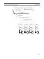
Section 2-1
Basic Operation Procedure
Operation confirmation
Unit LED confirmation
(See page 31).
Confirmation by reading/writing data
(See page 32).
21
Section 2-2
Pre-work Preparations
2-2
Pre-work Preparations
Items to be checked before performing installation work are explained
here.
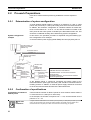
2-2-1
Determination of system configuration
A single wireless master station is limited to a maximum of 1,024 or 3,200
points, 512 (32 words) or 1,600 (100 words) points each for both IN and OUT.
In addition, the maximum configuration in a wireless network of master stations to slave stations is 1 to 32 or 1 to 64, and the maximum number of IN/
OUT points for the entire system is limited by the DeviceNet master unit. This
should be considered carefully when determining system configuration.
System configuration
example
In this section, the operation procedure is explained using the following system configuration as an example.
A communications power supply (Model S82K) has been purposely left out
DeviceNet master unit
Model CS1W-DRM21
(NNODE=10)
DeviceNet network
Wireless mater station
(NNODE=00)
Wireless network
Wireless slave
station
(WNODE=01)
(NNODE=00)
Wireless slave
station
(WNODE=02)
(NNODE=00)
DeviceNet slaves
Model DRT1-ID08C
(NNODE=01)
DeviceNet slaves
Model DRT1-MD16C
(NNODE=03)
DeviceNet slaves
DRT1-ID08C
Model DRT1-ID08C
NNODE=2
(NNODE=02)
NNODE: DeviceNet node address
WNODE: Wireless node address
ModelDRT-ID08C: 8 environment-resistant
terminal inputs
DeviceNet slaves
ModelDRT1-MD16C: 16 environment-resistant
Model DRT1-MD16C
terminal inputs/outputs
(NNODE=04)
of the diagram above. It should be connected and supply power to the
DeviceNet network (both upper and lower) and should be connected with terminating resistor. In addition, an external power supply should be connected
to the environment-resistant terminal of the DeviceNet slave.
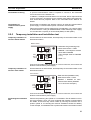
2-2-2
Confirmation of specifications
Confirmation of number of
IN/OUT points
Confirm that the number of IN/OUT points for each wireless master station is
no more than 512 or 1,600 (32 or 100 words).
In the example, the number of IN points is 8 × 4 = 32, and the number of OUT
points is 8 × 2 = 16.
Master unit
I/O
limitations
22
A single wireless master station can control up to 512 points (or 1,600 points) for both input and
output, but the number of I/O points per node is limited by the master unit. Be careful not to
exceed the limit for I/O points per master unit node when constructing your system.
Section 2-2
Pre-work Preparations
Confirmation of wiring
A special communications cable is required to connect to the DeviceNet
micro-connector on the wireless unit.
In addition, if multiple DeviceNet slaves are connected, branch taps should be
used as necessary. Terminators for the wireless slave station DeviceNet network should also be prepared. Refer to the "DeviceNet User’s Manual" for
details.
Confirmation of
communications power
supply
2-2-3
Since power is supplied to the wireless unit from an external communications
power supply, a communications power connection must be made.
Taking the maximum current at startup into consideration, use a power supply
of at least 350mA. If using an OMRON S82K or S82J switching power supply,
use a model with a capacity of at least 30W (S82K) or 25W (S82J).
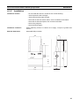
Temporary installation and installation test
Temporary installation of
wireless master station
Set the switches as shown below, and temporarily fix the master station in the
determined location.
Master station
W NODE
23
78
901
23
78
901
456
456
X10
X1
W CH
SW2
901
78
23
78
901
23
RUN
TEST
SET
456
456
X10
X1
SW3
• SW3=bit4 ON (positioning test)
• Mode select switch = TEST
• WNODE = test subject’s wireless
slave station WNODE
(This example starts at WNODE
= 01.)
• WCH = 01
ON
1 2 3 4 5 6 7 8
Connect a DeviceNet cable prepared for a micro-connector, and connect the
DC24V communications power supply.
Temporary installation of
wireless slave station
Set the switches as shown below, and temporarily fix the master station in the
determined location.
Slave station
W NODE
78
901
456
456
X10
SW2
X1
W CH
78
23
78
901
• SW3=bit4 ON (installation test)
• Mode select switch = TEST
• WNODE = WNODE for each
wireless slave station (WNODE
= 01 to 02 for this example.)
456
901
23
456
RUN
TEST
SET
23
23
78
901
X10
X1
SW3
ON
1 2 3 4 5 6 7 8
Connect a DeviceNet cable prepared for a micro-connector, and connect the
DC24V communications power supply.
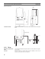
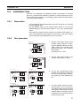
Performing the installation
test
Perform the positioning test. (Refer to 5-2 Installation Test for details concerning the procedure.) Once you have confirmed that wireless communications
are stable, ensure that they remain stable by securing the wireless unit in
position. (Refer to 2-7 Deciding the Antenna Installation Position for details.)
In this example, an installation test is performed between the wireless master
23
Section 2-3
Hardware Settings and Wiring
station and slave station 1, and the wireless master station and slave station
2.
2-3
Hardware Settings and Wiring
Settings and wiring to be performed before turning on the power supply to the
system are explained in this section.
2-3-1
DeviceNet wireless master station settings and installation
Settings
An example setting for a wireless master station is shown below. Refer to 4-1
DeviceNet Wireless Master Station Specifications for details concerning setting procedures. In this example, Status is selected and IN/OUT = 512/512
points (32 words/32 words).
DeviceNet master unit
Model CS1W-DRM21
(NNODE=00)
DeviceNet Network
Wireless master
station
Model WD30-M SW3=bit6
ON
SW1=bit3 ON
WNODE=01
NNODE=10
Mode select switch = SET
Installation
2-3-2
Use screws to firmly fix the wireless master station that has already been temporarily installed. Refer to 4-1 DeviceNet Wireless Master Station Specifications for details.
DeviceNet wireless slave station settings and installation
Settings
Settings example for each wireless slave station are shown below. Refer to 42 DeviceNet Wireless Slave Station Specifications for details concerning the
setting procedure.
In this example, the default settings should be used for all DeviceNet settings
apart from the node address. Refer to the "DeviceNet Slave Manual" for
details concerning the settings for each DeviceNet slave.
Terminating
resistor
installation
24
Terminating resistors are required not only for the wireless master station, but also on both ends
of the wireless slave stations’ DeviceNet network.
Section 2-3
Hardware Settings and Wiring
Wireless master station
SW3=bit6 ON
SW1=all OFF
WNODE=01
NNODE=00
Mode select switch=SET
Installation
2-3-3
Wireless
slave
station
Wireless network
Wireless
slave
station
SW3=bit6 ON
SW1=all OFF
WNODE=02
NNODE=00
Mode select switch=SET
DeviceNet slaves
Model DRT1-ID08C
(NNODE=01)
DeviceNet slaves
Model DRT1-ID08C
(NNODE=02)
DeviceNet slaves
Model DRT1-MD16C
(NNODE=03)
DeviceNet slaves
Model DRT1-MD16C
(NNODE=04)
Use screws to firmly fix the wireless slave stations that have already been
temporarily installed. Refer to 4-2 DeviceNet Wireless Slave Station Specifications for details.
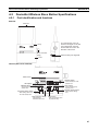
Installation of connection equipment
Connection equipment that requires installation is listed below.
• Shielded T-type branch connector
• Shielded terminating resistor
• Communications power supply (DC24V)
2-3-4
Cable connections
Connect a DeviceNet cable prepared for micro-connectors to the wireless
master and slave stations.
Connect the cables to the DeviceNet master (C200HW-DRM21-V1) and the
DeviceNet slave (environment-resistant terminal) to create the complete physical system network.
Example 1:
Connecting the cable on the side and installing a terminating resistor
Model DRS2-1
Shielded terminating resistor
Plug
Socket
Dedicated cable
Plug
Model
DCN2-1
Socket
Plug
Socket
25
Section 2-4
System Initial Setting and Starting Communications
Example 2:
Connecting the cable to the top, and installing a terminating resistor
Special cable
Plug
Socket
Plug
Model
DCN2-1
Socket
Plug
Model DRS2-2
Socket
Example 3:
Connecting the cable to the bottom, and installing a terminating resistor
Model DRS2-1
Shielded terminating resistor
Plug
Socket
Model DCN2-1
Plug
Plug
Socket
Socket
Dedicated cable
2-4
System Initial Setting and Starting Communications
The required entries, and deletion and initialization procedures following system start are explained in this section.
2-4-1
System start
Turn on the communications power source and the node power supply in the
following order.
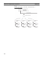
1,2,3...
1. DeviceNet slave (environment-resistant terminal) external power supply
2. DeviceNet master (C200HW-DRM21-V1) power supply
It is also OK to turn all power supplies on simultaneously.
26
Section 2-4
System Initial Setting and Starting Communications
DeviceNet slave entry
Register the number of DeviceNet slave I/O points in the wireless slave station.
If the same system configuration as for the network default settings (Refer to
1-2 Basic Functions of the DeviceNet Wireless Unit.) is used, there is no need
to do this registration.
The specifics of this example are explained below.
First, begin with the WNODE = 1 wireless slave station.
1. Confirm that the slave station node
address (NNODE) is not doubled
with the DeviceNet slave. In this example, NNODE-00 is OK.
Slave station
MS
NS
WS
N NODE
SW2
78
901
23
23
78
901
456
456
X10
X1
SW1
RUN
TEST
SET
ON
1 2 3 4
Slave station
MS
NS
WS
N NODE
SW2
78
901
23
23
78
901
456
456
X10
X1
SW1
RUN
TEST
SET
2. Check if the communications rate for
the slave station and the DeviceNet
slave is the same. In this example,
since default settings (125kbps) are
used, all of the bits for SW1 should
be OFF.
ON
1 2 3 4
Slave station
W NODE
78
901
456
X10
X1
W CH
901
23
23
78
901
78
SW2
RUN
TEST
SET
3. Since the DeviceNet slave is registered, set SW3 to "bit 6 = ON".
23
23
78
901
456
456
456
X10
X1
SW3
ON
1 2 3 4 5 6 7 8
Slave station
4. Set the mode select switch to "SET".
W NODE
78
901
456
X10
X1
W CH
23
23
78
901
78
901
456
SW2
456
RUN
TEST
SET
23
23
78
901
456
2-4-2
X10
X1
SW3
ON
1 2 3 4 5 6 7 8
27
System Initial Setting and Starting Communications
Section 2-4
Slave station
MS
NS WS
N NODE
SW2
23
78
901
23
78
901
456
456
X10
X1
SW1
RUN
TEST
SET
ON
5. Turn ON the wireless slave station
communications power supply.
After confirming that the LED display shows a decimal point display
(scan list invalid mode) and the NS
LED lights green, push SW2.
1 2 3 4
Slave station
MS
NS WS
SW2
N NODE
23
78
901
23
78
901
456
456
X10
X1
SW1
6. Once the decimal point display has
disappeared from the LED display,
DeviceNet slave entry is complete.
(scan list valid mode)
RUN
TEST
SET
ON
1 2 3 4
Slave station
7. Set SW3 to "bit 6 = OFF".
W NODE
23
78
901
23
78
901
456
456
X10
SW2
X1
W CH
901
78
78
23
23
RUN
TEST
SET
901
456
456
X10
X1
SW3
ON
1 2 3 4 5 6 7 8
Slave station
W NODE
78
901
456
456
X10
SW2
X1
W CH
78
23
23
78
901
456
901
RUN
TEST
SET
8. Set the mode select switch to
"RUN".
23
23
78
901
456
X10
X1
SW3
ON
1 2 3 4 5 6 7 8
9. If the NS LED lights green and the
LED display shows the node address, the system is in RUN operation status.
Slave station
MS
NS WS
SW2
N NODE
78
23
23
78
901
456
901
456
X10
X1
SW1
RUN
TEST
SET
ON
1 2 3 4
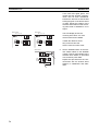
The operation for the WNODE = 2 wireless slave station is the same as steps
(1) through (9) above.
28
Section 2-4
System Initial Setting and Starting Communications
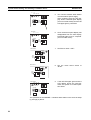
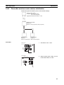
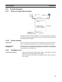
DeviceNet wireless slave station entry
Enter the wireless slave station in the wireless master station.
If the same system configuration as for the network default settings (Refer to
1-2 Basic Functions of the DeviceNet Wireless Unit.) is used, there is no need
to do this registration. In addition, when not using the WNODE = 1 wireless
slave station (entry is complete with default settings when sent from the factory), it must be deleted before proceeding with entry.
The specifics of this example are explained below.
First, begin with the WNODE = 1 wireless slave station.
Master station
W NODE
78
901
23
23
78
901
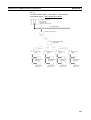
1. Use the wireless master station WNODE = 1.
456
456
X10
X1
W CH
SW2
901
78
78
23
23
RUN
TEST
SET
901
456
456
X10
X1
SW3
ON
1 2 3 4 5 6 7 8
Master station
W NODE
78
901
456
X10
X1
W CH
901
23
23
78
901
78
SW2
RUN
TEST
SET
23
23
78
901
2. To enter the wireless slave station,
set SW3 to "bit 6 = ON".
456
456
456
X10
X1
SW3
ON
1 2 3 4 5 6 7 8
Master station
W NODE
78
901
456
X10
X1
W CH
23
23
78
901
78
901
456
SW2
RUN
TEST
SET
3. Set the wireless master station
mode select switch to "SET".
23
23
78
901
456
456
X10
X1
SW3
ON
1 2 3 4 5 6 7 8
Master station
MS
NS
WS
N NODE
23
23
78
901
78
901
456
456
2-4-3
X10
X1
SW1
SW2
4. Turn ON the wireless master station
communications power supply.
Once the MS LED flashes green
and SW2 is pressed, the addition of
the wireless slave station begins.
RUN
TEST
SET
ON
1 2 3 4
29
System Initial Setting and Starting Communications
Master station
MS
NS
WS
SW2
N NODE
23
78
901
23
78
901
456
456
X10
X1
SW1
RUN
TEST
SET
ON
Section 2-4
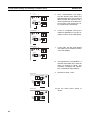
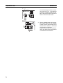
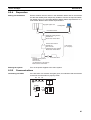
5. Once communication has begun
with the wireless slave station, the
WS LED lights green, the number of
IN/OUT points are acquired, and a
check is performed on the total number of points. If the check is OK, entry is performed automatically.
1 2 3 4
Master station
MS
NS
6. If entry is completed correctly, the
registered WNODE (01 for this example) is shown in the LED display.
WS
N NODE
SW2
78
901
23
23
78
901
456
456
X10
X1
SW1
RUN
TEST
SET
ON
1 2 3 4
Master station
MS
NS
7. If entry fails, the WS LED flashed
red, and the error condition is shown
in the LED display.
WS
N NODE
78
23
23
78
SW2
901
456
901
456
X10
X1
SW1
RUN
TEST
SET
ON
1 2 3 4
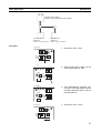
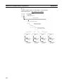
8. The registration for the WNODE = 2
wireless slave station is the same as
steps (1) through (7) above. This
procedure completes the registration of all wireless slave stations.
9. Set SW3 to "bit 6 = OFF".
Master station
W NODE
78
901
456
456
X10
X1
W CH
901
23
23
78
901
78
SW2
RUN
TEST
SET
23
23
78
901
456
456
X10
X1
SW3
ON
1 2 3 4 5 6 7 8
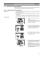
10. Set the mode select switch to
"RUN".
Master station
W NODE
78
901
456
456
X10
X1
W CH
78
901
23
23
78
901
456
SW2
456
RUN
TEST
SET
23
23
78
901
X10
X1
SW3
ON
1 2 3 4 5 6 7 8
30
Section 2-5
Operation Confirmation
Master station
MS
NS
WS
N NODE
SW2
23
78
901
23
78
901
456
456
X10
X1
SW1
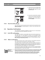
11. If the MS, NS, and WS LEDs all light
green and nothing is shown in the
LED display, the system is in RUN
operation status.
RUN
TEST
SET
ON
1 2 3 4
Slave station
MS
NS
WS
SW2
N NODE
78
23
23
78
901
456
901
456
X10
X1
SW1
RUN
TEST
SET
12. At this point, the MS, NS, and WS
LEDs on each wireless slave station
light green, too, and the node addresses (NNODE = 0) are shown in
the LED displays.
ON
1 2 3 4
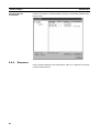
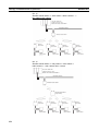
2-4-4
Scan list valid settings
Scan list creation and entry and the scan list valid mode are performed from
the DeviceNet master (C200HW-DRM21-V1). Refer to the "DeviceNet User’s
Manual" for details.
2-5
Operation Confirmation
The confirmation procedure for whether or not remote I/O communications
are performed correctly is explained in this section.
2-5-1
Unit LED confirmation
If the MS and NS LEDs on all DeviceNet slaves (environment-resistant terminals) light green, the node address is shown on the DeviceNet master
(C200HW-DRM21-V1) LED display (the decimal display disappears), and the
MS and NS LEDs light green, wireless remote I/O communications are operating correctly in scan list enable mode.
2-5-2
Status confirmation
If the STATUS setting is made, status information is automatically assigned to
the 2 words at the top of the IN area. (The position is fixed.)
The IN/OUT data for DeviceNet slaves (environment-resistant terminals) is
first assigned to the IN areas and OUT areas by the wireless slave stations in
ascending order of WNODE and is then assigned by the wireless master stations in ascending order of NNODE (1 to 4 in this example).
The IN and OUT areas are allocated in units of 16 points (1 word). Because
the slaves are 8-point units, the lower bytes (bits 0 to 7) are allocated and the
upper bytes (bits 8 to 15) are set to 00 Hex.
Replacing
wireless
slave stations
When a wireless slave station has been replaced, with reference to 2-4-2 DeviceNet slave entry,
register the new wireless slave station to the wireless master station using switch operations at
the wireless master station, or, with reference to SECTION 8 Using the Configurator, update the
serial number for the wireless slave station held at the wireless master station by writing the
serial number. If the DeviceNet wireless slave station is not registered, or the serial number is
not written, because the wireless master station will use the previous wireless slave station’s
serial number, communications will not be possible with the new wireless slave station.
31
Section 2-6
Other Operations
IN area
CH+0
+1
15
0
15
OUT area
CH+0
Status
(fixed for 2 words)
0
NNODE=3: 8 points WNODE=01
NNODE=4: 8 points WNODE=02
+2
NNODE=1: 8 points
+3
=3: 8 points
+4
=2: 8 points
+5
=4: 8 points
WNODE=01
WNODE=02
indicates an open area
Master Unit
Model CS1W-DRM21
(NNODE=00)
DeviceNet Network
Wireless master station
(NNODE=10)
Wireless network
Wireless slave
station
(WNODE=01)
DeviceNet slaves
Model DRT1-ID08C
(NNODE=01)
DeviceNet slaves
Model DRT1-MD16C
(NNODE=03)
2-5-3
Wireless slave
station
(WNODE=02)
DeviceNet slaves
Model DRT1-ID08C
(NNODE=02)
DeviceNet slaves
Model DRT1-MD16C
(NNODE=04)
Confirmation by reading/writing data
Connect the computer’s peripheral tools to the master, read and write from
and to the OUT and IN areas of the DeviceNet master unit (C200HWDRM21-V1), and confirm that this is reflected correctly on the DeviceNet slave
(environment-resistant terminal).
2-6
2-6-1
Other Operations
DeviceNet wireless slave station deletion
Wireless slave stations you want to remove from the system can be deleted.
When creating a system that does not use a WNODE = 1 wireless slave station, the WNODE = 1 slave station (registered as the default before being
shipped from the factory) should be deleted before performing the entry procedure.
32
Section 2-6
Other Operations
Deletion example
Delete the WNODE = 1 wireless slave station from the system shown below.
DeviceNet master unit
DeviceNet network
Wireless master station
Wireless slave
station
(WNODE=1)
Master station
W NODE
23
78
901
23
78
901
456
456
X10
X1
1. Align with the wireless slave station
WNODE = 1 that will delete the wireless master station WNODE.
W CH
SW2
901
78
78
23
23
RUN
TEST
SET
901
456
456
X10
X1
SW3
ON
1 2 3 4 5 6 7 8
Master station
W NODE
78
901
23
23
78
901
456
X10
X1
W CH
23
23
78
901
78
901
456
SW2
RUN
TEST
SET
2. To delete the wireless slave station,
set SW3 to "bit 7 = ON".
456
456
X10
X1
SW3
ON
1 2 3 4 5 6 7 8
Master station
NS
WS
N NODE
78
901
23
23
78
901
456
456
X10
X1
SW1
SW2
RUN
TEST
SET
3. Set the wireless master station
mode select switch to "SET".
The NS LED goes off, and the MS
LED flashes green.
ON
1 2 3 4
Master station
MS
NS
WS
N NODE
78
901
23
23
78
901
456
456
Procedure
Wireless slave
station
(WNODE=2)
X10
X1
SW1
4. "01", the item to be deleted, will be
shown in the LED display.
SW2
RUN
TEST
SET
ON
1 2 3 4
33
Section 2-6
Other Operations
5. Push SW2 to delete the item.
Master station
MS
NS
WS
N NODE
SW2
78
901
23
23
78
901
456
456
X10
X1
SW1
RUN
TEST
SET
ON
1 2 3 4
Master station
MS
NS
6. Once deletion is complete, "--" is
shown in the LED display.
WS
N NODE
SW2
RUN
TEST
SET
23
78
901
23
78
901
456
456
X10
X1
SW1
ON
1 2 3 4
Master station
7. Set SW3 to "bit 7 = OFF".
W NODE
23
78
901
23
78
901
456
456
X10
X1
W CH
SW2
901
78
78
23
23
RUN
TEST
SET
901
456
456
X10
X1
SW3
ON
1 2 3 4 5 6 7 8
Master station
W NODE
78
901
23
23
78
901
456
456
X10
X1
W CH
23
23
78
901
78
901
456
SW2
RUN
TEST
SET
8. Set the mode select switch to
"RUN".
456
X10
X1
SW3
ON
1 2 3 4 5 6 7 8
9. If all MS, NS, and WS LEDs light
green and the LED display goes off,
the system is in RUN operation status.
Master station
MS
NS
WS
N NODE
78
456
X10
X1
SW1
ON
1 2 3 4
34
23
23
78
901
456
901
SW2
RUN
TEST
SET
Section 2-6
Other Operations
2-6-2
DeviceNet wireless master station initialization
Initialize all registered IN/OUT points to their default settings.
Wireless master station
I/O points: IN1 word (16 points)
OUT1 word (16 points)
Registered wireless slave station: 1 node
Wireless slave station
WNODE=01
IN/OUT=1 word (16 points)/1 word (16 points)
DeviceNet slaves
DeviceNet slaves
NNODE=01
NNODE=02
IN/OUT=16 points/0 point IN/OUT=0 point/16 points
Procedure
Master station
1. Set SW3 to "bit 8 = ON".
W NODE
78
901
23
23
78
901
456
456
X10
X1
W CH
78
23
23
RUN
TEST
SET
901
78
901
456
SW2
456
X10
X1
SW3
ON
1 2 3 4 5 6 7 8
Master station
MS
SW2
N NODE
78
23
23
78
901
456
901
2. While holding down SW2, set the
mode select switch to "SET".
NS WS
456
X10
X1
SW1
RUN
TEST
SET
ON
1 2 3 4
35
Section 2-6
Other Operations
Master station
MS
NS WS
SW2
N NODE
23
78
901
23
78
901
456
456
X10
X1
SW1
3. Once initialization is complete, "dF"
is shown in the LED display, the MS
and WS LEDs flash green, and the
NS LED goes off.
RUN
TEST
SET
ON
1 2 3 4
4. Set SW3 to "bit 8 = OFF".
Master station
W NODE
78
901
23
23
78
901
456
456
X10
X1
W CH
SW2
901
78
78
23
23
RUN
TEST
SET
901
456
456
X10
X1
SW3
ON
1 2 3 4 5 6 7 8
Master station
W NODE
78
901
23
23
78
901
456
456
X10
X1
W CH
23
23
78
901
78
901
456
SW2
RUN
TEST
SET
5. Set the mode select switch to
"RUN".
456
X10
X1
SW3
ON
1 2 3 4 5 6 7 8
Master station
MS
NS
WS
N NODE
78
23
23
78
901
456
901
456
X10
X1
SW1
SW2
RUN
TEST
SET
6. If all MS and NS LEDs light green
and the LED display goes off, the
system is in RUN operation status.
However, while the WS LED lights
green, "E2" is shown in the LED display.
ON
1 2 3 4
2-6-3
DeviceNet wireless slave stations initialization
Initialize all registered IN/OUT points to their default settings.
36
Section 2-6
Other Operations
Wireless slave station
IN/OUT=1 word (16 points)/1 word (16 points)
DeviceNet slave
NNODE=01
IN/OUT =16 points/0 point
DeviceNet slave
NNODE=02
IN/OUT =0 point/16 points
Procedure
Slave station
1. Set SW3 to "bit 8 = ON".
W NODE
23
78
901
23
78
901
456
456
X10
X1
W CH
SW2
901
78
78
23
23
RUN
TEST
SET
901
456
456
X10
X1
SW3
ON
1 2 3 4 5 6 7 8
Slave station
MS
NS
2. While holding down SW2, set the
mode select switch to "SET".
WS
N NODE
SW2
78
901
23
23
78
901
456
456
X10
X1
SW1
RUN
TEST
SET
ON
1 2 3 4
Slave station
MS
NS
WS
SW2
N NODE
78
23
23
78
901
456
901
456
X10
X1
SW1
3. Once initialization is complete, "dF"
is shown in the LED display, the MS
and WS LEDs flash green, and the
NS LED goes off.
RUN
TEST
SET
ON
1 2 3 4
4. Set SW3 to "bit 8 = OFF".
Slave station
W NODE
78
901
456
456
X10
X1
W CH
78
901
23
23
78
901
456
SW2
456
RUN
TEST
SET
23
23
78
901
X10
X1
SW3
ON
1 2 3 4 5 6 7 8
37
Section 2-7
Deciding the Antenna Installation Position
Slave station
5. Set the mode select switch to
"RUN".
W NODE
78
901
23
23
78
901
456
456
X10
X1
W CH
78
23
23
RUN
TEST
SET
901
78
901
456
SW2
456
X10
X1
SW3
ON
1 2 3 4 5 6 7 8
Slave station
MS NS
N NODE
78
23
23
78
SW2
901
456
901
456
X10
X1
SW1
6. If all MS and NS LEDs light green
and the node address is shown in
the LED display, the system is in
RUN operation status.
WS
RUN
TEST
SET
ON
1 2 3 4
2-7
Deciding the Antenna Installation Position
This unit uses radio waves of frequency 2.4GHz, which is very high. High-frequency waves exhibit strong rectilinear propagation and are reflected easily.
For this reason, careful consideration of the antenna installation position is
required to achieve sufficient wireless performance.
1. If possible, install antennas so that there is a direct line of sight between
them.
High-frequency waves, which exhibit strong rectilinear propagation, are
used and so it is difficult for the waves to reach areas that are not in a direct
line of sight, as shown in the following diagram. This is a particularly important point for communications at long distances (e.g., exceeding 50m or
60m.)
Transmission
antenna
Area not in a direct line of
sight from the antenna
Obstacle
Antenna that is
difficult for the waves
to reach
Antenna that
waves will reach
If the antennas are installed in locations with relatively high ceilings and a
lot of open space, even if there is no direct line of sight between the antennas, if one of the antennas is installed in a high location, communications
may still be possible via radio waves that are reflected off the ceiling.
2. Install in as high a location as possible.
As mentioned in the preceding paragraph, if the antennas are installed in
high locations, because the space surrounding the antennas will be more
open, there will be less influence from obstacles, and the radio waves will
38
Section 2-7
Deciding the Antenna Installation Position
propagate more easily.
High antenna
Radio wave energy
Obstacle
3. Do not place obstacles (especially metal objects) near the antennas.
If there are obstacles near the antennas (in particular, in the direction of
radio wave propagation), the radio waves may not be propagated due to
the influence of the objects. Metal objects have the largest influence as
they reflect radio waves, whereas glass and plastic objects allow the waves
to pass through and so have the smallest influence. Ensure a distance of
at least 30cm between obstacles and antennas.
4. Cable loss in magnet-base antennas
With magnet-base antennas (WD30-ME01/-SE01), there is loss in the 2m
antenna cable. This means that the maximum communications distance is
shorter than with the pencil antennas. As a rough guide, the maximum
communications distance is approximately 50m indoors.
5. Cable bending radius for magnet-base antennas
The minimum bending radius for magnet-base antennas (WD30-ME01/
-SE01) is 38mm. Also, do not bend the cable at points less than 40mm
from the end connected to the station or at points less than 20mm from the
end connected to the antenna.
6. Separate different sets of antennas as much as possible.
If different sets of antennas are close to each other, they will influence each
other and thereby influence wireless communications, causing an increase
in the number of retries and a reduction in the possible communications
distance. Separate different sets of antennas by at least 1m (at least 2m if
possible).
7. Do not install the 2 magnet-base antennas close to each other.
If the 2 antennas are close to each other, the diversity effect will not be utilized. Separate the antennas by at least 62mm (as with pencil antennas).
Magnet-mounting allows the positions to be adjusted easily. If possible,
separate the antennas by a greater distance than this.
8. Install the antennas with the same orientation.
Install antennas that are performing communications with the same orientation, as shown in the following diagram. If they are installed at an angle
of 90° to each other, the possible communications distance will be shortened. (In this case, the waves are said to be “polarized.”)
9. Separate the antennas from ID tags by at least 3m.
39
Deciding the Antenna Installation Position
Section 2-7
The OMRON V690 microwave RF-ID system uses frequencies within the
range used by the wireless unit and so if they are used on the same floor,
observe the following points when installing.
• Separate the antennas and ID tags by at least 3m.
• Set frequencies outside the range 12CH to 30CH.
10. Direction of waves emitted from the antennas
Antennas emit waves in certain directions, and there are certain directions
in which waves are received easily. These directions are known as the “directional characteristics.” The directional characteristics for pencil antennas and magnet-base antennas when they are installed vertically are
donut-shaped, spreading outwards horizontally. Radio waves are emitted
in every horizontal direction but are not emitted upwards or downwards.
11. Other points about magnet-base antennas
• The magnet on the magnet-base antenna is very strong. Do not remove
the antenna by pulling on the cover or cable. Doing so may damage the
antenna. Be sure to hold the base when handling the antenna.
• Twist the cable as little as possible.
• Before mounting the antenna to the wireless unit, check that the plug
and jack are properly connected and then tighten them by twisting the
ring nut. When mounting, twist only the ring nut; do not twist the cable.
• Design the hole for passing the cable through so that the cable is protected.
40
Section 2-7
Deciding the Antenna Installation Position
2-7-1
Example of installation inside a control panel
Separate by at
least 62mm.
Antenna cable length: 2m
3. Magnet-base antennas
(The larger the separation distance
between the antennas, the greater
the utilization of the diversity effect.)
Antennas attached to the control
panel enclosure (metal surface)
with powerful magnets.
R38 min.
Hole diameter: 9mm min.
R38 min.
Do not bend for 5. Shielded
40mm min.
terminating resistor
DRS2-1
9-dia. connectors
4. Shielded T-branch
connector
DCN2-1
85
1. Wireless unit
250mm min.
80
6. Cable with one
connector
(0.5m)
DCA1-5CNC5F1
54
PLC output
card (PNP)
9. 24VDC, 1A
150
2. 16-point input
terminal
DRT1-ID16
8. Terminal block with
7. Multi-drop
terminating resistor
connection connector
DRS1-T
XW4B-05C4-TF-D
1. The wireless unit (1) is installed in the control panel using the two M4
screws provided.
2. The 16-point input terminal (2) is installed in the control panel using DIN
track or two M4 screws.
3. The antennas are attached to the control panel with magnets and the antenna cables are fed into the control panel where they are connected to the
wireless unit (1) with connectors.
4. A shielded T-branch connector (4) is connected to the wireless unit (1), and
a shielded terminating resistor (5) and a cable with one connector (6) are
connected to it.
5. Wire the DeviceNet cable (of 6), the terminal block with a terminating resistor (8), and the DC24V, 1A power supply (for the wireless unit (1) and
the 16-point input terminal (2)) to the multi-drop connection connector (7).
6. Wire the contact signals of the 16-point input terminal (2) to the PLC’s output card (PNP). Use a separate power supply for I/O.
41
SECTION 3
Sample Program
This section contains an example program for monitoring the status of the DeviceNet wireless unit.
3-1
Status Monitoring Program Example . . . . . . . . . . . . . . . . . . . . . . . . . . . . . . .
Reading the DeviceNet master status of the lower network . . . . . . .
44
3-2
Example of Using an Explicit Message . . . . . . . . . . . . . . . . . . . . . . . . . . . . .
49
3-2-1
50
3-1-1
Reading reception data from port 1 of the DRT1-232C . . . . . . . . . .
44
43
Section 3-1
Status Monitoring Program Example
3-1
Status Monitoring Program Example
An example of a status monitoring program for the DeviceNet wireless unit is
given below.
In this example, the status of the DeviceNet wireless unit is checked at the
PLC CPU unit. If an error flag has occurred, an Explicit message command to
read the DeviceNet master status in the lower network where the wireless
slave station is connected will be issued.
In order to assign a status to the IN area, bit 3 of SW1 on the wireless master
station should be turned ON beforehand.
Maser unit
CS1W-DRM21
The DeviceNet node address is used for
both the node address and the NNODE.
Node address = 63, device address = 01
Upper DeviceNet network
Wireless master station
NNODE = 02
Wireless network
Wireless slave station
NNODE = 03
Lower DeviceNet network
The IN area allocation for the wireless master station at the CS1 is shown
below.
15 14 13 12 11 10 9
Wd 3300 16 15 14 13 12 11 10
3-1-1
8
9
7
8
6
7
5
6
4
5
3
4
2
3
1
2
0 Bit
1 Status
Wd 3301
32 31 30 29 28 27 26 25 24 23 22 21 20 19 18 17 Status
Wd 3302
48 47 46 45 44 43 42 41 40 39 38 37 36 35 34 33 Status
Wd 3303
64 63 62 61 60 59 58 57 56 55 54 53 52 51 50 49 Status
Reading the DeviceNet master status of the lower network
The status assigned to the IN area of the master is monitored. Since the bit for
WNODE = 3 is 1, Instance ID is set to "03" and an Explicit message
(DeviceNet master status read) command is issued to the wireless slave station.
44
Section 3-1
Status Monitoring Program Example
Ladder program
Data work area name:
Data work area beginning address:
CMND command control data:
CMND command transmission buffer:
CMND command reception buffer:
Bit work area name:
Bit work area beginning address:
Startup request bit:
Processing completion bit:
Normal completion bit:
Error completion bit:
Processing forced completion bit:
Data memory
D00000
D00000
D00006
D00011
I/O bits
0000.00
0001.00
0001.03
0003.00
0003.01
0000.00
Channels allocated to the data work area:
Channels allocated to the bit work area:
Read data beginning address:
Number of read data bytes:
D00000 to D00019
0000.00 to 0003.15
D00015
10
Explicit message command format:
2801 02 0E 00AA 0003 67
Explicit message response format:
2801 0000 0004 02 8E xxxx
Interlock condition
Always ON
CMND command control data settings
1) Number of command bytes (0x0009)
2) Number of response bytes (0x000A)
3) DNA (0x0000)
4) DA1 (0x000), DA2 (0x11)
5) Port number (0x07); number of retries (0x00)
6) Response monitoring time (0x0032)
45
Status Monitoring Program Example
Explicit message setting
2801 02 0E 00AA 0003 67
Clear response storage channels (FINS command to service code).
Explicit message transmission
If A202.07 (Communications Port Enabled Flag)
is ON and 1536.00 is on-line, the Explicit
Response monitoring
1) Response monitoring
2) FINS completion code monitoring
46
Section 3-1
Status Monitoring Program Example
Section 3-1
Compare results and transfer from channel 2 to channel 3 (Copy & Hold)
1) 2.00: Success
2) 2.01: Failure
3) 2.02: Explicit error: Error code storage area (D15)
4) 2.03: FINS error: Error code storage area (D12)
Equals Flag
Equals Flag
If Explicit message communications are completed, clear the execution conditions.
If the wireless status bit for WNODE = 3 is ON, turn ON the Explicit message communications conditions.
47
Status Monitoring Program Example
48
Section 3-1
Section 3-2
Example of Using an Explicit Message
Responses
If reading is performed without error, the following responses are stored.
Word
3-2
Contents (Hex)
Definition
DM00011
DM00012
28 01
00 00
Explicit message command code = 28 01 Hex
End code (0000 Hex: normal end)
DM00013
00 04
DM00014
00 8E
DM00015
XX XX
Number of bytes received
(data length after DM00014) = 4 bytes
Transmission source node address 00,
ServiceCode = 8E Hex
Status of read DeviceNet master
Example of Using an Explicit Message
An example of a program that transmits an Explicit message via the
DeviceNet wireless unit is given below.
In this example, an Explicit message is sent to the DRT1-232C to read data
received by the DRT1-232C in the system configuration shown below.
Maser unit
CS1W-DRM21
The DeviceNet node address is used for both
the node address and the NNODE.
Node address = 63, device address = 01
Upper DeviceNet network
Wireless master station
NNODE = 02
Wireless network
DRT1-232C
Node address = 04
Wireless slave station
NNODE = 03
Bar code reader
RS-232C
Lower DeviceNet network
The IN area allocation for the DRT1-232C at the CS1 is shown below.
15
14 13
12 11
10
9
8
7
6
5
4
3
2
1
0
Bit
3300CH
Transmission Ready Flag
System Setting Error Flag
RS-232C Receiving Flag
RS-232C Reception Completed Flag
Parity Error Flag
Overrun Error Flag
Framing Error Flag
Reception Buffer Overflow Flag
49
Example of Using an Explicit Message
3-2-1
Section 3-2
Reading reception data from port 1 of the DRT1-232C
Data received at port 1 of the DRT1-232C and stored in the reception buffer is
read to the DM Area. Data is read as soon as it is stored in the reception
buffer. Response data for Explicit messages is stored after DM15.
Ladder program
Data work area name:
Data work area beginning address:
CMND command control data:
CMND command transmission buffer:
CMND command reception buffer:
Bit work area name:
Bit work area beginning address:
Startup request bit:
Processing completion bit:
Normal completion bit:
Error completion bit:
Processing forced completion bit:
Data memory
D00000
D00000
D00006
D00015
I/O bits
0000.00
0001.00
0001.03
0003.00
0003.01
0000.00
Channels allocated to the data work area:
Channels allocated to the bit work area:
Read data beginning address:
Number of read data bytes:
D00000 to D00024
0000.00 to 0003.15
D00019
12
Explicit message command format:
2801 02 34 00A5 0003 08 34 A5 04 04 0E 94 02 64
Explicit message response format:
2801 0000 0006 00B4 B4 8E xxxx
Interlock condition
Always ON
CMND command control data settings
1) Number of command bytes (0x0011)
2) Number of response bytes (0x000C)
3) DNA (0x0000)
4) DA1 (0x000), DA2 (0x11)
5) Port number (0x07); number of retries (0x00)
6) Response monitoring time (0x0032)
50
Example of Using an Explicit Message
Section 3-2
Explicit message setting
2801 02 34 00A5 0003 08 34 A5 04 04 0E 94 02 64
Clear response storage channels (FINS command to service code).
51
Example of Using an Explicit Message
Explicit message transmission
If A202.07 (Communications
(
Port Enabled Flag)
g) is ON and
1536.00 is on-line, the Explicit message is transmitted.
Response monitoring
1) Response monitoring
2) FINS completion code m
Compare results and transfer from channel 2 to channel 3 (C
1) 2.00: Success
2)) 2.01: Failure
3)) 2.02: Explicit
p
error: Error code storage
g area ((D19)
4) 2.03: FINS error: Error code storage area (D16)
A219.07: Communications Port Enabled Flag
Equals
Equals
52
Section 3-2
Example of Using an Explicit Message
Section 3-2
Equals Flag
Equals Flag
If Explicit message communications are completed, clear the execution conditions.
If the DRT1-232C’s RS-232C Receiving Flag is OFF and the RS-232C Reception
Completed Flag is ON, turn ON the Explicit message communications conditions.
RS-232C
Receiving
Flag
RS-232C
Reception
Completed
53
Section 3-2
Example of Using an Explicit Message
Responses
If reading proceeds correctly, the response is stored as follows.
Word
DM00016
Contents
Definition
(Hex)
28 01
Explicit message transmission command code= 28 01
Hex
00 00
End code (0000 Hex: normal end)
DM00017
XX XX
Number of bytes received
(data length after DM00018)
DM00018
DM00019
00 B4
B4 8E
DM00015
XX XX
−−−
−−−
Transmit service 2 byte = 00B4 Hex,
Transmit service 1 byte = B4 Hex
"Receiving data reading" response service code = 8E
Hex
The data received at port 1 of the DRT1-232C is stored
in the order upper byte, lower byte.
DM00015
54
SECTION 4
DeviceNet Wireless Unit Station Specifications
This section explains the settings and installation procedures for the parts and switches of the DeviceNet wireless unit.
4-1
4-2
4-3
DeviceNet Wireless Master Station Specifications. . . . . . . . . . . . . . . . . . . . .
56
4-1-1
Part identifications and functions . . . . . . . . . . . . . . . . . . . . . . . . . . .
56
4-1-2
Settings . . . . . . . . . . . . . . . . . . . . . . . . . . . . . . . . . . . . . . . . . . . . . . .
56
4-1-3
Displays . . . . . . . . . . . . . . . . . . . . . . . . . . . . . . . . . . . . . . . . . . . . . .
59
4-1-4
External terminals/connectors . . . . . . . . . . . . . . . . . . . . . . . . . . . . .
60
4-1-5
Installation . . . . . . . . . . . . . . . . . . . . . . . . . . . . . . . . . . . . . . . . . . . .
61
4-1-6
Wiring . . . . . . . . . . . . . . . . . . . . . . . . . . . . . . . . . . . . . . . . . . . . . . . .
62
DeviceNet Wireless Slave Station Specifications . . . . . . . . . . . . . . . . . . . . . .
63
4-2-1
Part identification and functions . . . . . . . . . . . . . . . . . . . . . . . . . . . .
63
4-2-2
Settings . . . . . . . . . . . . . . . . . . . . . . . . . . . . . . . . . . . . . . . . . . . . . . .
64
4-2-3
Display . . . . . . . . . . . . . . . . . . . . . . . . . . . . . . . . . . . . . . . . . . . . . . .
66
4-2-4
External terminals/connectors . . . . . . . . . . . . . . . . . . . . . . . . . . . . .
67
4-2-5
Installation . . . . . . . . . . . . . . . . . . . . . . . . . . . . . . . . . . . . . . . . . . . .
67
4-2-6
Wiring . . . . . . . . . . . . . . . . . . . . . . . . . . . . . . . . . . . . . . . . . . . . . . . .
68
Common Specifications to All DeviceNet Wireless Units . . . . . . . . . . . . . . .
69
55
Section 4-1
DeviceNet Wireless Master Station Specifications
4-1
4-1-1
DeviceNet Wireless Master Station Specifications
Part identifications and functions
External
Antennas
Try removing the cover. As
shown in the figure on the left,
use a fingernail in the area
shown to lift the cover in the
direction of the arrow.
Main unit
Micro-connector
(plug)
Pull here with your fingernail.
Cover
Internal (with cover removed)
Status LEDs
78
901
23
78
901
23
456
456
88
LED display
NNODE switch
W NODE
X10
DeviceNet setting switch
78
78
456
SW1
78
456
X10
901
23
TEST
X1 SET
X1
W CH
901
23
78
SW2
RUN
456
901
23
23
Set the DeviceNet
node address here.
901
456
N NODE
X10
SW3
X1
ON
ON
1 2 3 4
1 2 3 4 5 6 7 8
WNODE switch
Set the wireless I/F node
address here.
WCH switch
Set the wireless group
frequency here.
Wireless setting switch
Make settings other than
the node address here.
Mode select switch
Select between
RUN/TEST/SET here.
4-1-2
Push button
Push for operations such
as parameter entry.
Settings
NNODE switch (DeviceNet
node address setting
switch)
Set the DeviceNet interface node address here. Set the switches before turning on the power supply. Only the setting values detected immediately after
the power supply has been turned on are enabled. Changes to switch settings
after the power supply has been turned on are ignored.
N NODE
78
78
23
23
456
X10
901
456
901
56
Make wireless settings
here.
X1
Section 4-1
DeviceNet Wireless Master Station Specifications
DeviceNet setting switch
(SW1)
Set the communication speed and status of the DeviceNet interface here.
Set the switches before turning on the power supply. Only the setting values
detected immediately after the power supply has been turned on are enabled.
Changes to switch settings after the power supply has been turned on are
ignored.
SW1
ON
1 2 3 4
No.
1
Contents
Communication
speed selection
(MODE1)
2
3
Status/No status
(MODE2)
4
Maximum number of I/O points
• DeviceNet communication speed settings
Communication
speed (bps)
DIP switch status
1
2
MODE1
Wireless setting switch
(SW3)
Remarks
MODE2
125k
OFF
OFF
Length of main line: 500m
250k
500k
ON
OFF
OFF
ON
Length of main line: 250m
Length of main line: 100m
-
ON
ON
Settings prohibited, no
communication
No.
3
Contents
Status/No status
ON
Status
OFF
No status
4
Maximum number of
I/O points
1,600/1,600 points
512/512 points
(100 words/100 words) (32 words/32 words)
Perform the various settings for TEST and SET modes. Set the switches
before turning on the power supply. Only the setting values detected immediately after the power supply has been turned on are enabled.
Changes to switch settings after the power supply has been turned on are
ignored.
SW3
ON
1 2 3 4 5 6 7 8
WCH switch
No.
Contents
ON
OFF
1
2
(Usually OFF)
(Usually OFF)
-
-
3
4
Wireless channel monitor
Installation test
Performed
Performed
Not performed
Not performed
5
6
Confirmation test
Wireless slave station entry
Performed
Entries
Not performed
Does not entry
7
8
Wireless slave station deletion
Default configuration
Deletes
Default settings
used
Does not delete
Default settings not
used
Set the frequencies for the wireless interface group addresses. The settings
should be made in decimals in a range from 01 to 34 will result in a switch setting error. For normal operation modes, settings outside of the valid range will
57
Section 4-1
DeviceNet Wireless Master Station Specifications
result in switch setting errors. Set the switches before turning on the power
supply. Only the setting values detected immediately after the power supply
has been turned on are enabled. Changes to switch settings after the power
supply has been turned on are ignored.
W CH
78
78
23
456
58
23
X10
901
456
901
X1
SW status
10 s
1s
position
position
0
1
Group
address
Frequency
Remarks (center
frequency: MHz)
1
1
2401.0
0
0
2
3
2
3
2
3
2403.4
2405.8
0
0
4
5
4
5
4
5
2408.2
2410.6
0
0
6
7
6
7
6
7
2413.0
2415.4
0
0
8
9
8
9
8
9
2417.8
2420.2
0
1
0
1
10
11
10
11
2422.6
2425.0
1
1
2
3
12
13
12
13
2427.4
2429.8
1
1
4
5
14
15
14
15
2432.2
2434.6
1
1
6
7
16
17
16
17
2437.0
2439.4
1
1
8
9
18
19
18
19
2441.8
2444.2
2
2
0
1
20
21
20
21
2446.6
2449.0
2
2
2
3
22
23
22
23
2451.4
2453.8
2
2
4
5
24
25
24
25
2456.2
2458.6
2
2
6
7
26
27
26
27
2461.0
2463.4
2
2
8
9
28
29
28
29
2465.8
2468.2
3
3
0
1
30
31
30
31
2470.6
2473.0
3
3
2
3
32
33
32
33
2475.4
2477.8
3
4
34
34
2480.2
Section 4-1
DeviceNet Wireless Master Station Specifications
WNODE switch
Set the wireless interface node address. During normal operation, the setting
for this switch is ignored by the wireless master station and a node address of
00 is used for operation.
W NODE
456
78
X10
Mode select switch
23
23
78
901
456
901
X1
Set the wireless master station operation mode (3 positions).
RUN
TEST
SET
Operation mode
Push button "SW2"
SW status
Normal mode
RUN
Test mode
Setting mode
TEST
SET
Used as a trigger for making various settings while in Setting mode.
SW2
4-1-3
Displays
Status LED
LED
MS
(Module
Status)
NS
(Network
Status)
Color
Green
On
Normal conditions
Red
Flashing
On
Test/Setting mode
Critical malfunction
Flashing
Minor malfunction
-
Off
No power supply
Green
On
Online/communication Remote I/O communications are established while
connection complete
online.
Or, message communications are established.
Flashing
Online/communication
connection not complete
Critical communication error
Although the system is online, remote I/O communications and message communications are not
established.
Communication is not possible.
Flashing
Minor communication
error
Communication timeout
Off
Offline, power turned
off
The system is not online.
Red
-
Status
On
Tips for using
the mode
select switch
Meaning (primary error)
Communication is normal.
Test mode or Setting mode has been activated.
A critical error has occurred that can not be recovered. The unit must be replaced.
An error has occurred that can be recovered by
resetting the system.
Power is not being supplied, or the system is resetting.
The software is reset (switch settings are reread) when the mode select switch is changed. It
should be used when you want to enable the switch changes on the main unit.
59
Section 4-1
DeviceNet Wireless Master Station Specifications
LED
WS
(Wireless
Status)
Color
Green
Status
On
Flashing
Red
On
Flashing
-
Off
Wireless communication connection complete
Wireless communication connection not
complete
Critical wireless communication error
Minor wireless communication error
Current not sent
Meaning (primary error)
Transmissions have been established between the
wireless systems.
Wireless systems are communicating when the system is started, or there are no wireless slave stations.
A critical error has occurred that can not be recovered.
An error has occurred that can be recovered.
No current has been sent.
Refer to 10-2 Troubleshooting for troubleshooting details.
LED display
Normally, this display is off. When an error occurs, error codes are shown in
the order of "error code +node where error occurred" and in the order that
they occurred. In addition, the level of reception is shown in the display during
tests.
Error code
Node where error
occurred
No information is displayed here if there
is no node where the error occurred.
Error code
Node where error
occurred
Error code
Node where error
occurred
Error code
Node where error
occurred
Note The MS LED, NS LED, WS LED, and LED display together show data concerning errors. Refer to 10-2 Troubleshooting for details concerning the specific meanings of these displays.
4-1-4
External terminals/connectors
Antenna connector
RP-SMA connector. Included with the 2 antennas.
Communication
connector
DeviceNet transmission connector (plug) and DeviceNet micro-connector
accessory.
60
Section 4-1
DeviceNet Wireless Master Station Specifications
4-1-5
Installation
Installation location
• Do not install this device in locations such as the following:
• Areas exposed to direct sunlight
• Areas with extremely high humidity
• Near devices that use electric waves, such as televisions and radios
• Near devices that emit sparks, such as motors and drills
• Near strong magnets
• Near fluorescent lights
Installation conditions
When tightening screws, be careful not to apply a torque of greater than
0.3N·m.
External dimensions
WD30-ME/-SE (unit itself)
62
16
59.5
85
159
74
15
80
35
61
Section 4-1
DeviceNet Wireless Master Station Specifications
94
115
WD30-AT001 magnet-base antenna provided with WD30-ME01/-SE01C
13.3
20
(Cable length: 2m)
35.8 dia.
39
9
Installation method
Use the screws provided to fix the device in the 2 locations shown in the figure
below.
Do not place any metal
objects near the antennas.
Metal board
Metal board
M4 screw
29.5
Nut
Spring washer
Flat washer
7
4.5dia.
4-1-6
Wiring
DeviceNet communication
cable
Use a special DeviceNet cable (with socket on one end). Refer to the appendix for models.
Antennas
Use the 2 antennas included. Both should be installed. If both are not
installed, diversity effects will not be attained.
62
Section 4-2
DeviceNet Wireless Slave Station Specifications
4-2
4-2-1
DeviceNet Wireless Slave Station Specifications
Part identification and functions
External
Antennas
Try removing the cover. As
shown in the figure on the left,
use a fingernail in the area
shown to lift the cover in the
direction of the arrow.
Body
Micro-connector
(plug)
Pull here with your fingernail.
Cover
Internal (with cover removed)
Status LEDs
78
78
901
901
23
456
456
LED display
W NODE
23
88
X10
456
456
SW1
78
78
901
WCH switch
901
23
TEST
X1 SET
X10
ON
1 2 3 4
1 2 3 4 5 6 7 8
Mode selection switch
Select between
RUN/TEST/SET here.
Set the wireless group
frequency here.
X1
SW3
ON
Make settings other than
the node address here.
Set the wireless I/F node
address here.
X1
W CH
SW2
RUN
23
X10
DeviceNet setting switch
23
78
901
456
901
23
78
N NODE
Set the DeviceNet node
address here.
456
NNODE switch
WNODE switch
Wireless setting switch
Make wireless settings
here.
Push button
Press for operations such
as parameter entry.
63
Section 4-2
DeviceNet Wireless Slave Station Specifications
4-2-2
Settings
NNODE switch (DeviceNet
node address setting
switch)
Set the DeviceNet interface node address here. Set the switches before turning on the power supply. Only the setting values detected immediately after
the power supply has been turned on are enabled. Changes to switch settings
after the power supply has been turned on are ignored.
N NODE
78
78
456
DeviceNet setting switch
(SW1)
23
23
X10
901
456
901
X1
Set the DeviceNet interface communication speed, relay station, and measures for when communication errors occur.
"Maintain/Clear output when communication errors occur" is for setting
whether to maintain or clear the ON output when a wireless network error
occurs and while communication continues in the DeviceNet network that the
wireless slave station is connected to. (Although communication continues in
the wireless network when an error occurs in the DeviceNet network, the ON
input to the wireless master station at that time becomes "Maintain".)
Set the switches before turning on the power supply. Only the setting values
detected immediately after the power supply has been turned on are enabled.
Changes to switch settings after the power supply has been turned on are
ignored.
SW1
ON
1 2 3 4
No.
1
2
3
Contents
Communication
speed selection
4
Maintain/Clear output when
communication errors occur
MODE1
MODE2
Relay station/No relay station
selection
• DeviceNet communication rate settings
Baud rate
DIP-SW status
1
MODE1
Maintaining/
Clearing output
when there is a
DeviceNet slave
communication
error
64
Remarks
2
MODE2
125k
250k
OFF
ON
OFF
OFF
Length of main line: 500m
Length of main line: 250m
500k
-
OFF
ON
ON
ON
Length of main line: 100m
Settings prohibited, no
communication
Applications that require the maintaining of output when a DeviceNet slave communication error
occurs (if ON must be maintained when an error is occurred) cannot be used.
Section 4-2
DeviceNet Wireless Slave Station Specifications
Wireless setting switch
(SW3)
No.
3
Contents
Relay station/No relay station
selection
ON
Relay station
OFF
No relay station
4
Maintain/Clear output when
transmission errors occur
Maintain
Clear
Perform the various settings for TEST and SET modes. Set the switches
before turning on the power supply. Only the setting values detected immediately after the power supply has been turned on are enabled.
Changes to switch settings after the power supply has been turned on are
ignored.
SW3
ON
1 2 3 4 5 6 7 8
WCH switch
No.
Contents
ON
OFF
1
2
(Usually OFF)
(Usually OFF)
-
-
3
4
Wireless channel monitor Performed
Installation test
Performed
Not performed
Not performed
5
6
(Usually OFF)
DeviceNet slave entry
Enters
Does not enter
7
8
(Usually OFF)
Default configuration
Default settings
used
Default settings not
used
Set the frequencies for the wireless interface group addresses. The settings
should be made in decimals in a range from "01" to "34". "00" will result in a
switch setting error. Settings are the same as for wireless master stations.
W CH
78
901
456
456
X10
WNODE switch
23
23
78
901
X1
Set the wireless interface node address. The setting range is from "01" to
"64".
W NODE
78
78
456
Tips for using
the mode select
switch
23
Mode select switch
23
X10
901
456
901
X1
Set the wireless slave station operation mode.(3 positions)
The software is reset (switch settings are reread) when the mode select switch is changed. It
should be used when you want to enable the switch changes on the main unit.
65
Section 4-2
DeviceNet Wireless Slave Station Specifications
RUN
TEST
SET
Push button "SW2"
Operation mode
Normal mode
SW status
RUN
Test mode
Setting mode
TEST
SET
Used as a trigger for making various settings while in setting mode.
Settings are the same as for wireless master stations.
SW2
4-2-3
Display
Status LED
LED
Color
Status
MS
(Module
Status)
Green
On
Flashing
Normal conditions
Test/Setting mode
Red
On
Critical malfunction
Flashing
NS
(Network
Status)
-
Off
Green
On
Flashing
Red
On
Communication is not possible.
A wireless network is
being added to the system.
Critical wireless communication error
Approval has been received from the wireless master
station to add a wireless network.
Flashing
Minor wireless communication error
An error has occurred that can be recovered.
Off
Current not sent
No current has been sent.
-
Off
Green
On
Flashing
Red
-
A critical error has occurred that can not be recovered. The unit must be replaced.
Minor malfunction
An error has occurred that can be recovered by resetting the system.
No power supply
Power is not being supplied, or the system is resetting.
Online/communication
Remote I/O communications are established while
connection complete
online.
Or, message communications are established.
Online/communication
Although the system is online, remote I/O communiconnection not complete cations and message communications are not established.
Critical communication
error
Minor communication
error
Offline, power supply
turned off
Wireless network addition
Flashing
WS
(Wireless
Status)
Meaning (primary error)
Communication is normal.
Test mode or Setting mode has been activated.
On
Communication timeout
The system is not online.
Wireless network addition approved
A critical error has occurred that can not be recovered.
Refer to 10-2 Troubleshooting for troubleshooting details.
66
Section 4-2
DeviceNet Wireless Slave Station Specifications
LED display
Normally, this displays a node address (NNODE). When an error occurs, error
codes are shown in the order of "error code +node where error occurred" and
in the order that they occurred. In addition, the receiving wave level is shown
in the display during tests.
Error code
Node where error
occurred
No information is displayed here if there
is no node where the error occurred.
Error code
Node where error
occurred
Error code
Node where error
occurred
Error code
Node where error
occurred
Note The MS LED, NS LED, WS LED, and LED display together show information
concerning errors. Refer to 10-2 Troubleshooting for details concerning the
specific meanings of these displays.
4-2-4
External terminals/connectors
Antenna connector
RP-SMA connector. Included with the 2 antennas.
Communication
connector
DeviceNet communication connector (plug) and DeviceNet microconnector
accessory.
4-2-5
Installation
Installation location
Do not install this device in locations such as the following:
• Areas exposed to direct sunlight
• Areas with extremely high humidity
• Near devices that use electric waves, such as televisions and radios
• Near devices that emit sparks, such as motors and drills
• Near strong magnets
• Near fluorescent lights
Installation conditions
When tightening screws, be careful not to apply a torque of greater than
0.3N·m.
67
Section 4-2
DeviceNet Wireless Slave Station Specifications
External dimensions
16
62
59.5
85
156
159
74
15
35
80
Installation method
Use the screws provided to fix the device in the 2 locations shown in the figure
below.
Do not place any metal
objects near the antennas.
Metal board
Metal board
29.5
M4 screw
Nut
Spring washer
Flat washer
7
4.5dia.
4-2-6
Wiring
DeviceNet communication
cable
Use a special DeviceNet cable (with socket on one end). Refer to the appendix for models.
Antennas
Use the 2 antennas included. Both should be installed. If both are not
installed, diversity effects will not be attained.
68
Section 4-3
Common Specifications to All DeviceNet Wireless Units
4-3
Common Specifications to All DeviceNet Wireless Units
Table 1 General specifications
Item
DeviceNet transmission voltage
Current consumption
Specifications
DC11 - 25V (Supplied from the Device Net network power supply)
350mA maximum (at startup); average: 120mA
Ambient temperature -10 to +50°C
Ambient humidity
25 to 85%RH
Storage temperature -20 to +65°C
Weight
Approximately 200g
Table 2 Wireless interface specifications
Item
Specifications
Wave type
Communication method
Spread Spectrum (direct sequence; DS-SS)
Simplex (half duplex)
Frequency band
Number of channels
2.4GHz (2401MHz-2480.2MHz)
34 channels (based on frequency division)
Antenna power
Data transfer speed
between wireless stations
Protocol between wireless stations
10mW/MHz
100kbps
Transmission format
Transmission distance
(varies according to installation environment)
Conform to HDLC
Indoors: 60m maximum (approx. 50m with
magnet-base antennas)
An increase in transmission distance is possible using relays. (3 stages maximum)
Max. number of wireless
slave stations
64
1:N polling selection method
Table 3 DeviceNet interface specifications (general description)
Item
Specifications
Communication
functions
Master/Slave
connections
Self-diagnosis
function
Unit
Device profile
Remote I/O functions
Explicit message transmission function
WDT errors, hardware errors (memory, CAN),
setting errors
DeviceNet
Duplicate node address errors, BUSoff deteccommunication tion, connection timeout
Communication IDs (vender, device type = communication
control unit
adapter, product code, product revision, product name, serial number, status, and I/O unit
IDs) can be found in the appendix.
All other specifications are the same as conventional DeviceNet slave unit and
DeviceNet communication specifications.
69
SECTION 5
Test
This section explains the procedures for the system tests required for using the DeviceNet wireless unit.
5-1
5-2
5-3
5-4
Test . . . . . . . . . . . . . . . . . . . . . . . . . . . . . . . . . . . . . . . . . . . . . . . . . . . . . . . . .
72
Installation Test . . . . . . . . . . . . . . . . . . . . . . . . . . . . . . . . . . . . . . . . . . . . . . . .
73
5-2-1
Preparation . . . . . . . . . . . . . . . . . . . . . . . . . . . . . . . . . . . . . . . . . . . .
73
5-2-2
Test procedure. . . . . . . . . . . . . . . . . . . . . . . . . . . . . . . . . . . . . . . . . .
73
Confirmation Test . . . . . . . . . . . . . . . . . . . . . . . . . . . . . . . . . . . . . . . . . . . . . .
75
5-3-1
Preparation . . . . . . . . . . . . . . . . . . . . . . . . . . . . . . . . . . . . . . . . . . . .
75
5-3-2
Test procedure. . . . . . . . . . . . . . . . . . . . . . . . . . . . . . . . . . . . . . . . . .
75
Wireless Channel Monitor . . . . . . . . . . . . . . . . . . . . . . . . . . . . . . . . . . . . . . .
77
5-4-1
77
Method without configurator . . . . . . . . . . . . . . . . . . . . . . . . . . . . . .
71
Section 5-1
Test
5-1
Test
• The test consists of the Installation test, confirmation test and wireless
channel monitor.
• The positioning test must be implemented on the system that uses this
unit before operation.
• Temporarily fix the unit till the test is finished, and then use screws to
firmly fix the unit. While the unit is fixed only temporarily, pay attention so
that the unit will not fall and be damaged.
• The purpose of each test is as follows.
Test
Content/Purpose
Test timing
Installation test
Adjusts the installation position (confirmation of receiving
wave, etc.) and the setup conditions (selection of available
frequencies).
Both master and slave stations require the switch
Checks the wireless communication status with each slave
station in a system in operation.
This is a switch operation from the master station.
At installation
At advance on-site test
Confirmation test
At confirmation after installation
At maintenance and inspection
Wireless channel monitor Obtains the receiving wave level of the frequency band (all At installation
channels) to allow for the selection of the available channels At advance on-site test
(frequency band).
72
Section 5-2
Installation Test
5-2
Installation Test
This test is for adjusting the installation position (confirmation of receiving
wave, etc.) and the setup conditions (selection of unused frequencies, selection of transmission output, etc.) at installation. Both master and slave stations
require the switch operation.
5-2-1
Preparation
• The DeviceNet master and DeviceNet slave do not need to be connected
for the installation test.
• Set the WNODE switch of the wireless master station to "00" and the
WNODE switch of a wireless slave station to "01" to "64", avoiding duplication.
• Since both the wireless master stations and wireless slave stations require the transmission power supply, connect them to the power supply
via the DeviceNet cable prepared for a micro-connector.
5-2-2
Test procedure
Master station
W NODE
23
78
901
23
78
901
456
456
X10
X1
W CH
SW2
901
78
78
23
23
RUN
TEST
SET
901
456
456
X10
X1
SW3
1. Set the mode select switch of the
wireless master station to "TEST",
and the WNODE switch to the WNODE number of the wireless slave
station to be tested. "01" is used for
this example.
Set SW3 to "bit 4 = ON".
ON
1 2 3 4 5 6 7 8
Slave station
W NODE
78
901
456
456
X10
X1
W CH
23
23
78
901
78
901
456
SW2
RUN
TEST
SET
23
23
78
901
2. Set the mode select switch of the
wireless slave station to "TEST".
456
X10
X1
SW3
ON
1 2 3 4 5 6 7 8
Master station
Slave station
WS
901
78
456
456
X1
SW1
901
X10
X1
SW1
ON
ON
1 2 3 4
1 2 3 4
WS
N NODE
78
901
901
78
78
78
456
456
X1
SW1
NS
23
23
23
X10
SW2
RUN
TEST
SET
23
901
456
N NODE
901
MS
WS
456
NS
SW2
RUN
TEST
SET
3. Turn on the communication power
supplies of the wireless master station and all wireless slave stations.
The system is in test operation status.
Slave station
Master station
MS
WS
N NODE
23
X10
SW2
RUN
TEST
SET
23
23
78
901
23
78
901
NS
78
N NODE
MS
456
NS
456
MS
X10
X1
SW1
ON
ON
1 2 3 4
1 2 3 4
SW2
RUN
TEST
SET
4. The LED display shows the receiving wave level "L1 to L9", if the wireless master station and the wireless
slave station to be tested have been
installed within the distance where
both stations can receive the electric
wave from each other.
73
Section 5-2
Installation Test
If the WS LED lights green, this
means that the wireless communication link has been established.
Position the devices so that the WS
LED lights green. If the electric wave
is weak, adjust the position of the
wireless slave station so that receiving wave level is stabilized in L5 or
higher.
Master station
MS
NS
Slave station
WS
MS
NS
The LED display shows the
WS
receiving wave level "L0" if the
devices have been installed
901
78
78
78
456
456
X1
SW1
901
SW2
23
X10
RUN
TEST
SET
23
23
23
78
901
N NODE
456
901
SW2
456
N NODE
X10
X1
SW1
ON
ON
1 2 3 4
1 2 3 4
RUN
TEST
SET
they cannot receive the
electric wave from each other.
Master station
W NODE
78
901
23
23
78
901
456
456
X10
X1
W CH
78
901
456
X10
X1
SW3
ON
1 2 3 4 5 6 7 8
74
5. Set the WNODE switch of the wireless master station to the WNODE
number ("00" for this example) of the
wireless slave station to be tested
next, and then press SW2.
23
23
78
901
456
SW2
RUN
TEST
SET
outside the distance where
Repeat this procedure till the communication with all wireless slave
stations is established and stabilized.
Section 5-3
Confirmation Test
5-3
Confirmation Test
This test is for checking the wireless communication status with each slave
station in the system in operation after installation. The test can be implemented by the switching operation from the master station.
5-3-1
Preparation
• The DeviceNet master does not need to be connected for the confirmation test. (The DeviceNet slave needs to be connected.)
• The confirmation test is employed for the inspection work after installation. Thus, the system registration is assumed to be completed beforehand.
• Leave the mode select switches of the wireless slave stations in the "Run"
position.
Test procedure
Master station
W NODE
78
901
23
23
78
901
456
456
X10
X1
W CH
901
78
23
23
RUN
TEST
SET
901
78
SW2
456
456
X10
X1
SW3
ON
1. Set the mode select switch of the
wireless master station to "TEST",
and the WNODE switch to the WNODE number of the wireless slave
station to be tested. "01" is used for
this example.
Set SW3 to "bit 5 = ON".
1 2 3 4 5 6 7 8
Master station
MS
NS
WS
N NODE
78
901
23
23
78
901
456
456
X10
X1
SW1
SW2
RUN
TEST
SET
2. Turn on the communication power
supply to the wireless master station. The system is in test operation
status. The NS LED goes off and the
MS LED flashes green.
ON
1 2 3 4
Master station
MS
NS
WS
SW2
N NODE
23
23
78
901
78
901
456
456
5-3-2
X10
X1
SW1
ON
1 2 3 4
RUN
TEST
SET
3. The LED display shows the receiving wave level "L1 to L9" if the wireless master station and the wireless
slave station to be tested have been
installed within the distance where
both stations can receive the electric
wave from each other.
If the WS LED lights green, the wireless communication link has been
established.
Position the devices so that the WS
LED lights green. If the electric wave
is weak, adjust the position of the
wireless slave station so that the receiving wave level is stabilized at L5
or higher.
75
Section 5-3
Confirmation Test
Master station
MS
NS
WS
The LED display shows the receiving wave level "L0", if the devices
have been installed outside the distance where they cannot receive the
electric wave from each other.
N NODE
78
23
23
78
901
456
901
456
X10
X1
SW1
RUN
TEST
SET
ON
SW2
1 2 3 4
Master station
W NODE
78
901
456
456
X10
X1
W CH
78
901
23
23
78
901
456
SW2
456
RUN
TEST
SET
23
23
78
901
X10
X1
SW3
ON
1 2 3 4 5 6 7 8
76
4. Set the WNODE switch of the wireless master station to the WNODE
number ("02" for this example) of the
wireless slave station to be tested
next, and then push SW2.
Repeat this procedure till communication with all wireless slave stations
is established and stabilized.
Section 5-4
Wireless Channel Monitor
5-4
Wireless Channel Monitor
Obtains the receiving wave level of the frequency band (all channels) to allow
for the selection of the available channels (frequency band).
5-4-1
Method without configurator
Preparation
• The DeviceNet master and DeviceNet slave do not need to be connected
for the positioning test.
• Prepare either the wireless master station or an slave station. (Either one
is acceptable.)
• The wireless unit requires a communication power supply. Connect the
unit to the power via the DeviceNet cable prepared for a micro-connector.
Test procedure
23
456
456
SW2
W CH
901
78
23
78
901
23
RUN
TEST
SET
78
901
23
78
901
456
456
X10
X1
SW3
ON
1. Set the mode select switch to
"TEST".
Set SW3 to "bit 3 = ON".
Set the WCH switch to the wireless
channel to be monitored. "01" is
used for this example.
1 2 3 4 5 6 7 8
MS
NS
WS
N NODE
SW2
78
901
23
23
78
901
456
456
X10
X1
SW1
RUN
TEST
SET
2. Turn on the communication power
supply. The system is in test operation status. The NS LED goes off
and the MS LED flashes green.
ON
1 2 3 4
Master station
MS
NS
3. The WS LED lights green and the
LED display shows the receiving
wave level "L1 to L9".
WS
N NODE
78
23
23
78
SW2
901
456
901
456
X10
X1
SW1
RUN
TEST
SET
ON
1 2 3 4
W NODE
78
901
456
456
X10
X1
W CH
78
901
23
23
78
901
456
SW2
456
RUN
TEST
SET
23
23
78
901
X10
X1
SW3
ON
1 2 3 4 5 6 7 8
4. Set the WCH switch of the wireless
master station to the wireless channel to be monitored next, and then
push SW2.
Repeat this procedure to search the
available channel whose receiving
wave level is "L1"or lower. Select the
wireless channel to be used among
the unused channels.
77
SECTION 6
Relay Function
This section gives detailed explanations of the relay function of the wireless slave stations used to enlarge the communications area.
6-1
6-2
Relay Function . . . . . . . . . . . . . . . . . . . . . . . . . . . . . . . . . . . . . . . . . . . . . . . .
80
Actual Example. . . . . . . . . . . . . . . . . . . . . . . . . . . . . . . . . . . . . . . . . . . . . . . .
81
6-2-1
System configuration example . . . . . . . . . . . . . . . . . . . . . . . . . . . . .
81
6-2-2
System setting. . . . . . . . . . . . . . . . . . . . . . . . . . . . . . . . . . . . . . . . . .
81
6-2-3
Installation test . . . . . . . . . . . . . . . . . . . . . . . . . . . . . . . . . . . . . . . . .
81
6-2-4
Preparation . . . . . . . . . . . . . . . . . . . . . . . . . . . . . . . . . . . . . . . . . . . .
83
6-2-5
Communications . . . . . . . . . . . . . . . . . . . . . . . . . . . . . . . . . . . . . . . .
83
6-2-6
Response . . . . . . . . . . . . . . . . . . . . . . . . . . . . . . . . . . . . . . . . . . . . . .
84
79
Section 6-1
Relay Function
6-1
Relay Function
A wireless slave station can be used as a relay station when expansion of the
communication area is intended but the direct communication is blocked by
obstacles.
The relay station can select either (1) the mode that does not connect the
DeviceNet slave (dedicated relay station mode) or (2) the mode functions as
both the DeviceNet master and the relay station by connecting the DeviceNet
slave (non-dedicated mode) using DIP switches.
For details, refer to 4-2 DeviceNet Wireless Slave Station Specifications.
The maximum number of relay stages is 3 (no. of hops: 4).
A configurator is used for the relay station system setting. When the wireless
slave station is used in the dedicated relay station mode, the DeviceNet slave
is not connected. However, since the communication power supply is
required, the communication cable needs to be connected.
Also, in the relay station system, the WCH switches of all wireless units must
be set to an identical frequency.
DeviceNet master unit
Configurator
DeviceNet network
Wireless master
station
Wireless slave station
(dedicated for relay station)
Max. of 3 relay stages
(no. of hops:4)
Wireless slave
station
DeviceNet slaves
Wireless slave station
(dedicated for relay station)
Wireless slave
station
DeviceNet slaves
The I/O connected with wireless slave stations are loaded first by ascending
order of DeviceNet node addresses in the wireless slave station, and then by
ascending order of wireless node addresses for the slave station (WNODE) in
the wireless master station.
80
Section 6-2
Actual Example
6-2
6-2-1
Actual Example
System configuration example
DeviceNet master
unit
Configurator
DeviceNet network
Wireless master station
WNODE=00
Wireless slave station
WNODE=01 SW1=bit3 ON
(dedicated for relay station)
Wireless slave station
WNODE=02 SW1=bit3 OFF
(not dedicated for relay station)
1 relay stages
(no. of hops:2)
DeviceNet slaves
Although omitted in the above illustration, it is assumed that the communication power is supplied to all wireless units via the communication cables and
that terminators are installed.
6-2-2
System setting
Preparation
Connect the wireless master station and configurator with the DeviceNet network. The wireless slave stations do not need to be prepared at this stage.
Setting from the
configurator
After starting up the configurator, set the system configuration of the relay station and enter it in the wireless master station on the screen of the parameter
setting function of the wireless unit.
6-2-3
Installation test
Temporary installation
• Temporarily install the wireless master station, relay station, and slave
stations to the respective determined positions.
• Set the switches as described in the illustration of the system configuration example.
81
Section 6-2
Actual Example
Text execution
1,2,3...
1. Perform the installation test between the wireless master station and the
relay stations. For the method of installation test, refer to 5-2 Installation
Test.
DeviceNet master unit
DeviceNet network
Wireless master station
WNODE=01
Mode select switch=TEST
Wireless slave station
WNODE=01 SW1=bit3 ON
(dedicated for relay station)
Mode select switch=TEST
2. Perform the installation test between the wireless master station and the
relay stations, and between the relay stations and the slave stations. (Select WNDOE = 2 in the wireless master station.)
DeviceNet master unit
DeviceNet network
Wireless master station
WNODE=02
Mode select switch=TEST
Wireless master station
WNODE=01
SW1=bit3 ON (dedicated for relay station)
Mode select switch=TEST
DeviceNet slaves
Wireless slave station
WNODE=02
SW1=bit3 OFF
(not dedicated for relay station)
Mode select switch=TEST
82
Section 6-2
Actual Example
6-2-4
Preparation
Setting and installation
Set the wireless units as shown in the illustration below and fix the wireless
unit that has already been temporarily installed. Connect the required cables.
For details, refer to 4-1 DeviceNet Wireless Master Station Specifications or 42 DeviceNet Wireless Slave Station Specifications.
DeviceNet master unit
Configurator
DeviceNet network
Wireless master station
WNODE=00
Mode select switch=RUN
Wireless slave station
WNODE=01
SW1=bit3 ON
(dedicated for relay station)
Mode select switch=RUN
1 relay stages
(no. of hops:2)
DeviceNet slaves
Wireless auxiliary station
WNODE=02
SW1=bit3 OFF
(not dedicated for relay station)
Mode selector switch=RUN
Starting the system
Communications
If the WS LED of a wireless unit lights green, this indicates that the wireless
remote I/O communication is properly made.
MS
NS
WS
SW2
N NODE
78
901
23
23
78
901
456
Confirming unit LEDs
456
6-2-5
Turn on the power supplies to the entire system.
X10
X1
SW1
RUN
TEST
SET
ON
1 2 3 4
83
Actual Example
Checking with the
configurator
6-2-6
Section 6-2
Check if the system is communicating correctly on the wireless network monitoring screen.
Response
For the system response of the relay station, refer to 9-1 Remote I/O Communications Performances.
84
SECTION 7
Message Communication Function
This section gives detailed explanations of the basic format and commands for the Explicit messages used in the Message
Communications Function performed by setting and reading the status of the DeviceNet wireless master station.
7-1
7-2
7-3
Explicit Messages Addressed to the DeviceNet Wireless Master Station . . .
86
7-1-1
Basic format . . . . . . . . . . . . . . . . . . . . . . . . . . . . . . . . . . . . . . . . . . .
86
List of Explicit Messages Addressed to DeviceNet Wireless Master Station.
88
7-2-1
Reading actual time of wireless communication cycle. . . . . . . . . . .
89
7-2-2
Reading addition information of lower DeviceNet slave . . . . . . . . .
90
7-2-3
Reading addition information of the wireless slave station . . . . . . .
91
7-2-4
Entering/deleting wireless slave station . . . . . . . . . . . . . . . . . . . . . .
92
7-2-5
Setting the number of IN points . . . . . . . . . . . . . . . . . . . . . . . . . . . .
92
7-2-6
Reading the number of IN points . . . . . . . . . . . . . . . . . . . . . . . . . . .
93
7-2-7
Setting the number of OUT points . . . . . . . . . . . . . . . . . . . . . . . . . .
94
7-2-8
Reading the number of OUT points . . . . . . . . . . . . . . . . . . . . . . . . .
94
7-2-9
Setting upper station node address . . . . . . . . . . . . . . . . . . . . . . . . . .
95
7-2-10 Reading upper station node address . . . . . . . . . . . . . . . . . . . . . . . . .
96
7-2-11 Reading wireless network status. . . . . . . . . . . . . . . . . . . . . . . . . . . .
96
7-2-12 Reading wireless error counts. . . . . . . . . . . . . . . . . . . . . . . . . . . . . .
97
7-2-13 Reading DeviceNet master status . . . . . . . . . . . . . . . . . . . . . . . . . . .
98
7-2-14 Writing settings/soft reset . . . . . . . . . . . . . . . . . . . . . . . . . . . . . . . . .
99
Explicit Messages Addressed to DeviceNet Slave Connected before
DeviceNet Wireless Slave Station. . . . . . . . . . . . . . . . . . . . . . . . . . . . . . . . . .
101
85
Explicit Messages Addressed to the DeviceNet Wireless Master Station
7-1
Section 7-1
Explicit Messages Addressed to the DeviceNet Wireless
Master Station
The following items are possible by issuing Explicit messages to the wireless
master station from the PLC and PC on the DeviceNet network o which the
wireless master station is connected.
• Wireless master station parameter setting/reference
• Command transmissions to the wireless master station
The information in his section applies only to wireless units. For information
on other areas, refer to the DeviceNet User's Manual.
Master unit
DeviceNet network
Wireless master station
(NNODE=**)
Wireless network
Wirelss slave station
7-1-1
Wireless slave station
Basic format
The following explains common parts in each command response.
The number of the specified byte of ClassID, InstanceID, and AttributeID may
be different depending on a master unit. In the case of the OMRON DeviceNet
master unit, 2 byte (4 digits) for ClassID and InstanceID, and 1 byte (2 digits)
for AttributeID.
Parameter
setting timing to
become valid
86
The set data of he parent wireless station parameter settings take effect when the power supply
is reset or a soft reset is executed in the Explicit message.
Section 7-1
Explicit Messages Addressed to the DeviceNet Wireless Master Station
Command format
"Destination node address"
28
01
Max. 238 bytes
**
ClassID
ServiceCode
Command code
InstanceID
ServiceData
Destination node address
"Transmission destination node address"
Specifies the wireless master station node address (NNODE) controlled by
the Explicit message.
"ServiceCode", "ClassID", "InstanceID"
These are parameters to specify command types, processing objects, and the
details of the process.
"ServiceData"
This data is set as necessary. The maximum specifiable byte is 238.
Response format
1,2,3...
1. The issued Explicit message is normally responded to:
28
01
Command code
00
00
End code
**
No. of
received bytes
Max. 238 bytes
ServiceData
ServiceCode
Source node address
"No. of received bytes"
The number of bytes of the received data from the source node address and
after are responded to in hexadecimal.
"Communication source node address"
Specifies the wireless master station node address (NNODE) issued by the
command.
"ServiceCode"
If the system ends normally, the value resulting when the uppermost bit of the
ServiceCode specified by the command becomes ON is stored. Code 0004
Hex always results when an error is responded.
"ServiceData"
When a read command is issued, the read data is stored. 238 byte is the maximum.
87
Section 7-2
List of Explicit Messages Addressed to DeviceNet Wireless Master Station
2. The issued Explicit message is responded to with an error:
28
01
00
00
Command code End code
00
04
**
94
No. of
received bytes
ErrorCode
ServiceCode
Source node address
"ErrorCode"
This is the error code of the Explicit message. For details, refer to the
DeviceNet specifications.
7-2
List of Explicit Messages Addressed to DeviceNet
Wireless Master Station
The following table shows the Explicit messages that can be processed by the
wireless master station.
Explicit message
Function
ServiceCode Format in ( ) is
response
Reading actual
time of wireless
communication
cycle
Reads the latest actual time
of wireless communication
cycle at a user system.
0E Hex (8E Hex) A7 Hex
01 Hex
65
89
Reading addition
information of
lower DeviceNet
slave
Reads the addition informa- 0E Hex (8E Hex) A7 Hex
tion of the DeviceNet slave
connected to a wireless slave
station.
Reads the addition informa- 0E Hex (8E Hex) A7 Hex
tion of wireless slave station.
01 Hex
6A
90
01 Hex
6B
91
Reading addition
information of
wireless slave
station
ClassID
InstanceID AttributeID Page
Entering a specified wireless
slave station
Enters a specified wireless
slave station to wireless network.
10 Hex (90 Hex) A8 Hex
01 to 40
Hex
64
92
Deleting a specified wireless
slave station
Deletes a specified wireless
slave station from the network.
10 Hex (90 Hex) A8 Hex
01 to 40
Hex
64
92
A8 Hex
01 to 40
Hex
6D
92
A8 Hex
01 to 40
Hex
6D
93
A8 Hex
01 to 40
Hex
6E
94
A8 Hex
01 to 40
Hex
6E
94
Setting the No. of Sets the number of IN points 10 Hex (90 Hex)
IN points
of a specified wireless slave
station.
0E Hex (8E Hex)
Reading the No. Reads the number of IN
of IN points
points of a specified wireless
slave station.
10 Hex (90 Hex)
Setting No. of
Sets the number of OUT
OUT points
points of a specified wireless
slave station.
0E Hex (8E Hex)
Reading the num- Reads the number of OUT
ber of OUT points points of a specified wireless
slave station.
88
Section 7-2
List of Explicit Messages Addressed to DeviceNet Wireless Master Station
Explicit message
Function
ServiceCode Format in ( ) is
response
ClassID
InstanceID AttributeID Page
A8 Hex
01 to 40
Hex
6F
95
A8 Hex
01 to 40
Hex
6E
96
AA Hex
01 to 40
Hex
64
96
AA Hex
65
97
error count
between the master station
and a specified wireless
slave station.
01 to 40
Hex
Reading
DeviceNet master status
Reads the DeviceNet master 0E Hex (8E Hex) AA Hex
status of a specified wireless
slave station.
Writes settings in EEPROM 10 Hex (90 Hex) AC Hex
01 to 40
Hex
67
98
01 Hex
64
99
Setting upper sta- Sets the node address of the 10 Hex (90 Hex)
tion node address upper station on the relay
route of a specified wireless
slave station.
0E Hex (8E Hex)
Reading upper
Reads the node address of
station node
the upper station on the relay
address
route of a specified wireless
slave station.
Reading wireless Reads the status information 0E Hex (8E Hex)
network status
of wireless network between
the master station and a
specified wireless slave station.
0E Hex (8E Hex)
Reading wireless Reads the error counts
Writing settings/
soft reset
or executes soft reset.
The following pages explain each command. By the way, in the command
(response) format, the command codes and end codes in the header section
are omitted.
7-2-1
Reading actual time of wireless communication cycle
Reads the latest actual time of wireless communication cycle at a user system.
Command format
00
0E
00
A6
ClassID
ServiceCode
00
64
01
InstanceID
Destination node address
AttributeID
Response format
00
04
00
No. of received bytes
8E
Data
ServiceCode
Source node address
89
List of Explicit Messages Addressed to DeviceNet Wireless Master Station
Parameter details
Section 7-2
"Data" (response)
The read actual cycle time of wireless communication is stored. The data consists of 2-byte character codes. Unit in ms.
Actual cycle time (lower)
Actual cycle time (upper)
7-2-2
Reading addition information of lower DeviceNet slave
Reads the addition information of the DeviceNet slave connected to a wireless
slave station.
Command format
00
0E
00
A7
00
ClassID
ServiceCode
6A
01
InstanceID
Destination node address
AttributeID
Response format
00
8 bytes
8E
00
0A
No. of received bytes
ServiceCode
Data
Source node address
Parameter details
The read addition information of the lower DeviceNet slave is stored. The data
consists of 8-byte character codes.
D7
D6
D5
D4
D3
D2
D1
D0
7
6
5
4
3
2
1
0
15
14
13
12
11
10
9
8
23
22
21
20
19
18
17
16
31
30
29
28
27
26
25
24
39
38
37
36
35
34
33
32
47
46
45
44
43
42
41
40
55
54
53
52
51
50
49
48
63
62
61
60
59
58
57
56
If the DeviceNet slave of the above node address is 1, an slave station is
added, and if 0, not added.
90
List of Explicit Messages Addressed to DeviceNet Wireless Master Station
7-2-3
Section 7-2
Reading addition information of the wireless slave station
Reads the addition information of the wireless slave station.
Command format
00
0E
00
A7
ClassID
ServiceCode
00
6B
01
InstanceID
Destination node address
AttributeID
Response format
00
00
06
No. of received bytes
4 bytes
8E
ServiceCode
Data
Source node address
Parameter details
1. The read addition information of the wireless slave station is stored. If bit 4
of SW1 of the wireless master station is OFF, the data consists of 4-byte
character codes.
D7
D6
D5
D4
D3
D2
D1
D0
8
7
6
5
4
3
2
1
16
15
14
13
12
11
10
9
24
23
22
21
20
19
18
17
35
31
30
29
28
27
26
25
If the wireless slave station of the above node address is 1, a slave station
is added, and if it is 0, no slave station is added.
2. If bit 4 of SW1 of the wireless master station is ON, the data consists of 8byte character codes.
D7
D6
D5
D4
D3
D2
D1
D0
8
7
6
5
4
3
2
1
16
15
14
13
12
11
10
9
24
23
22
21
20
19
18
17
32
31
30
29
28
27
26
25
40
39
38
37
36
35
34
33
48
47
46
45
44
43
42
41
56
55
54
53
52
51
50
49
64
63
62
61
60
59
58
57
91
List of Explicit Messages Addressed to DeviceNet Wireless Master Station
Section 7-2
If the wireless slave station of the above node address is 1, a slave station
is added, and if it is 0, no slave station is added.
7-2-4
Entering/deleting wireless slave station
Enters or deletes a specified wireless slave station to or from the wireless network, enables or disables serial number check, and sets the Disconnect/Connect Switch.
Command format
00
10
64
A8
00
ClassID
ServiceCode
InstanceID
Destination node address
Data
AttributeID
Response format
00
00
02
90
No. of received bytes
ServiceCode
Source node address
Parameter details
"InstanceID" (command)
Sets WNODE:01 - 40 Hex of a specified wireless slave station.
"Data" (command)
Set in the way shown below. The data consists of 1-btye character codes.
D7
D6
D5
D4
D3
D2
D1
D0
0
0
0
0
0
Serial number check enabled/disabled
1: Check enabled
0: Check disabled
Disconnect/Connect Switch
1: Disconnect
0: Connect
Enter/delete
1: Enter
0: Delete
7-2-5
Setting the number of IN points
Sets the number of IN points of a specified wireless slave station.
Command format
00
10
00
ClassID
ServiceCode
Destination node address
92
6D
A8
InstanceID
Data
AttributeID
List of Explicit Messages Addressed to DeviceNet Wireless Master Station
Section 7-2
Response format
00
00
02
90
No. of received bytes
ServiceCode
Source node address
Parameter details
"InstanceID" (command)
Sets WNODE:01 - 40 Hex of a specified wireless slave station.
"Data" (command)
Sets the IN points (512 points (32 words) at maximum) as follows. The data
consists of 1-byte character codes.
7-2-6
D7
D6
0
0
D5
D4
D3
D2
D1
D0
IN points (no. of channels)
Reading the number of IN points
Reads the number of IN points of a specified wireless slave station.
Command format
00
0E
00
6D
A8
ClassID
ServiceCode
InstanceID
Destination node address
AttributeID
Response format
00
8E
00
03
No. of received bytes
Data
ServiceCode
Source node address
Parameter details
"InstanceID" (command)
Sets WNODE:01 - 40 Hex of a specified wireless slave station.
"Data" (response)
The read IN points (512 points (32 words) at maximum) are stored as follows.
The data consists of 1-byte character codes.
D7
D6
0
0
D5
D4
D3
D2
D1
D0
IN points (no. of channels)
93
List of Explicit Messages Addressed to DeviceNet Wireless Master Station
7-2-7
Section 7-2
Setting the number of OUT points
Sets the number of OUT points of a specified wireless slave station.
Command format
00
10
6E
A8
00
ClassID
ServiceCode
InstanceID
Destination node address
Data
AttributeID
Response format
00
00
02
No. of received bytes
90
ServiceCode
Source node address
Parameter details
"InstanceID" (command)
Sets WNODE:01 - 40 Hex of a specified wireless slave station.
"Data" (command)
Sets the OUT points (512 points (32 words) at maximum) as follows. The data
consists of 1-byte character codes.
7-2-8
D7
D6
0
0
D5
D4
D3
D2
D1
D0
OUT points (no. of channels)
Reading the number of OUT points
Reads the number of OUT points of a specified wireless slave station.
Command format
00
0E
00
ClassID
ServiceCode
Destination node address
94
6E
A8
InstanceID
AttributeID
List of Explicit Messages Addressed to DeviceNet Wireless Master Station
Section 7-2
Response format
00
8E
00
03
Data
ServiceCode
No. of received bytes
Source node address
Parameter details
"InstanceID" (command)
Sets WNODE:01 - 40 Hex of a specified wireless slave station.
"Data" (response)
The read number of OUT points (512 points (32 words) at maximum) are
stored as follows.
The data consists of 1-bit character codes.
7-2-9
D7
D6
0
0
D5
D4
D3
D2
D1
D0
OUT points (no. of channels)
Setting upper station node address
Sets the node address of the upper station on the relay route of a specified
wireless slave station.
Command format
00
10
6F
A8
00
ClassID
ServiceCode
InstanceID
Destination node address
Date
AttributeID
Response format
00
00
02
No. of received bytes
90
ServiceCode
Source node address
Parameter details
"InstanceID" (command)
Sets WNODE:01 - 40 Hex of a specified wireless slave station.
"Data" (command)
Sets the node address of the upper station as follows. The data consists of 1byte character code.
95
List of Explicit Messages Addressed to DeviceNet Wireless Master Station
D7
D6
D5
0
D4
D3
D1
D2
Section 7-2
D0
Upper station node address
7-2-10 Reading upper station node address
Reads the node address of the upper station on the relay route of a specified
wireless slave station.
Command format
00
0E
00
6E
A8
ClassID
ServiceCode
InstanceID
Destination node address
AttributeID
Response format
00
8E
00
03
Data
ServiceCode
No. of received bytes
Source node address
Parameter details
"InstanceID" (command)
Sets WNODE:01 - 40 Hex of a specified wireless slave station.
"Data" (response)
The read node address of the upper station is stored as follows. The data consists of 1-byte character codes.
D7
D6
0
D5
D4
D3
D1
D2
D0
Upper station node address
7-2-11 Reading wireless network status
Reads the status information of wireless network between the master station
and a specified wireless slave station.
Command format
00
0E
00
ClassID
ServiceCode
Destination node address
96
64
AA
InstanceID
AttributeID
Section 7-2
List of Explicit Messages Addressed to DeviceNet Wireless Master Station
Response format
00
8E
00
03
Data
ServiceCode
No. of received bytes
Source node address
Parameter details
"InstanceID" (command)
Sets WNODE:01 - 40 Hex of a specified wireless slave station.
"Data" (response)
The read wireless network status is stored as follows. The data consists of 1byte character codes.
D7
D6
D5
D4
D3
0
0
0
0
Routing error
D2
I/O structural error
D1
D0
0
Addition/Separation
7-2-12 Reading wireless error counts
Reads the error counts between the master station and a specified wireless
slave station.
Command format
00
0E
00
65
AA
ClassID
ServiceCode
InstanceID
Destination node address
AttributeID
Response format
00
00
04
No. of received bytes
8E
Data
ServiceCode
Source node address
Parameter details
"InstanceID" (command)
Sets WNODE:01 - 40 Hex of a specified wireless slave station.
"Data" (response)
The number of the read wireless error counts is stored. The data consists of
2-byte character codes.
97
List of Explicit Messages Addressed to DeviceNet Wireless Master Station
Section 7-2
Error count (lower)
Error count (upper)
7-2-13 Reading DeviceNet master status
Reads the DeviceNet master status of a specified wireless slave station.
Command format
00
0E
00
67
AA
ClassID
ServiceCode
InstanceID
Destination node address
AttributeID
Response format
00
00
04
No. of received bytes
8E
Data
ServiceCode
Source node address
Parameter details
"InstanceID" (command)
Sets WNODE:01 - 40 Hex of a specified wireless slave station.
"Data" (response)
The read DeviceNet master status is stored. The data consists of 2-byte character codes.
98
Section 7-2
List of Explicit Messages Addressed to DeviceNet Wireless Master Station
14
15
13
10
11
12
8
9
7
6
5
3
4
0
1
2
Remote I/O communication
stop status
Scan list operation
completion
Scan list operation error
Communication error stop reset completion
Message communication enable flag
Scan list invalid mode is in operation
Error/ Remote I/O communication is being stopped due to an error
Remote I/O communication is in operation
Incorrect switch setting/EEPROM error
Node address duplication/Bus off detection
Configuration error
Construction error
Send error
Communication error
Verify error
7-2-14 Writing settings/soft reset
Writes the settings in EEPROM or executes soft reset.
Command format
00
10
01
AC
00
ClassID
ServiceCode
InstanceID
Destination node address
64
Data
AttributeID
Response format (not for when executing soft reset)
00
02
00
No. of received bytes
90
Data
ServiceCode
Source node address
99
Section 7-2
List of Explicit Messages Addressed to DeviceNet Wireless Master Station
Parameter details
(response)
“Data” (command)
D7
D6
D5
D4
D3
D2
D1
D0
0
0
0
0
0
1: Writing settings confirmation
1: Soft reset
1: Writing settings
Error code
100
D7
D6
0
D5
D4
D3
D2
D1
D0
0
0
0
0
0
1: Writing settings completion/
0: EEPROM error
1: Settings check OK
The error codes of when setting check NG are as shown in the following table.
Errors
I/O points error
Error code
19 Hex
Additional error code
01 Hex
Routing error
19 Hex
02 Hex
Explicit Messages Addressed to DeviceNet Slave Connected before DeviceNet Wireless Slave Station
7-3
Section 7-3
Explicit Messages Addressed to DeviceNet Slave
Connected before DeviceNet Wireless Slave Station
The following items are possible by issuing Explicit messages to a DeviceNet
slave connected before the wireless slave station from the PLC and PC on the
DeviceNet network to which the wireless master station is connected.
• DeviceNet slave parameter settings/reference
• Commands issued to the DeviceNet slave
The transmission method for Explicit messages is shown below.
By installing a relay class that relays messages to the wireless master and
slave stations, specifying the relay destination node to the relay class with an
Instance ID, and specifying the relay service with a Service Code, the value
set to the Service Data area is relayed.
ServiceCode
Relay Service
ClassID
InstanceID
Relay Class
Relay destination node
Wireless slave station WNODE
ServiceData
Data length
Data length of the data area
ServiceCode
ClassID
Explicit message relayed
InstanceID
AttributeID
DeviceNet
Wireless master station (NNODE=00)
=0
Install the Transmit Class that provides the relay
service to wireless master and slave stations.
Messages can be transmitted by specifying the
transmission node with the InstanceID to the
Transmit Class.
Transmit Class
Supports relay service
Wireless slave station (WNODE=02)
02
Installation Class
Attribute
When providing wireless slave station
(WNODE = 2) Class ID = B, Instance ID = C,
and Attribute ID = D with Service Code = A service
Trasmit Class
Transmission destination node address
(NNODE = 00)
ServiceCode:34 Hex (Transmit service)
ClassID:A5 Hex (Transmit Class)
InstanceID:02
(Transmission destination WNODE)
Data length
ServiceCode:A
ServiceData
Capsulated in the data area
ClassID:B
InstanceID:C
AttributeID:D
101
Explicit Messages Addressed to DeviceNet Slave Connected before DeviceNet Wireless Slave Station
Section 7-3
For example, when providing Service Code = A service for wireless slave station (WNODE = 02) Class ID:B, Instance ID: C, and Attribute ID: D with a wireless master station node address of NNODE = 00, the following is transmitted.
ServiceCode
ClassID
34 Hex
00A5 Hex
Transmit service
Transmit Obj
InstanceID
0002 Hex
Wireless master station
WNODE
04 Hex
A
Data length 4 bytes
ServiceCode
B
C
ClassID
InstanceID
D
AttriubteID
ServiceData
The command format is shown below.
28 01 00 34 00 A5 00 02 04
Command code
A
Transmit Obj Wireless
slave station
Transmit service NNODE
B
C
ClassID
D
AttributeID
Number of transInstanceID
mission bytes
ServiceCode
Wireless master
station NNODE
When performing multiple-staged relays, the message relayed to the Service
Data area is capsulated before transmission. For example, when providing
Service Code = A service for DeviceNet slave (WNODE = 03) Class ID:B,
Instance ID: C, and Attribute ID: D connected before a wireless slave station
(WNODE = 02), the following is transmitted.
ServiceCode
ClassID
34 Hex
00A5 Hex
Transmit service
Transmit Obj
InstanceID
0002 Hex
Wireless slave
station WNODE
08 Hex
Number of transmission bytes 8 bytes
Transmit service
34 Hex
A5 Hex
03 Hex
04 Hex
Transmit Obj*
DeviceNet slave node
address*
Data length 4 bytes
A
B
ServiceCode
ClassID*
C
D
InstanceID*
AttributeID
ServiceData
(*Class ID and Instance ID are 1 byte in capsulated areas.)
The command format is shown below.
102
8 Byte
4 Byte
Section 7-3
Explicit Messages Addressed to DeviceNet Slave Connected before DeviceNet Wireless Slave Station
28
A5
00
02
08
34
A5
03
04
B
A
C
D
Transmit Obj Wireless
slave station
Transmit
Transmit
Data
ClassID
AttributeID
WNODE
service
service
length
Number of
Transmit
Wireless master
ServiceCode
transmission Obj
station NNODE
InstanceID
bytes
DeviceNet slave
node address
Command
code
ServiceData
A representative example of the method for issuing Explicit messages to the
RS232C unit (Model DRT1-232C2) is shown below.
(Ex. 1)
When transmitting an "RS232C receiving data read" command (specified to
port 1) to the DRT1-232C with the system configuration shown below of a
1:1:1 connection of wireless master station (NNODE = 00), wireless slave station (WNODE = 02), and DRT1-2332C2 (node address = 03):
DeviceNet
master unit
Upper DeviceNet network
Wireless
master station
NNODE=00
Model DRT1-232C2
Node address = 03
Wireless network
Wireless
slave station
WNODE=02
Lower DeviceNet network
Command format
28
01
00
34
00
A5
00
02
08
34
Wireless slave
station WNIDE
Wireless
master station
Number of
transmission
bytes
A5
03
04
0E
94
02
64
AttributeII
ClassID
DRT1-232C2
node address ServiceCode
InstanceID
Data length
103
Explicit Messages Addressed to DeviceNet Slave Connected before DeviceNet Wireless Slave Station
Section 7-3
Response format (when abcd is 4 bytes for receiving data)
28
01
00
Command
code
00
00
08
B4
00
B4
Number of
receiving bytes
Completion code
Transmit service
(2 bytes)
8E
a
b
c
d
Transmitted data
ServiceCode
Transmit service
(1 byte)
(Ex. 2)
When transmitting a "RS232C receiving data read" command (specified to
port 1) to the DRT1-232C with the system configuration shown below of a
1:1:1:1 connection of wireless master station (NNODE = 00), 1 relay station,
wireless slave station (WNODE = 03), and DRT1-232C2 (node address = 04):
DeviceNet
Master unit
Upper DeviceNet network
Wireless
master station
NNODE=00
Wireless network
Relay station
WNODE=02
Model DRT1-232C2
Node address = 04
Wireless
slave station
WNODE=03
Lower DeviceNet network
Command format
28
01
Command
code
00
34
Transmit
service
Wireless master
station NNODE
104
00
A5
00
03
08
34
A5
04
04
0E
94
02
64
Wireless slave
AttributeID
station WNODE
ClassID
DRT1-232C2
Number of
node address ServiceCode
transmission
InstanceID
bytes
Data length
Transmit service
Section 7-3
Explicit Messages Addressed to DeviceNet Slave Connected before DeviceNet Wireless Slave Station
Response format (when abcd is 4 bytes for receiving data)
28
01
Command
code
00
00
00
08
00
B4
B4
Number of
receiving
Completion bytes
Transmit service
code
(2 bytes)
8E
a
b
c
d
Receiving data
ServiceCode
Transmit service
(1 byte)
Refer to Section 3-2 for an example of an Explicit message transmission sample program.
105
SECTION 8
Using the Configurator
This section explains how to monitor the conditions and make the various settings of the wireless network used for the configurator.
8-1
Additional Functions. . . . . . . . . . . . . . . . . . . . . . . . . . . . . . . . . . . . . . . . . . . .
108
8-1-1
Operating environment . . . . . . . . . . . . . . . . . . . . . . . . . . . . . . . . . . .
108
8-2
Wireless Network Configuration Display . . . . . . . . . . . . . . . . . . . . . . . . . . . .
108
8-3
Wireless Network Parameter Editing . . . . . . . . . . . . . . . . . . . . . . . . . . . . . . .
112
8-3-1
Setting procedure flow . . . . . . . . . . . . . . . . . . . . . . . . . . . . . . . . . . .
112
8-3-2
8-4
8-5
Setting procedure . . . . . . . . . . . . . . . . . . . . . . . . . . . . . . . . . . . . . . .
112
Wireless Channel Monitor . . . . . . . . . . . . . . . . . . . . . . . . . . . . . . . . . . . . . . .
116
8-4-1
Monitoring all channels . . . . . . . . . . . . . . . . . . . . . . . . . . . . . . . . . .
117
8-4-2
Monitoring 1 channel . . . . . . . . . . . . . . . . . . . . . . . . . . . . . . . . . . . .
119
Running Test . . . . . . . . . . . . . . . . . . . . . . . . . . . . . . . . . . . . . . . . . . . . . . . . . .
121
8-5-1
Explanation of functions. . . . . . . . . . . . . . . . . . . . . . . . . . . . . . . . . .
121
8-5-2
Test procedure. . . . . . . . . . . . . . . . . . . . . . . . . . . . . . . . . . . . . . . . . .
122
107
Section 8-1
Additional Functions
8-1
Additional Functions
The following functions have been added to the DeviceNet configurator for
use with the DeviceNet wireless unit.
• Wireless network configuration display
• Wireless network parameter editing (setting/reading device parameters)
• Wireless channel monitor
• Running test
8-1-1
Operating environment
Model
3G8F5-DRM21
3G8E2-DRM21
Hardware
Dedicated ISA board
Dedicated PCMCIA card
(Type II)
Compatible computers
DOS/V compatible computers (IBM PC/AT compatible)
Recommended model: FC55 model 11 (OMRON)
OS
Windows 95/98
Windows NT 4.0 Workstation
DOS/V compatible computers (IBM PC/AT compatible)
Windows 95/98
CPU
When using Windows95: at least i486DX2 66MHz
When using WindowsNT: at least Pentium 90MHz
Available hard disk At least 5 megabytes
space
(Although this depends on varying conditions, a separate capacity of 30 megabytes
maximum is required per day.)
Memory
When using Windows95: at least 12MB (at least 16MB recommended)
When using WindowsNT: at least 16MB (at least 24MB recommended)
Floppy disk drive
1 drive for 1.44MB 3.5 inch 2HD floppy disks
Display
At least VGA display functions
8-2
Wireless Network Configuration Display
Wireless slave station route information and the wireless network configuration are shown in the "Device" window.
The tree display of the wireless master station is shown in real time as a tree
view route according to wireless slave station route information.
Device monitor display
1,2,3...
Refer to the DeviceNet Configurator Operation Manual for details about starting up and shutting down the DeviceNet configurator.
1. Set the wireless master station "mode select switch" to RUN.
2. Read the Network Configuration from the Network.
a) Place the Configuration online.
b) Select Network.
c) Select Upload.
108
Section 8-2
Wireless Network Configuration Display
3. Select the WD30-ME-V1 icon and right-click to run "Monitor".
The following window will be displayed. Wireless slave stations for which
the Disconnect/Connect Switch has been turned ON will not be displayed.
Tree display area
Device parameter display area
Device type:
Product model (displays the wireless slave station unit node
No.)
Out:
OUT size registered with the wireless slave station
In:
IN size registered with the wireless slave station
Net Stat (Wire):
Displays the wireless network communication status.
The following types of messages are displayed.
• Communicating (Communication are occurring normally.)
• No join (Communication is blocked.)
• Error (An error has occurred.)
Net Status (Wire):Displays the DeviceNet network communication status.
Group No.:
Displays the contents set at the DeviceNet wireless unit
WCH.
Com.Cycle Time: The latest wireless communication cycle time for the user's
system.
109
Section 8-2
Wireless Network Configuration Display
Baudrate (Wireless communication speed):
This value is fixed.
The status when communication is normal between wireless master station
and wireless slave station (#01), and when normal communication is not possible for the wireless slave station (#30), is displayed on the screen above.
4. Click the "Running Test" button to log the wireless network communication
error status in a file. Refer to section 8-5 Running Test for details.
Click the "Channel Monitor" button to monitor the status of each channel
or all channels together. Refer to section 8-4 Wireless Channel Monitor for
details.
Note When starting up the DeviceNet configurator, click the "Online" button on the
"Online Settings" window to display the following message.
Click the "OK" button to start up the DeviceNet configurator.
DeviceNet network
configuration display for
wireless slave station
1. Select Move to Lower Network.
2. The following window will be displayed. It shows the wireless slave stations
registered at the wireless master station that can be moved to. Select one
wireless slave station and click the “OK” button.
3. The DeviceNet slaves (DRT1-ND16S in this example) connected to the
DeviceNet network for the selected wireless slave station will be displayed.
110
Section 8-2
Wireless Network Configuration Display
▲
4. To return to the original window, select Move to Upper Network.
Resetting the
wireless slave
station
Although the wireless master station has a reset function, the wireless slave station does not
have this function. Executing the reset operation will have no effect.
111
Wireless Network Parameter Editing
8-3
Section 8-3
Wireless Network Parameter Editing
This section covers the setting procedures for wireless network configuration
parameters, such as wireless slave station registration.
8-3-1
Setting procedure flow
The procedure for setting wireless network parameters is shown below.
Wireless slave station registration
Routing path settings (* only required when setting relay stations)
Writing to the device (wireless master station)
Resetting the wireless master station
8-3-2
Setting procedure
Wireless slave station
registration
1,2,3...
The wireless slave station to be registered on the wireless network should be
registered on the wireless master station.
1. Set the wireless master station "mode select switch" to RUN.
2. Select the wireless master station to which the wireless slave station is to
be registered from the "Network Configuration" window on the DeviceNet
configurator.
3. Select "Edit Device Parameters" from "Edit" on the menu bar.
Depending on the type of wireless master station used, one of the following
screens is displayed.
If the wireless master station is a WD30-M or a WD30-ME, the following
screen is displayed.
112
Wireless Network Parameter Editing
Section 8-3
If the wireless master station is a WD30-ME-V1, the following screen is displayed.
4. Select the node No. of the wireless slave station unit you want to register
from the drop down box. Click the box to the left of "Register Slave" so that
a check mark appears.
5. Set the "OUT Size" and the "IN Size".
Be careful to enter the byte number (even number), not the channel number.
Enter "0" to create a relay station.
6. Enable serial number check for the wireless slave station by clicking the
box to the left of "Enable Serial No. Check" so that a check mark appears.
7. To disconnect the wireless slave station from the network, click the Disconnect/Connect Switch box (indicated by "Desert/re-Join" in the display) so
that a check mark appears.
113
Section 8-3
Wireless Network Parameter Editing
Routing path settings
(* only required when
setting relay stations)
1,2,3...
Set the wireless network configuration to be set with the wireless slave station
as a relay station.
1. Set the wireless slave station (including relay stations) "mode select
switch" to RUN.
2. Click the "Set Connection Routing" button in the "Edit Device Parameters"
window.
The following window will be displayed.
Wireless slave stations for which the Disconnect/Connect Switch has been
turned ON will not be displayed.
3. Drag and drop the wireless slave station to set the routing path.
At this time, the wireless slave station (#01) becomes a relay station.
Drag and drop
4. After completing the settings, click the "OK" button.
Writing to the device
(wireless master station)
1,2,3...
Write the set parameters to the wireless master station.
1. Click the "Download" button on the "Edit Device Parameters" window.
2. The following message will be displayed. Click "Yes".
114
Wireless Network Parameter Editing
Section 8-3
3. With WD30-ME-V1 wireless master units with Identity Object Revision value 3.01, which do not have the Disconnect/Connect Switch or serial number check functions, after clicking the "Download" button on the "Edit
Device Parameters" window, the following warning message will be displayed. Click “OK” to download.
4. The following window will be displayed during writing.
Also, once writing begins, the wireless master station 7 segments LED will
display "st".
5. When the window disappears, writing to the wireless master station is
complete.
Resetting the wireless
master station
1,2,3...
Reset the wireless master station. The parameters written to the wireless
master station will be followed.
1. Click the "Reset" button in the "Edit Device Parameters" window.
2. The following message will be displayed. Click "Yes". The wireless master
station will be reset.
Writing the serial number
1,2,3...
Use the following procedure to communicate with registered wireless slave
stations and register their serial numbers to the wireless master station.
1. Turn ON the power to the wireless slave stations to allow communications.
2. Click the "Write Serial No." button in the "Edit Device Parameters" window.
The following message will be displayed. Click “Yes.”
3. While communications is performed and the serial numbers are written,
the following window will be displayed.
115
Section 8-4
Wireless Channel Monitor
4. If this window disappears and the following window is displayed, the serial
numbers have been successfully written.
If there were some wireless slave stations for which the serial number
could not be written (e.g., because communications were not possible),
those wireless slave stations are displayed in the way shown below.
After taking any steps necessary to restore communications with the wireless slave stations (e.g., by making switch settings), click the "Write Serial
No." button again.
8-4
Wireless Channel Monitor
• You can acquire the receiving wave level for the frequency bands used (all
channels) to select a channel (frequency band) that can be used.
• You can log all channels or the temporal variation in the receiving wave
level of a specified channel.
• While monitoring all channels, you can display a bar graph with the
receiving wave level along the vertical axis and the wireless channels
along the horizontal axis, with the current values and maximum values for
each channel.
• While monitoring a single channel, you can display a broken line graph
with the receiving wave level along the vertical axis and the time along the
horizontal axis.
• The monitoring results can be saved as CSV files on the computer.
116
Section 8-4
Wireless Channel Monitor
90 bytes, when there are 10 wireless slave stations
Clear
Clear
Clear
Cler
WNODE
ch
ch
CR/LF
Year
Month
Day
Time
PER
Level
Level
CR/LF
Year
Month
Day
Time
PER
Level
Level
CR/LF
Item
ch
Meaning
Wireless channel number
Data size (bytes)
2
Value
01 to 34
Year
Month
Calendar year
Month
4
2
2001 or more
1 to 12
Day
Time
Day
Time
2
8
1 to 31
00:00:00 to 23:59:59
Level
CR/LF
Receiving wave level
Line feed
2
2
Clear
Space
As appropriate
00 to 64
* ASCII code indicating a line
return
* ASCII code indicating a
space
8-4-1
Monitoring all channels
1,2,3...
1. Set the wireless master station "mode select switch" to RUN.
2. Click the "Channel Monitor" button on the "Device Monitor" screen.
3. The following message will be displayed. Click "Yes".
4. The channel monitor window will be displayed.
117
Section 8-4
Wireless Channel Monitor
A few minutes after this window is opened, the graph display for monitoring all
channels will begin.
Maximum value (white):The maximum value of all acquired receiving wave
levels is displayed.
Current value (blue):
The latest receiving wave level is displayed.
Select a channel with a wave level of 5 or less (as a rough guide). A wave
level of approximately 5 may be displayed for 1CH due to small waves from
the wireless device itself. Do not, however, select this channel.
5. Click the "Clear Max Value" button to clear the maximum value.
Logging
The results from monitoring all channels are saved in CSV format in the computer.
Caution when
logging
118
Even while making logging settings, logging will end if the disk becomes too full to write
additional data.
Section 8-4
Wireless Channel Monitor
1,2,3...
1. Click the "Start Logging" button.
2. The following window is displayed.
Set the "Term", "Internal", "Filename", and "Save Folder", and then click
the "OK" button.
Logging will then begin.
The setting values and initial values are as shown below.
Possible setting values
Initial values
Interval (Logging interval)
Term (Logging term)
5, 10, 30, 60 (seconds)
1, 7, 15, 30 (days)
5 (seconds)
1 (days)
File name
File names possible with
Windows
Save Folder
Directory names possible
with Windows
Ch_log##
## is the number in the
save directory.
C:\Program Files \Omron
\CompoBus/D \Configurator
(When the DeviceNet configurator is installed in
default installation directory)
3. Click the "Stop Logging" button to stop logging.
4. The following message will be displayed. Click "Yes" to stop logging.
8-4-2
Monitoring 1 channel
1,2,3...
1. Click the "One Channel Mode" button in the "Channel Monitor" window.
2. The following window will be displayed.
Select the channel you want to monitor, and click the "OK" button.
3. A graph indicating the temporal variations in the transmission level of the
selected channel begins to appear.
119
Section 8-4
Wireless Channel Monitor
Changing channels
1,2,3...
1. Click the "Change Channel" button to change the channel you want to
monitor.
2. The "Select Target Channel" window will be displayed.
Select the channel you want to monitor, and click the "OK" button.
A graph indicating the transmission level of the selected channel begins to
appear.
Logging
The results from monitoring all channels are saved in CSV format in the computer.
1,2,3...
1. Click the "Start Logging" button.
2. The following window is displayed.
Set the "Term", "Interval", "Filename", and "Save Folder", and then click the
"OK" button.
Logging will then begin.
The setting values and initial values are as shown below.
Interval (Logging
interval)
Term (Logging
term)
120
Possible setting values
Initial values
5, 10, 30, 60 (seconds)
5 (seconds)
1, 7, 15, 30 (days)
1 (days)
Section 8-5
Running Test
Possible setting values
Initial values
File name
File names possible with
Windows
Ch_log##
##is the number in the
save directory.
Save Folder
Directory names possible
with Windows
C:\Program Files \Omron
\CompoBus/D \Configurator
(When the DeviceNet configurator is installed in
default installation directory)
3. Click the "Stop Logging" button to stop logging.
4. The following message will be displayed. Click "Yes" to stop logging.
Click the "Close" button to end channel monitoring.
The "Channel Monitor" window will close.
8-5
Running Test
With a running test, you can log the wireless network transmission error status into a file. This can be useful when performing maintenance on the user
systems.
8-5-1
Explanation of functions
• Multiple wireless slave stations can be specified for the test.
• The number of test packet transmissions and the number of test packet
receiving errors for each wireless station are acquired every 5 minutes to
calculate the packet error rate. This data is stored in CSV format in the
computer.
The wireless master station transmission and error counters are cleared by
the data acquisition message. Therefore, the latest acquired data is displayed for 10 seconds.
• Before performing a running test, complete wireless slave station registration, and then connect the registered I/O points.
Packet error
rate
The packet error rate is the ratio of receiving error packets to the number of test packet
transmissions.
121
Section 8-5
Running Test
90 bytes, when there are 10 wireless slave stations
Clear
Clear
Clear
Cler
WNODE
WNODE
WNODE
CR/LF
Year
Month
Day
Time
PER
PER
PER
CR/LF
Year
Month
Day
Time
PER
PER
PER
CR/LF
Item
Meaning
Data size (bytes)
Value
Year
Month
Calendar year
Month
4
2
2001 or more
1 to 12
Day
Time
Day
Time
2
8
1 to 31
00:00:00 to 23:59:59
WNODE
Level
Test match No.
Packet error rate
2
6
01 to 64
0, 0.0001 to 1.0000
CR/LF
Line feed
2
* ASCII code indicating a line
return
Clear
Space
As appropriate
* ASCII code indicating a
space
8-5-2
Test procedure
1,2,3...
1. Set the wireless master station "mode select switch" to RUN.
2. Click the "Running Test" button on the "Device Monitor".
3. The running test window is displayed.
4. Click the node address for the wireless slave station to be tested.
The selected wireless slave station is displayed in blue in the "Register
Slave" box on the right side of the screen.
122
Section 8-5
Running Test
5. After wireless slave station selection is complete, click the "Start Test" button.
6. The following window is displayed.
Select the "Term", "Filename", and "Save Folder", and then click the "OK"
button.
The setting ranges and initial values are shown below.
Term (Logging term)
File name
Save Folder
Possible setting values
Initial values
1, 7, 15, 30 (days)
1 (days)
File names possible
with Windows
Ts_log##
##is the number in the
save directory.
Directory names pos- C:\Program Files \Omron
sible with Windows
\CompoBus/D \Configurator
(When the DeviceNet configurator is installed in
default installation directory)
7. Start the running test and logging.
Caution when
logging
Even while making logging settings, logging will end if the disk becomes too full to write
additional data.
123
Section 8-5
Running Test
The number of test packets and the number of error packets will be displayed
on the screen. Although the criteria varies with the application, 10 or less error
packets (i.e.,a packet error rate of 0.01 or less) indicates that communications
are satisfactory.
8. To stop the running test and logging, click the "Abort Test" button.
The running test and logging will stop.
Click the "Close" button to close the "Running Test" window.
124
SECTION 9
Communications Timing
This section explains the remote I/O communications response time and the delay time between wireless networks when the DeviceNet
wireless unit is connected.
9-1
9-2
Remote I/O Communications Performances. . . . . . . . . . . . . . . . . . . . . . . . . .
126
9-1-1
I/O response time . . . . . . . . . . . . . . . . . . . . . . . . . . . . . . . . . . . . . . .
126
9-1-2
Wireless communication cycle time (TWCY) . . . . . . . . . . . . . . . . .
128
9-1-3
Actually measured reference data. . . . . . . . . . . . . . . . . . . . . . . . . . .
128
Message Communication Performance . . . . . . . . . . . . . . . . . . . . . . . . . . . . .
134
9-2-1
Message communication time . . . . . . . . . . . . . . . . . . . . . . . . . . . . .
134
9-2-2
Reference data . . . . . . . . . . . . . . . . . . . . . . . . . . . . . . . . . . . . . . . . .
135
125
Remote I/O Communications Performances
9-1
Section 9-1
Remote I/O Communications Performances
This section describes the performances of remote I/O communications when
the DeviceNet wireless unit is used. Specifying communications timing as calculated is difficult in a wireless network compared to a wire communication
network. Thus, the timings presented here are in accordance with the standard expressions and the actually measured data resulting from the OMRON
system test. This unit is not applicable for applications requiring real time control. Instead, use this data as a scale to determine if this unit is applicable to
your need.
The equations provided here are valid under the following conditions:
• The DeviceNet Master Unit is an OMRON product.
• The Master Unit is operating with the scan list valid mode.
• All of the required wireless slave stations and DeviceNet slaves have
been added in communications.
• No errors are being indicated at either the DeviceNet master unit or wireless units.
• Messages are not being produced in the Network (from another company's configurator, for example).
Note
1. The values provided by these calculations may not be accurate if another
company’s DeviceNet Master or Slave unit is being used.
2. This manual only refers to parts related to the wireless unit. For details
about the DeviceNet Master unit or the entire DeviceNet system, refer to
the "DeviceNet User’s Manual", and for details about Slaves, refer to the
"DeviceNet Slave Manual".
9-1-1
I/O response time
The I/O response time is the time it takes from the reception of an input signal
at an Input Slave (REMOTE I/O TERMINAL) to the output of the corresponding output signal at an Output Slave (REMOTE I/O TERMINAL) via the process by the ladder program in the PLC module.
Since the wireless master station operates as a DeviceNet slave virtually, and
the wireless slave station operates as the DeviceNet master, also virtually, a
time delay among wireless network is not noticeable in the operation from the
PLC. However, the actual I/O response time depends on the number of wireless slave stations, and if relayed, on the number of relay stages due to the
time delay among wireless networks and 1:N polling communication.
The following describes the maximum I/O response time.
126
Section 9-1
Remote I/O Communications Performances
DeviceNet master unit
DeviceNet network
Wireless master station (virtual slave)
Remote I/O communication
Wireless slave station
(relay station)
Remote I/O communication
1:N polling communication
Wireless slave station
(virtual master)
DeviceNet slaves
Command
execution
PLC
Master unit
Wireless master station
Depending on the number of
wireless slave stations and
number of relay stages
Wireless slave station
Input unit
Output unit
TIN
TRM
TWCY
TIN
TOUT
TRM
TWCY
TPLC
TRF
TRM
TPC
TPC
TRF
TRM
TWCY
TRM
TOUT
: Input I/O unit ON (OFF) delay time
: Output I/O unit ON (OFF) delay time
: Communication cycle time (DeviceNet)
: Wireless communication delay time
: Peripheral devices execution system cycle time at the PLC
: DeviceNet unit refresh time at the PLC
127
Section 9-1
Remote I/O Communications Performances
Note For details on the Input I/O Unit input delay time and the Output I/O Unit output delay time, refer to the information in the "DeviceNet Slave Manual"; for
details on the communication cycle and refresh processing time, refer to the
information of the remote I/O communication performance in the "DeviceNet
User’s Manual". Refer to the PLC Operation Manual for details on the PLC
cycle time.
The maximum I/O response time (T MAX) can be obtained from the following
expression:
TMAX = TIN +TOUT +4 × TRM +2 × TWCY +2 × TPLC +TRF
9-1-2
Wireless communication cycle time (TWCY)
Wireless communication delay time occurs in a wireless network when using
wireless units. The wireless communication delay time becomes longer
depending on the increase in the number of wireless slave stations and relay
stages. The unit is ms.
TWCY =Σ (Total cycle time of wireless slave stations)
WNODE
=Σ [{(TX_LEN<WNODE>+RX_LEN<WNODE>)/12+2+2}
WNODE
(No. of relay stages+1)]
Command send overhead
Response send overhead
TX_LEN<WNODE>: Command data length
RX_LEN<WNODE>: Response data length
TX_LEN<WNODE>=29+OUTSIZE [byte] + No. of relay stages(No. of stages = byte)
Command header
RX_LEN<WNODE>=41+INSIZE [byte] + No. of relay stages (No. of stages = byte)
Response header
OUTSIZE [byte]: Add 1, if an odd number results when even numbers, slave 8-point
output, etc. are used.
INSIZE [byte]: Add 1, if an odd number results when even numbers, slave 8-point
input, etc. are used.
Wireless slave stations for which the Disconnect/Connect Switch is set to
ON (i.e., disconnected) are not included in the total cycle time of wireless
slave stations.
9-1-3
Actually measured reference data
Use the following values of the I/O response time (IN input -PLC processing OUT output) measured by the OMRON system test as reference.
The data described is the smallest and largest values resulting from 30 times
of continuous testing. The actual measurements could be longer than the
largest value depending on the environment where the measurements were
taken. Thus, use the results only as a reference.
128
Section 9-1
Remote I/O Communications Performances
(Ex. 1)
1 wireless master station:1 slave station:2 DeviceNet slaves -->
Min. 21ms, Max. 33ms
DeviceNet master unit
CS1W-DRM21
CPU unit: CS1
(Ladder cycle time: 1ms)
DeviceNet network
Wireless master station
Wireless slave station
DeveceNet slave
DRT1-ID16
DeveceNet slave
DRT1-OD16
129
Section 9-1
Remote I/O Communications Performances
(Ex. 2)
1 wireless master station: 4 slave station: 2 DeviceNet slaves -->
Min. 72ms, Max. 105ms
DeviceNet master unit
CS1W-DRM21
CPU unit: CS1
(Ladder cycle time: 1ms)
DeviceNet network
Wireless master station
Wireless slave
station
130
Wireless slave
station
Wireless slave
station
Wireless slave
station
DeveceNet slave
DRT1-ID16
DeveceNet slave
DRT1-ID16
DeveceNet slave
DRT1-ID16
DeveceNet slave
DRT1-ID16
DeveceNet slave
DRT1-OD16
DeveceNet slave
DRT1-OD16
DeveceNet slave
DRT1-OD16
DeveceNet slave
DRT1-OD16
Section 9-1
Remote I/O Communications Performances
(Ex. 3)
1 wireless master station: 1 relay station: 4 slave stations:
2 DeviceNet slaves -->Min. 155ms, Max. 225ms
DeviceNet
DeviceNet
master unit
C200HW-DRM21-V1
CS1W-DRM21
CPU200HX
CPU
10msunit: CS1
(Ladder cycle time: 1ms)
DeviceNet network
Wireless master station
Wireless slave station
(relay station)
Wireless slave
station
Wireless slave
station
Wireless slave
station
Wireless slave
station
DeveceNet slave
DRT1-ID16
DeveceNet slave
DRT1-ID16
DeveceNet slave
DRT1-ID16
DeveceNet slave
DRT1-ID16
DeveceNet slave
DRT1-OD16
DeveceNet slave
DRT1-OD16
DeveceNet slave
DRT1-OD16
DeveceNet slave
DRT1-OD16
131
Section 9-1
Remote I/O Communications Performances
(Ex. 4)
1 wireless master station: 2 relay station: 4 slave stations:
2 DeviceNet slaves -->Min. 250ms, Max. 365ms
DeviceNet master unit
CS1W-DRM21
CPU unit: CS1
(Ladder cycle time: 1ms)
DeviceNet network
Wireless master station
Wireless slave station
(1st stage relay station)
Wireless slave station
(2nd stage relay station)
132
Wireless slave
station
Wireless slave
station
Wireless slave
station
DeveceNet slave
DRT1-ID16
DeveceNet slave
DRT1-ID16
DeveceNet slave
DRT1-ID16
DeveceNet slave
DRT1-ID16
DeveceNet slave
DRT1-OD16
DeveceNet slave
DRT1-OD16
DeveceNet slave
DRT1-OD16
DeveceNet slave
DRT1-OD16
Wireless slave
station
Section 9-1
Remote I/O Communications Performances
(Ex. 5)
1 wireless master station: 3 relay station: 4 slave stations:
2 DeviceNet slaves -->Min. 365ms, Max. 538ms
DeviceNet master unit
CS1W-DRM21
CPU unit: CS1
(Ladder cycle time: 1ms)
DeviceNet network
Wireless master station
Wireless slave station
(1st stage relay station)
Wireless slave station
(2nd stage relay station)
Wireless slave station
(3rd stage relay station)
Wireless slave
station
Wireless slave
station
Wireless slave
station
Wireless slave
station
DeveceNet slave
DRT1-ID16
DeveceNet slave
DRT1-ID16
DeveceNet slave
DRT1-ID16
DeveceNet slave
DRT1-ID16
DeveceNet slave
DRT1-OD16
DeveceNet slave
DRT1-OD16
DeveceNet slave
DRT1-OD16
DeveceNet slave
DRT1-OD16
133
Section 9-2
Message Communication Performance
9-2
9-2-1
Message Communication Performance
Message communication time
When issuing a message on the DeviceNet network from one node to another
(data and CMND for SEND/RECV commands, FINS command for IOWR
commands), the time from the start of the departure of the message from the
DeviceNet master on the network until the end of the departure of the message is called the "message communication time". This is defined as the time
required for the message to reach the DeviceNet slave.
If a DeviceNet wireless unit is used, since the wireless master station works
temporarily as the DeviceNet slave and the wireless slave unit works temporarily as the DeviceNet master, this will be the total of the following 3 times.
• "Message communication time" from the DeviceNet master to the wireless master station
• "Message communication delay time" from the wireless slave station to
the DeviceNet slave
• "Wireless communication extension time" within the wireless network
However, regarding the actual message transmission time, since some
latency may occur within the wireless network and 1:N polling is performed,
when there are several wireless slave stations or a relay, there are relay
stages. Actual data is provided on the following page as a reference. Although
this can not be used with applications that require real time control, you
should determine whether or not this data can be used as a reference.
DeviceNet master unit
DeviceNet network
Wireless master station (virtual slave)
Message communication
Wireless slave station (relay station)
1:N polling communication
Message communication
Wireless slave station
(virtual master)
DeviceNet slaves (DRT1-232C, etc.)
Note Refer to the message communication capacity explanations in the DeviceNet
Slave Manual and the DeviceNet User’s Manual regarding message communication times on the DeviceNet network.
134
Section 9-2
Message Communication Performance
9-2-2
Reference data
Actual measurements of message communication times on our system
(PLC CPU unit ->DeviceNet master ->wireless master station ->
DeviceNet slave (Model DRT1-232C2 back to back)->wireless slave station >wireless master station ->DeviceNet master ->PLC CPU unit) are shown
below for reference.
The specific Explicit message commands issued are:
• RS-232C data transmission
• RS-232C receiving data reading
128 bytes of data are returned by the Model DRT1-232C.
The data shows the minimum and maximum values of the results of 30 continuous tests. Depending on the actual on-site environment, there may be cases
that take more time than the maximum value. These values are only for reference.
(Ex. 1)
Wireless master station 1: slave station 1: DRT1-232C2 1 -->
Min. 600ms, Max. 700ms
CPU unit: Model CS1
(Ladder cycle time: 1ms)
Master unit: Model CS1W-DRM21
DeviceNet network
Wireless master station
Wireless slave station
Model DRT1-232C2
135
Section 9-2
Message Communication Performance
(Ex. 2)
Wireless master station 1: slave station 4: DRT1-232C2 1 -->
Min. 380ms, Max. 780ms
CPU unit: Model CS1
(Ladder cycle time: 1ms)
Master unit: Model CS1W-DRM21
DeviceNet network
Wireless master station
Wireless
slave station
Model
DRT1-232C2
Wireless
slave station
Model
DRT1-232C2
Wireless
slave station
Model
DRT1-232C2
Wireless
slave station
Model
DRT1-232C2
(Ex. 3)
Wireless master station 1: relay station 1: slave station 4:
DRT1-232C2 1 -->Min. 500ms, Max. 1010ms
CPU unit: Model CS1
(Ladder cycle time: 1ms)
Master unit: Model CS1W-DRM21
DeviceNet network
Wireless master station
Wireless slave station
(relay station)
Wireless
slave station
Model
DRT1-232C2
136
Wireless
slave station
Model
DRT1-232C2
Wireless
slave station
Model
DRT1-232C2
Wireless
slave station
Model
DRT1-232C2
Section 9-2
Message Communication Performance
(Ex. 4)
Wireless master station 1: relay station 2: slave station 4:
DRT1-232C2 1 -->Min. 600ms, Max. 1360ms
CPU unit: Model CS1
(Ladder cycle time: 1ms)
Master unit: Model CS1W-DRM21
DeviceNet network
Wireless master station
Wireless slave station (relay station 1)
Wireless slave station (relay station 2)
Wireless
slave station
Model
DRT1-232C2
Wireless
slave station
Model
DRT1-232C2
Wireless
slave station
Model
DRT1-232C2
Wireless
slave station
Model
DRT1-232C2
137
Section 9-2
Message Communication Performance
(Ex. 5)
Wireless master station 1: relay station 3: slave station 4
DRT1-232C2 1 -->Min. 750ms, Max. 1690ms
CPU unit: Model CS1
(Ladder cycle time: 1ms)
Master unit: Model CS1W-DRM21
DeviceNet network
Wireless master station
Wireless slave station (relay station 1)
Wireless slave station (relay station 2)
Wireless slave station (relay station 3)
Wireless
slave station
Model
DRT1-232C2
138
Wireless
slave station
Model
DRT1-232C2
Wireless
slave station
Model
DRT1-232C2
Wireless
slave station
Model
DRT1-232C2
Section 9-2
Message Communication Performance
(Ex. 6)
Wireless master station 1: relay station 3: slave station 4:
DRT1-232C2, DRT1-ID16 -->Min. 840ms, Max. 2300ms
CPU unit: Model CS1
(Ladder cycle time: 1ms)
Master unit: Model CS1W-DRM21
DeviceNet network
Wireless master station
Wireless slave station (relay station 1)
Wireless slave station (relay station 2)
Wireless slave station (relay station 3)
Wireless
slave station
Wireless
slave station
Wireless
slave station
Wireless
slave station
Model
DRT1-232C2
Model
DRT1-232C2
Model
DRT1-232C2
Model
DRT1-232C2
Model
DRT1-ID16
Model
DRT1-ID16
Model
DRT1-ID16
Model
DRT1-ID16
Model
DRT1-OD16
Model
DRT1-OD16
Model
DRT1-OD16
Model
DRT1-OD16
139
SECTION 10
Troubleshooting
This section contains information regarding troubleshooting and inspection methods to be performed by daily inspectors when errors
occur.
10-1 Normal Indication . . . . . . . . . . . . . . . . . . . . . . . . . . . . . . . . . . . . . . . . . . . . . .
142
10-1-1 MS/NS/WS LED display . . . . . . . . . . . . . . . . . . . . . . . . . . . . . . . . .
142
10-1-2 LED display . . . . . . . . . . . . . . . . . . . . . . . . . . . . . . . . . . . . . . . . . . .
144
10-2 Troubleshooting . . . . . . . . . . . . . . . . . . . . . . . . . . . . . . . . . . . . . . . . . . . . . . .
144
10-2-1 How to locate errors when the system is having trouble . . . . . . . . .
144
10-2-2 Check by LED display and remedy . . . . . . . . . . . . . . . . . . . . . . . . .
147
10-2-3 Check by status area and remedy . . . . . . . . . . . . . . . . . . . . . . . . . . .
150
10-3 Maintenance . . . . . . . . . . . . . . . . . . . . . . . . . . . . . . . . . . . . . . . . . . . . . . . . . .
152
10-3-1 Cleaning . . . . . . . . . . . . . . . . . . . . . . . . . . . . . . . . . . . . . . . . . . . . . .
152
10-3-2 Inspection . . . . . . . . . . . . . . . . . . . . . . . . . . . . . . . . . . . . . . . . . . . . .
152
10-3-3 Replacing nodes . . . . . . . . . . . . . . . . . . . . . . . . . . . . . . . . . . . . . . . .
153
141
Section 10-1
Normal Indication
10-1 Normal Indication
When the DeviceNet wireless unit is operating normally, the status will be as
follows.
10-1-1 MS/NS/WS LED display
MS (Module Status) LED indicates the conditions of nodes.
NS (Network Status) LED indicates the conditions of the DeviceNet network.
WS (Wireless Status) LED indicates the conditions of the wireless zone.
In normal conditions, all three LEDs turn on green in both master and slave
stations.
Wireless master station LEDs
LED
Color
MS (Module
Status)
Green
Status
MS
MS
Red
MS
Meaning (primary error)
Normal conditions
Communication is normal.
Test/Setting mode
Test mode or Setting mode has been activated.
Critical fault
A critical error has occurred that can not be recovered. The unit must be replaced.
Minor fault
An error has occurred that can be recovered by
resetting the system.
No power supply
Power is not being supplied, or the system is
resetting.
On
Online/communication
connection complete
If online, the remote I/O communication with the
slave registered on the scan list has been established. Or, the message communication has been
established.
Flashing
Online/communication
connection not complete
Although the system is online, remote I/O communications and message communications are not
established.
On
Critical communication
error
Communication is not possible.
Flashing
Minor communication
error
Communication timeout
Off
Offline/power supply
turned off
The system is not online.
On
Wireless communication
connection complete
Communications have been established between
the wireless systems.
Flashing
Wireless communication
connection not complete
During startup, wireless master station is adding
an slave station or there is no remote I/O slave.
On
Critical wireless communication error
A critical error has occurred that can not be recovered.
Minor wireless communication error
An error has occurred that can be recovered.
Flashing
Radio wave not sent
No radio wave has been sent.
On
Flashing
On
MS
Flashing
NS (Network
Status)
Green
MS
NS
NS
Red
NS
NS
WS (Wireless
Status)
Green
NS
WS
WS
Red
WS
WS
-
142
WS
Off
Off
Section 10-1
Normal Indication
Wireless slave station LEDs
LED
Color
MS (Module
Status)
Green
Status
MS
Meaning (primary error)
Normal conditions
Communication is normal.
Test/Setting mode
Test mode or Setting mode has been activated.
Critical fault
A critical error has occurred that can not be
recovered. The unit must be replaced.
Minor fault
An error has occurred that can be recovered
by resetting the system.
No power supply
Power is not being supplied, or the system is
resetting.
On
MS
Flashing
Red
MS
On
MS
Flashing
NS (Network Green
Status)
MS
NS
Off
On
On
Online/communication Although the system is online, remote I/O
connection not comwith the slave registered on the scan list has
plete
been established. Or, the message communication has been established.
Critical communicaCommunication is not possible.
tion error
Minor communication
error
Communication timeout
Flashing
Offline/power supply
turned off
The system is not online.
Adding in the wireless
network
Communications have been established
between the wireless systems
NS
Flashing
Red
NS
NS
WS (Wireless Status)
Green
NS
WS
Off
On
WS
Flashing
Red
-
WS
Waiting for permission The slave wireless station is waiting for perto be added to wiremission to be added to wireless network.
less network
On
Critical wireless communication error
A critical error has occurred that can not be
recovered.
Flashing
Minor wireless communication error
An error has occurred that can be recovered.
Off
Radio wave not sent
No radio wave has been sent.
WS
WS
Online/communication If online, the remote I/O communication
connection complete
slave registered on the scan list has been
established. Or, the message communication has been established.
143
Section 10-2
Troubleshooting
10-1-2 LED display
Under normal conditions, the dot LEDs of the wireless master station come on
depending on the registration status of the wireless slave station serial numbers, and the wireless slave station displays the node numbers (NNODE). In
the wireless slave station, the right and left dot LEDs come on in the scan list
invalid mode and go off in the scan list valid mode.
Under error conditions, "error code +error occurrence node" are displayed
sequentially, according to the error codes in the order of detection. The error
codes are conform to DeviceNet error codes. In addition, the receiving wave
level is displayed during the test.
Error code
Error occurrence node
This is omitted if there is no error
occurrence node.
Error code
Error occurrence node
Error code
Error occurrence node
Error code
Error occurrence node
10-2 Troubleshooting
This section explains the causes of errors, how to determine their locations,
and the actions to be taken when errors occur in a DeviceNet wireless unit.
10-2-1 How to locate errors when the system is having trouble
Trouble assumable in the system using the DeviceNet wireless can be roughly
classified into the following two cases.
1,2,3...
1. Hardware error in each unit
2. Communication error in each network (the upper DeviceNet network between the DeviceNet master unit and wireless master station, the wireless
network between the wireless master station and a wireless slave station,
the lower DeviceNet network between a wireless slave station and the DeviceNet slave connected with a wireless slave station)
Hardware errors in each unit can be determined either by the LEDs of the unit
or by the fact that a unit is not added to the upper unit (this could be a wireless
144
Section 10-2
Troubleshooting
slave station if it is a DeviceNet slave connected with the end of a wireless
slave station, the wireless master station if it is a wireless slave station, or a
DeviceNet master if it is the wireless master station) to which the unit should
have been added.
(Ex. 1) A hardware error occurs in a DeviceNet slave:
DeviceNet master
Upper DeviceNet network
Wireless master
station
Wireless network
Determined by the LEDs (NS
LED, LED display) of the
wireless slave station that is
the network master station.
Wireless slave
station
The LED (MS) of the unit
indicates a hardware error.
Lower DeviceNet network
DeviceNet slaves
(Ex. 2) A hardware error is present in a wireless slave station:
DeviceNet master
Upper DeviceNet network
Wireless master
station
The LED (MS) of the unit
indicates a hardware error.
Wireless network
Wireless slave
station
Lower DeviceNet network
DeviceNet slaves
Hardware errors in each unit can be determined either by the LEDs or the status of the master station of each network (this could be a wireless slave station if it is the lower DeviceNet network, the wireless master station if it is the
wireless network, or the DeviceNet master if it is the upper DeviceNet net-
145
Section 10-2
Troubleshooting
work). When an error unit is found in each network, the cause can be pin
down by implementing the communication test on each network after the settings of the unit in concern have been checked.
(Ex. 3) A hardware error is present in the lower DeviceNet network:
DeviceNet master
Upper DeviceNet network
Wireless master
station
The error is determined by the
LEDs (NS LED, LED display) of
a wireless slave station, which
is the network master station.
Wireless network
Wireless slave
station
Lower DeviceNet network
DeviceNet slaves
(Ex. 4) A communication error is present in the wireless network:
DeviceNet master
When a wireless slave station is added during startup, the
error can be determined by the LEDs (WS LED, LED display)
of the wireless master station, which is the master station of
the network. Since wireless communication errors cannot be
determined by the LEDs due to the interference wave in the
middle of communication, this is made possible by using the
test function of the wireless unit, etc.
Upper DeviceNet network
Wireless master
station
Wireless network
Wireless slave
station
Lower DeviceNet network
146
DeviceNet slaves
Section 10-2
Troubleshooting
10-2-2 Check by LED display and remedy
The wireless unit has LEDs indicating its status.
Inspecting the LEDs allows you to pinpoint the content and cause of the error.
Causes of wireless master station errors and remedies by MS LED
MS LED status
MS
OFF
MS
ON
(red)
MS
Flashing
(red)
LED display
OFF
Condition
Power OFF
Cause
Remedy
The power is not being Check if the power is properly
supplied.
supplied from the communication power supply.
F8
F9
FA
F7
OFF
F3
Unrecoverable error
Hardware error during
startup (EEPROM
error, etc.)
Recoverable error
Incorrect switch setting Check the switch setting and
reset correctly.
EEPROM SUM error
Initialize the unit. If the error persists, the unit needs to be
replaced. Contact our sales
department for assistance.
F8
Reset the power supply or initialize the unit. If the error persists,
contact our sales department for
assistance.
Causes of wireless master station errors and remedies by NS LED
NS LED status
NS
ON
(red)
NS
Flashing
(red)
LED
display
Condition
Cause
Remedy
OFF
DeviceNet Busoff
detection error
Communication interruption due to multiple data
errors DeviceNet node
address duplicates.
After reviewing the following items,
restart the unit.
E2
OFF
E2
Recoverable error
•
•
•
•
Communication speed
Cable length (main/branch)
Broken or loose cable
Terminating resistor should only be
installed on both ends of the main
line.
• Excessive noise
• Node address duplication
Communication time out After reviewing the following items,
restart the unit.
•
•
•
•
Communication speed
Cable length (main/branch)
Broken or loose cable
Terminating resistor should only be
installed on both ends of the main
line.
• Excessive noise
147
Section 10-2
Troubleshooting
Causes of wireless master station errors and remedies by WS LED
(LEDs with a "*" mark display error occurrence node addresses alternately.)
WS LED status LED
display
E9
WS
ON
(red)
WS
Flashing
(red)
D1
D6*
E5*
E8
Condition
Cause
Remedy
Unrecoverable error
Carrier sense error An
electric wave of the other
WD30-ME is output to the
same wireless channel.
Reset the power supply or change the
WCH to the other wireless channel, and
then restart the system.
Recoverable error
(wireless zone configuration error)
Total I/O size over
Routing pass
Check the switch setting and reset correctly.
No registered slave
Discrepancy I/O size
Check the switch setting and reset correctly. If normal operation is not
restored, it is possible that intermodulation is the cause of the error. With reference to Points for Consideration with
Wireless Systems on page 16, reset the
frequency to a level for which intermodulation does not occur.
Note Refer to 10-1 Normal Indication for details on the conditions when the WS
LED is green and flashing.
Causes of wireless slave station errors and remedies by MS LED
(LEDs with a "*" mark display error occurrence node addresses alternately.)
MS LED status
MS
OFF
MS
ON
(red)
MS
148
Flashing
(red)
LED
display
OFF
F8
F9
FA
F7
OFF
F3*
E8
Condition
Cause
Remedy
Power OFF
The power is not being
supplied.
Check if the power is properly supplied
from the communication power supply.
Unrecoverable error
Hardware error during
startup (EEPROM error,
etc.)
Reset the power supply once or initialize
the unit. If the error persists, contact our
sales department for assistance.
Recoverable error
Incorrect switch setting
Check the switch setting and reset correctly.
Initialize the unit. If the error persists, the
unit needs to be replaced. Contact our
sales department for assistance.
EEPROM SUM error
Section 10-2
Troubleshooting
Causes of wireless slave station errors and remedies by NS LED
(LEDs with a "*" mark display error occurrence node addresses alternately.)
NS LED status
NS
ON
(red)
LED dis- Condition
play
Cause
Remedy
F0*
Unrecoverable error
(DeviceNet node
address duplication.)
DeviceNet node address
duplication.
Check the settings and reset correctly.
F1*
Unrecoverable error
(Busoff status)
Communication stop due
to multiple data errors
After reviewing the following items,
restart the unit.
•
•
•
•
NS
D0*
Flashing
(red)
D1*
D2*
D5*
Unrecoverable error
(communication timeout)
I/O area duplication
Communication speed
Cable length (main/branch)
Broken or loose cable
Terminating resistor should only be
installed on both ends of the main line.
• Excessive noise
Reset node address of the slave.
I/O area zone over
Unsupported slave
No slave
After reviewing the following items,
restart the unit.
•
•
•
•
•
Power supply to the slave
Communication speed
Cable length (main/branch)
Broken or loose cable
Terminating resistor should only be
installed on both ends of the main line.
• Excessive noise
• Contents of registered DeviceNet slave
D6*
Discrepancy slave I/O size After checking the slave, initialize the
D9*
Remote I/O communication timeout
unit and register the slave again.
After reviewing the following items,
restart the unit.
•
•
•
•
•
Power supply to the slave
Communication speed
Cable length (main/branch)
Broken or loose cable
Terminating resistor should only be
installed on both ends of the main line.
• Excessive noise
149
Section 10-2
Troubleshooting
Causes of wireless slave station errors and remedies by WS LED
(LEDs with a "*" mark display error occurrence node addresses alternately.)
WS LED
status
WS
ON
(red)
WS
Flashing
(red)
WS
ON
(red)
WS
LED display Condition
Remedy
NNODE
E2
Unrecoverable error Node address duplication Check the switch setting and reset corin wireless zone
rectly. If normal operation is not restored,
it is possible that intermodulation is the
cause of the error. With reference to
Points for Consideration with Wireless
Systems on page 16, reset the frequency
to a level for which intermodulation does
not occur.
E2
Recoverable error
OFF
Unrecoverable error Relay station
Check the settings and reset correctly.
Node address duplication
in wireless zone, verify
error, routing error
Unrecoverable error Relay station
Set the unit so the wireless communication is stabilized by changing the freWireless zone timeout
quency (WCH) or implementing the setup
test.
OFF
Flashing
(red)
Cause
Verify error, routing error
Wireless zone timeout
Check the settings and reset correctly.
Set the unit so the wireless communication is stabilized by changing the frequency (WCH) or implementing the setup
test.
Note Refer to 10-1 Normal Indication for details on the conditions when the WS
LED is green and flashing.
10-2-3 Check by status area and remedy
When "Status" is selected in the DIP switch settings of the wireless master
station, the status area that displays the wireless slave station status is available in the first two or four words of the input area in the Master. The contents
and causes of errors can be found by checking this area.
To be concrete, an error flag is allocated for each wireless station in the status
area, as shown in the following diagram.
1. When maximum number of I/O = 32 words/32 words:
8
15
Status begins Wd + 0
0
1
Slave error flag
Status begins Wd + 1
15 14 13 12 11 10 9
16 15 14 13 12 11 10
7
8
9
7
8
6
7
5
6
4
5
3
4
2
3
1
2
0
1
32 31 30 29 28 27 26 25 24 23 22 21 20 19 18 17
2. When maximum number of I/O = 100 words/100 words:
150
Section 10-2
Troubleshooting
15
8
0
1
7
Status begins Wd + 0
Status begins Wd + 1
Slave error flag
Status begins Wd + 2
Status begins Wd + 3
15 14 13 12 11 10 9
16 15 14 13 12 11 10
8
9
7
8
6
7
5
6
4
5
3
4
2
3
1
2
0
1
32 31 30 29 28 27 26 25 24 23 22 21 20 19 18 17
48 47 46 45 44 43 42 41 40 39 38 37 36 35 34 33
64 63 62 61 60 59 58 57 56 55 54 53 52 51 50 49
Each of the following for the DeviceNet master status of added wireless slave
stations is set to an OR value.
Incorrect switch setting/EEPROM error (bit address 00)
Repetitive node address/Busoff detection (bit address 01)
Configuration error (bit address 03)
Structural error (bit address 04)
Sending error (bit address 05)
Communication error (bit address 06)
Verify error (bit address 07)
Also, if a wireless slave station has been registered by not added, the bit will
be 1. For example, if a wireless slave station error occurs for WNODE = 16,
the highest bit for "status begin word +0" (16) becomes 1.
If you issue a command (Explicit message) to the wireless slave station to
which an error flag is set, the detailed contents of the error can be obtained.
(See SECTION 3 Sample Program.)
After the details are obtained, take action according to the following table.
Error content
Bit address
Cause
Incorrect switch
setting/EEPROM
error
00
Incorrect DIP switch setting Check the switch settings.
or EEPROM hardware
Reset the power supply. If the error persists,
error
the unit needs to be replaced.
Contact our sales window for assistance.
Node address
duplication/Busoff
detection
01
A node address (NNODE)
duplication or the unit is in
Busoff status (Communication stop due to multiple
data errors).
Check the node address of other nodes.
Review the following items.
• Communication speed
• Cable length (main/branch)
• Broken or loose cable
• Terminating resistor should only be
installed on both ends of the main line.
• Excessive noise
Configuration error 03
Configuration data error
Initialize the unit and register the slave
again.
Structural error
I/O area duplication, I/O
area zone over, and
unsupported slave
Check the node address of the slave and
reset correctly.
04
Remedy
151
Section 10-3
Maintenance
Error content
Send error
Bit address
Cause
Remedy
05
Network power supply
error, send timeout
Check the network power supply and the
network cable wiring.
Review the following items.
• Communication speed
• Cable length (main/branch)
• Broken or loose cable
• Terminating resistor should only be
installed on both ends of the main line.
• Excessive noise
Communication
error
06
Remote I/O communication timeout
Review the following items
• Communication speed
• Cable length (main/branch)
• Broken or loose cable
• Terminating resistor should only be
installed on both ends of the main line.
• Excessive noise
Verify error
07
Discrepancy slave I/O size, After checking the slave, initialize the unit
no slave
and re-entry the slave again.
• Communication speed
• Cable length (main/branch)
• Broken or loose cable
• Terminating resistor should only be
installed on both ends of the main line.
• Excessive noise
10-3 Maintenance
This section describes the routine cleaning and inspection and the equipment
handling procedure for replacement.
10-3-1 Cleaning
Clean the network regularly as described below in order to keep it in its optimal operating condition.
• Wipe the Unit with a dry, soft cloth for regular cleaning.
• When a spot cannot be removed with a dry cloth, dampen the cloth with a
neutral cleaner (diluted to 2%), wring out the cloth, and wipe the Unit.
• A smudge may remain on the Unit from gum, vinyl, or tape that was left on
for a long time. Remove the smudge when cleaning.
!Caution Never use volatile solvents such as paint thinner or benzene or chemical
wipes. These substances could damage the surface of the Unit.
10-3-2 Inspection
Be sure to inspect the system periodically to keep it in its optimal operating
condition. In general, inspect the system once every 6 to 12 months, but
inspect more frequently if the system is used at high temperatures or humidity
or under dirty/dusty conditions.
Inspection equipment
Required equipment
Prepare the following equipment before inspecting the system.
• Standard and Phillips screwdrivers
• Multimeter (or digital volt meter)
152
Section 10-3
Maintenance
• Alcohol and all-cotton cloth
Equipment that could be
needed
• Synchroscope
• Oscilloscope (pen-writing type)
• Thermometer, hygrometer
Inspection item
Check the items in the following table to make sure they meet the standard.
If they do not, improve the surrounding environment so they meet the standard or adjust this unit.
Item
Inspection contents
Standard
Inspection method
Environmental
conditions
Ambient and in-panel temperature
See below.
Thermometer
Ambient and in-panel humidity
Dust/dirt accumulation
See below.
None
Thermometer
Visual
Installation
Are the units installed securely?
Are the communications cables securely connected?
No looseness
No looseness
In the antenna tight?
No looseness
The following table shows the operating ambient temperature and humidity ranges for each unit
Unit
DeviceNet wireless
master station
DeviceNet wireless
slave station
Acceptable
−10 to 50 ºC
Acceptable humidity
25%to 85%
−10 to 50 ºC
(with no condensation or icing)
25%to 85%
(with no condensation or icing)
10-3-3 Replacing nodes
Each node (master, slave, wireless master station, wireless slave station)
makes up the network. The entire network is affected when a node is faulty, so
a faulty node must be repaired or replaced quickly. We recommend having
spare parts available to restore network operation as quickly as possible.
Precautions
Observe the following precautions when replacing a faulty unit.
• After replacement make sure there are no errors with the new unit.
• When a unit is being returned for repair, attach a sheet of paper detailing
the problem and return the unit to your OMRON dealer listed at the end of
this manual.
• If there is a faulty contact, try wiping the contact with a clean, lint-free
cloth dampened with alcohol.
!Caution To prevent electric shock when replacing a unit, be sure to turn OFF the
power supplies to all of the nodes (master and slaves) before removing the
faulty unit.
153
Appendix A
Device Profiles
Refer to the specifications and device profile in this manual when connecting an OMRON DeviceNet wireless
master station to another company’s master.
Device profile of DeviceNet wireless unit master station (WD30ME/-ME01)
General data
Physical conformance data
Applicable DeviceNet Specifi- Volume I-Release 2.0
cations
Volume II-Release 2.0
Vender name
OMRON Corporation
Vender ID = 47
Device profile
Device profile = 12
Product catalog number
Slaves
: Communication Adapter
Manual number
Product revision
1.0
Network current consumption
Connector type
Physical insulation
Supported indicator
MAC ID setting
Communications
data
Open plug
Yes
Module
Network
Wireless
Rotary switch
Default MAC ID
Transmission communication
speed setting
Supported transmission communication speeds
0
DIP switch
Explicit message fragmentation support
Yes
125 kbps
250 kbps
500 kbps
Predefined Master/Slave con- Group 2 only server
nection set
Dynamic connection support No
(UCMM)
155
Appendix A
Device Profiles
Object Loading
Identity Object (0 x 01)
Object class
Attribute
Service
Object instance
Attribute
Service
Not supported
Not supported
ID content
Get
Set
Value
1 Vendor
2 Product type
❍
❍
✕
✕
47
12
3 Product code
4 Revision
❍
❍
✕
✕
505
3.02
5 Status (bits supported)
6 Serial number
❍
❍
✕
✕
Unique for each unit
Bit 0 only
7 Product name
8 State
❍
✕
✕
✕
WD30-ME-V1
DeviceNet service
05 Reset
Parameter option
No
OE Get_Attribute_Single
No
Message Router Object (0 x 02)
Object class
Attribute
Not supported
Object instance
Service
Attribute
Not supported
Not supported
Service
Not supported
No
Vender fix specification addition
DeviceNet Object (0 x 03)
Object class
Attribute
Service
Not supported
Not supported
Object instance
Attribute
ID content
1 MAC ID
Get
❍
Set
✕
2 Communication speed
3 BOI
❍
❍
✕
✕
4 Bus-off counter
5 Allocation Information
❍
❍
✕
✕
6 MAC ID switch changed
7 Communication speed
switch changed
8 MAC ID switch value
✕
✕
✕
✕
✕
✕
9 Communication speed
switch
✕
✕
DeviceNet service
0E Get_Attribute_Single
Parameter option
No
4B Allocate Master/
Slave_Connection_Set
Release_Master/
Slave_Connection_Set
No
Service
156
No
Value
00H
Appendix A
Device Profiles
Connection Object (0 x 05)
Object class
Object instance 1
Attribute
Service
Not supported
Not supported
Max. number of active connections
1
Section
Instance type
Information
Explicit Message
Production trigger
Transport type
Cyclic
Server
Transport class
Attribute
3
ID content
Get
Set
Value
1 State
2 Instance type
❍
❍
✕
✕
0000H
3 Transport class trigger
4 Produced connection ID
❍
❍
✕
✕
5 Consumed connection ID
❍
6 Initial comm. characteristics ❍
✕
✕
2100H
7 Produced connection size
8 Consumed connection size
❍
❍
✕
✕
FF00H
FF00H
9 Expected packet rate
12 Watchdog time-out action
❍
❍
❍
✕
0100H
13 Produced connection path
length
❍
✕
0000H
14 Produced connection path
15 Consumed connection
path length
16 Consumed connection
path
❍
❍
✕
✕
0000H
❍
❍
DeviceNet service
05 Reset
Parameter option
No
0E Get_Attribute_Single
10 Set_Attribute_Single
No
No
Service
Max. number of instances
1
8300H
157
Appendix A
Device Profiles
Object instance 2
Section
Instance type
Information
Polled I/O
Production trigger
Transport type
Cyclic
Server
Transport class
Attribute
2
ID content
Get
Set
Value
1 State
2 Instance type
❍
❍
✕
✕
0100H
3 Transport class trigger
4 Produced connection ID
❍
❍
✕
✕
5 Consumed connection ID
❍
6 Initial comm. characteristics ❍
✕
✕
0100H
7 Produced connection size
8 Consumed connection size
❍
❍
✕
✕
*1
*1
9 Expected packet rate
12 Watchdog time-out action
❍
❍
❍
✕
0000H
13 Produced connection path
length
14 Produced connection path
❍
✕
0000H
❍
✕
15 Consumed connection
path length
❍
✕
16 Consumed connection
path
❍
❍
DeviceNet service
05 Reset
Parameter option
No
0E Get_Attribute_Single
10 Set_Attribute_Single
No
No
Service
Max. number of instances
1
*1 This is the total number of DeviceNet slaves connected to the wireless slave station.
158
8200H
0000H
Appendix A
Device Profiles
Object instance 3
Section
Instance type
Information
Polled I/O
Production trigger
Transport type
Cyclic
Server
Transport class
Attribute
2
ID content
Get
Set
Value
1 State
2 Instance type
❍
❍
✕
✕
0100H
3 Transport class trigger
4 Produced connection ID
❍
❍
✕
✕
5 Consumed connection ID
❍
6 Initial comm. characteristics ❍
✕
✕
0100H
7 Produced connection size
8 Consumed connection size
❍
❍
✕
✕
0400H
0800H
9 Expected packet rate
12 Watchdog time-out action
❍
❍
❍
✕
0000H
13 Produced connection path
length
14 Produced connection path
❍
✕
0000H
❍
✕
No
15 Consumed connection
path length
❍
✕
0000H
16 Consumed connection
path
❍
❍
DeviceNet service
0E Get_Attribute_Single
Parameter option
No
10 Set_Attribute_Single
No
Service
Max. number of instances
1
8200H
159
Appendix B
Connection-related Devices Model List
Basic unit
Model
WD30-ME
Specifications
DeviceNet wireless master station (pencil antenna)
Manufacturer
OMRON
WD30-SE
WD30-ME01
DeviceNet wireless slave station (pencil antenna)
OMRON
DeviceNet wireless master station (magnet-base antenna) OMRON
WD30-SE01
DeviceNet wireless slave station (magnet-base antenna)
OMRON
Configurator
Model
3G8F5-DRM21
Specifications
ISA board compatible configurator
Manufacturer
OMRON
3G8E2-DRM21
WS02-CFDC1-E
PCMCIA card compatible configurator OMRON
Installation disk (CD-ROM)
OMRON
Connection cable for DeviceNet
Model
DCA1-5CNC01F1
DCA1-5CNC02F1
DCA1-5CNC03F1
DCA1-5CNC05F1
DCA1-5CNC10F1
Specifications
Manufacturer
Connection cable for DeviceNet Cable OMRON
with connector at one side (socket
side)
Power supply for communication
Model
S82K-03024*1
Specifications
Switching power supply
Manufacturer
OMRON
S82J-0224*2
S82J-2224
S82J-5224
S82J-6224
Switching power supply
OMRON
*1: type of 30W or above
*2: type of 25W or above
Connector with terminating resistors
Model
Specifications
DRS2-1
DRS2-2
Shielded terminating resistors (plug)
OMRON
Shielded terminating resistors (socket) OMRON
Manufacturer
T-branch connector
Model
Specifications
Manufacturer
DCN2-1
Shielded T-branch connector
OMRON
161
Appendix C
Current Consumption List
Current Consumption List
Model
WD30-ME/-ME01
*1 Total current consumption
Max. 350mA
WD30-SE/-SE01
Max. 350mA
*1 The wireless unit receives the total power supply from the communication power supply via the dedicated
DeviceNet cable. Thus, the total power supply listed here does not distinguish the internal circuit area from the
communication area. Taking the maximum current at startup into consideration, however, use a power supply
of at least 350mA. If using an OMRON S82K or S82J switching power supply, use a model with a capacity of at
least 30W (S82K) or 25W (S82J).
163
Appendix D
Optional Products List
94
13.3
Cable length: 2m
20
115
WD30-AT001 magnet-base antenna
35.8 dia.
39
9
165
Index
A
Device profiles, 155
Accessories, 4
DeviceNet communication cable (wireless master station),
62
Actually measured reference data, 128
DeviceNet communication cable (wireless slave station), 68
Allocation, 6
DeviceNet interface specifications, 69
Antenna connector (wireless master station), 60
DeviceNet manuals, v
Antenna connector (wireless slave station), 67
DeviceNet node addresses, 10
Antennas (wireless master station), 62
DeviceNet setting switch (wireless master station), 57
Antennas (wireless slave station), 68
DeviceNet setting switch (wireless slave station), 64
Applicable connectors, 4
DeviceNet slave entry, 27, 65
Application limitations, 14
DeviceNet wireless master station, 3
DeviceNet wireless master station initialization, 35
B
DeviceNet wireless master station settings and installation,
24
Basic format, 86
DeviceNet wireless master station specifications, 56
Basic operation procedure, 20
DeviceNet wireless slave station, 4
DeviceNet wireless slave station deletion, 32
C
DeviceNet wireless slave station entry, 29
DeviceNet wireless slave station initialization, 36
Cable connections, 25
DeviceNet wireless slave station settings and installation, 24
Caution when logging, 118, 123
DeviceNet wireless unit, 4
Certificate of conformance with technological standards, 3
DeviceNet wireless unit status, 8
Check by LED display and remedy, 147
Diversity functions, 3
Cleaning, 152
Common specifications to all DeviceNet wireless units, 69
Communication connector (wireless master station), 60
E
Communication connector (wireless slave station), 67
Example of using an explicit message, 49
Communication speed selection (wireless master station),
57
Explicit messages addressed to DeviceNet slave connected
before DeviceNet wireless slave station, 101
Communication speed selection (wireless slave station), 64
Explicit messages addressed to DeviceNet wireless master
station, 86
Communications, 83
Communications error output, 16
Communications power supply, 23
Configurator, 108
Confirmation of specifications, 22
Confirmation test, 57, 72, 75
External dimensions (magnet-base antenna), 62
External dimensions (wireless master station), 61
External dimensions (wireless slave station), 68
External terminals/connectors (wireless master station), 60
External terminals/connectors (wireless slave station), 67
Connection-related devices, 161
Construction of multiple wireless systems, 16
Current consumption list, 163
D
Default settings, 11, 57, 65
Determination of system configuration, 22
F
Features, 2
G
General specifications, 69
Device monitor display, 108
167
Index
H
Monitoring 1 channel, 119
Monitoring all channels, 117
Hardware settings and wiring, 24
MS LED (wireless master station), 60, 147
How to locate errors when the system is having trouble, 144
MS LED (wireless slave station), 67, 148
MS/NS/WS LED display, 142
I
I/O limitations, 22
I/O response time, 126
Multi-pass phasing, 3
N
Initializing the wireless master station, 4
NNODE switch (wireless master station), 56
Inspection, 152
NNODE switch (wireless slave station), 64
Installation (wireless master station), 61
Normal indication, 142
Installation (wireless slave station), 67
NS LED (wireless master station), 60, 147
Installation conditions (wireless master station), 61
NS LED (wireless slave station), 67, 149
Installation conditions (wireless slave station), 67
Installation example, 41
Installation location (wireless master station), 61
Installation location (wireless slave station), 67
O
Operation confirmation, 31
Installation method (wireless master station), 62
Installation method (wireless slave station), 68
Installation of connection equipment, 25
P
Installation test, 57, 65, 72, 73
Packet error rate, 121
Installation test (relay function), 81
Peer to peer communications, 15
Pre-work preparations, 22
L
Ladder program, 45
Processing when an error occurs, 5
Push button (wireless master station), 59
Push button (wireless slave station), 66
LED display, 144
LED display (wireless master station), 60
LED display (wireless slave station), 67
List of explicit messages address to DeviceNet wireless master station, 88
Logging (monitoring 1 channel), 120
Logging (monitoring all channels), 118
R
Reading actual time of wireless communication cycle, 89
Reading addition information of lower DeviceNet slave, 90
Reading addition information of the wireless slave station,
91
Reading DeviceNet master status, 44, 98
M
Reading receiving data to port 1 of the RS232C unit, 50
Reading the number of IN points, 93
magnet-base antenna, 165
Reading the number of OUT points, 94
Maintain/Clear output when communication errors occur,
64, 65
Reading upper station node address, 96
Maintenance, 152
Message communication performance, 134
Message communication time, 134
Mode select switch (wireless master station), 59
Mode select switch (wireless slave station), 65
Model list, 4
168
Reading wireless error counts, 97
Reading wireless network status, 96
Relay function, 3, 80
Relay station/No relay station selection, 64, 65
Remote I/O communications performances, 126
Replacing data, 4
Replacing nodes, 153
Index
Resetting the wireless master station, 115
WS LED (wireless slave station), 67, 150
Routing path, 114
Running test, 121
S
Setting the number of IN points, 92
Setting the number of OUT points, 94
Setting upper station node address, 95
Slave error flag, 8
Status confirmation, 31
Status LED (wireless master station), 59
Status LED (wireless slave station), 66
Status monitoring program example, 44
System configuration, 2
System initial setting and starting communications, 26
System start, 26
T
Temporary installation and installation test, 23
Terminating resistor installation, 24
Test, 72
Troubleshooting, 144
W
WCH switch (wireless master station), 57
WCH switch (wireless slave station), 65
Wireless channel monitor, 57, 65, 72, 77, 116
Wireless communication cycle time, 109, 128
Wireless interface specifications, 69
Wireless network configuration display, 108
Wireless setting switch (wireless master station), 57
Wireless setting switch (wireless slave station), 65
Wireless slave station, 4
Wireless slave station deletion, 57
Wireless slave station entry, 57
Wireless slave station entry/deletion, 92
Wireless slave station registration, 112
WNODE switch (wireless master station), 59
WNODE switch (wireless slave station), 65
Writing settings/soft reset, 99
Writing to the device, 114
WS LED (wireless master station), 60, 147
169
Revision History
A manual revision code appears as a suffix to the catalog number on the front cover of the manual.
Cat. No. M071-E1-01A
Revision code
The following table outlines the changes made to the manual during each revision. Page numbers refer to the
previous version.
Revision code
01
Date
April 2002
01A
September 2002
Revised content
Original production
Page 9: Information on Disconnect/Connect Switch function added.
Page 10: Information on serial number check function added.
Page 16: Changes made to precautionary information.
Page 29: Supplementary information added at bottom of page.
Page 90: Changes made to explanation on entering/deleting wireless slave stations in two places.
Page 107: Text added to step 3 in procedure.
Pages 110, 111, 112: Several changes made to setting procedures.
Page 124: Text added to explanation on wireless communication cycle time.
Page 140: Changes made to information on LED display.
Page 144, 146: Notes added.
Page 152: Identity Object Revision value changed from 3.01 to 3.02.
171
OMRON CORPORATION
FA Systems Division H.Q.
66 Matsumoto
Mishima-city, Shizuoka 411-8511
Japan
Tel: (81)55-977-9181/Fax: (81)55-977-9095
OMRON ELECTRONICS INC. (OEI)
After Sales Support
Engineering Services Department
1 East Commerce Drive, Schaumburg,
IL 60173-5302 U.S.A.
Phone:1-847-843-7900
Fax: 1-847-7787
OMRON CANADA INC. (OCI)
Technical Sales and Services-Toronto 885 Milner Avenue,
Scarborough, Ontario M1B 5V8 CANADA
Phone:1-416-286-6465
Fax: 1-416-286-6648
EUROPEAN H.Q. (OEE-HQ)
OMRON EUROPE B.V.
Wegalaan 67-69 P.O.BOX 13 2130AA Hoofddorp
THE NETHERLANDS
Phone:31-23-56-81-300
Fax: 31-23-56-81-388
Authorized Distributor:
Cat. No. M071-E1-01A
Note: Specifications subject to change without notice.
Printed in Japan
0902-0.1M (0402) (B)
Cat. No. M071-E1-01A
WD30-ME/-SE/-ME01/-SE01 DeviceNet Wireless Units
OPERATION MANUAL