1
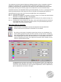
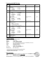
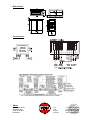
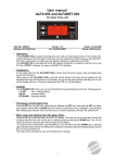
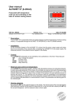
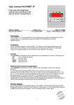
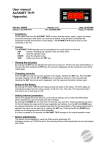
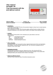
User manual ALFANET 70 Clock Real-time time switch VDH doc. 080424 Software: ALFANET 70 Klok Versie: v1.0 File: DO080424.WPD Datum: 2-4-2008 Range: - * Installation. On the upper side of the ALFANET 70 Clock is shown how the output and power supply should be connected. After power up a self test is started. After the self test is completed the actual time will be shown on the display. The ALFANET 70 Clock can be read-out and adjusted with the PC by using an ALFANET PCINTERFACE * Control. The ALFANET 70 Clock can be adjusted with two keys on the front: prg - up - Activating internal parameters - Selecting parameter number - Raise the parameter value on/off - down - ALFANET 70 Clock on/off - Read out and changing the selected parameter - Lower the parameter value * Switching on and off. By pushing the on/off key for several seconds, the ALFANET 70 Clock can be switched on and off. In the off position the text off appears on the display. * Viewing the status If the controller is in the on position, the dot in the middle from the display will flash as a sign that the clock is running. If the block input is closed, the time will alternate with the ‘–.–‘ code. When the relay is energized, the most right dot will light. If the most right dot is flashing than the relay position is changed by the digital input. If the dot flashes together wit the time dot, the relay is energized in the off position of the the clock. If the most right point flashes alternated with the time dot, the relay is de-energized in the on position of the clock. * Adjusting internal parameters. By pushing the prg key for more than 5 seconds, you enter the 'internal parameter menu'. On the display appears ‘P x’. The required parameter can be selected with the prg key. When the required parameter has been selected, it can be read out by pushing the on/off key. By pushing the up or down key, the value can be changed. If no key is puhed for more than 5 seconds, the ALFANET 70 Clock will return to the parameter selection mode and after another 5 seconds it will return to it’s normal read out. By using the parameters it is possible to program seven switching times for the week. This can be seven switching times within one day or different times for each day of the week. For each switching time the required times should be adjusted. This can be each day, only the working days, only the weekends or on a specific day. If a choice is made for one of the first three options, the switch off type will be automatically the same. F.i. At working days on at 08:00 and off at 17:00. When for switch on point a specific day has been adjusted than it’s also necessary to adjust a specific day for the switch off point. F.i. On at Tuesday at 13:35 and off at Tuesday at 16:00 or on at Wednesday at 15:00 and of at Friday at 09:30. If two switch moments have a overlap than the on position is dominant. This means that f.i. workdays on at 7:30 and off at 16:30, together with Tuesday on at 08:00 and Tuesday off at 20:00 will have the result that the relay will be energized at Tuesday at 07:30 and de-energized at 20:00. The other working days the relay will be energized from 07:30 till 16:30. 1 The weekend is the time between P85/86 and P87/88. Because of this it is possible to start the weekend for example Friday at 15.00 and stop the weekend on Monday at 07.00. It is also possible to use this time for a period which has nothing to do with a weekend but which should have special switching times. Working days are the days which are not the weekend days. Parameters which are not adjustable will be ignored automatically. So if P11=1 (all days) than P13 will be ignored (and all the other days) and if P31=0 (off) than the next parameter will be P41. With parameter 81 the function from the second digital input can be programmed. P81 = 0 The input will be ignored. P81 = 1 During the ‘on’ position, it is possible to switch the relay on or off with the external switch. During the ‘off’ position the relay is de-energized. P81 = 2 During the ‘on’ position the relay is energized and during the ‘off’ position the relay can be switched with the external switch. P81 = 3 Changing the current position from the relay. At the next switching moment it will return to the automatic mode. The input is a pulse contact. The input should be opened and closed again for another position change. * Adjusting with the computer. With this button it is possible to read out and adjust the internal parameters. See the manual from the Alfanet PC-Software for more details. By clicking on this button, the switching times from the clock can be adjusted. The seven switching times are shown with seven colours in the left column. A switching time can be selected by clicking with the mouse at one of the colours. The horizontal lines are getting the colour from the selected section. It also possible to see which section is selected at the colour of the digit from the section and the border from the section is yellow instead of black. The adjusted times are shown at the time axis with the same colours. The weekend can be adjusted at the right side of the window. The weekend is shown with the yellow axis. The function from the buttons are: Open the saved adjustments, save the adjustments, print the adjustments and undo the changes. 2 * Parameters ALFANET 70 Clock ParaMeter 00 01 Description Range Default value Adjust time Adjust day 0 = Monday 1 = Tuesday 2 = Wednesday 3 = Thursday 0:00-23:59 (hh:mm) 0...6 - 0...10 0 4 = Friday 5 = Saturday 6 = Sunday x = 1 till 7 x1 x2 x3 x4 Switch on mode 0 = Off 1 = Every day 2 = Working days 3 = Weekends 4 = Monday 5 = Tuesday Switch on time Switch off day (If x1 >= 4) 4 = Monday 5 = Tuesday 6 = Wednesday 7 = Thursday Switch off time 6 = Wednesday 7 = Thursday 8 = Friday 9 = Saturday 10 = Sunday 0:00-23:59 (hh:mm) 4...10 0:00 4 0:00-23:59 (hh:mm) 0:00 8 = Friday 9 = Saturday 10 = Sunday 80 81 Time correction real time clock Function digital input 0 = Non 1 = Switching on/off during on 2 = Switching on/off during off 3 = Stopping / changing current function -99 .. 99 (min per year) 0..3 0 0 85 0...6 5 88 Start day weekend 0 = Monday 1 = Tuesday 2 = Wednesday 3 = Thursday Start time weekend End day weekend 0 = Monday 1 = Tuesday 2 = Wednesday 3 = Thursday End time weekend 90 95 96 98 Network number Software version Production year/week Serial number 86 87 4 = Friday 5 = Saturday 6 = Sunday 0:00-23:59 (hh:mm) 0...6 0:00 0 0:00-23:59 (hh:mm) 0:00 4 = Friday 5 = Saturday 6 = Sunday 1..250 - * Technical details. Type Range Supply Read out Relay Control Front Inputs Dimension Panel cut out : ALFANET 70 Clock : Week clock : 12Vac 50/60Hz (-5/+10%) : 4-digit 7-segments display : Ry1= SPST(NO)250V/8A (cos =1) of 250V/5A (cos =0.4) : through push buttons on the front. : Polycarbonate IP65 : Contact input-1 (Block) Contact input-2 (Function P81) : 35 x 77 x 71,5mm (hwd) : 28 x 70mm (hw) - Provided with memory protection during power failure. - Connection with screw terminals on the backside. - Equipped with self test function. * Error messages. The following error messages can appear on the display from the ALFANET 70 Clock: EEE - Adjustments are lost. Solution EEE: - Reprogram the settings. Resetting Alarm. If an error message appears it can be reset with the on/off key. 3 1 - * Dimensions. * Connections. * Adres. VDH Products BV Produktieweg 1 9301 ZS Roden Nederland Tel: Fax: Email: Internet: 4 +31 (0)50 30 28 900 +31 (0)50 30 28 980 [email protected] www.vdhproducts.nl