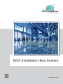
1
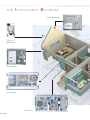
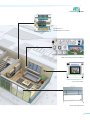
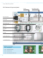
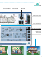
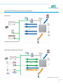
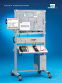
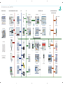
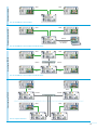
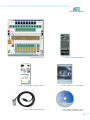
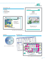
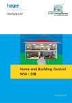
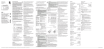
® ELABOTrainingsSysteme Aus- und Weiterbildung GmbH KNX Installation Bus System www.elabo-ts.com K N X I N S T A L L A T I O N B U S S Y S T E M KNX SYSTEMS Configuration and Commissioning KNX Protective measures Installation technology Intercom systems Fire alarm systems Building Control Lighting technology Hazard alarm systems Telecommunication Tra ining systems ® ELABOTrainingsSysteme BASIC FUNCTIONS SWITCHING DIMMING BLINDS AND SHUTTERS BINARY INPUTS Page 6 − 9 PROGRAMMING ETS4 SOFTWARE ALARM CONTROL TOUCH PANEL Page 10 − 15 PROJECTS DIMMING ALARM SYSTEM Page 16 − 19 NETWORKS ETHERNET DALI ETHERNET Page 20 − 35 SENSOR AND ACTUATOR SYSTEMS WEATHER STATION LOGO! BLINDS AND SHUTTERS Page 36 − 41 COURSWARE MANUALS TRANSPARENCY SETS TECHNOCARDS Page 42 − 43 INFORMATION AND CONSULTING Page 44 − 45 K N X I N THE S T A L L A T I O N B U S S Y S T E M I NTELLIGENT B UILDING Project: Alarm functions Weather station Project: Dimming Room Controller Access control 4 ® ELABOTrainingsSysteme PLC Board 24 V with KNX extension module KNX Professional Programming Board Colour Touch Panel Technology model: Blind 5 K N X I N S T A L L A T I O N B U S S Y S T E M HARDWARE KNX Professional Programming Board 41 220 KNX Professional Programming Board LEARNING OBJECTIVES DConfiguring KNX systems DCommissioning and troubleshooting DDocumentation and maintenance Four different templates for exchange 41 220 KNX Professional Programming Board in the DIN A4 system, with the following components: 6 1 KNX power supply 1 USB programming interface 1 binary input, 8-X with 8 simulation switches, manual/automatic operation 1 8-X binary output with manual/automatic operation 1 1-X dimmer actuator, manual/automatic operation 1 4-X KNX push button sensors 1 2-X KNX push button sensors 1 2-X button with 2-X KNX binary input and flush-mounted blind actuator 11 indicator lamps Sockets for onward connection to other systems Industrial blind socket Application examples: Switching: Logic, delay, time, staircase, status Binary input: Switching, edge, cyclical, dimming, blinds Push button sensor: Dimming, switching, edge, blind ® ELABOTrainingsSysteme KNX applications Residential house Administration building 41 221 Consisting of: - Entrance area - Living room - Bedroom - Kitchen / dining room - Office - Hallway 41 222 Consisting of: Recreation centre - Outdoor area - Entrance area - Lobby - 2 office rooms - Recreation rooms Office building with outdoor area 41 223 Consisting of: - Entrance area - Sanitary facilities - Service centre - Billiards room 41 224 Consisting of: - Outer lighting - Staircase - 1 large-area office - 2 individual offices with blinds 7 K N X I N S T A L L A T I O N B U S S Y S T E M HARDWARE KNX Professional Programming Board USB port Mains voltage input Power supply Blind actuator, flush-mounted with 2-X binary input Bus coupler BCU 2 Bus coupler BCU 1 2-X button 2-x push button sensor 4-x push button sensor Templates for exchange 8 41 221 Residential house 41 222 Administration building 41 223 Recreation centre 41 224 Office building with outdoor area Input device, 8 inputs ® ELABOTrainingsSysteme Switching actuator 8-X Dimming actuator Blind socket System plug for connecting the projects 2 simulation switches connected to the inputs of the binary input LEDs and incandescent lamps to simulate the outputs 6 simulation buttons connected to the inputs of the binary input device 9 K N X I N S T A L L A T I O N B U S S Y S T E M SOFTWARE KNX programming environment 90 144 KNX programming environment ETS4 Lite 90 145 KNX programming environment ETS4 Professional LEARNING OBJECTIVES DConfiguring KNX systems DCommissioning and troubleshooting DDocumentation and maintenance KNX programming environment 10 Configuration and commissioning automation solutions in residential and functional buildings Functions for resetting and restoring Full drag & drop functionality Editing feature within the working window Clear display of the parameters Connection with the bus via USB interface, network or internet Reports for project documentation Administration of different project databases Installation requirements: IBM-compatible PC with Windows Vista, Windows 7 or Windows XP, 32 / 64 bit, monitor resolution 1024 x 768 min. 2.0 GHz and 2 GB RAM 20 GB hard disk memory (without projects) USB, RS232 or IP interface, depending on the hardware connection ® ELABOTrainingsSysteme ETS4 Lite and ETS4 Professional The KNX programming environment is used for the planning and configuration of intelligent KNX home and building control. It supports the execution of home and building control projects in the following phases: 1. Configuration 2. Commissioning 3. Project documentation CD-ROM KNX Programming environment 4. Diagnosis and troubleshooting 90 144 KNX programming environment ETS4 Lite The execution of individual projects up to max. 20 devices in a line, with bus access is possible, without any time restriction. For schools and vocational training 90 145 KNX programming environment ETS4 Professional Full software version without any limitation 90 146 KNX programming environment ETS4 Trainer Package 1x ETS4 Professional, 10x ETS4 Lite, 2x Home and Building Control manual For schools and vocational training Accessories 80 544 USB Programming Connection Line 41 002 KNX Professional Connection Line 11 K N X I N S T A L L A T I O N B U S S Y S T E M HARDWARE Alarm Control Board / KNX Interface 45 000 Alarm Control Board 45 010 KNX Interface Board LEARNING OBJECTIVES 45 000 Alarm Control Board DConfiguration and commissioning of a 45 010 KNX Interface Board D Connecting security alarm systems with security alarm system DSelection of suitable detectors and sensors DProgramming of the security alarm system via an LCD display or a PC a KNX system D Forwarding the signals of the security alarm system to the KNX system D Calling up scenes in a KNX system via the DMaintenance work, security alarm system testing the detectors used DUse of different activating devices, selection according to security requirements DCommissioning an access control system DIntegration in a KNX system Technical data, KNX Interface Board KNX interface for connection to the external safety bus All connections on 2mm safety sockets Operating Power supply from the safety bus of the control centre Technical data, Alarm Control Board 12 10 detector groups 2 relay outputs, programmable 1 relay output for continuous alarm 1 internal safety bus 1 external safety bus 1 transistor output for a strobe light 2 transistor outputs for sirens 8 transistor outputs for e.g. a dialler 1 input for an emergency power supply 1 input for telephone dialler Fault 1 input for telephone dialler Alarm 1 input for telephone dialler Sabotage VdS approval: Classes A, B, C in accordance with DIN VDE 0833 parts 1&3 ® ELABOTrainingsSysteme Interface KNX to the intrusion alarm central panel Al er t Outputs only Detector group 01 Detector group 02 Detector group 80 A/ N* -co nn ec tio n Status (A/N*, Alarm, ...) VdS-approved only in this mode Al er t Bidirectional communication (Standard) Detector group 01 Detector group 02 Detector group 80 A/N*-connection Detectors Detector group terminals A/ N* -co nn ec tio n Status (A/N*, alarm, ...) *A/N=activated /non-activated 13 K N X I N S T A L L A T I O N B U S S Y S T E M HARDWARE Touch Panel 41 227 KNX Colour Touch Panel LEARNING OBJECTIVES DControl and visualisation of KNX systems DSwitching DSwitching/dimming with stop telegram DSwitching with forcible control DBlind control DSetting values, 1 byte DSetting temperature value DSetting value counter DCalling/saving scenes 41 227 DSetting heater operating mode D1-bit status display D1-byte status display D2-bytes status display D4-bytes status display DScreen saver DTime and logic functions DPresence simulation KNX Colour Touch Panel The Board contains the following components: 14 KNX Color Touch panel 5,7"-colour TFT Mains and bus voltage connection 10 operating pages with 5 functions each Up to 60 additional functions can be implemented Up to 64 scenes can be stored 16 alarm/event objects available ® ELABOTrainingsSysteme Clear menu guidance on the Touch Panel Conference 1 Office 1 Conference 2 Office 2 Meeting 1 Reception Meeting 2 Kitchen Lobby Hallway Skip to selection of the configuration Activate the silent mode 10:42AM 03/05/10 Skip to alarm screen Start the Logo / slide show Display of the date and time Configuration General General system settings Scenes Configuration of the scenes Logic Configuration of the logic Presence Presence simulation Configuration of the schedules Time schedules Graphs Physical unit of the status value Trending module Temperature [˚C] 30 Discrete indication of the min. and max. values Min: 6.2 ˚C Max: 22 ˚C 22 14 Parameterised scaling for the y-axis Progression of the status value over the parameterised period 6 -2 -10 11 :15 11 :35 11 :55 12 :15 12 :35 12 :55 13 :15 15 K N X I N S T A L L A T I O N B U S S Y S T E M PROJECTS Project: Dimming 41 012 KNX Project Dimming LEARNING OBJECTIVES DSwitching ON/OFF D Dimming (relative and absolute) 0 % – 100 % DIntegration in the scene control D Feedback of the initial state and the initial of the adjustable range D Set dimming value continuously / value via the bus in case of changes DCommissioning and troubleshooting switch on directly 41 012 KNX Project Dimming Set of circuit components for the project Dimming, assembled on a grid panel, consisting of: Small-scale distributor Halogen lamp 60 W, incl. bulb RCD circuit breaker 40/0.03 A, 4-pole Set of KNX system cables with branching and connecting cables Line circuit breaker B10 A, 1-pole Set of wiring and distribution accessories Universal dimming actuator, 2-X, 300 W Scene and logic module Electronic ballast for halogen lamps with recessed 50 W luminaire, in a system casing Binary input 2-X with 2-X push button 16 4-X push button sensor with bus coupler and base ® ELABOTrainingsSysteme Dimming by means of universal dimming actuators Sinusoidal voltage Phase angle control, leading edge Phase angle control, trailing edge 230 V 50 Hz Voltage progression at the load Voltage progression at the load 325 V 325 V 10 ms - 325 V 325 V 10 ms 20 ms - 325 V 10 ms 20 ms 20 ms - 325 V Dimming by means of universal dimming actuators L1 L2 L3 N Connection of an incandescent lamp load to the universal dimming actuator 17 K N X I N S T A L L A T I O N B U S S Y S T E M PROJECTS Project: Alarm functions 41 014 KNX Project Alarm functions LEARNING OBJECTIVES DConfiguring KNX signalling systems DIntegrating sensors of alarm technology DPutting telephone gateway into operation DEvaluating and monitoring alarm signals DParameterisation of an LCD display DCommissioning and troubleshooting 41 014 Project alarm function KNX Set of circuit components for the project Dimming, assembled on a grid panel, consisting of: 18 Analogue telephone gateway analogue with web server − Power supply 12 V DC Distribution − small-scale distributor Detectors and sensors − Reed contacts for door and window monitoring − Infrared motion detector − Glass breakage sensor − Alarm distributor with sabotage monitoring − KNX detector group terminal KNX 12 V DC with 2 detector group inputs for several passive detectors − KNX LCD display for displaying alarm states and for parameterising values − Set of KNX system cables with branching and connecting cables − Set of wiring accessories ® PROJECT: ALARM FUNCTIONS ELABOTrainingsSysteme ELABOTrainingsSysteme 19 K N X I N S T A L L A T I O N B U S S Y S T E M HARDWARE KNX network coupler 41 020 KNX network coupler LEARNING OBJECTIVES DUsing line/area couplers DParameterising line/area couplers DUsing filter tables DEvaluating routing counter contents DCommissioning and troubleshooting DLine/area coupling via IP DProgramming via IP 41 020 KNX network coupler Set of circuit components for the project Dimming, assembled on a grid panel, consisting of: 20 KNX Power supply 2 line/area couplers 1 IP router Power supply 24 V DC Push button sensor with LCD display and timer function Distribution panels for lines A and B Free mounting space for additional sensor ® COUPLIN G L I N ES V I A E TH E R N E T ELABOTrainingsSysteme Commissioning via LAN / W-LAN Procedure W-LAN (wireless) KNX Connect the IP router to the KNX bus. Use the Ethernet cable to connect the W-LAN router to the IP router. You can now go into the individual rooms with a notebook and the ETS software. LAN (Ethernet cable) W-LAN router IP router KNX device Notebook (W-LAN-capable) Advantages KNX device KNX device Wireless KNX commissioning via W-LAN Freedom of movement in the building Commissioning possible by only one person Remote access over the Internet (DSL) Procedure KNX DSL router with VPN or ISDN-/analoguedial-in router LAN IP router 1. Connect the IP router to the KNX bus 2. Connect the IP router to the LAN 3. Configure the VPN-DSL router or the dial-in router Internet (via VPN-connection or dial-in modem) KNX device DSL router or modem KNX device Advantages LAN KNX device Parameters can be quickly changed via remote access Cost reduction through remote access (physical approach not required) Guarantee of data security Coupling lines over Ethernet (LAN) Procedure KNX LAN (multicast-capable) IP router KNX IP router KNX device KNX device 1. Connect the IP router to each KNX line (instead of a line coupler) 2. Connect IP router via multicast-capable LAN 3. Commission each IP router with the ETS3 or ETS4 software as you would do with a "conventional" line/area coupler KNX device Advantages KNX device LAN as main and sub-area line Data transfer over longer paths possible Use of existing data networks and components (LAN) 21 F R O M I N S T A L L A T I O N T E C H N O L O G Y. . . ® ELABOTrainingsSysteme . . . TO BU I L D I N G C O M M U N I C AT I O N K N X I N S T A L L A T I O N B U S S Y S T E M ® NETWORKED BUILDING CONTROL ELABOTrainingsSysteme INSTALLATION TECHNOLOGY AUDIOVISUAL TELECOMMUNICATION SYSTEMS HOME BUS ISDN KNX LIGHTING TECHNOLOGY / DALI ALARM SYSTEMS / FIRE ALARM SYSTEMS SAFETY BUS / ACCESS CONTROL Installation Switch Board I Video Outdoor Station Door Phone Weather station KNX Programming Board KNX network coupler Fluorescent Lamps Boards A and B Detector Circuits Board 1st line Video Power Supply Board ISDN Board + KNX LOGO! KNX Programming Board Gateway Room Controller Energy Saving Lamps Board Keypad Board LAN Interface Board High-Pressure Sodium Lamp Board LED Effect Lighting Board Interface Board Fire Detector Board Alarm Control Board Technical Alarm Board Access control Burglar Alarm Board Intercom Main System Video Indoor Station Main line TAE Connection Board Network analysis Project: Dimming Colour Touch Panel Intercom Sub System Audio Indoor Station Telephone ISDN Fault Simulator Metal Halide Lamp Board Project: Alarm system Set of house intercom and signalling systems consisting of: 1 outer station and 2 inner stations ISDN tester LED Lamps Board S0-Bus Extension Board Project: Blinds FAX machine LED Control Board K N X I N S T A L L A T I O N B U S S Y S T E M ® NETWORKED BUILDING CONTROL ELABOTrainingsSysteme INSTALLATION TECHNOLOGY AUDIOVISUAL TELECOMMUNICATION SYSTEMS HOME BUS ISDN KNX LIGHTING TECHNOLOGY / DALI ALARM SYSTEMS / FIRE ALARM SYSTEMS SAFETY BUS / ACCESS CONTROL Installation Switch Board I Video Outdoor Station Door Phone Weather station KNX Programming Board KNX network coupler Fluorescent Lamps Boards A and B Detector Circuits Board 1st line Video Power Supply Board ISDN Board + KNX LOGO! KNX Programming Board Gateway Room Controller Energy Saving Lamps Board Keypad Board LAN Interface Board High-Pressure Sodium Lamp Board LED Effect Lighting Board Interface Board Fire Detector Board Alarm Control Board Technical Alarm Board Access control Burglar Alarm Board Intercom Main System Video Indoor Station Main line TAE Connection Board Network analysis Project: Dimming Colour Touch Panel Intercom Sub System Audio Indoor Station Telephone ISDN Fault Simulator Metal Halide Lamp Board Project: Alarm system Set of house intercom and signalling systems consisting of: 1 outer station and 2 inner stations ISDN tester LED Lamps Board S0-Bus Extension Board Project: Blinds FAX machine LED Control Board N X I N S T A L L A T I O N B U S S Y S T E M ® LINE COUPLER ELABOTrainingsSysteme Classical topology f In the classical topology, all the line and area coupLine/area coupler N140 for area and line coupling 1.5.0 Line 1.5 LK 2.4.0 LK 1.2.0 Line 1.2 LK Level 3 Level 2 2.3.0 Main line 2.0 Main line 1.0 LK Line 2.3 2.2.0 Line 2.2 LK 2.1.0 LK KNX BK Area 2 (east wing) BK Area line 0. 1.0.0 Line 2.1 LK Level 1 Area 1 (west wing) This topology is proven and used extensively. The bus line lengths are mostly limited to one building. LK 1.1.0 Line 1.1 Line 2.4 LK Level 4 1.3.0 Line 1.3 Line 2.5 LK Level 5 1.4.0 Line 1.4 lers are traditionally configured as KNX couplers. 2.5.0 2.0.0 Modern topology f In this modern topology, the area couplers are replaced by IP routers X. IP-router N146 as an area coupler 1.5.0 Line 1.5 2.5.0 LK 1.4.0 2.4.0 LK Line 1.3 LK 1.2.0 Line 1.2 LK Level 3 Level 2 2.3.0 2.2.0 Line 2.2 LK BK 1.0.0 Even other media like fibre optic cables or W-LAN can be employed to couple to remote buildings and to exchange group address telegrams. Area 2 (east wing) BK Data network (LAN) Line 2.1 LK Level 1 KNX Area 1 (west wing) Line 2.3 2.1.0 LK Owing to the use of standard network components, the connection of e.g. two parts of a building is not limited to bus line lengths. LK 1.1.0 Line 1.1 Line 2.4 LK Level 4 1.3.0 Main line 2.0 Line 1.4 Line 2.5 LK Level 5 Main line 1.0 K 2.0.0 X Innovative topology f In this innovative topology, all the line couplers are replaced by IP routers Y. IP router N146 as a line coupler 1.5.0 Line 1.5 LK 2.5.0 Level 5 1.4.0 Line 1.4 LK 2.4.0 Level 4 1.3.0 Line 1.3 LK LK LK Line 2.3 LK Line 2.2 LK 2.1.0 Level 1 Area 1 (west wing) Line 2.1 LK Area 2 (east wing) Data network (LAN) Y 28 LK 2.2.0 Level 2 1.1.0 Line 1.1 Line 2.4 2.3.0 Level 3 1.2.0 Line 1.2 Line 2.5 LK The use of area couplers is not necessary any more. This configuration allows connecting every individual floor via Ethernet (LAN) and using existing LAN networks. Moreover, through the correct configuration of the IP router, large projects can be commissioned more clearly and easily in the form of smaller individual projects. An exchange of group address telegrams is possible despite the division into individual projects. KNX KNX KNX Line area coupling KNX Commissioning via LAN Use of the KNX line / area couplers TCP/IP Programming via TCP/IP Use of the KNX line / area couplers and the IP router Area line via TCP/IP KNX Switch KNX KNX TCP/IP KNX Use of the KNX line / area couplers and the IP router KNX KNX Line coupler via TCP/IP TCP/IP KNX TCP/IP KNX Use of only the IP routers 29 K N X I N S T A L L A T I O N B U S S Y S T E M KNX NETWORK COUPLER Line / area coupler 1 Power supply Connection of main line Mains voltage input Distribution panel 1 Distribution panel 2 Area Power supply Connection of area line 1 Connection of area line 2 30 ® ELABOTrainingsSysteme Line / area coupler 2 IP router Power supply for IP router Distribution panel 1 Push button panel 3-X with LCD display and timer function up to 40 weekly timer entries 8 switching functions possible Ethernet connection for IP router Connection KNX line 31 K N X I N S T A L L A T I O N B U S S Y S T E M HARDWARE KNX Gateway FUNCTIONS DTime functions: Timer mode Night mode Warning of impending OFF DDimming: Brighter/darker Brightness limitation Adjustable dimming time DSwitching: On/Off On/Off via dimming DEmergency lighting: Control of self-contained luminaires Support of obligatory test sequences DStatus: short-circuit power supply 41 226 KNX Gateway Status outputs Status groups Status electronic ballast Technical data 32 interface for integrating of up to 64 devices bus voltage: approx. 19 V DC KNX-bus connection Mains voltage: 110 − 240 V AC, 50/60 Hz Connection of all inputs and outputs via safety sockets (2 mm) ® W H AT I S DA L I ? ELABOTrainingsSysteme Innovation in lighting technology Digital Addressable Lighting Interface DALI was jointly created by the leading manufacturers of control units and electronic control gears as a non-proprietary standard to satisfy all the demands that are placed on a modern light management. Approved by almost all luminaire and control equipment manufacturers, DALI has become the new standard in lighting industry. DALI was designed mainly for room lighting control. Ease of use of the lighting systems and their components has always been in the focus. As an interface standard, DALI provides the means to configure complete light management systems for rooms such as DALI room controllers or KNX-DALI gateways. Innovation in lighting technology FEATURES Simple installation DALI and power supply wires can be handled in a single, common cable. Any wiring topology can be used, such as line, star or mixed. Stable dimming function Precise dimming values are achieved from digital signals which are insensitive to interferences. Flexibility The assignment of the luminaires to the light groups and the operating buttons are defined after the installation, thus offering easy planning even after start-up. The configuration of situation-dependent light settings requires lighting systems allowing to group luminaires and to save the light values of individual groups as light scenes. There are further requirements for the integration of lighting systems in building management with centralized switch control and status reporting. Polarity of wiring irrelevant Benefit for installers Changing the use of a room does not require rewiring as in 1…10 V systems. The complete lighting can be software-controlled over a single gateway. DALI is bus-capable Wiring errors can almost be excluded. Light switching and dimming is only one function of DALI. It can also be used to control colourful light scenes, fluorescent lamps or metal halide lamps. DALI furthermore allows complex programming for setting up constant light control circuits. 33 K N 34 X I N S T A L L A T I O N B U S S Y S T E M ® ELABOTrainingsSysteme ELABOTrainingsSysteme 35 K N X I N S T A L L A T I O N B U S S Y S T E M HARDWARE KNX weather station LEARNING OBJECTIVES DRecording and evaluation of weather data DTemperature monitoring D Evaluation of the brightness e.g. for constant light regulation DBrightness-dependent lighting control D Wind monitoring e.g. for controlling blinds D Time recording via DCF 77 and transmission to the bus DLogical connection of signals DFacade control of blinds or roller shutters DEvaluation of rain alarms or precipitation 41 022 KNX weather station 41 022 KNX weather station V Wind [m/s] 36 Power supply 12 V DC Rain simulation button Continuously variable wind simulation Weather station with − Rain sensor − Wind sensor − Temperature sensor − DCF 77 receiver − Light sensor − Facade control − Logic function/timer 16,1 10,6 Wind alarm (Shutters M2) Wind sensor Wind limit value 2 (Fabric awning M1) Awning (M1) (Shutters M2) ® ELABOTrainingsSysteme Evaluation of the different sensors Precipitation sensor with wind limit value for fabric awning OR Actuator for awning Wind limit value 2 Precipitation sensor, digital Wind sensor Brightness sensor Temperature sensor Value range: 0/1 Address: Building no: 31 Name: Value range: 0 – 70 m/s Building no: 7 Value range: 0 – 99 Lux Building no: 16 Value range: Building no: -40 – +80° C 33 Address: Name: Address: Name: Address: Name: 3/6/31 Precipitation alarm 3/6/7 Wind speed [m/s] 16 bit 3/6/16 Brightness [Lux] 16 bit 3/6/33 Outside temperature [°C/F] 16 bit Definition of different limit values [kLux] [Lux] Brightness sensor 20 Address: 20 Sunshine Object number 150 26 Object number 3/6/20 Address: Name: 3/6/26 Darkness Brightness limit value 1 (awning) Twilight sensor Twilight limit value 1 (blind) 37 K N X I N S T A L L A T I O N B U S S Y S T E M LO G O ! PLC Board with LOGO! and KNX 40 016 LOGO! PLC Board 24 V with KNX Expansion Module 40 026 LEARNING OBJECTIVES DParameterising logic modules DFundamentals of digital technology DProgramming with the operating elements DProgramming with the PC 40 016 PLC Board 24 V LOGO! 24RC: 38 Integrated display panel with backlighting and operating panel with buttons Memory EPROM for switching program and internal set values 8 inputs (of which 4 are usable analogously): 0...10 V 4 relay outputs 10 A max. (– 10 A with resistive load – 3 A at inductive load) Short-circuit protection: via external fuse 8 integrated timers with summer/winter time switching Power reserve approx. 80 hours Modularly expandable Mounted on PLC Board 40 014 ® ELABOTrainingsSysteme 40 014 PLC Board 24 V 40 026 KNX Expansion Module 63 526 24 V DC Power Supply Board 2.5 A E40 804 Industry user manual LOGO! 40 029 LOGO! USB interface cable 40 808 Software LOGO!Soft Comfort Training and programming software 39 K N X I N S T A L L A T I O N B U S S Y S T E M T E C H N O LO G Y M O D E L Blind 41 115 Technology model, Blind Table model of a blind in a transport frame. Connection is achieved via a common blind or roll-down shutter actuator. The following functions are possible with the technology model 'Blind': Blind movement Slat adjustment Positioning Safety function Technical data 40 Operating voltage 230 V AC Connection to blind socket Connecting cable approx. 1 m Dimensions: 800 x 640 x 120 mm (B x H x T) ® ELABOTrainingsSysteme Weather-dependent blind control B Blind KNX weather station KNX Professional Programming Board 91 801 Experiment case for mobile use KNX Colour Touch Panel 41 K N X I N S T A L L A T I O N B U S S Y S T E M COURSEWARE Manual contents Project-oriented training Principles KNX Toolsoftware Version 4.x (ETS4.x) Tests for basic building functions Project 1: Breaker circuit, button switched line, dimming and blind function Project 2: Extension with a time function Project 3: Breaker circuits, dimming, blind control with central OFF, use of feedback objects Project 4: Control of building functions in a recreation centre; lighting control, blind control dimming, logical connectives and time function Project 5: Office building with safety function for the blind and logical connective OR Practical experiments Practical experiments for the trainee or the student equal to the trainer part, with tasks, but without solutions. Printed and digital! ® Instructor's Edition 42 ELABOTrainingsSysteme Student Edition ELABOTrainingsSysteme KNX KNX Installation Bus system Installation Bus system Instructor's Edition Student Edition Version 4.1 – Cat. no. E41 235 Version 4.1 – Cat. no. E41 236 KNX Installation Bus system KNX Installation Bus system E41 235CD Manual, Trainer Part KNX E41 236CD Manual, Practical Experiments KNX ® ELABOTrainingsSysteme Transparency set ® Principles Applications KNX Toolsoftware Example solutions Components Transparency set ELABOTrainingsSysteme KNX European Installation Bus system KNX Zielsetzungen KNX objectives Tasks of KNX: Aufgaben der KNX: of products - Certification =HUWLIL]LHUXQJYRQ3URGXNWHQ - and training centres XQG6FKXOXQJVVWlWWHQ trade marks Assigning :DUHQ]HLFKHQYHUJHEHQ Assuring quality 4XDOLWlWVLFKHUQ Securing compatibility (EIS) .RPSDWLELOLWlWJDUDQWLHUHQ(,6 Uniform standard KNX (LQKHLWOLFKHU6WDQGDUW.1; Transparency set Version 4.1 – Cat. no. E41 237 ELABO7UDLQLQJV6\VWHPH ELABO7UDLQLQJV6\VWHPH Aus- und Weiterbildung GmbH 1 E41 237CD Set of transparencies KNX Software TECHNOCard Database collection Lage, Funktion emente und Anzeige der Bedienel Taster 2-fach / Taster USB Schnittstelle Lage der Anzeige und abegerät Bedienelemente Binäreing Lage der Anzeige und Lage der Anzeige und ktor Bedienelemente Jalousiea 4-fach KNX/EIB Spannungsversorgung N125/01 E41 210 KNX database collection tor Bedienelemente Schaltak KNX/EIB KNX/EIB Schaltaktor 8-fach Binäreingabegerät 8-fach Dimmaktor (2Amp) N263E01Lage der Anzeige und BedienelementeN567/12 KNX/EIB Dimmaktor N528/31 2 Simulationsschalter angeschlossen an die Eingänge des Binäreingangs S7-G, S8-H Jalousienbuchse 230V KNX/EIB Systemstecker zum Anschluss der Projekte KNX/EIB USB-Schnittstelle N148/11 Busankoppler BCU 2 UP114 6 Simulationstaster angeschlossen an die Eingänge des Binäreingabegeräts S1-A S2-B S3-C S4-D S5-E S6-F Busankoppler BCU 1 UP110 KNX/EIB 4-fach Tastsensor UP287 DELTA style ® KNX/EIB 2-fach Tastsensor UP286 DELTA style 2-fach Taster KNX/EIB Jalousieaktor UP520/31 mit 2-fach Binäreingang Anzeigefeld Aus- und Weiterbildung GmbH 4.2 Programmier-LED ACHTUNG! ELABOTrainingsSysteme Im Hüttental 11 85125 Kinding - Germany Tel.: + 49 (0) 84 67 / 84 04 - 0 Fax: + 49 (0) 84 67 / 84 04 44 E-mail: [email protected] www.elabo-ts.com Programmiertasten TECHNOCard ® KNX/EIB Professional Programming Board Beachten Sie beim Aufbau und bei der Erprobung der Anlage alle erforderlichen Sicherheitsbestimmungen, die Laborordnung und die erforderlichen Schutzmaßnahmen! 41 233 E41 233 KNX Professional Programming Board 43 K N X I N S T A L L A T I O N B U S S Y S T E M I N F O R M A T I O N A N D C O N S U LT A T I O N CONSULTANCY Design of customer oriented solutions Presentation, product demonstration and on-site consultation Assistance in the choice of products complying with syllabuses Customized products according to requirements Development of room concepts Design of ergonomic workplaces Turnkey projects CONTACT ELABOTrainingsSysteme GmbH Service-Center Im Hüttental 11 85125 Kinding / Germany Tel.: + 49 (0) 84 67 / 84 04 - 0 Fax: + 49 (0) 84 67 / 84 04 44 [email protected] www.elabo-ts.com 44 ® ELABOTrainingsSysteme EXPERIENCE Design and manufacturing of technical training systems Comprehensive range of innovative products, systems and solutions – MADE IN GERMANY Quality service from first consultation to delivery and beyond Trainer seminars onsite or inhouse References worldwide - Industrial training institutions - Vocational schools / technical schools - Chambers of crafts - Technical colleges - Universities / Universities of Applied Sciences WE ASSIST YOU On-site installation and commissioning Technical support Warranty and maintenance Briefing and training Qualification, advanced training, workshops Comprehensive product documentation Detailed courseware for trainers and students 45 K N 46 X I N S T A L L A T I O N B U S S Y S T E M ® YO U R I N Q U I RY ELABOTrainingsSysteme ELABOTrainingsSysteme Aus- und Weiterbildung GmbH Im Hüttental 11 85125 Kinding / Germany Tel.: +49 (0) 84 67 / 84 04 - 0 Fax: +49 (0) 84 67 / 84 04 44 Name, Position Company / Institution / Government agency Street, Post Box ZIP Code, City, Country Telephone Fax We would like to be contacted: Fby telephone Fby e-mail E-Mail Copy and fax Subject to technical modifications and further developments 07 / 2012 FPlease send us an offer: Ord.-No Description / Title Page 41 220 KNX Professional Programming Board 41 221 Application – residential house 7 41 222 Application – administration building 7 41 223 Application – recreation room 7 41 224 Application – office building with outdoor area 7 90 144 KNX-Programming environment ETS4 Lite 11 90 145 KNX-Programming environment ETS4 Professional 11 80 544 USB Programming Connection Line 11 41 002 KNX Professional Connection Line 11 45 000 Alarm Control Board 12 45 010 KNX Interface Board 12 41 227 KNX Colour Touch Panel 14 41 012 Project: Dimming 16 41 014 Project: Alarm function 18 41 020 KNX-Network Coupler 20 41 226 KNX Gateway 32 41 022 KNX Weather Station 36 40 016 PLC Board 24 V 38 40 026 KNX Expansion Module 39 63 526 24 V DC Power Supply Board 39 40 804 Industry user manual LOGO! 39 40 029 LOGO! USB interface cable 39 40 808 Training and programming software LOGO!Soft Comfort 39 41 115 Technology model: Blind 40 91 801 Experiment case 41 41 235CD Manual, Trainer Part, KNX 42 41 236CD Manual, Practical Experiments KNX 42 91 905 Set of media folders including register 42 41 237CD Set of transparencies KNX 43 41 233 TECHNOCard KNX Professional Programming Board 43 41 210 KNX database collection 43 Qty 6 47 K N X I N S T A L L A T I O N B U S S Y S T E M ® ELABOTrainingsSysteme ELABO TrainingsSysteme GmbH Im Hüttental 11 85125 Kinding / Germany Tel.: +49 (0) 84 67 / 84 04 - 0 Fax: +49 (0) 84 67 / 84 04 44 E-mail: [email protected] Internet: www.elabo-ts.com