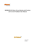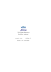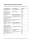
1
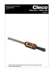
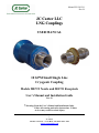
Manual P/N C01341
Rev. B
JC Carter LLC
LNG Couplings
USER MANUAL
10 GPM Small Single Line
Cryogenic Coupling
Models 50E722 Nozzle and 50E721 Receptacle
User’s Manual and Installation Guide
Rev. B
! Warning: Read the User’s Manual and Installation Guide.
Follow all warning and safety instructions. Failure
to do so may result in serious injury.
1
JC C arter
671 West 17th Stre et • C osta Mesa, C A 92627-3605 • USA
www.jc c arternozzles.c om
Manual P/N C01341
Rev. B
Introducing the JC Carter LNG Couplings
Thank you for selecting JC Carter LNG Couplings.
JC Carter Couplings offer the following features:
x
x
x
x
x
x
x
x
! Attention:
Diametrical seals prevent liquid leakage while refueling
No nitrogen purging is required for proper operation
Couplings are easy to use and maintain
Unique, freeze-free fueling allows removal of nozzle
from the receptacle under most weather conditions
Simple hose and line connections
Safety features prevent fuel flow while couplings are
disconnected
Durable design protects against damage in the field
Extensive life-cycle testing has shown the coupling to
be reliable and long-lasting
This symbol will be used to point out important safety instructions.
Please read this manual carefully before using couplings.
2
JC C arter
671 West 17th Stre et • C osta Mesa, C A 92627-3605 • USA
www.jc c arternozzles.c om
Manual P/N C01341
Rev. B
Warnings and Safety Instructions
! Operator Safety:
1. Always wear protective clothing consisting of the following:
x Full face shield
x Thermal gloves rated for cryogenic use
x Cryogenic smock
x Solid shoes capable of withstanding cryogenic spillage
2. Read the User’s Manual and Installation Guide completely before operating
coupling.
3. Keep area of operation clear of all persons other than operator.
4. Use coupling only as described in this User’s Manual, failure to do so may result
in serious injury.
5. Do not use any attachments or accessories with coupling not supplied by JC
Carter.
6. Do not operate coupling if damage has occurred. If damage has occurred use
only JC Carter or JC Carter’s approved source for repairs.
7. Maintenance and repairs should be done only by trained personnel using genuine
JC Carter supplied replacement parts. Failure to comply will void the JC Carter
warranty and exclude JC Carter from any responsibility.
3
JC C arter
671 West 17th Stre et • C osta Mesa, C A 92627-3605 • USA
www.jc c arternozzles.c om
Manual P/N C01341
Rev. B
Contents
Title
Page
Description
5
Installation Tools and Accessories
6
Specifications
7
Nozzle Installation
8
Receptacle Installation
10
Operating Instructions
12
Maintenance Schedule
14
4
JC C arter
671 West 17th Stre et • C osta Mesa, C A 92627-3605 • USA
www.jc c arternozzles.c om
Manual P/N C01341
Rev. B
Description
The Refueling Nozzle:
JC Carter model 50E722 is the nozzle half of the liquefied natural gas (LNG) coupling.
The single line cryogenic nozzle is intended for use in no-vent LNG fuel systems.
Features of this nozzle include an independent shut-off valve located in the flow path
within the nozzle. To refuel the LNG fueled vehicle, the operator mates the nozzle with
the receptacle located on the vehicle and turns the nozzle ¼ turn in the clockwise
direction. This process also beings the flow of the fuel through the coupling. By rotating
¼ turn in the counter clockwise direction, the operator terminates the flow and unlocks
the nozzle from the receptacle.
The Refueling Receptacle:
JC Carter model 50E721 is the mating receptacle portion of the LNG fueling coupling.
The receptacle mounts on the LNG fueled vehicle, and the nozzle mates with it to refuel
the vehicle. The receptacle contains an independent primary shut-off valve.
5
JC C arter
671 West 17th Stre et • C osta Mesa, C A 92627-3605 • USA
www.jc c arternozzles.c om
Manual P/N C01341
Rev. B
Installation Tools and Accessories
Tools:
Pipe Wrench 1 Ea.
Adjustable Wrench 2 Ea.
Accessories:
Pipe sealant AR
Straight Adapter, ½” Pipe to Tube 1 Ea.
1-5/16” – 12 Jam Nut Supplied with Receptacle 1 Ea.
Washer Supplied with Receptacle 1 Ea.
6
JC C arter
671 West 17th Stre et • C osta Mesa, C A 92627-3605 • USA
www.jc c arternozzles.c om
Manual P/N C01341
Rev. B
Specifications
! Caution: Failure to adhere to the specification limits of this coupling may result in
injury.
Fluid Compatibility: LNG, Methane and LN2
Maximum Refueling Pressure: 250 psig
Maximum Working Pressure: 500 psig
Burst Pressure: 1500 psig
Rated Flow: 10 Gallons per Minute
Receptacle Weight: 0.4 Lbs
Nozzle Weight: 1.2 Lbs
Operating Temperature: -320°F to +120°F
Storage Temperature: -60°F to + 120°F
Spillage on De-Mating: < 1cc
Leakage While Fueling: None
7
JC C arter
671 West 17th Stre et • C osta Mesa, C A 92627-3605 • USA
www.jc c arternozzles.c om
Manual P/N C01341
Rev. B
Nozzle Installation
Step 1:
! Caution: Open nozzle package only in a dry, protected area. Do not allow water or
other contaminants to enter the internal mechanism of the coupling.
Purge the LNG system fill line with gaseous Nitrogen to remove any contamination or
water that may reside in the LNG system fill line.
Step 2:
Remove the nozzle from the sealed shipping bag and the shipping plug from the nozzle
port. Wrap Teflon tape in the clockwise direction on the straight adapter (2 revolutions).
Thread the straight adapter into the nozzle port, torque the adapter to 40-50 ft-lbs.
! Caution: Failure to remove contaminants or moisture may affect the performance
of the LNG coupling.
8
JC C arter
671 West 17th Stre et • C osta Mesa, C A 92627-3605 • USA
www.jc c arternozzles.c om
Manual P/N C01341
Rev. B
Step 3:
Thread the female station hose termination onto the straight adapter; torque the
connection to 115-125 ft-lbs.
Step 4:
! Caution: This step is critical in assuring the safe performance of the LNG coupling.
Perform leak test of the LNG coupling, filling hose and adapters by pressurizing the
upstream side of the filling station hose to 250 psig with Nitrogen gas. Verify the system
is free from any leakage.
9
JC C arter
671 West 17th Stre et • C osta Mesa, C A 92627-3605 • USA
www.jc c arternozzles.c om
Manual P/N C01341
Rev. B
Receptacle Installation
Step 1:
! Caution: Open receptacle packaging only in dry, protected area.
Do not allow
water or other contaminants to enter the internal mechanism of this
coupling.
Remove the receptacle from the sealed packaging and remove the shipping plug from the
receptacle outlet port. Mount the receptacle in the receptacle housing on the vehicle
using the lockwasher and jam nut; torque the jam nut to 40-50 ft-lbs.
10
JC C arter
671 West 17th Stre et • C osta Mesa, C A 92627-3605 • USA
www.jc c arternozzles.c om
Manual P/N C01341
Rev. B
Step 2:
Wrap Teflon tape around the male threaded termination of the vehicle fuel line (2
rotations). Thread the vehicle fuel line onto receptacle port; torque the connection to
115-125 ft-lbs.
The following figure illustrates the clearance needed to allow proper nozzle to receptacle
connection. Select an appropriate location to mount the receptacle based on the envelop
definition figures. Combined nozzle/receptacle dimensions are shown below.
11
JC C arter
671 West 17th Stre et • C osta Mesa, C A 92627-3605 • USA
www.jc c arternozzles.c om
Manual P/N C01341
Rev. B
Operating Instructions
! Caution: The operator must wear the protective clothing outlined in the Warnings
and Safety Instructions on page three (3) of this manual. Failure to do so
may result in injury. Never point the nozzle directly at yourself or
others at anytime.
Step 1:
Put on the following protective clothing:
x Full face shield
x Thermal gloves rated for cryogenic use
x Cryogenic smock
x Solid shoes capable of withstanding cryogenic spillage
Step 2:
If this is the first fueling of the day, check to be sure no fuel pressure is present at the
nozzle. Then wipe out the mating end of the nozzle using a clean, dry cloth.
Step 3:
Insert the nozzle into the receptacle far enough for the locking pins on the receptacle
mechanism to engage with the slots on the nozzle.
Step 4:
Rotate the nozzle by hand ¼ turn clockwise to start fueling.
! Caution: Before removing the nozzle from the receptacle, the LNG supply should
be turned off.
Step 5:
To stop fueling rotate the nozzle by hand ¼ turn counter clockwise and remove the
nozzle from the receptacle.
12
JC C arter
671 West 17th Stre et • C osta Mesa, C A 92627-3605 • USA
www.jc c arternozzles.c om
Manual P/N C01341
Rev. B
Step 6:
Close the cover on the receptacle box, or replace the protective dust cap. Store the nozzle
in a protected location.
13
JC C arter
671 West 17th Stre et • C osta Mesa, C A 92627-3605 • USA
www.jc c arternozzles.c om
Manual P/N C01341
Rev. B
Maintenance Schedule
Please note that JC Carter recommends the following maintenance schedule be followed
to ensure trouble free operation and maximum life. Failure to follow the schedule may
result in less than optimal performance or reduced operating life. All kits described in
this section may be ordered by contacting JC Carter directly at +1 (949)764-2200.
Daily Maintenance:
At the start of each fueling day:
x Check to be sure no pressure is present in the nozzle
x Clean out the mating end of the nozzle with a clean, dry cloth.
Each Fueling:
Before each fueling:
x Clean out the cup of the receptacle with a clean dry cloth.
3 Months or 9,000 Fuelings:
Remove and replace the nozzle retaining rings, nozzle seals, and nozzle seal retainers.
36,000 Fuelings:
Perform 36,000 fuelings repair as well as replacing all nozzle linkage bushings. Use only
JC Carter parts.
14
JC C arter
671 West 17th Stre et • C osta Mesa, C A 92627-3605 • USA
www.jc c arternozzles.c om