1
Copyright Information
Copyright Notice
Copyright © 1997 - 2012 Abroham Neal LLC All Rights Reserved.
Portions of the software described in this document Copyright © Microsoft
Corporation. All Rights Reserved.
Information in this document is subject to change without notice. The software described in this
document is furnished under a single user license agreement. The software may be used only in
accordance with the terms of that agreement. No part of this document and any of the files
furnished as part of this software may be reproduced, stored in a retrieval system, or transmitted in
any form or any means electronic or mechanical, including photocopying and recording for any
purpose other than the purchaser’s personal use without the written permission of Scientific
Solutions, Inc.
DXbase is a trademark of Abroham Neal LLC.
PacketCluster is a trademark of Pavillion Software.
License Agreement
END USER LICENSE AGREEMENT FOR Scientific Solutions, Inc. software
By installing the SOFTWARE PRODUCT, you acknowledge that you have reviewed and accepted the terms of
this End User License Agreement.
IMPORTANT—READ CAREFULLY: This Scientific Solutions, Inc. End User License
Agreement (“EULA) is a legal agreement between you (either an individual or a single entity) and
Scientific Solutions, Inc. for the Scientific Solutions, Inc. software product “DXbase 2007, which
includes computer software and associated media and printed materials, and may include “online
or electronic documentation (“SOFTWARE PRODUCT or “SOFTWARE). By installing,
copying, or otherwise using the SOFTWARE PRODUCT, you agree to be bound by the terms of
this EULA. If you do not agree to the terms of this EULA, promptly return the unused
SOFTWARE PRODUCT to the place from which you obtained it for a full refund.
1
SOFTWARE PRODUCT LICENSE
The SOFTWARE PRODUCT is protected by copyright laws and international copyright treaties,
as well as other intellectual property laws and treaties. The SOFTWARE PRODUCT is licensed,
not sold.
1
GRANT OF LICENSE. This EULA grants you the following rights:
·
Software. You may install and use one copy of the SOFTWARE PRODUCT, or in its
place, any prior version for the same operating system, on a single computer. The primary user of
the computer on which the SOFTWARE PRODUCT is installed may make a second copy for his
or her exclusive use on either a home or portable computer.
·
Storage/Network Use. You may also store or install a copy of the SOFTWARE
PRODUCT on a storage device, such as a network server, used only to install or run the
SOFTWARE PRODUCT on your other computers over an internal network; however, you must
acquire and dedicate a license for each separate computer on which the SOFTWARE PRODUCT
is installed or run from the storage device. A license for the SOFTWARE PRODUCT may not be
shared or used concurrently on different computers.
2
DESCRIPTION OF OTHER RIGHTS AND LIMITATIONS.
·
Limitations on Reverse Engineering, Decompilation, and Disassembly. You may not
reverse engineer, decompile, or disassemble the SOFTWARE PRODUCT, except and only to the
extent that such activity is expressly permitted by applicable law notwithstanding this limitation.
·
Separation of Components. The SOFTWARE PRODUCT is licensed as a single product.
Its component parts may not be separated for use on more than one computer.
·
Rental. You may not rent or lease the SOFTWARE PRODUCT.
·
Software Transfer. You may not sell or transfer the SOFTWARE PRODUCT to any
other person or entity.
·
Termination. Without prejudice to any other rights, Scientific Solutions, Inc. may
terminate this EULA if you fail to comply with the terms and conditions of this EULA. In such
event, you must destroy all copies of the SOFTWARE PRODUCT and all of its component parts.
3
UPGRADES. If the SOFTWARE PRODUCT is an upgrade from another product,
whether from Scientific Solutions, Inc. or another supplier, you may use or transfer the
SOFTWARE PRODUCT only in conjunction with that upgraded product, unless you destroy the
upgraded product. If the SOFTWARE PRODUCT is an upgrade of a Scientific Solutions, Inc.
2
product, you now may use that upgraded product only in accordance with this EULA. If the
SOFTWARE PRODUCT is an upgrade of a component of a package of software programs that
you licensed as a single product, the SOFTWARE PRODUCT may be used and transferred only
as part of that single product package and may not be separated for use on more than one
computer.
4
COPYRIGHT. All title and copyrights in and to the SOFTWARE PRODUCT
(including but not limited to any images, photographs, animations, video, audio, music, text, and
“applets incorporated into the SOFTWARE PRODUCT), the accompanying printed materials, and
any copies of the SOFTWARE PRODUCT are owned by Scientific Solutions, Inc. or its
suppliers. The SOFTWARE PRODUCT is protected by copyright laws and international treaty
provisions. Therefore, you must treat the SOFTWARE PRODUCT like any other copyrighted
material. You may not copy the printed materials accompanying the SOFTWARE PRODUCT.
You may not copy or reproduce the CDROM disk. You may obtain a replacement CDROM in
accordance with the Scientific Solutions, Inc. replacement policy which requires that you return
the damaged CDROM for inspection. Replacements are not provided unless the original CDROM
is furnished to Scientific Solutions, Inc.
5
DUAL-MEDIA SOFTWARE. You may receive the SOFTWARE PRODUCT in more than one
medium. Regardless of the type or size of medium you receive, you may use only one medium
that is appropriate for your single computer. You may not use or install the other medium on
another computer. You may not loan, rent, lease, or otherwise transfer the other medium to
another user, except as part of the permanent transfer (as provided above) of the SOFTWARE
PRODUCT.
6
REGISTRATION. The SOFTWARE PRODUCT incorporates a registration process that is based
on the amateur radio callsign(s) of the purchaser. The software will not allow any callsign(s) to be
used except those that are provided as part of the purchaser's information at the time the purchase
is made. Changes to the registered callsign(s) will be accepted for a nominal charge for a period of
thirty (30) days following the release of an updated version to this software product.
LIMITED WARRANTY
LIMITED WARRANTY. Scientific Solutions, Inc. provides a free downloadable trial version of
the software. The trial version allows the purchaser the opportunity to determine if the software
will meet his/her requirements on his/her computer before it is purchased. Scientific Solutions,
Inc. does not offer any warranty on this software product. It is sold "as is" with no implied or
explicit warranty whatsoever. Some states and jurisdictions do not allow limitations on duration
of an implied warranty, so the above limitation may not apply to you. To the extent allowed by
applicable law, implied warranties on the SOFTWAREPRODUCT are limited to thirty (30) days.
RETURNS. Installation and use of the software product requires that the customer’s computer
hardware and other installed software must be in proper working condition and must comply with
the minimum recommended requirements for use with this software product as stated by Scientific
Solutions, Inc. Failure to comply with this requirement does not represent a breach by Scientific
Solutions, Inc., and is expressly excluded from the terms of this limited warranty.
3
CUSTOMER REMEDIES. Scientific Solutions’ and its suppliers’ entire liability and your
exclusive remedy shall be, at Scientific Solutions’ option, either (a) return of the price paid, or
(b) repair or replacement of the SOFTWARE PRODUCT that does not meet Scientific Solutions’
Limited Warranty and which is returned to Scientific Solutions, Inc. with a copy of your receipt
and authorization code issued by Scientific Solutions, Inc. This Limited Warranty is void if failure
of the SOFTWARE PRODUCT has resulted from accident, abuse, or misapplication. Any
replacement SOFTWARE PRODUCT will be warranted for the remainder of the original warranty
period or seven (7) days, whichever is longer. Outside the United States, neither these remedies
nor any product support services offered by Scientific Solutions, Inc. are available without proof
of purchase from an authorized international source. Customer must obtain a Return Merchandise
Authorization (RMA) from Scientific Solutions, Inc. before returning any materials to Scientific
Solutions, Inc. The RMA number must be clearly visible on the outside packaging of any material
returned. Unsolicited returns and returns that do not contain an RMA number clearly visible will
not be accepted.
PRODUCT TAMPERING. This software product contains logic, algorithms, and other designs
that will contain the authorized user’s identification. Any attempt to alter or otherwise circumvent
the registration logic in this product could result in the software becoming unusable. All
warranties are void if the registration process is modified. Scientific Solutions, Inc. may require
that the registration files be provided for examination when an RMA request is made.
NO OTHER WARRANTIES. TO THE MAXIMUM EXTENT PERMITTED BY
APPLICABLE LAW, Scientific Solutions, Inc. AND ITS SUPPLIERS DISCLAIM ALL
OTHER WARRANTIES, EITHER EXPRESS OR IMPLIED, INCLUDING, BUT NOT
LIMITED TO, IMPLIED WARRANTIES OF MERCHANTABILITY AND FITNESS FOR A
PARTICULAR PURPOSE, WITH REGARD TO THE SOFTWARE PRODUCT. THIS
LIMITED WARRANTY GIVES YOU SPECIFIC LEGAL RIGHTS. YOU MAY HAVE
OTHERS, WHICH VARY FROM STATE/JURISDICTION TO STATE/JURISDICTION.
NO LIABILITY FOR CONSEQUENTIAL DAMAGES. TO THE MAXIMUM EXTENT
PERMITTED BY APPLICABLE LAW, IN NO EVENT SHALL Scientific Solutions, Inc. OR
ITS SUPPLIERS BE LIABLE FOR ANY SPECIAL, INCIDENTAL, INDIRECT, OR
CONSEQUENTIAL DAMAGES WHATSOEVER (INCLUDING, WITHOUT LIMITATION,
DAMAGES FOR LOSS OF BUSINESS PROFITS, BUSINESS INTERRUPTION, LOSS OF
BUSINESS INFORMATION, OR ANY OTHER PECUNIARY LOSS) ARISING OUT OF THE
USE OF OR INABILITY TO USE THE SOFTWARE PRODUCT, EVEN IF Scientific Solutions,
Inc. HAS BEEN ADVISED OF THE POSSIBILITY OF SUCH DAMAGES. BECAUSE SOME
STATES AND JURISDICTIONS DO NOT ALLOW THE EXCLUSION OR LIMITATION OF
LIABILITY FOR CONSEQUENTIAL OR INCIDENTAL DAMAGES, THE ABOVE
LIMITATION MAY NOT APPLY TO YOU.
Internet and Packet Cluster Operation
Excluding DX spots
DXbase contains functionality that allows you to exclude a specific DX spot from appearing as needed. As new
countries are spotted and appear in the DX Info window as a new one, it can be a nuisance when the same
station, band, and mode continues to be alerted after you have already worked them This can be true for
4
DXpeditions when you need them everywhere but after you work them on a particular band and mode, they
continue to be flagged as needed.
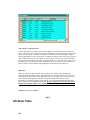
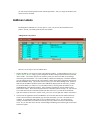
The Exclude feature allows you to exclude a particular DX spot from being treated as needed. To
invoke this feature, you click on an entry in the DX spot tab of the DX Info window and right
click your mouse. Choose Exclude and this will mark this callsign, band, and mode so that future
spots that match this criteria will no longer be treated as needed.
To view the entries that are on your Exclude, right click you mouse in the DX Info window and
choose View Excludes. This will show you the list of all entries that are currently on your
Exclude list. You can periodically delete entries that are no longer needed on the Exclude List.
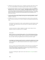
In the Internet and VHF packet windows, when a DX spot arrives that is on your Exclude List, the
entry will be marked with the letter “E on a black background in the status column of the VHF
packet or Internet window. Entries that appear with the “E will not be loaded into your DX Info
window.
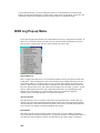
Auto Lock of Scrolling
A feature is available that automatically locks updates and scrolling in the VHF packet, Internet, and DX Spot
windows.
During periods of high volume DX spotting, it can become difficult to click on a particular DX
spot to QSY the radio and so forth because entries scroll so fast. Sometimes when you click, you
actually click the next spot because the one you intended to click has scrolled.
When autolock scrolling is enabled by using the main menu VIEW | Use Autoblock Updates is
enabled, DXbase will recognize when your mouse cursor enters any of these three windows. It
will automatically block further updates for a period of three seconds. After three seconds have
elapsed, if there has been no mouse movement in these windows, the scroll locking is
automatically removed and the windows scroll as normal.
The option is toggled on/off simply by clicking the VIEW | Use Autoblock Updates. A check
mark will appear to the left of the menu item when it is enabled. The check will disappear when it
is disabled.
During the time while locking was enabled, some spots will be held in queue. These will be
displayed in the appropriate windows as soon as the next DX spot arrives. Therefore, with
5
Autoblock Updates enabled, there can be a lag in time before the windows show the spots that
were in this queue.
Generally, you will not need this feature enabled unless the packet activity is high.
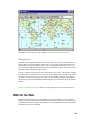
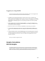
Internet Interface
Internet Packet Overview
DXbase provides a fully functional interface to the Internet Telnet sessions. This section describes
some details that are specific to the Internet functionality. Most functions described for VHF
packet are identical to the Internet module and unless mentioned otherwise in this section, those
features are not repeated separately. You should refer to the descriptions under the VHF Packet
section.
DXbase allows for a connection to the VHF packet and also to the Internet Telnet Packet
simultaneously. There is a separate set of user options for Internet where you can assign unique
sound files etc. that apply to the Internet packet. There is a completely separate window for
Internet packet.
DXbase implements the Internet functionality using standard Windows 95/98/NT architecture.
This means that DXbase uses the standard Windows Host file to locate the IP address for the
Internet site where a connection will be established. DXbase is shipped with a default HOST file.
DXbase does NOT automatically establish an Internet connection when you start DXbase. If you
intend to connect to the Internet Packet, you should first establish your Internet connection to your
Internet provider through normal means. Then, in DXbase you should select WINDOW/NEW
INTERNET. DXbase will then automatically examine your Internet User Options to identify the
Host IP that will be used to establish the connection to the Internet DX Telnet site. Upon
successfully establishing the connection, the Internet Packet window will be automatically
displayed on your screen. If a connection fails, an error message will usually be displayed and the
internet window will also be displayed. You should close the internet window by the clicking the
X in the upper right corner of the Internet Window and repeat this process after correcting the
problem. Sometimes a connection may fail due to a timeout condition when your internet
provider fails to respond to a connect request. This is a normal occurrence when internet systems
are very busy and therefore you should simply keep trying. Sometimes the DX cluster IP that you
are trying to connect with is busy and is unable to make the connection quickly thus resulting in a
timeout. Try switching the IP Host in Internet User Options to try a different cluster.
In addition to displaying DX spots and talk messages in the Internet Packet window, if user
options are set, DX spots and Talk Messages that may be received will be populated into the DX
Info window along with those that are received over the VHF packet link. The source of an entry
in the Packet Info window is marked as I or V.
6
Remember to log off of your Internet connection before terminating DXbase.
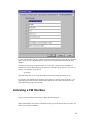
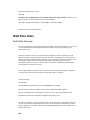
Making an Internet Connection
Prior to trying to connect to an Internet Cluster Telnet site, you must first establish a connection to
your ISP using your normal procedure for making this connection. This is performed outside of
DXbase. This establishes your connectivity to the Internet. Next, you select Window/New
Internet from the DXbase main menu.
This will cause DXbase to attempt to make a connection to the Internet Cluster site selected in
Internet User Options. During this process, DXbase will use the parameters from user options to
log on to the cluster site. If successful, you will see an Internet Packet Window automatically
appear on your screen and login information will be displayed. This process can require upwards
of thirty seconds depending upon how busy the internet might be at the time you try to connect.
If DXbase is unable to make the connection, you may notice that nothing appears to be happening
and you may even be fooled into believing that DXbase is locked up. This will generally not be
the case. What you are observing is that DXbase is making multiple attempts to try and establish
the connection or it is waiting for a response from the Internet cluster site. During this process,
DXbase does not respond to key strokes or mouse clicks. After approximately one minute, if a
connection is not established, DXbase will abort and a message will be displayed on your screen
advising of the failure. The Internet Packet window will be displayed, but no connection will have
been made. Following this, you should close the internet window that appears by clicking the X,
open internet user options and select a different IP HOST, and try the procedure again, this time
with a different site.
Establishing a connection requires that all the parts be working. That is, the DXbase software
must be working, the connection to the internet must be established, and the internet cluster site
must be operational. In some cases, you will find that the internet is very busy and thus
bottlenecks can occur which causes DXbase to timeout before a connection is achieved. Or, the
internet site you are trying to use is down for whatever reason.
Keep Alive Feature
Internet Service Providers and telnet DX Cluster sites sometimes implement an inactivity switch. Those who
are connected but do not perform any activity for a certain period of time may be automatically disconnected by
either the ISP or by the DX Cluster.
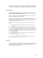
DXbase provides a feature called “Keep Alive which will automatically send a c/r to the Internet DX Cluster that
you are connected to. This generally satisfies the requirements of the ISP and DX Cluster so that both know
that you are still active. It is not foolproof and we have no guarantee that either might implement different
timeout software that defeats this feature in DXbase; however, it is effective for most connections and software
in use today.
7
The interval at which the Keep Alive sends a command is controlled by User Options for the Internet tab.
Internet-Host File Usage
DXbase adheres to the industry standard for establishing an internet connection via a telnet
session. As such, the Windows HOST file is used to obtain the IP address that is to be used for a
connection.
Host File placement during installation
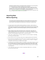
At the time you installed DXbase, a check of your Windows directory was made to determine if
you had an existing Hosts file. NOTE: there is no file extension, just the base filename.
If a file by this name was not found, then DXbase installed a its Hosts file that contains most of
the currently operational IP addresses that provide Internet Cluster service. If a Hosts file was
already resident in your Windows directory for Win95/98/ME or Winsystem32/drivers/etc for
WinNT/2000/XP, DXbase renamed your existing Hosts file to Hosts/dxb24/bak, where dxb24 is
the version of DXbase that performed this action. A copy of the DXbase Hosts file was also
placed in your DXbase folder in case you need it for some use in the future. If the IP Host list box
in the User Options Internet tab is empty or does not contain any valid entries for DX Clusters,
then chances are that your system did not allow DXbase to rename your old Hosts file, or some
other application has replaced our Hosts file. In either case, you will need to either copy the Hosts
file from your DXbase folder into the appropriate folder on your system based on operating
system replacing the one that is there, or, you will need to copy the data from the DXbase Hosts
file and paste it into your Hosts file.
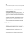
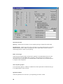
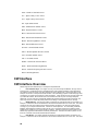
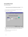
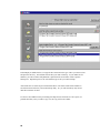
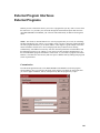
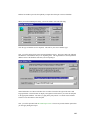
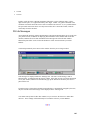
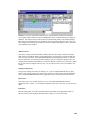
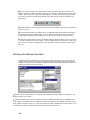
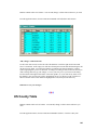
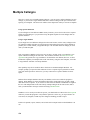
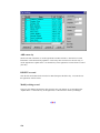
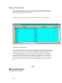
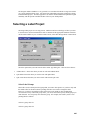
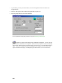
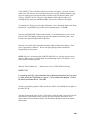
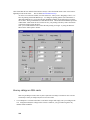
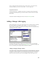
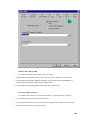
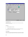
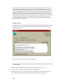
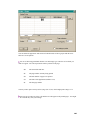
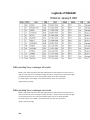
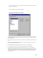
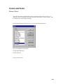
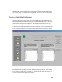
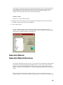
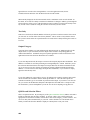
Editing a Host File
From time to time, you may discover that new IP addresses become available or old ones become
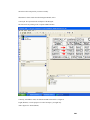
disconnected. You can edit your Hosts file from within DXbase. Select from the main menu
FILE/Modify Host File.
8
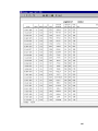
The current contents of your Hosts file will be displayed.
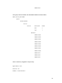
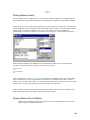
When making entries into the hosts file, you MUST follow certain predefined rules for the format
of what is entered.
1.
When entering an IP address the entry will be in four sections such as 24.17.21.123
2.
You can follow this with a # symbol and place a short comment after it.
3.
If the IP you want to enter requires a specific port, you should follow the entry described in item 1
above with a colon and the port number. No spaces before the colon or after the colon.
4.
Some clusters do not use an IP address but instead use the URL description. These entries follow the
same rules as above. You can look at the existing entries if you are unsure about the format.
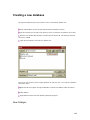
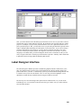
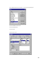
Add a new entry
Click the “New (Insert) button and enter the new IP on the empty line that is displayed. Click
anywhere within the window to change out of edit mode.
Delete an existing entry
Click the entry you wish to delete and then click the delete button.
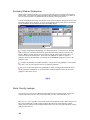
Change an existing entry
9
Double click the entry you wish to change. The line will be placed in edit mode and you can over
type your changes. Click anywhere in the window to change out of edit mode. Click OK to save
your changes, or click cancel to abort your changes.
Note: When modifying the hosts file, the hosts file that is being edited is the one that is located in
your Windows folders and NOT the copy that was placed in your DXbase folder. So, if you
routinely backup DXbase related files, you will want to backup the hosts file from your
appropriate Windows folder. The copy that was placed in your DXbase folder was only put there
in case you needed to refer to it when editing an existing hosts file.
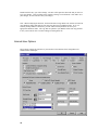
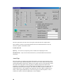
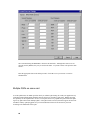
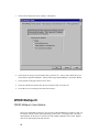
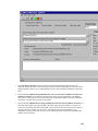
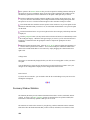
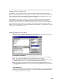
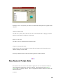
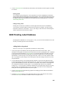
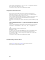
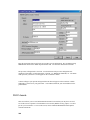
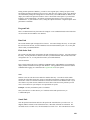
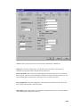
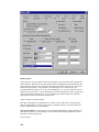
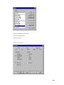
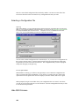
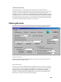
Internet-User Options
These options control the operation of your interface to the Internet Cluster using Microsoft
standard Telnet techniques.
10
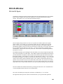
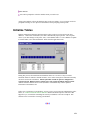
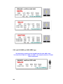
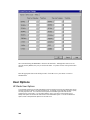
DXinfo Options
As DX spots are received, DXbase writes the information to the VHF Packet and/or the Internet
Packet windows. DXbase also provides another window called DXinfo under the DX Spots tab
where only DX spots are stored. This option controls when DXbase will place an entry into the
DXinfo DX spots window. This provides a convenient place to see only DX spots. We
recommend that this option be set to “Save Needed DX spots. Or, if you do not plan to use this
feature, choose “Do Not Use. Saving all DX spots can cause this table to become very large and
result in performance slowing down. You can eliminate performance impacts by frequently
emptying the contents of the DX Info DX Spots tab.
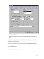
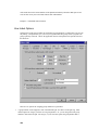
Connect Interface at program startup
This option tells DXbase to automatically try to make a telnet connection to your DX Cluster
when you start DXbase. For this option to work, you MUST first have your connection to the
internet established before you start DXbase.
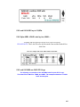
Auto Screen Statistics - As DX spots are received in the Internet Packet window, DXbase can
automatically update your screen display to reflect statistics and manager information. Place a
check here to turn this option on.
Screen Updates
This option tells DXbase when to update your screen based on incoming DX spots. You can
choose to have no updates. Or, you can choose to have the screen updated each time a DX spot
arrives in the VHF packet window. Lastly, you can choose to have your screen updated only
when a DX spot is loaded into the DX Info window. We recommend the last entry ( DX Info )
because your screen will only be updated based on DX spots that you need. Screen updates refers
to updates to the Summary window, QSL info window, previous QSO toolbar, etc…
Disable Sound on Exit - Place a check here to have DXbase automatically turn all sound off upon
exiting the program. By doing this, the next time you start DXbase, all sound will be disabled
until you turn it back on by clicking the speaker ICON located on the DXbase status bar.
Max Packet Lines - Enter the number of lines that are allowed to accumulate before DXbase
begins overwriting the oldest entries. Recommended value is between 1 and 2 thousand. The
higher this number, the more memory that DXbase will require.
DX Spot Key - This is the unique set of characters which represents a DX spot. The default is DX
de.
Sound choices - The type of sounds that are used are based on the sound files that have been
selected under the User Options directory tab. There is a choice for one of the following:
1.
YL sounds
2.
OM sounds
3.
CW sounds
Bell Sound - Select the sound file that DXbase will use whenever it received the “Bell character
from the Internet host.
11
Needed Sound - Select the sound file that DXbase will use to announce that you need this DX
spot.
IP Host - Select the IP connection that DXbase should use whenever you attempt to establish a
connection to an Internet Cluster. You should see a list of choices available in this box. If you do
not see any, or if you only see a few, then the DXbase Hosts file has been replaced by some other
Hosts file. You will need to correct this condition before you can proceed. Once your system is
verified to be using the DXbase Hosts file, you can use the “Modify Hosts option to add, change,
or delete entries in your Windows host file.
Announce DX spots in voice - Choose this option if you want DXbase to announce the callsign
and frequency of each incoming DX spot phonetically using your Windows sound system. Select
Only DX Spots Needed to announce the callsign of a DX Spot only if it is needed based on Alert
Options. Select All DX Spots to announce the callsign of all DX spots. Select Never to disable
this feature.
Audible Mail - Check this box if you want DXbase to automatically notify you when new mail is
received over the Internet Packet connection.
Audible Call - Check this box if you want DXbase to play the “Needed sound whenever it detects
the callsign entered under User Options Alerts in the call alert field.
Audible DX Alerts - Check this box if you want DXbase to play the “Needed sound whenever it
detects a DX spot that you need based on the parameters set in user options Alerts.
Audible Bell - Check this box if you want DXbase to play the “Bell sound file whenever it detects
the bell character from the Internet Packet connection.
The following parameters control the automated connection process to your Internet Cluster.
Login Prompt - This is the series of characters received when the host wants you to enter your
login. The default is login:
User Login - This is the login that DXbase will send in response to the Login Prompt. This is
your callsign. Only callsigns that have been registered can be used. If you enter a callsign that
has not been registered, the entry will be ignored and will not be accepted.
Password Prompt - This is the series of characters received when the host wants you to enter
your password. The default is Password:
User Password - This is the password that DXbase will send in response to a Password prompt.
Usually this is your first name.
Host Prompt - This is the character received when the host is ready to receive a connect request.
The default is the greater than symbol>
User Connect - This is the connect command that DXbase will automatically send when it
receives the Host Prompt. Usually this is DXC for DX Cluster.
12
NOTE: Novell installations
If your installation includes Novell's IP/IPX gateway that renames the WSOCK32.DLL to
WSOCK32.N01 you may encounter an ERROR STARTING PROGRAM. The DXB2006.EXE
file is linked to a missing export WSOCK32.DLL:1140
Rename the WSOCK32.N01 to WSOCK32.DLL
If your system is using a real TCP/IP address, or DHCP, or obtaining the IP address from an IP
server, there is no problem.
Internet- Proxy Server Usage
DXbase will function in an environment where the proxy server is configured correctly. Some issues to take into
account are:
Each computer will need to be set up with a different internal TCP/IP address and pointed out to
the proxy as the default gateway unless you are using DHCP.
Configure your computer’s TCP/IP properties.
Consult your operating system documentation and reference material for installing Proxy Servers
for further information on configuring your system.
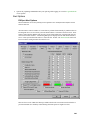
Packet Interface
VHF Packet Overview
DXbase provides a fully integrated interface to the VHF PacketCluster network. Through this
interface, you can perform all of the functions that the system offers. User options in DXbase
control the automated processing which can be performed by DXbase when incoming packet
messages are received. Alert user options control the manner in which DXbase will automatically
check incoming DX spots to determine whether or not it is a new one for you. Through these
options you can also specify the type of sounds that DXbase should play when an incoming
message is received and when DXbase determines that a DX spot is a new one. PacketCluster is a
trademark of Pavillion Software.
13
If the data content of a line exceeds the horizontal width of the window size, DXbase will
automatically show the full line when you position your cursor over the line.
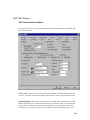
Serial Port Configuration:
You must configure DXbase to operate with your computer’s serial port. These TNC options
define the serial port parameters such as baudrate, parity, etc. that DXbase should use to
communicate with your TNC.
DX Alert Configuration:
You must configure DXbase DX Alert Parameters in order for the automatic lookup process to
work the way you want. These options also control the audible sounds that are associated with
packet events.
Checking a DX spot
If you click a DX spot in the VHF Packet Window, the entry will be highlighted and DXbase will
perform two functions. If you have set the user option to Display Screen Statistics, DXbase will
automatically update all windows on your screen with the current statistics for the entry you have
selected. Additionally, the callsign, frequency, and if applicable RTTY mode will be temporarily
stored so that these values can be populated into your QSO Log if you click the Log Spot ICON.
A new DX spot will automatically overwrite the last values that were temporarily stored.
QSY HF Radio
If you have an HF radio interface active in DXbase, your HF radio will be automatically changed
to the frequency and mode of the DX spot when you click in the TYPE column of a DX spot or
SH/DX entry..
14
NOTE: Do NOT set the TNC option to force all characters to upper case. If you do, DXbase will
not recognize any DX spots.
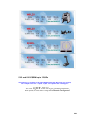
ICONS used for Incoming Packet Messages
DXbase identifies incoming PacketCluster messages in four ways:
Red X identifies DX spots that are not needed.
Green check identifies DX spots which are needed..
Yellow with horizontal lines is an entry which contains the phrase “mail in it..
Packet Pop Up Menu
You can click the right mouse button anywhere in the Packet window to display the Packet popup
menu.
1. Log Current Entry causes DXbase to log the DX spot or SH/DX entry that was clicked and is
now current in the Packet window.
2. Reset HF Frequency causes the HF radio to be reset to whatever frequency and mode was last
used prior to the current settings.
3. Empty All entries erases all entries in the Packet window.
4. Delete Current Record erases the current packet entry.
5. Show DX issues the standard SH/DX command
6. Directory issues the standard DIR command
7. Read New Mail issues the standard read command
8. Read Message issues the standard read command but additionally extracts the message number
from the currently selected line. Example, right click on a line that contains a message such as
15
would be the case after the results of a Directory command are displayed. Then select the Read
Message command.
9. More commands displays a dialog box where you can select user defined packet commands.
You can also click the CMDS button on the Packet Window to activate the More Commands
window.
10. Connect to Host issues the command entered in user options for.
11. Disconnect Host issues the standard Bye command.
Conserving Memory
DXbase automatically limits the number of messages that are contained in the VHF PacketCluster
window to the value entered in user options for Max Packet Lines. If you have limited memory,
you should make this entry as low as possible and still preserve the number of packet lines that are
reasonable to you. Normally a setting of 500 is adequate.
Upload Clipboard
Uploading ASCII text from the clipboard to your local packet network can be accomplished with
the following procedure:
Click in the outgoing packet transmit window and send the command to your packet network to
send mail. Usually this is ‘S’ for send or ‘S/P’ to send private.
When prompted by your network, send the subject.
With the packet view or Internet view in focus, click File on the application menu and choose
Upload Clipboard.
You will be prompted to insure that you have sent the above mentioned commands. This is
important because once you begin the upload process, there is no method for stopping the upload.
Answer Yes if you are ready to send, or answer No if you have not already executed the
commands to send mail.
When the upload is finished, a dialog box will be displayed advising that the process is complete.
When you click OK, a control Z will be sent to terminate the upload.
NOTE:
16
During an upload, all outgoing packet commands will be disabled until the upload is completed.
We recommend temporarily turning ECHO off in your TNC before uploading a file and then
turning ECHO back on after the file transfer is complete. This will overcome a limitation in the
ability to properly deal with a limited buffer in the TNC and the serial communications logic in
DXbase. This limitation is described below:
The file transfer process does not immediately display the outgoing lines of text; however you will
be able to see the status indicators on your TNC as evidence that outgoing data is being
transferred. Once the TNC buffer is full, you will see a burst of incoming lines of text from the
file you are transferring. This is the result of the TNC echoing back the text. There is a limitation
in the interface between the TNC and DXbase which only allows for approximately 25 lines of
text to be echoed. If your file is larger than this, you will see some distorted lines of text after the
first 25 lines. Please do not be alarmed. This is only the TNC echo. The actual data transferred is
intact and transferred accurately. If you read the file back from the packet network, you will see
that the data transfer took place without problem. This limitation will be addressed in a future
release.
Upload Files
Uploading ASCII text files to your local packet network can be accomplished with the following
procedure:
Click in the packet transmit window and send the command to your packet network to send mail.
Usually this is ‘S’ for send or ‘S/P’ to send private.
When prompted by your network, send the subject.
With the packet view in focus, click File on the application menu and choose Upload File.
You will be prompted to insure that you have sent the above mentioned commands. This is
important because once you select a file for upload, there is no method for stopping the upload.
Answer Yes if you are ready to send a file, or answer No if you have not already executed the
commands to send mail.
Select the file to be uploaded. Valid files are ASCII text files and this is the default file extension
that will appear in the File Open dialog box.
17
After selecting a file, click open to start the upload. When the upload is finished, a dialog box will
be displayed advising that the process is complete. When you click OK, a control Z will be sent to
terminate the upload.
NOTE:
During a file upload, all outgoing packet commands will be disabled until the upload is completed.
We recommend temporarily turning ECHO off in your TNC before uploading a file and then
turning ECHO back on after the file transfer is complete. This will overcome a limitation in the
ability to properly deal with a limited buffer in the TNC and the serial communications logic in
DXbase. This limitation is described below:
The file transfer process does not immediately display the outgoing lines of text; however you will
be able to see the status indicators on your TNC as evidence that outgoing data is being
transferred. Once the TNC buffer is full, you will see a burst of incoming lines of text from the
file you are transferring. This is the result of the TNC echoing back the text. There is a limitation
in the interface between the TNC and DXbase which only allows for approximately 25 lines of
text to be echoed. If your file is larger than this, you will see some distorted lines of text after the
first 25 lines. Please do not be alarmed. This is only the TNC echo. The actual data transferred is
intact and transferred accurately. If you read the file back from the packet network, you will see
that the data transfer took place without problem. This limitation will be addressed in a future
release.
Processing Incoming DX Spots
Determining the Mode of a DX spot
In determining the mode of the DX spot, DXbase uses two factors. If the comments section of the
DX spot contains the phrase RTTY or FSK, then the DX spot is considered to be the RTTY mode.
Otherwise, the Band Plan settings specified in “Band Plan user options will be used to determine
the mode.
Previous QSOs with a DX spot
When a DX spot is received, you can click the “previous QSO ICON on the main toolbar and
DXbase will display all previous QSOs with the callsign of the last DX spot received. Note that if
you click on a QSO record in the log after a DX spot, the callsign from the log will supersede the
DX spot when you activate the Previous QSO feature.
SH/DX command
DXbase will treat the results of a SH/DX command as if they were DX spots. You may click on
an entry and DXbase will process the entry in exactly the same manner as if it were a DX spot.
There are no audible sounds associated with the results of a SH/DX command. The ICON
indicator will remain as the default ICON since these are not actual DX spots.
18
Evaluating QSX, UP, and DOWN
If an incoming DX alert contains QSX in the comment section, DXbase will evaluate the QSX
information as follows:
If a valid frequency is detected, DXbase will attempt to use the frequency to set your VFOb,
assuming your HF radio is capable of handling split operation through the serial port interface.
The format of the comment MUST be QSX 14195.0. In this example, there is one space
following QSX. QSX is in upper case. The frequency contains all digits and at least one decimal
place. If this format is not present, the QSX information may be ignored.
If the comment section contains the phrase QSX UP or QSX DOWN, DXbase will add or subtract
5 Khz from the frequency in VFOa and assign the result into VFOb, assuming your HF radio is
capable of handling split operation through the serial port interface.
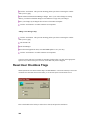
Send a Stored Command
DXbase provides several ways to automatically send a predefined command. In the VHF or
Internet windows, click the right mouse button for a menu of options:
The “Read Message choice will issue a “Read command and use the message number of the line
that you clicked when you activated the right mouse menu.
The “Read Mail choice will issue a Read command to automatically retrieve any unread mail.
The “Connect Host will issue a connect command using the parameters that were entered in user
options.
The “Disconnect Host will issue the “Bye command.
The “Show DX and “Directory choices will issue these commands.
The “More Commands displays a dialog where you can choose from your previously stored list of
commands. You can also access “More Commands by clicking the CMDS button located in the
upper left corner of the VHF and Internet Packet Windows. To select a command and send it as
listed, highlight the command and click OK.
19
If you wish to select a command and also modify it or add to it before it is sent, click the
command you want to change and then click the “Substitute button. This will cause the command
to appear in the Command Substitution box. Overtype with your changes and click the Transmit
button to send your modified version. If you place a check in the “Erase on Transmit box, the
entry in the Command Substitution box will be automatically erased when you transmit the
command.
Send a typed command
There are many ways to send a packet command in DXbase.
The Transmit window contains a tab for VHF packet and another for Internet. Choose the
appropriate tab when typing into this window. The tab that is selected will control whether the
entries are sent to the VHF packet host or to the Internet host. To transmit the line, press the enter
key. If you press a control character, the line will be automatically sent including the control
character that was pressed. Remember that if you intend to send some character out, your cursor
must be positioned in this window. If your cursor is focused on some other window the characters
you type will not be sent.
There are several ways to send outgoing PacketCluster commands.
1.
Select a stored command from the right mouse menu inside the appropriate Packet window.
20
2.
Click inside the packet transmit window and type the desired outgoing command or message. Press
the keyboard ENTER key to send the displayed text. Text that you type will automatically scroll to
the left if you exceed the width of the edit box.
3.
To send a control character to your TNC, click inside the packet transmit window and type the
control character. Any text already present will be automatically erased and the control character will
be sent to the TNC.
4.
To send an ESC character to your TNC, DXbase has implemented a substitute character called the
tilda ( ~ ). This is necessary because Windows uses the ESC character for Windows. So, if you need
to send an escape character ( ESC ) use the ~ ( TILDA ) character instead.
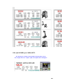
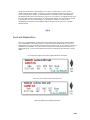
Send a DX Spot
A DX spot can be sent by clicking the “Send DX Spot icon located on the VHF Packet toolbar or
the Internet toolbar. The last callsign that was current in your log will be pre-populated in the
callsign field of the DX Spot dialog box.
To send a DX Spot, click the DX Spot button:
The first button on each toolbar will result in the Send DX Spot dialog being displayed. Note that
there is a separate toolbar for VHF Packet and Internet Packet.
Callsign
The Callsign field will be auto populated with the current callsign from your log.
21
VFOa
If you have an HF radio interfaced with DXbase, VFOa will be retrieved from the radio. If no HF
radio is connected, VFOa will be populated from the frequency field of your QSO log.
VFOb
VFOb will only be populated if your HF transceiver is in split mode and if identification of this is
supported in your radio’s RS232 interface. Some radios do not provide this functionality.
Use QSO Log to determine digital mode comment
Many of the newer digital modes cannot be determined by the mode setting of an HF radio. Often
times the HF radio may be set to RTTY or USB even though the actual mode used might be
PSK31 or BPSK, etc. For this reason, it may be more accurate to let DXbase use the QSO mode
from your log. If the mode of the QSO is one of the digital modes, it will be formatted into the
outgoing packet DX spot. If this option is not checked, DXbase will use the mode setting from the
HF radio.
Comment
If the mode is digital, it will be populated here. Additionally, if the HF radio is in split mode as
described above, the QSX frequency will be populated here. You can add additional comments by
typing them here. Or, if you want to erase anything that DXbase pre-populated, just delete it.
Send
Click the Send button to transmit the DX spot. DXbase will automatically format the outgoing
command.
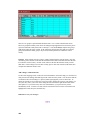
Create Stored Commands
Frequently used packet commands can be created and stored so they are available in the “More
Commands window. You can have as many stored commands as you want. You can edit or
delete commands in the command file as often as you want. DXbase uses the same window that is
used to send commands so that you can add, change, or delete entries in the same window.
Click the CMDS button located in the upper left corner of the VHF or Internet Packet Window.
Or, use the right mouse click inside the VHF or Internet Windows and select the “More
Commands option.
Tooltips are active. Position your cursor over a button and a pop up window will describe the
purpose for the button. The first nine ( 9 ) commands listed map directly to the nine toolbar
buttons available on the Packet Commands Toolbar. You can reorder your entries by highlighting
22
a command and then use the up and down arrow ICONs to move the command up or down in the
list.
Input Rules
1.
Maximum number of characters per line is 70.
2.
Control characters are not permitted. Only alpha/numeric.
3.
Blank lines located between lines are NOT permitted.
Adding New Commands
Click the “New ( Insert ) button. It is located to the left of the button with an X on it. Enter the
command in the blank line that is opened at the end of the list of commands. When finished, click
anywhere inside the list of commands to change out of edit mode.
Delete existing packet commands
Click the command that you want to delete. It will become highlighted. Click the “Delete button.
This is the button with the red X on it.
Change existing command
Double click the command that you want to change. The line will be put into edit mode and you
can overtype with your changes. Click anywhere inside the commands window to change out of
edit mode.
Reposition a command
23
Click the command that you want moved, and then click the Up or Down arrow to move the entry
to another relative position in the command list.
Save Changes
If you have made any changes to your list of commands, you MUST click the Save Changes
button for the changes to become permanent. If you fail to do this, any changes you might have
made will be erased when you close the window.
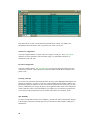
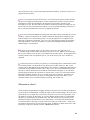
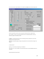
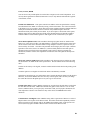
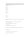
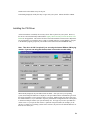
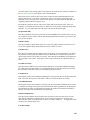
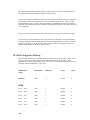
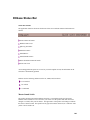
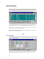
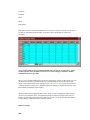
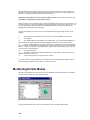
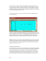
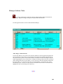
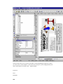
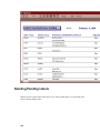
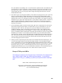
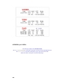
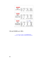
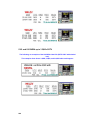
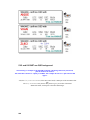
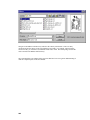
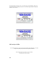
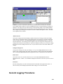
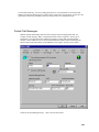
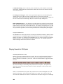
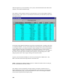
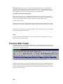
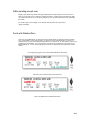
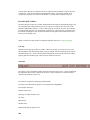
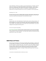
Packet Command Toolbar
There are two command toolbars available. One is for Internet Packet and the other is for VHF
packet. These toolbars provide nine buttons each. Each button represents a packet command that
will be sent when the button is clicked. The command that is associated with each button will be
displayed in a pop up tooltip when your cursor is positioned over the button.
The toolbar for sending internet commands can be identified by the blue color of each button. The
VHF toolbar uses a red color for each button. These toolbars can be hidden if they are not used by
selecting the customize option under the main menu View item.
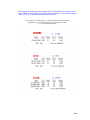
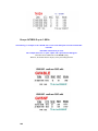
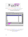
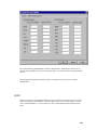
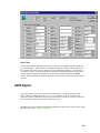
Commands for each button are obtained automatically from the first nine commands listed in the
Stored Command module. There is a separate Stored Commands module for Internet and packet.
So you can have different commands assigned to the buttons on each packet command toolbar.
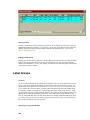
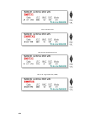
24
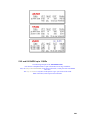
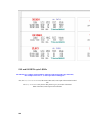
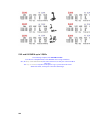
In the above window, the commands would map as follows:
C K4KG
button 1 on toolbar
SH/DX
button 2 on toolbar
SH/DX/10
button 3 on toolbar
SH/US
button 4 on toolbar
SH/CON
button 5 on toolbar
T K4KR
button 6 on toolbar
T K4KR are you there
button 7 on toolbar
SH/WWV
button 8 on toolbar
DIR
button 9 on toolbar
The remaining commands are not assigned to the toolbar. To change the order of commands just
use the Stored Commands module to reorder commands.
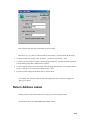
Deleting Packet Entries
Each VHF or Internet packet entry occupies 80 bytes of your computer’s memory. From time to
time you may wish to free up this memory by erasing all entries from the VHF or Internet packet
window.
To erase all entries, from the Right mouse popup menu in the Packet window, select Empty All
Entries.
User options for VHF and Internet specify the maximum number of lines that are allowed in each
packet window. When this threshold is reached, DXbase will automatically begin deleting one
line at a time beginning with the oldest line first whenever the total number of lines in the packet
view has reached Max Packet Lines value from user options.
You can delete one packet line at a time by clicking the Row button on the far left and pressing the
delete key. When you click the row button, the entire record will be highlighted. This serves as
an indication that you can now press the delete key to remove the record.
NOTE: If you press the delete key after clicking inside a field, you will erase the contents of that
field but will not delete the record.
25
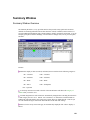
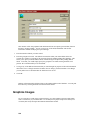
Processing IOTA data from DX Spots
As incoming DX Spots are received, DXbase can optionally extract IOTA information if it is contained in the
comments field of the DX spot. The operation of this automatic feature is controlled by the settings in the User
Options Alerts tab. In order to be detected, the IOTA information must be in one of the following formats:
1.
NA160
2.
NA-160
3.
NA 160
If IOTA information is detected, the HF IOTA statistics will be reflected in the Summary window
if you have the HF IOTA category selected. In addition, when logging a DX Spot, the IOTA field
of the QSO being logged will be automatically populated with the IOTA information obtained
from the DX spot.
If you have selected the option in the Alerts tab of user options to have IOTA alerts, DXbase will
process an incoming DX spot to determine if it contains a needed IOTA. If it is, then it will be
annotated in the packet windows as well as DX Info window as a needed IOTA. NOTE that if a
DX spot is needed as a new country, no IOTA checking is performed. IOTA checking is only
performed if the DX spot is not needed as a new country.
Notes:
In the “real world, DX Spots are not always sent accurately by the sender or originator of the DX
Spot. Sometimes the letter ‘O’ is used in place of the numeric zero and vice versa. For example
the IOTA “OC111 might have been typed using a numeric zero instead of the alpha O . In this
case, since the data itself is incorrect, DXbase would not recognize this as an IOTA.
Introduction
Welcome
Thank you for choosing DXbase for your logging operations. We sincerely appreciate your
confidence in our products and will strive to provide the best value money can buy.
DXbase is perhaps the most sophisticated logging software ever produced. In fact, it is more
complex in what it does than most other commercial software that you may have installed on your
computer (unless of course you are a developer or engineer enthusiast). But, despite the
complexity that goes on behind the scenes, we have tried to make DXbase very easy and intuitive
to use. Nevertheless, there is a learning curve which you will face before you will completely
understand all the subtle features and operations at your disposal. For most users, this will be
26
quite small, but for some, you may find certain operations confusing. To this end, we have a few
suggestions that may help.
Please (we mean this sincerely) take the time to review this help file and any readme files that
may have been shipped with this product. We have employed the assistance of nearly a dozen
individuals to prepare this information in the hope that it is presented as completely and
thoroughly as we can. We have made our best effort to insure that virtually everything you will
need or want to know is described in the help file. If you cannot find something, let us know so
that we can make the addition the next time we upgrade the software.
Please do not assume that DXbase does things like some other software (including our previous
products). Chances are that it does not. DXbase contains the absolute latest technology in the
software industry for 32 bit operating systems. It is also developed to be in compliance with
Microsoft Certification requirements. Very few, if any, other logging programs are designed to
these high standards. Once you use DXbase, you will no doubt recognize the difference that
DXbase brings to your operation.
We know you are probably going to be in a “hurry to get started. We appreciate your
enthusiasm and have tried to make “getting started as easy as we can. But there are a few things
that we just could not avoid. Be sure you set DXbase user options correctly. By taking the time to
carefully consider each user option that you set, you will be well on your way to trouble free
operation.
If some feature does not work for you, please try to avoid jumping to the conclusion that it must
be a software problem. We know this is only natural (we are guilty of this too). But, we can
sincerely tell you that DXbase has been thoroughly tested. We have a sophisticated automatic test
system that exercises DXbase 24 hours a day, 7 days a week. We also enlisted the help of many
beta testers. Unless mentioned in our readme file, when DXbase is shipped, we are sure that it
performs properly based on the experience of our beta testers. It may very well be that you have
identified an unknown problem. If so, we certainly want you to let us know. But chances are
better that you may have some user option, or configuration error that is the culprit. If you
encounter trouble, be sure to check the help file, the FAQ, and our Web site.
Will you do us a favor?
The development and production of logging software is extremely time consuming and expensive.
If you are like us, Amateur Radio is a hobby for which we have a limited budget. We can’t always
go buy all the toys we might want. In an effort to keep the cost to you as low as possible, we do
not spend lots of money on advertising. If you enjoy DXbase and agree that it is of substantial
benefit to you, please help us to spread the word. Tell your friends, voice your opinion on the
Internet news groups, and mention us to your club members. Your help in this regard benefits
everyone concerned. Obviously, we make a little more money (we surely need it … hihi), but it
also makes it much easier for us to keep the price down. In addition, it makes others aware of the
benefits they might enjoy with this software. Thank you in advance.
27
Quick Start for Experts
This information is intended for the experienced user of Windows and a user who is familiar with
the operation of previous versions of DXbase. Even if you are an expert user, there are a large
number of features contained in DXbase for Windows that are new or work differently. We
encourage even the experts to look through the help topics and become familiar with the new ways
in which this product operates.
1.
2.
Windows like any other Microsoft compliant product. Run setup.exe.
Execute DXbase.
3.
Choose Tools/Options/User Options and set all of the user options for every tab. Save
your entries.
4.
Drag the individual windows around and resize to suit your preferences for screen
display.
5.
Packet commands can be typed in the Packet Transmit Window. With your cursor inside
the packet transmit window, press the Enter key to actually send the command. Click the right
mouse button inside the VHF or Internet Packet View windows and choose Other commands to
send a user defined command or choose one of the other choices on the pop up menu. The CMDS
header button will also activate the “More Commands module.
6.
Click in any QSO record and the statistics in every window will be automatically
updated.
7.
Click on any DX spot in the Message Column and the statistics in every window will be
automatically updated if you have the user option “Display Screen Statistics set. There are
separate options available for VHF Packet and Internet Packet. The default QSO sort index
is DATE and TIME.
9.
Click on any column header to sort your QSO log by that column.
10.
Click in the QSY column of the VHF Packet or Internet views for a DX spot or SH/DX
list and your HF radio will automatically QSY to that frequency if one is used. Screen statistics
will also be updated.
11.
To log the latest DX spot, click on the spot and then click Log DX Spot ICON. The log
will be populated with all the necessary information. Save the new QSO record by choosing
Record/Update or simply click on some other record in the log to automatically save your new
record and make the record you clicked current.
12.
To add notes, fill in the callsign notes box in the Summary Window. The callsign of the
QSO should already be displayed in the callsign field of the Summary Window. Choose
Record/Update or the save Icon to save the notes.
13.
Click the previous QSOs ICON to see past QSOs with a callsign, zone, prefix, etc. Or
click on the matrix in the Summary Window for the band/mode combination you want to see.
14.
28
Click the QSO Label ICON to save QSO label data for the current QSO record.
15.
Customize the appearance of the QSO Log, VHF Packet, and Internet windows by setting
styles and properties .
16.
Open the TOOLS/OPTIONS/Personal Data module. Enter your personal information,
especially your callsign, since this is what DXbase will use when preparing reports and labels etc.
17.
Use one of the two Import Utility programs to import data from a previous version of
DXbase or some other logging software. Please be aware that there are two different import
utilities. DXB Import is for anyone importing data from a past version of DXbase for Windows.
The other utility is called plain Import and is for all other imports including ADIF.
18.
When you start DXbase, it will prompt you for the name of your database. Unless you
have already changed your database, the default will be yourcall.mdb located in your DXbase
directory. This should be the default displayed in the box when prompted. If during the original
installation, DXbase was not able to create a database using yourcall.mdb, then a database file
called default.mdb would have been placed in your DXbase directory. You should rename this to
yourcall.mdb before you use it.
19.
When closing DXbase, never close Windows without first closing DXbase and allowing
DXbase sufficient time to completely close itself down. DXbase may write data to the database
when closing down and it must be allowed to complete this process.
Quick Start for New Users
We’d like to welcome you to the DXbase family of customers. We want your experience to be as
pleasant as possible in as short a time period as we can. One point to keep in the back of your
mind is that DXbase is very powerful and flexible. For these reasons, there are many subtle
options that let you tune the software to operate in a manner that best meets your operating needs.
All of the topics are covered in fine detail elsewhere in this help file, but we have listed some of
the issues that a new user may find useful.
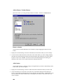
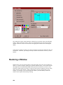
1.
When you first run DXbase, your screen display will contain the main DXbase window and inside
this there are many sub windows that are tiled one on top of the other. Using your mouse, you should
click on the title bar of a sub window, drag it to the part of the screen where you want it positioned,
and size it to the size you want. You repeat this for each of the sub windows. If there is a sub
window that you don’t care about seeing, do NOT X it out to close it. If you do this, the window will
reappear the next time you start the software. Instead, use the minimize button for that sub window
to hide it.
2.
Near the bottom of the default screen, you will see two large white boxes side by side. One is the
previous QSO toolbar, and the other is the transmit window. In the default screen, these are docked
(or locked) to the bottom of the screen. You can click on the two vertical bars in these two windows
to drag it to another part of the screen and lock it there by just dragging it to where you want it. You
will see it change shape when it is in position to be locked. For a better idea of how you might
organize your screen, take a look at the section in this help file called Navigating the Screen. There
you will see an example of what you might want to do.
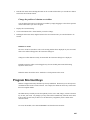
3.
There will be a horizontal bar of toolbar buttons. Actually there are many partitions of toolbars.
Chances are that these will be scrolled to the right out of view so that you cannot see all the toolbars.
You should click on each partition of the toolbar and holding your left mouse down, drag the toolbar
to the place on your screen where you want that toolbar to appear. As you drag a toolbar, the
29
remaining toolbar partitions will come into view automatically. If there are toolbars that you don’t
need, you can use the TOOLS/Customize menu option to close the particular toolbars that are not
desired.
4.
After you get your screen in order, the next task is to set your user options. These options are very
important for the operation of the software because this is where you tell the software about your
particular interests. Each option has been carefully considered and therefore, you should not
overlook anything. Use the help file for the User Option that you are setting and read about its
purpose. This way you will be sure that you have set the options in the best way to meet your needs.
All user options are located under the TOOLS/OPTIONS/User Options menu. There are three sets of
options of interest. These are the User Options, Personal Options, and Special Events. User options
will display a window with many tabs. Set all of the options under each tab. Personal Options is
where you set your callsign and address information. This information is used throughout the
software. Special Events is where you identify any special events that are coming up for which you
want DXbase to notify you when you start the software.
5.
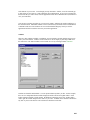
After completing the above, you are now ready to import any data that you might already have in
some other database. If your data is in one of the many formats supported by DXbase import logic,
you can now perform that operation. First, you should close DXbase. Then, using Windows
Explorer navigate to the DXbase for Microsoft Windows folder and you should find a file that uses
your callsign as the name with a file extension of .MDB. This is your database file. You should
make a copy of it and save it off to a safe place. This is just a precaution in case something goes
wrong when you are importing records. This way you can always get back to where you started. If
you are importing data from previous versions of DXbase, you should review the instructions in this
help file for the procedures to follow. If you are importing data from some other logging program
you should open the Import Help file which is located in the DXbase for Microsoft Windows
program group. If you are importing from DXbase for DOS v5, use the ADIF import option from the
Import utility. If you are importing past versions of DXbase for Windows, use DXB Import.
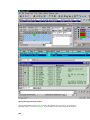
6.
Next, you will want to know how to log QSOs. It’s simple, just click in the callsign field of the last
empty record, type in the callsign and press the tab key. All fields will now be populated. Overtype
any you want to change and then click the save ICON (looks like a disk) to save the record. There
are lots of other ways to log QSOs directly from a packet spot, from an internet spot to name a few.
To learn all about these processes, you should review the documentation for those modules and the
section called Logging. Before logging, make certain you have reviewed the user options under the
log tab. You will see many choices for how DXbase treats date/time. Make sure you read about
these and set them accordingly. Pay particular attention to the Update Date/Time option.
7.
DXbase makes extensive use of the right mouse pop up menu feature of Windows. In each of the sub
windows, you may find that if you position your cursor anywhere in that sub window and click the
right mouse, you will see a pop up menu of choices.
Now, we recommend that you begin to explore the help file. DXbase is clearly the most powerful
and feature rich logging software on the market. Most features are intuitive and easy to recognize;
however, many are not so obvious and you’ll be missing out on these if you don’t take a look at
the help file and review all that the software has to offer. You can also gain some additional quick
tips by looking the Quick Start for Experts section.
30
Closing DXbase
Never shut down Windows without first closing DXbase.
When you close DXbase, the software will save all of its internal statistics data to the hard drive
before the screen is destroyed. You can recognize that this process is underway by observing the
progress bar on the lower left side of the DXbase status bar. DXbase uses intelligent logic so that
it will only perform this process when it is necessary.
Be careful that you do not interrupt this process by shutting windows down before this completes.
If you do, you may experience problems the next time you start the software. Symptoms may be
that DXbase reports that it cannot find “such and such in the numeric statistics table. If this
happens, refer to the Error Messages section of this help file.
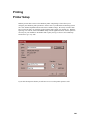
Printing DXbase Documentation
In order to conserve costs and keep the price of DXbase as low as possible, a printed manual is not
shipped with this product. Instead, the Microsoft Word document files are included in the DOCS
directory on the master CD.
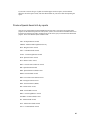
The following documentation is available:
1.
ADIF specfication .doc that describes the Amateur Data Interexchange Format for exchanging data
between logging programs. It is located in your DXbase folder.
2.
Label and List designer documentation. This information is extensive and is provided in both a .doc
and a .pdf format. To use the .pdf formatted file, you will need to open it with Adobe Acrobat that is
available on the internet. It contains detailed information about using the designer capabilities in
DXbase. Note: There is reference in these documents to some capabilities such as “bar coding that is
not implemented in DXbase. These are in the doc folder on your DXbase CD.
3.
All of the .doc files that make up the DXbase help files are in the doc folder of the DXbase CD. For
improved efficiency, we recommend you copy them to your hard drive before printing them.
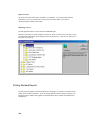
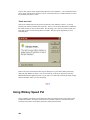
Using Microsoft Word or Wordpad, you can open the associated .DOC files contained on the CD
and print them. The result will be a complete manual complete with table of contents and index
pages. Simply insert the DXbase CD, open Windows Explorer, and navigate to the DOC
directory, double click the .DOC file. Alternatively, open Microsoft Word, and using
FILE/OPEN, open the .DOC file from the CD.
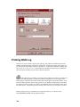
31
If you are using Office 97, be sure you have installed the latest patches from Microsoft. Without
this patch, you made see a large red X printed in places where screen images should appear.
NOTE: In some cases, the DXbase documentation may be available in translated form to other
languages. Since this information is subject to change, you should consult the DXbase Web Site
for information on availability, if any.
Before you ask, yes, we realize that it would be more convenient to have everything in one .doc
file; however, this is not feasible because the files are too large to be supported that way.
Therefore, we are forced to break the contents into separate .doc files.
Getting Information
For what it’s worth!
We have tried to insure that every topic associated with DXbase is included in the help file, tips at
startup, FAQ, or as a Knowledge Base article on our web site. Take advantage of all the sources at
your disposal.
Some users deprive themselves of valuable information by choosing to turn off “Tips at Startup, or
they would rather click around the screen trying to find something instead of using the help file.
Some will never go check the web site and still others will never look at the FAQ. You would be
amazed at some of the discussions we have had with long time customers who have used our
products for years and “never knew it would do this or that.
DXbase is a very powerful and feature rich software product. But, if you don’t know about all its
capabilities they won’t do you much good. Please don’t ignore the information that we provide.
It’s there to help you get the most out of DXbase, but you’ll never see it if you choose not to look.
Sources at your disposal
1. On line help system
2. Frequently Asked Questions (FAQ) in the on line help
3. Tips at Startup
4. DXbase Knowledge Base on the web at http://www.dxbase.com
5. DXbase Reflector ( signup information is on our web)
32
You can access the DXbase web site directly from within DXbase by choosing the HELP/DXbase
Web menu option.
Best Wishes
Scientific Solutions, Inc.
Our Policy
Third party Software and Hardware support in DXbase
We sometimes receive inquiries asking us questions like the following:
When will DXbase support such and such?
Why doesn’t DXbase support such and such?
Some other software supports such and such, why doesn’t DXbase?
Whenever we receive these kinds of inquiries, we usually contact the particular vendor in question
and request information about their product and any software interfaces that they include. For
those products that include a Microsoft compliant 32 bit .DLL, we are pleased to move forward
with an interface assuming there is sufficient customer demand. For those products that do not
provide a Microsoft compliant 32 bit .DLL, we tell the manufacturer that this is needed in order
for us to provide support. Some have accommodated this and developed the necessary .DLL, and
others have either ignored the request or out right refused.
DXbase is, in every sense of the phrase, “Leading edge technology. We have devoted thousands
of hours in development time to insure that we comply with industry standards. Why? The
simple answer is that this is the best guarantee that we have to insure that DXbase will continue to
perform as expected even though Windows operating systems may change; updated DLL files
shared by DXbase which are installed with other Windows products don’t cause harm to DXbase;
And, that DXbase causes no harm to other software. These are compelling reasons when you stop
to consider how rapidly the software technology is changing.
Our years of experience in the software development business have taught us the value of this
approach. It is a lesson well learned and for this reason, we will only endeavor to provide a
software interface to those products that are Microsoft Windows 95 and NT compliant for the 32
bit operating systems. In other words, even though it may be possible, we will not “hack in some
33
non standard code just to be able to interface with some other product at the risk of causing
DXbase to become “non standard.
We hope you will appreciate the importance of this issue and our reasons for adopting such a strict
policy in this matter. If you want DXbase support for some other product, tell the makers of that
product that they must provide a Microsoft compliant 32-bit .DLL or equivalent. In some cases,
we may require that they furnish a sample of their product for testing purposes.
Thanks,
DXbase Development Staff
Registration of DXbase
Registration Overview
DXbase incorporates a registration process that allows it to be distributed in trial or demo mode and after the
user obtains the registration key, the software automatically reverts to a fully functional registered version.
DXbase does NOT use any hardware locking in its registration approach. This allows the software and the
registration key to be used on a licensed user’s second machine. The same registration key that is used on one
machine can be used on a second machine.
ONLY those callsigns that are registered will be used within DXbase. If you attempt to use an operator callsign
that is not registered, you will encounter difficulties with DXbase.
When requesting a registration key for DXbase, the user will be required to submit the callsigns that are to be
used.
The following steps explain the overall process:
1.
User downloads the DXbase software from our web site, or they obtain the CDROM.
2.
User installs the DXbase software on their machine.
3.
DXbase can now be run in trial or demo mode. Trial mode will expire after 15 days and the software
will not run after that time has passed.
4.
User obtains the registration key after purchase. This registration key is a very small 1k file that
contains the user’s authorized callsigns and other information encoded into the registration key. The
registration key file will usually be provided by email to the user.
5.
User double clicks the registration key filename that is provided and Windows will automatically place
the registration information in the user’s registry. User also saves the registration file to a safe place such as a
floppy disk in case they need to reuse it after a hardware change.
6.
DXbase now becomes fully functional.
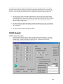
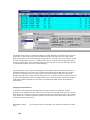
Registering Callsigns
34
When purchasing/registering DXbase, the user will be required to submit any callsigns that are going to be used
in DXbase. In order for a callsign to be registered, it must fit the requirements for ownership as follows:
1.
A callsign must be the official current callsign of the purchaser.
2.
A callsign must be a previous callsign officially issued to the purchaser.
3.
A callsign must belong to a second operator family member in the same household as the purchaser.
4.
A callsign must be a DX station and the purchaser is publicly authorized to serve as his QSL
manager.
Only the base callsign must be provided. For example, if the purchaser’s callsign is AA4LU, and the purchaser
also operated as AA4LU/HK0, FG/AA4LU/FS, and so forth, ONLY the base callsign of AA4LU is required. The
registration will automatically allow portable without the need to register each different portable callsign. Only
one registration key file is used for all callsigns. In other words, each registration key will allow multiple
callsigns.
If you once had a callsign, but you do not plan to enter QSOs for that old callsign into DXbase, then it does not
need to be included in the registration request.
Common Questions:
1.
What if I change callsigns? Answer: A new registration key must be obtained that includes your new
and old callsigns before the new callsign can be used in DXbase.
2.
What if I forgot one of my callsigns at the time I requested a registration? Answer: A new registration
key must be obtained that includes your callsigns before the left out callsign can be used in DXbase.
3.
I have used three callsigns, W1ABC, FK8ABC, and W1ABC/PY. What must be submitted for
registration? Answer: You must submit W1ABC and FK8ABC. The portable callsign for W1ABC/PY does not
need to be submitted and can be used in DXbase.
4.
I just purchased a laptop computer and I want to use DXbase on my laptop. Do I have to obtain a
new registration key? Answer: No. The registration key that was originally provided can be applied to your
laptop following the normal process for using a registration key.
5.
My hard drive crashed and I had to replace it. Do I have to obtain a new registration key? Answer:
No. The registration key that was originally provided can be applied after you reinstall DXbase on your new
hard drive.
6.
What happens if I lose my registration key? Answer: A replacement registration key will need to be
obtained if you do not have a saved copy of the registration key that was originally provided to you.
7.
How many callsigns can be included in one registration key? Answer: It depends on a number of
factors, but generally up to ten callsigns can be registered.
8.
I have several callsigns. Do I have to apply separate registration files for each callsign? Answer:
No. One registration file will cover all callsigns that were submitted for registration.
Using a Registration File
After submitting your callsigns for registration, a small 1k file will be returned to you. It can be
sent to you as an attachment to email or on a floppy disk (charges for mailing a disk would apply).
Registration File by Email
If the file is received by email, simply double click the filename attachment in the email and
Windows will ask you if you want to have the information placed in your computer’s registry.
Answer “yes and the registration process is complete. Alternatively, you could save the
35
attachment to a folder on your hard drive or to a floppy. If you do this, locate the file after it is
saved using Windows Explorer and double click it.
Registration File by Disk Mailing
If the registration file is received on floppy, open Windows Explorer and locate the file on the
floppy disk. Double click the filename and windows will ask you if you want the information
stored in your computer’s registry. Answer “yes and the process is complete.
Save the registration file in a safe place in case it becomes necessary to reinstall DXbase and reregister it.
Using Non Registered Version
The non registered or “trial/demo version of DXbase is offered for prospective users to give it a
test drive. DXbase is a very powerful software package and there are many subtle features that a
user will generally not know about unless they first take some time to review the on-line help
system located from the Help menu item on the main DXbase menu, or from the DXbase program
group on the Windows start menu.
If DXbase has not been registered, it will operate in “trial mode subject to the following
limitations:
1.
The trial period will only last 15 days from the time the software is installed.
2.
The only database that can be used in the trial version is a trial database that is provided. Any QSO
information that is saved into this database will not be available for use except in the trial version.
There are no capabilities to import this later. It is assumed that the “trial or demo version is only used
to evaluate features and is not to be used as any kind of a permanent log until after it is registered.
The trial database cannot be used in the registered version.
3.
A maximum of five QSOs can be added each time you run DXbase in trial mode.
4.
Various places in the software where a callsign is used will contain a default callsign.
5.
Technical support for questions that are addressed in the on-line help file contained in DXbase will
generally not be addressed by direct email. Trial users are welcome to subscribe to the DXbase
Reflector and pose questions there; however, it is expected that the internal on-line help file will be
used as first choice for answering questions.
36
New Callsigns
After using DXbase with a particular callsign, you may have occasion to change your callsign. Maybe you
obtained a new callsign through the US Vanity callsign process. Whatever the reason, the following process
will allow you to change your DXbase software for the new callsign.
NOTE: Prior to being able to use a new callsign in DXbase, the new callsign must be registered. You
can request a new registration from the DXbase web site.
Please note that you do not necessarily have to create a new database just because you change callsigns. You
may wish to continue to use the same database and change the Opr Call in user options to your new call. This
way, past QSOs and new QSOs will share the same database and the Opr Call field of the QSO log will
distinguish which callsign was used for that QSO.
This process assumes that you want to keep your existing QSO data and simply change the name of your
database:
1.
Open User Options General tab and put a check in the “Prompt for database name at startup.
2.
Close DXbase.
3.
Open Windows Explorer and navigate to your DXbase folder. If you used the default installation, it
will be located under Program Files/Scientific Solutions/DXbase xxxx where xxxx is the version number.
4.
Copy your existing .MDB file to a new file by clicking on the .mdb filename, use the menu Edit/Copy,
then do Edit Paste. On the right side of Windows Explorer, scroll to end of the file list and you will a file called
Copy of ….. whatever the filename of your database was. Edit the name to the new name that you want. Be
sure to include the .mdb file extension.
5.
Close Windows Explorer.
6.
Start DXbase and when asked for the Database name, use the selection arrow to select the new
database name that you want to use.
7.
You can now uncheck the user option from item 1 above.
If you want to start a new empty database for a new callsign, use the DXbase FILE/New Database option to
create a new empty database. Perform steps 1, 2, 6, and 7 from above.
Awards
Creating a WAS Award
This feature automatically selects QSO records for the Worked All States award based upon the
band and mode selections checked. From the application menu, choose
OUTPUT/AWARDS/WAS. Each time you create a report, any previous report is automatically
erased and repopulated with the new award information.
37
Select the source for the records that are to be used to compute this award
Use QSO Log Records – all records in your QSO log will be considered.
Use Wizard Records – only records that were extracted the last time you used the DXbase
Wizard are considered.
Select whether you only want to include QSOs that have the CFM field marked as card, or only
marked a CFM with Logbook of the World, or both.
Select the band
Select the mode
Select an optional category if you ONLY want QSO records of that type used on the award form
Click the COMPUTE button.
QSO Selection Rules
Only QSOs marked as confirmed are eligible
Only QSOs that contain a US State entry are eligible
Only QSOs that contain a Prefix of KH6, KL7, or K are eligible
QSOs marked as satellite will only be chosen when the SAT indicator is checked
Only States contained in the US States database table will be selected.
38
Click the QSOFORM button to view your award form. The callsign field of the report is
populated using the callsign specified in DXCC user settings. To print the award form click the
printer ICON located at the top of the screen display of your QSO form. The worksheet button
displays your QSO form but also includes information about the confirmation type. This is useful
for determining whether an entry is confirmed by LoTW, Card, or both.
Creating a WPX Award
The information here applies to the WPX, 10/10, Special 1, and Special 2 award categories.
Creation of these awards is very similar and therefore we explain these awards together
here.
DXbase provides an award module that automates the selection of QSO records eligible for submission for the
WPX, 10/10, Special 1, and Special 2 award. This module creates a QSO worksheet that lists information for
use on the actual award submission form. The form itself is not created in DXbase.
To qualify for selection, QSO records must be marked confirmed, must be marked valid for
DXCC, and must satisfy the selection criteria chosen from the Worksheet dialog window at the
time the process is started.
To access the Award module, select OUTPUT/AWARDS and the award category from the main
menu.
39
Select the options that you want used to select QSO records and click the Compute button.
Select whether you want to only include QSOs that have the CFM field marked as card, only
marked as Logbook of the World, or both.
Use Records From
QSO Log – All records in your QSO log will be considered in computing the award
Wizard Records – Only records extracted the last time you used the DXbase Wizard will be
considered.
Award Type
This section allows for identifying the bands that should be used for the award selection process.
You can select as many different categories as you want. Place a check mark in the boxes beside
each band that DXbase should select. DXbase uses an additive process in selecting QSO records.
This means that a single QSO record may qualify for multiple categories and will be used
accordingly. For example, if you select Mixed and also 20, DXbase may use a 20 meter QSO for
both the mixed and the 20 meter category. This reduces the number of QSO records that are
required and selected. The assumption in this approach is that when a QSO is submitted for an
award, it will be applied simultaneously to all award categories for which it qualifies. This is
similar to the manner in which the ARRL DXCC award is handled.
40
Select Only QSOs of this Type
This section allows for narrowing the QSO record selection to only those that fit the category
chosen. For example, if you check the SAT box, only QSOs that contain a satellite will be chosen.
If you place a check in the User 1 box, only QSO records that have the User 1 flag checked will be
selected. And so forth.
QSO Record Filters
This section allows for additional narrowing of the QSO record selection process as follows:
Use QSOs with Select checked allows you to specify that DXbase should select as first choice
any QSO record which has a check mark in the Select box for the award you have chosen. If this
filter is checked, DXbase will review all QSO records and use the ones that are needed which have
the Select field marked before it begins selecting records automatically. Remember that even
though you may have a check mark in the Select field for a particular QSO record, DXbase will
only select that QSO if it is needed to meet the criteria of the award you have chosen. This means
that for example, if you have marked the select field of a 20 meter QSO record, but you already
have some other 20 meter QSO marked as "credited", DXbase will not use the one marked as
Select.
Exclude Past submissions checked causes DXbase to only select new QSO records that qualify
for an award. Records will not be selected if you already have credit.
Exclude QSOs before establishes the cut off date for QSOs to be considered eligible. Only QSOs
greater than the date selected will be eligible for selection. The Default Date button sets the cutoff
date back to the default.
Only QSOs with Remarks allows you to narrow the selection of records to only those that
contain the phrase that you enter here. Leave this field empty to ignore the remarks as a filter
criteria. Be careful not to enter a space in this field. This might cause filtering for the space
character and would be difficult to see.
Only QSOs Special 1 allows you to narrow the eligible records to only those that contain the
entry that you enter here.
Only QSOs Special 2 allows you to narrow the eligible records to only those that contain the
entry that you enter here.
Combine RTTY and Digital results in DXbase using either a QSO mode of RTTY or a value of
Digital when it selects QSOs for the RTTY award. This allows backward compatibility with the
RTTY award where digital modes where lumped together as RTTY. If this option is not selected,
then only QSOs marked as RTTY will be selected for the RTTY award.
After the record extraction is completed, you will be asked if you want DXbase to update the
AWARD field in the QSO log to show that these QSO records have been credited for the type of
award just processed. If you answer YES, DXbase will automatically mark the appropriate
checkbox in the AWARD field of each QSO record used. It will also remove the check mark, if
any, from the SELECT field of each QSO record used.
41
Click the QSO Form button to view the award worksheet. You can also print the worksheet while
viewing.
NOTE: DXbase reuses the same QSO form table when storing the QSOs that are selected for each
award module. Therefore, if you click the QSO Form button prior to computing an award, you
may see QSOs from a previous award. You should only use the QSO Form button after
computing an award.
Creating a WPX Award
The information here applies to the WPX, 10/10, Special 1, and Special 2 award categories.
Creation of these awards is very similar and therefore we explain these awards together
here.
DXbase provides an award module that automates the selection of QSO records eligible for submission for the
WPX, 10/10, Special 1, and Special 2 award. This module creates a QSO worksheet that lists information for
use on the actual award submission form. The form itself is not created in DXbase.
To qualify for selection, QSO records must be marked confirmed, must be marked valid for
DXCC, and must satisfy the selection criteria chosen from the Worksheet dialog window at the
time the process is started.
To access the Award module, select OUTPUT/AWARDS and the award category from the main
menu.
42
Select the options that you want used to select QSO records and click the Compute button.
Select whether you want to only include QSOs that have the CFM field marked as card, only
marked as Logbook of the World, or both.
Use Records From
QSO Log – All records in your QSO log will be considered in computing the award
Wizard Records – Only records extracted the last time you used the DXbase Wizard will be
considered.
Award Type
This section allows for identifying the bands that should be used for the award selection process.
You can select as many different categories as you want. Place a check mark in the boxes beside
each band that DXbase should select. DXbase uses an additive process in selecting QSO records.
This means that a single QSO record may qualify for multiple categories and will be used
accordingly. For example, if you select Mixed and also 20, DXbase may use a 20 meter QSO for
both the mixed and the 20 meter category. This reduces the number of QSO records that are
required and selected. The assumption in this approach is that when a QSO is submitted for an
award, it will be applied simultaneously to all award categories for which it qualifies. This is
similar to the manner in which the ARRL DXCC award is handled.
43
Select Only QSOs of this Type
This section allows for narrowing the QSO record selection to only those that fit the category
chosen. For example, if you check the SAT box, only QSOs that contain a satellite will be chosen.
If you place a check in the User 1 box, only QSO records that have the User 1 flag checked will be
selected. And so forth.
QSO Record Filters
This section allows for additional narrowing of the QSO record selection process as follows:
Use QSOs with Select checked allows you to specify that DXbase should select as first choice
any QSO record which has a check mark in the Select box for the award you have chosen. If this
filter is checked, DXbase will review all QSO records and use the ones that are needed which have
the Select field marked before it begins selecting records automatically. Remember that even
though you may have a check mark in the Select field for a particular QSO record, DXbase will
only select that QSO if it is needed to meet the criteria of the award you have chosen. This means
that for example, if you have marked the select field of a 20 meter QSO record, but you already
have some other 20 meter QSO marked as "credited", DXbase will not use the one marked as
Select.
Exclude Past submissions checked causes DXbase to only select new QSO records that qualify
for an award. Records will not be selected if you already have credit.
Exclude QSOs before establishes the cut off date for QSOs to be considered eligible. Only QSOs
greater than the date selected will be eligible for selection. The Default Date button sets the cutoff
date back to the default.
Only QSOs with Remarks allows you to narrow the selection of records to only those that
contain the phrase that you enter here. Leave this field empty to ignore the remarks as a filter
criteria. Be careful not to enter a space in this field. This might cause filtering for the space
character and would be difficult to see.
Only QSOs Special 1 allows you to narrow the eligible records to only those that contain the
entry that you enter here.
Only QSOs Special 2 allows you to narrow the eligible records to only those that contain the
entry that you enter here.
Combine RTTY and Digital results in DXbase using either a QSO mode of RTTY or a value of
Digital when it selects QSOs for the RTTY award. This allows backward compatibility with the
RTTY award where digital modes where lumped together as RTTY. If this option is not selected,
then only QSOs marked as RTTY will be selected for the RTTY award.
After the record extraction is completed, you will be asked if you want DXbase to update the
AWARD field in the QSO log to show that these QSO records have been credited for the type of
award just processed. If you answer YES, DXbase will automatically mark the appropriate
checkbox in the AWARD field of each QSO record used. It will also remove the check mark, if
any, from the SELECT field of each QSO record used.
44
Click the QSO Form button to view the award worksheet. You can also print the worksheet while
viewing.
NOTE: DXbase reuses the same QSO form table when storing the QSOs that are selected for each
award module. Therefore, if you click the QSO Form button prior to computing an award, you
may see QSOs from a previous award. You should only use the QSO Form button after
computing an award.
Creating a WPX Award
The information here applies to the WPX, 10/10, Special 1, and Special 2 award categories.
Creation of these awards is very similar and therefore we explain these awards together
here.
DXbase provides an award module that automates the selection of QSO records eligible for submission for the
WPX, 10/10, Special 1, and Special 2 award. This module creates a QSO worksheet that lists information for
use on the actual award submission form. The form itself is not created in DXbase.
To qualify for selection, QSO records must be marked confirmed, must be marked valid for
DXCC, and must satisfy the selection criteria chosen from the Worksheet dialog window at the
time the process is started.
To access the Award module, select OUTPUT/AWARDS and the award category from the main
menu.
45
Select the options that you want used to select QSO records and click the Compute button.
Select whether you want to only include QSOs that have the CFM field marked as card, only
marked as Logbook of the World, or both.
Use Records From
QSO Log – All records in your QSO log will be considered in computing the award
Wizard Records – Only records extracted the last time you used the DXbase Wizard will be
considered.
Award Type
This section allows for identifying the bands that should be used for the award selection process.
You can select as many different categories as you want. Place a check mark in the boxes beside
each band that DXbase should select. DXbase uses an additive process in selecting QSO records.
This means that a single QSO record may qualify for multiple categories and will be used
accordingly. For example, if you select Mixed and also 20, DXbase may use a 20 meter QSO for
both the mixed and the 20 meter category. This reduces the number of QSO records that are
required and selected. The assumption in this approach is that when a QSO is submitted for an
award, it will be applied simultaneously to all award categories for which it qualifies. This is
similar to the manner in which the ARRL DXCC award is handled.
46
Select Only QSOs of this Type
This section allows for narrowing the QSO record selection to only those that fit the category
chosen. For example, if you check the SAT box, only QSOs that contain a satellite will be chosen.
If you place a check in the User 1 box, only QSO records that have the User 1 flag checked will be
selected. And so forth.
QSO Record Filters
This section allows for additional narrowing of the QSO record selection process as follows:
Use QSOs with Select checked allows you to specify that DXbase should select as first choice
any QSO record which has a check mark in the Select box for the award you have chosen. If this
filter is checked, DXbase will review all QSO records and use the ones that are needed which have
the Select field marked before it begins selecting records automatically. Remember that even
though you may have a check mark in the Select field for a particular QSO record, DXbase will
only select that QSO if it is needed to meet the criteria of the award you have chosen. This means
that for example, if you have marked the select field of a 20 meter QSO record, but you already
have some other 20 meter QSO marked as "credited", DXbase will not use the one marked as
Select.
Exclude Past submissions checked causes DXbase to only select new QSO records that qualify
for an award. Records will not be selected if you already have credit.
Exclude QSOs before establishes the cut off date for QSOs to be considered eligible. Only QSOs
greater than the date selected will be eligible for selection. The Default Date button sets the cutoff
date back to the default.
Only QSOs with Remarks allows you to narrow the selection of records to only those that
contain the phrase that you enter here. Leave this field empty to ignore the remarks as a filter
criteria. Be careful not to enter a space in this field. This might cause filtering for the space
character and would be difficult to see.
Only QSOs Special 1 allows you to narrow the eligible records to only those that contain the
entry that you enter here.
Only QSOs Special 2 allows you to narrow the eligible records to only those that contain the
entry that you enter here.
Combine RTTY and Digital results in DXbase using either a QSO mode of RTTY or a value of
Digital when it selects QSOs for the RTTY award. This allows backward compatibility with the
RTTY award where digital modes where lumped together as RTTY. If this option is not selected,
then only QSOs marked as RTTY will be selected for the RTTY award.
After the record extraction is completed, you will be asked if you want DXbase to update the
AWARD field in the QSO log to show that these QSO records have been credited for the type of
award just processed. If you answer YES, DXbase will automatically mark the appropriate
checkbox in the AWARD field of each QSO record used. It will also remove the check mark, if
any, from the SELECT field of each QSO record used.
47
Click the QSO Form button to view the award worksheet. You can also print the worksheet while
viewing.
NOTE: DXbase reuses the same QSO form table when storing the QSOs that are selected for each
award module. Therefore, if you click the QSO Form button prior to computing an award, you
may see QSOs from a previous award. You should only use the QSO Form button after
computing an award.
Creating a WPX Award
The information here applies to the WPX, 10/10, Special 1, and Special 2 award categories.
Creation of these awards is very similar and therefore we explain these awards together
here.
DXbase provides an award module that automates the selection of QSO records eligible for submission for the
WPX, 10/10, Special 1, and Special 2 award. This module creates a QSO worksheet that lists information for
use on the actual award submission form. The form itself is not created in DXbase.
To qualify for selection, QSO records must be marked confirmed, must be marked valid for
DXCC, and must satisfy the selection criteria chosen from the Worksheet dialog window at the
time the process is started.
To access the Award module, select OUTPUT/AWARDS and the award category from the main
menu.
48
Select the options that you want used to select QSO records and click the Compute button.
Select whether you want to only include QSOs that have the CFM field marked as card, only
marked as Logbook of the World, or both.
Use Records From
QSO Log – All records in your QSO log will be considered in computing the award
Wizard Records – Only records extracted the last time you used the DXbase Wizard will be
considered.
Award Type
This section allows for identifying the bands that should be used for the award selection process.
You can select as many different categories as you want. Place a check mark in the boxes beside
each band that DXbase should select. DXbase uses an additive process in selecting QSO records.
This means that a single QSO record may qualify for multiple categories and will be used
accordingly. For example, if you select Mixed and also 20, DXbase may use a 20 meter QSO for
both the mixed and the 20 meter category. This reduces the number of QSO records that are
required and selected. The assumption in this approach is that when a QSO is submitted for an
award, it will be applied simultaneously to all award categories for which it qualifies. This is
similar to the manner in which the ARRL DXCC award is handled.
49
Select Only QSOs of this Type
This section allows for narrowing the QSO record selection to only those that fit the category
chosen. For example, if you check the SAT box, only QSOs that contain a satellite will be chosen.
If you place a check in the User 1 box, only QSO records that have the User 1 flag checked will be
selected. And so forth.
QSO Record Filters
This section allows for additional narrowing of the QSO record selection process as follows:
Use QSOs with Select checked allows you to specify that DXbase should select as first choice
any QSO record which has a check mark in the Select box for the award you have chosen. If this
filter is checked, DXbase will review all QSO records and use the ones that are needed which have
the Select field marked before it begins selecting records automatically. Remember that even
though you may have a check mark in the Select field for a particular QSO record, DXbase will
only select that QSO if it is needed to meet the criteria of the award you have chosen. This means
that for example, if you have marked the select field of a 20 meter QSO record, but you already
have some other 20 meter QSO marked as "credited", DXbase will not use the one marked as
Select.
Exclude Past submissions checked causes DXbase to only select new QSO records that qualify
for an award. Records will not be selected if you already have credit.
Exclude QSOs before establishes the cut off date for QSOs to be considered eligible. Only QSOs
greater than the date selected will be eligible for selection. The Default Date button sets the cutoff
date back to the default.
Only QSOs with Remarks allows you to narrow the selection of records to only those that
contain the phrase that you enter here. Leave this field empty to ignore the remarks as a filter
criteria. Be careful not to enter a space in this field. This might cause filtering for the space
character and would be difficult to see.
Only QSOs Special 1 allows you to narrow the eligible records to only those that contain the
entry that you enter here.
Only QSOs Special 2 allows you to narrow the eligible records to only those that contain the
entry that you enter here.
Combine RTTY and Digital results in DXbase using either a QSO mode of RTTY or a value of
Digital when it selects QSOs for the RTTY award. This allows backward compatibility with the
RTTY award where digital modes where lumped together as RTTY. If this option is not selected,
then only QSOs marked as RTTY will be selected for the RTTY award.
After the record extraction is completed, you will be asked if you want DXbase to update the
AWARD field in the QSO log to show that these QSO records have been credited for the type of
award just processed. If you answer YES, DXbase will automatically mark the appropriate
checkbox in the AWARD field of each QSO record used. It will also remove the check mark, if
any, from the SELECT field of each QSO record used.
50
Click the QSO Form button to view the award worksheet. You can also print the worksheet while
viewing.
NOTE: DXbase reuses the same QSO form table when storing the QSOs that are selected for each
award module. Therefore, if you click the QSO Form button prior to computing an award, you
may see QSOs from a previous award. You should only use the QSO Form button after
computing an award.
Creating a WAZ Award
This feature automatically selects QSO records for the CQ Worked All Zones award, based upon
the band and mode selections checked. From the application menu, choose
OUTPUT/AWARDS/CQ WAZ. Each time you create a report, any previous report is
automatically erased and repopulated with the new award information.
Select the band
Select the mode
Select an optional category if you ONLY want QSO records of that type used on the award form
Select any optional QSO record filters. If you do NOT exclude previous submissions, a ‘*’ will be
placed next to the entry on the form for any previously submitted QSOs.
51
Select whether you want to only include QSOs that have the CFM field marked as Card, or only
marked CFM with the Logbook of the World, or both.
Click the COMPUTE button.
QSO Selection Rules
Choose the source for the records that are to be used in computing this award:
Use QSL Log Records - all records in your QSO Log will be checked.
Use Wizard Records – only records extracted the last time you used the DXbase Wizard will be
used.
Only QSOs marked as confirmed are eligible
Only QSOs dated 790101 and later are eligible for 5 Band WAZ
Only QSOs dated 730101 and later are eligible
QSOs marked as satellite will only be chosen when the SAT indicator is checked
Only QSOs dated 750101 and later are eligible for 160m.
5 Band WAZ
To prepare the 5 Band WAZ submission, you must run the process for each of the five bands.
Select each single band, compute and print the form, then repeat for each band.
Click the QSOFORM button to view your award form. The callsign field of the report, including
Name and address, is populated using the user information specified in DXCC user settings. To
print the award form click the printer ICON located at the top of the screen display of your QSO
form.
Creating an IOTA Award
DXbase provides an award module that automates the selection of QSO records eligible for submission for the
IOTA award. This module creates a QSO worksheet that lists information for use on the actual IOTA
submission form. The submission form itself is not created in DXbase. To qualify for selection, QSO records
must be marked confirmed, must be marked valid for DXCC, and must satisfy the selection criteria chosen from
the IOTA dialog window at the time the process is started.
52
To access the IOTA Award module, select OUTPUT/AWARDS/IOTA from the main menu.
Select the options that you want used to select QSO records and click the Compute button.
Select whether you want to include only QSOs that have the CFM field marked as card, only
marked as Logbook of the World, or both.
Compute – this button initiates the process of extracting records for inclusion on your Award
listing based on the options selected.
QSO Form – this button displays a listing of the QSOs that were selected after the compute was
finished.
IOTA Form – this button creates an IOTA .UPF file that can be imported into your IOTA
software obtained from the RSGB. This allows you to update your master IOTA disk.
Use Records from
QSO Log – all records in your QSO Log are considered.
Wizard Records – only records that were extracted the last time you used the DXbase Wizard are
considered.
53
Exclude Past Submission – This option controls how DXbase will treat QSOs that have already
been submitted to the ARRL as reflected by having a check in the DXCC box of the Award field
in the QSO record. If you place a check mark in this option, DXbase identifies all QSOs that have
already been submitted and does not allow selection of any additional QSOs where the
band/mode/country have already been credited. If you do not place a check mark in this option,
DXbase ignores the fact that QSOs have already been submitted and it will instead assemble a
brand new DXCC award without regard for what might be in the Award field of your QSOs.
Select Marked QSO Records results in DXbase choosing any QSOs which are marked in the
DXCC box of the "Select" field in your QSO database. QSOs that are marked in the Select field
will be chosen as first choice when the award is being computed. However, QSOs will only be
selected if they are needed. Note that if the particular award category does not require a marked
QSO then it will not be selected. In addition, if you have already marked some other QSO as
submitted in the Award field of the QSO database AND you have chosen to Exclude past
submissions, DXbase will not select a QSO that is marked if some other QSO has already been
submitted.
Combine RTTY and Digital results in DXbase using either a QSO mode of RTTY or a value of
Digital when it selects QSOs for the RTTY award. This allows backward compatibility with the
RTTY award prior to the changes made by the ARRL approximately 2004. If this option is not
selected, then only QSOs marked as RTTY will be selected for the RTTY award.
After the record extraction is completed, you will be asked if you want DXbase to update the
AWARD field in the QSO log for IOTA to show that these QSO records have been credited for
the IOTA award. If you answer YES, DXbase will automatically mark the IOTA checkbox in the
AWARD field of each QSO record used. It will also remove the check mark from the IOTA
SELECT field of each QSO record used. Click the QSO Form button to view the IOTA QSO
form. The worksheet button displays the QSO form but also includes information about the type
of confirmation. This is useful for determining if the selected QSOs are confirmed by LoTW,
Card, or both. You can also print the worksheet while viewing.
NOTE: DXbase reuses the same QSO form table when storing the QSOs that are selected for each
award module. Therefore, if you click the QSO Form button prior to computing an award, you
may see QSOs from a previous award. You should only use the QSO Form button after
computing an award.
Creating a US County Worksheet
DXbase provides an award module that automates the selection of QSO records eligible for submission for the
USACA ( County Hunters ) award. This module creates a QSO worksheet that lists information for use on the
actual submission form. The submission form itself is not created in DXbase. To qualify for selection, QSO
records must be marked confirmed, must be marked valid for DXCC, and must satisfy the selection criteria
chosen from the USACA dialog window at the time the process is started.
54
To access the USACA Award module, select OUTPUT/AWARDS/USACA from the main menu.
Select the options that you want used to select QSO records and click the Compute button.
Select whether you want to only include QSOs that have the CFM field marked as card, only
marked as Logbook of the World, or both.
Compute – this button initiates the process of extracting records for inclusion on your Award
listing based on the options selected.
QSO Form – this button displays a listing of the QSOs that were selected after the compute was
finished.
Use Records from
QSO Log – all records in your QSO Log are considered.
Wizard Records – only records that were extracted the last time you used the DXbase Wizard are
considered.
QSO Record Filters and Type Filters
55
These options allow you to filter the QSOs that will be eligible for use on the Award. Set these to
suite your needs.
After the record extraction is completed, you will be asked if you want DXbase to update the
AWARD field in the QSO log for USACA to show that these QSO records have been credited for
the USACA award. If you answer YES, DXbase will automatically mark the USACA checkbox
in the AWARD field of each QSO record used. It will also remove the check mark from the
USACA SELECT field of each QSO record used. Click the QSO Form button to view the USCA
worksheet. You can also print the worksheet while viewing.
NOTE: DXbase reuses the same QSO form table when storing the QSOs that are selected for each
award module. Therefore, if you click the QSO Form button prior to computing an award, you
may see QSOs from a previous award. You should only use the QSO Form button after
computing an award.
DXCC
DXCC Award Process Overview
To the greatest degree possible, DXbase will conform with the ARRL established rules for computation of a
DXCC Award. In the "old days", it was necessary to submit a card for each different award classification that
you wanted to apply for. Those days are gone, and DXbase will carefully only select QSOs that are required for
submission. Today, when you submit a card, it is automatically credited for all possible DXCC awards. The
card only has to be submitted once.
DXbase allows you to create an award submission for multiple awards simultaneously and it will only select one
card that meets the criteria for all the award combinations that you have marked. For example, if you selected
the CW award and also selected the 160 meter award, DXbase will select all the 160 meter cards eligible for the
160 meter award and also select all those that are eligible for the CW award. Note that the individual band
selections on the award screen do NOT mean that you only want QSOs for that band, they represent award
categories. Therefore, when you select for example "Mixed" and also select 15 meters, this does NOT mean to
select only 15 meter QSOs. It means select all cards that are eligible for both the 15 meter award and the
mixed award.
Before a QSO will be eligible for selection by DXbase, the QSO must meet certain criteria :
1.
The QSO must be confirmed.
2.
The Valid field of the QSO record must be checked. If it is only checked for mixed, then this QSO will
only be available for use on the mixed award. If the Valid mode box is not checked, then the QSO will not be
eligible for use on any of the individual band awards.
3.
If a QSO has been checked in the DXCC box of the Award field, then this QSO is considered to be
already on record at the ARRL. Therefore, DXbase will NOT select another QSO for award submission for the
same criteria that was already satisfied by the previous submission.
4.
Some award categories only accept QSOs that were made after a certain date. DXbase has internal
logic that knows about these and it will not select a QSO that does not meet this rule.
5.
DXbase provides a field in the QSO record called Select. This allows you to specify that you want
this QSO selected as first choice when DXbase looks for QSO records that qualify for award submission.
However, be ware that even though you mark a QSO to be selected, DXbase will not select this QSO unless it
56
is needed for the award that you are computing. For example, if you already have a QSO for Germany marked
as credited (meaning that the ARRL already has seen this card), and you mark some other QSO for Germany
under the Select column of the QSO, DXbase would not use the second card for a mixed award since it knows
that you already have credit for this country. The exception is if you choose the option on the Award screen to
exclude past submissions.
6.
Remember that QSOs prior to 1975 are not eligible for band/mode awards. DXbase automatically
marks these QSOs as not Valid for the mode when you log the QSO record. Therefore, these QSOs will not be
selected by DXbase when you request a specific mode award such as CW.
When you select the DXCC Award module and perform a compute for an award, a number of tables are created
to keep track of this award computation. If you want to recompute a different award, it is necessary that you
first close the award module and reopen it so that all the necessary tracking tables can be reinitialized.
In general, the ARRL does not require the submission of a QSO form any more. However, for your
convenience, DXbase will create this form for your use. Please note that the information provided here and the
design of the DXCC Award module is based on the rules in effect by the ARRL at the time the software was
released to the market.
Creating a DXCC Award
The ARRL DXCC Award Submission forms can be automatically created based on the January 1,
2002 formats specified by the ARRL. Each time you create an award list, any previous list is
automatically erased and repopulated with the new award information.
From the application menu select OUTPUT/AWARDS/DXCC.
57
Select Records from
QSO Log – DXbase uses the contents of your complete QSO log to compute the award results
Wizard Records – DXbase only looks at the records that were extracted the last time you used the
DXbase Wizard to create a subset of your QSO log. This is useful when you want to create an
award listing based on a subset of your QSO log.
DXCC Award Type
Check the award categories that you wish to have generated. Note that DXbase allows for some
selections that are not valid ARRL DXCC categories. These selections are provided for your
convenience in the event that they are eventually added as valid awards or if you need this option
to compete in club competition.
Select only this type QSO
If you check SAT, QRP, YL, USER1, or USER2 boxes ONLY QSOs that are marked as this type
in your QSO database will be selected.
QSO Record Filters
Check the options that are of interest to you in producing your DXCC Award:
58
Cards | LOTW | BOTH
You can elect to only include QSOs for each of these categories in the award compilation. You
can only allow QSOs that are marked CFM with a Card, or only marked CFM with the Logbook
of the World, or both.
Exclude Past Submission – This option controls how DXbase will treat QSOs that have already
been submitted to the ARRL as reflected by having a check in the DXCC box of the Award field
in the QSO record. If you place a check mark in this option, DXbase identifies all QSOs that have
already been submitted and does not allow selection of any additional QSOs where the
band/mode/country have already been credited. If you do not place a check mark in this option,
DXbase ignores the fact that QSOs have already been submitted and it will instead assemble a
brand new DXCC award without regard for what might be in the Award field of your QSOs.
Select Marked QSO Records results in DXbase choosing any QSOs which are marked in the
DXCC box of the "Select" field in your QSO database. QSOs that are marked in the Select field
will be chosen as first choice when the award is being computed. However, QSOs will only be
selected if they are needed. Note that if the particular award category does not require a marked
QSO then it will not be selected. In addition, if you have already marked some other QSO as
submitted in the Award field of the QSO database AND you have chosen to Exclude past
submissions, DXbase will not select a QSO that is marked if some other QSO has already been
submitted.
Select Only Valid for Field Check results in DXbase only choosing QSO records that are valid
for submission to an ARRL Field Check representative. This decision is based on the following
rules:
In order for the country to be eligible, it must be marked valid for field check in the primary prefix
database.
160 meter QSOs are not eligible for field check and are automatically excluded.
QSOs that are more than ten years old from the date of Award submission cannot be field checked.
Therefore, to insure that DXbase does not select any of these QSOs, make sure that you change
the cutoff date listed so that QSOs prior to ten years ago are not selected.
Exclude QSOs before results in DXbase ignoring any records where the QSO data is earlier than
the date entered in this field. ARRL rules state that only QSO records after 45/11/15 are valid;
however, DXbase allows you to specify any cutoff date so that you can prepare submissions for
club competition if desired. The format for entry in this field is YYMMDD with no other
characters.
Combine RTTY and Digital results in DXbase using either a QSO mode of RTTY or a value of
Digital when it selects QSOs for the RTTY award. This allows backward compatibility with the
RTTY award prior to the changes made by the ARRL approximately 2004. If this option is not
selected, then only QSOs marked as RTTY will be selected for the RTTY award.
59
Drop Down Calendar - Use the drop down calendar for selecting a cutoff date different from the
standard ARRL default. Click the downward arrow button to activate the calendar selection
window.
ARRL Default - Click this button if you want DXbase to overwrite the current data in the
Exclude QSOs before field with the standard ARRL default.
Only QSOs with remarks results in DXbase excluding any QSO records that do NOT contain the
exact characters entered in this field. Leave this field blank to allow DXbase to consider all QSO
records. Be careful that you do not accidentally enter a blank space in this field. If you do,
DXbase will look for QSOs with a space in the remarks field. Probably not what you want!
Only QSOs with Special 1 results in DXbase excluding any QSO records that do NOT contain
the exact characters entered in this field. Leave this field blank to allow DXbase to consider all
QSO records. Be careful that you do not accidentally enter a blank space in this field. If you do,
DXbase will look for QSOs with a space in the Special 1 field.
Only QSOs with Special 2 results in DXbase excluding any QSO records that do NOT contain
the exact characters entered in this field. Leave this field blank to allow DXbase to consider all
QSO records. Be careful that you do not accidentally enter a blank space in this field. If you do,
DXbase will look for QSOs with a space in the Special 1 field.
After selecting the appropriate options, click the COMPUTE button to begin the Award creation
process. When the process is finished, the magnifying glass will stop moving and "DONE" will
appear at the top of the dialog box. Click the FRONT SHEET button to see the DXCC
Application form, or click the QSO FORM button to view the QSO submission form. This is the
QSO form suitable for submission to ARRL field checkers. Under current ARRL rules, the form
is not required when submitting your application directly to the ARRL. The worksheet button
displays the same contents as the QSO form but in addition it shows the type of confirmation that
you have for this record. This is handy for identifying whether the award entry is based on LoTW,
Card, or both.
Set your Personal Options
Be sure that you have set your Personal Options located under TOOLS/OPTIONS/Personal
Options. If you have not done this, the information contained on the Front Sheet will have default
name, address, and callsign information instead of your information.
QSO Selection Rules
Only QSOs marked as confirmed are eligible
Only QSOs marked as valid for DXCC are eligible
60
Only QSOs marked as valid for the mode are eligible for awards dependent on the QSO mode,
such as CW
QSOs marked as satellite will only be chosen when the SAT indicator is checked
Only QSOs that contain a valid ARRL prefix. Usually this will always be true unless you changed
prefixes in the Primary Prefix database but neglected to update the prefixes in your QSO records
NOTE: DXbase reuses the same QSO form table when storing the QSOs that are selected for each
award module. Therefore, if you click the QSO Form button prior to computing an award, you
may see QSOs from a previous award. You should only use the QSO Form button after
computing an award.
DXCC Awards
This screen allows you to record information about DXCC Awards that you may have received.
Use of this screen is optional. The information is not used by DXbase for any purpose. It is here
just for your convenience. To access this screen, choose TOOLS/OPTIONS/Personal Options
from the main menu.
61
We recommend using the MM/DD/YY format in all date fields. Although these entries are not
currently used by DXbase, they may be used in the future. Any future release will expect this date
format.
Enter the appropriate data in the fields provided. Click OK to save your entries or cancel to
abandon them.
Multiple QSOs on same card
As of this publication, the ARRL specifies that if you submit a QSO listing form with your application any
cards that contain multiple QSOs should be listed at the end of your DXCC QSO form. DXbase provides
the capability for this requirement to be met, but it requires the user to populate the QSL# field in the QSO
log for any QSLs that contain multiple QSOs. If the QSL# field is not used, then this support will not work
in DXbase and any qualifying QSOs for your award submission form will be inserted in your form
according to the band/mode of the QSO.
62
The value that can be put into the QSL# field is arbitrary and can be made up by the user. For example,
you might wish to make up a QSL# value of 200401 showing that it was the first card of year 2004. Or,
maybe you want to use 040301 showing it as year 04, month 03, and card number 01. Or still, you might
use 12358. The value that you put into this field is not important except for the following three rules:
1.
The value must be unique for the QSL card and the value must be entered for each QSO that is
being confirmed by this card. So for example, if I receive a card containing two QSOs, I would
locate both QSOs in my log and enter the same value in the QSL# field. We urge you to develop a
numbering scheme that is easy to remember and that allows you to insure that you do not use
duplicate numbers inappropriately.
2.
The value entered in the QSL# field cannot be used for more than one QSL card. If you enter the
same value from QSOs that are not confirmed on the same card, the award generation process will
not work properly.
3.
The value entered in the QSL# field must be numeric.
VUCC Award
VUCC Award Creation
DXbase provides two different modules for creating VUCC Worksheets for award preparation. This module
provides the means to automatically select QSO records that would qualify for the VUCC award based various
VHF/UHF bands. HF bands are excluded in the selection process. To access this module, choose
OUTPUT/AWARDS/VUCC/UHF VUCC from the main menu.
63
Award Type
These settings establish the bands that will be selected for the worksheet. Place a check mark
beside each of the categories of interest. DXbase will not choose duplicates. The assumption that
when a QSO is selected, it will be applied for each Award Category for which it qualifies.
Select Only this Type QSO
These settings allow for narrowing the selection to one or more of these categories. If a check
mark is placed in any of these categories, only QSOs of that type will be considered eligible for
selection.
QSO Record Filters
Use Six Character Grid Square. The default (unchecked) is the first four characters. If you
select this option, DXbase will treat each six- character grid as unique and will select each one for
inclusion.
Select whether you only want to include QSOs that have the CFM field marked as card, only
marked as Logbook of the World, or both.
Use QSOs with Select Checked. This option causes DXbase to select as first choice, any QSO
record that has the VUCC checked in the Select field of the QSO record. Even though you may
have a check in the VUCC Select field, DXbase will only use this QSO if it qualifies for
submission based on the Award Type you have selected.
Exclude Past Submissions. This option causes DXbase to ignore any previous submissions and
reselect all eligible QSO records.
Exclude QSOs before. This setting causes DXbase to exclude any QSO records with a date prior to the date
entered in this field. Use the arrow button to activate the drop down calendar for date selection. If you click the
Default button, DXbase will restore the original date in this field.
Only QSOs with Remarks. If you enter text in this field, DXbase will only select QSO records that contain this
text in the remarks field of the QSO record.
Only QSOs special 1. If you enter text in this field, DXbase will only select QSO records that contain an exact
match with the Special 1 field in the QSO record.
Only QSOs special 2. If you enter text in this field, DXbase will only select QSO records that contain an exact
match with the Special 2 field of the QSO record.
64
After setting options, click the Compute button. Upon completion, DXbase will ask you if you want the Credit
and Select VUCC fields automatically updated for the QSO records that were selected. If you answer Yes,
DXbase will put a check mark in the Credit VUCC field of each QSO, and it will remove any check marks that
were present in the Select VUCC field.
Click the QSO form button to see the QSO worksheet that was produced. You can print the QSO
form while viewing it on your screen.
VUCC
This screen is used to save information about any VUCC awards you may have received. It is not
used for any purpose within DXbase. It is here simply to offer you a convenient place to record
VUCC award information. To access this screen, select Tools/Options/Personal from the main
menu.
We recommend using the MM/DD/YY format in all date fields. Although these entries are not
currently used by DXbase, they may be used in the future. Any future release will expect this date
format.
65
Enter the appropriate data in the fields provided. Click OK to save your entries or cancel to
abandon them.
Reports related to Awards
Award Utility Reports
For your convenience, several sample user designed list reports have been provided which produce
printouts of Award related information for some of the awards supported in DXbase. These are
not the same as the awards forms that are create when you run the awards module. These are
supplementary reports that give you further ability to view related QSO information. These
reports are categorized as User Designed Lists since they were created as a user designed list. The
default awards related reports include the following:
Awddxcc includes the Prefix, Credited for DXCC, and Select for DXCC fields
Dxccred shows QSOs marked as credited for DXCC in the Award field of the QSO.
Dxccselt shows QSOs marked for selection in the Select field of the QSO.
Awdwaz includes the CQ Zone, Credited for WAZ, and Select for WAZ fields
Awdvucc includes the Grid Square, Credited for VUCC, and Select for VUCC fields
Awdiota includes the IOTA, Credited for IOTA, and Select for IOTA fields
Awdwpx includes the WPX, Credited for WPX, and Select for WPX fields.
Awdten includes the TenTen, Credited for TenTen, and Select for TenTen fields.
Awdspec1 includes the Special 1, Credited for Special 1, and Select for Special 1 fields.
Awdspec2 includes the Special 2, Credited for Special 2, and Select for Special 2 fields.
In addition, all of the above include the Callsign, Date, Mode, Band, and QSL# fields.
Printing Awards Related Reports
1.
From the main menu, select OUTPUT/User Designed List.
2.
Select the source and sort order for the QSO records that will appear.
3.
Follow the prompts that are presented.
Record Selection Filtering
66
If you want to restrict the type of QSO records that appear on these reports, use the DXbase
Wizard to select the QSO records, and select Wizard Data as your source data when printing the
report.
Produce Special Award info by reports
There are many special award programs available throughout the world. Some of the more popular award
programs can be tracked through the use of the special 1, special 2, and notes field in the DXbase QSO record.
By entering the necessary information, standard reports can be used to give you information about that awards
progress. Some of the standard reports available include:
AJD - All Japan Districts Award
ARLHS - Amateur Radio Lighthouse Society
BCA - Belgian Castles Award
CISA - Canadian Islands Award
CLHA - Croatian Lighthouses Award
DCE - Spanish Castles Award
DCI - Italian Castles Award
DFCF - French Castles and Forts Award
DIE - Spanish Islands Award
DIEI - Spanish Interior Islands Award
DIFM - French Islands Award
DIFO - French Overseas Islands Award
DIP - Portugese Islands Award
DLD - German Districts (DOK)
DLI - Italian Lakes Award
DMF - French Mills Awards
DPLF - French Lighthouses Award
GIA/DID - German Islands Award
IIA - Italian Islands Award
ILIA - Italian Lake Islands Award
IOCA - Croatian Islands Award
67
IOSA - Islands of Scotland Award
JCC - Japan Century-Cities Award
JCG - Japan Century-Guns Award
JIA - Japan Island Award
MIA - Mediterranean Islands Award
RDA - Russian Districts Award
RFFA - Russian Flora Fauna Award
RIIA - Russian Internal Islands Award
RLHA - Russian Lighthouses Award
RRA - Russian Robinson Award
SCOTIA - Scottish Islands Award
TPEA - Worked Spanish Provinces Award
UIA - Ukrainian Islands Award
USI - U.S. Islands Award
WABA - Worked all Antarctica Bases
WAIL - Worked all Italian Lighthouses
WAJA - Worked All Japan prefectures Award
WLH - World Lighthouses
CW Interface
CW-Interface Overview
DXbase supports three different ways to accomplish computerized CW:
1.
Internal DXbase Keyer – this support is a carry over from the days of MSDOS. We urge users to
review the topic, “how Windows works to understand some of the significant limitations of this methodology.
This interface creates the morse code within DXbase and uses a special driver to turn the DTR lead of your
serial port on and off to correspond to the dits and dahs. This methodology requires an external keying circuit
connected to your serial port consisting of a diode and resister. It also requires the use of a legacy driver that
is provided with DXbase. But the driver has its own limitations and will only work on vintage serial ports.
Additionally, the use of the driver automatically disables the standard Windows hypernate functionality. The
driver may not work on modern day serial ports since their design is much different than the “old days.
2.
W5XD Multiport+ - this support provides an interface to an external board that is connected to your
serial port. Characters to be sent are delivered to the board that translates them into morse code. This device
contains its own CPU for processing the CW and is therefore not subject to any time slicing that might be
occurring on your computer under Windows. It allows for uninterrupted CW. As of this writing, the W5XD
Multiport+ was designed to handle more than just CW. It is a companion product for the Writelog contest
software and it provides for a rig control interface in Writelog. This device requires an external power source.
DXbase only supports the CW interface functionality of this device. This device can deliver “perfect cw and
there are no adverse conflicts with standard Windows features.
3.
K1EL Winkey – this support provides an interface to an external board that is connected to your
serial port. Characters to be sent are delivered to the board that translates them into morse code. This device
68
contains its own CPU for processing the CW and is therefore not subject to any time slicing that might be
occurring on your computer under Windows. It allows for uninterrupted CW. As of this writing, the K1EL
Winkey does not require any external power source and its sole functionality is to perform computerized CW
sending. This device can deliver “perfect cw and there are no adverse conflicts with the standard Windows
features.
How Windows Works
The generation of CW is a very time sensitive process. The quality of the CW dots and dashes is controlled
entirely by timing. Unfortunately, the Windows operating system is a time slicing design. This means that you
can have many active programs and processes running simultaneously. In most cases, you will not be ware of
the fact that each running application is only being given a percentage of the CPU. Windows lets program 1 run
for some period of time, then program 2, then program 3, and so forth. The transition is very fast. However, for
something like CW, this time slicing process is not conducive to the critical timing that is required to produce
quality CW. Because of this fundamental design in Windows, it is necessary to consider your needs and
choose the type of interface that will best serve you.
CW-Sending CW
There are two ways to send CW from within DXbase. You can send a stored message. Or, you can type the
characters to be sent into the transmit entry window.
Sending a Stored Message
1.
Click the Stop ICON to cancel outgoing CW. (You may have to click it more than once depending
on how much data is already stored in the outgoing buffer).
2.
Click the buttons numbered 1 to 9 to send a stored message. When you position your cursor over a
button, the text of the stored message will be momentarily displayed. You will find that the user
interface performs more effectively if you do not click more than one button at a time. If you do,
there might be a slight freezing of the screen while both messages are read into the outgoing buffers.
3.
To increase or decrease the CW speed, click the blue flag ICONs respectively. You can change the
speed while CW is being sent.
The WPM speed will be displayed in the DXbase status bar at the bottom of your screen.
Sending Typed Text
DXbase provides two ways to send typed text. One method allows you type an entire line of text
that is not sent until you press the return key. The second method sends each character
immediately as it is typed.
69
Select the appropriate tab for the type of operation you desire.
CW-Changing Speed
At the time you start DXbase, the initial WPM that will be used is based on the setting you have
made in CW user options for the type of keying interface that you have selected. You can also
change the WPM while sending CW by using the arrows on the CW toolbar.
Click the flag ICON to change the speed up or down. Each time the speed is changed, the new
speed is automatically saved as the default in user options.
The current CW speed is displayed in the DXbase status bar located at the bottom of your DXbase
screen.
CW-Memories
DXbase allows you to predefine nine stored messages. Once stored in options, you can send each
message by simply clicking the appropriate button on the CW Toolbar. These stored messages
can be used for each of the three CW interface types in DXbase.
70
To store CW messages, open user options by selecting Tools/Options/User Options from the main
menu. Then select the CW Messages tab. Enter the text for each message and click OK when
finished.
The character sign @ may be placed in the text of a message. This character tells DXbase to
substitute the current callsign from the log whenever it encounters the @ character in the text of a
message. For example, if you entered:
@ de aa4lu
If the current log entry was LA7QI, then DXbase would send LA7QI de AA4LU in CW.
If you wish to have trailing space characters at the end of a cw message, enter an asterik ( * ) for
each trailing space that you want. DXbase will automatically convert the asterik character to a
space when sending your stored message.
Activating a CW Interface
The process of activating a CW interface requires the following steps:
Obtain and install the CW interface components for the type of CW interface that you wish to use.
Then, set user options in DXbase.
71
1.
Select from the main menu Tools | Options | CW Options.
2.
Select the tab for the type of CW interface that you wish to use. There are three different types of
CW interfaces supported in DXbase: Internal CW keying, W5XD Multiport+, and K1EL Winkey.
3.
Set the options on the page chosen in step 2 above.
4.
Select the CW Interface tab and click the type of interface that you wish to use.
5.
Click OK to save your changes and activate the interface
W5XD Multiport+
W5XD Multiport+ User Options
Review the documentation that was received with your W5XD Multiport+ hardware so that you
are familiar with the various option terminology for this device. The support that is provided
within DXbase for this device is limited to the CW sending capabilities of the board. DXbase
does not use this board for HF radio interface.
72
1.
Install the device in your shack and connect the serial cable between your computer and the device.
2.
Select Tools | Options | CW Options from the DXbase main menu and click the W5XD tab.
3.
Select the serial comport. Remember that DXbase does NOT use this serial port for rig control. This
port will only be used to send cw to the W5XD board.
4.
Select the default WPM. You can adjust the WPM from the CW toolbar on the main DXbase screen.
5.
Select the remaining options for personal preference. Be sure to select the right or left radio based on
your options set on the W5XD board and also your wiring connections between the board and your
radio keyjack.
6.
After setting these options, select the CW Interface tab and click the W5XD Multiport+ entry to
activate your CW interface.
73
Internal DXbase Keyer
Internal DXbase Keyer
This legacy interface may work in some installations; however, newer hardware and operating
systems may preclude this interface from working under modern day Windows.
1.
Review the diagram of the circuit required and configure this externally on your serial port.
2.
Connect the output side of the circuit to your radio keyer.
3.
Set user options for comport and WPM.
4.
Auto Sound off is a feature that automatically turns sound playing within DXbase off when you first
send CW. This is important to reduce the likelihood of jerky CW when sounds play. If you set this
option, you must click the sound ICON to turn sounds back on after you finish using the CW
interface.
5.
Click the CW Interface tab and select the Internal Keyer option.
6.
Click OK to save your options.
74
CW-Simple Keying Circuit
This schematic illustrates a simple keying circuit that can be constructed for use with the internal DXbase CW
interface. This is the same circuit that is used in many of the contest programs around. DXbase allows you to
use the same serial port for CW that is used for your TNC or HF radio provided it does not use the DTR leads.
Some TNCs do use the DTR leads, so we recommend that you check your TNC and/or HF radio specifications
to determine its suitability for sharing the leads. If necessary, you may need to use the CW keying circuit on its
own serial or parallel port. To install this circuit, run the leads out of the RS232 connector and connect the
circuit as shown below. You may place the components inside the RS232 shell cover.
Important
If you use the same serial port for your TNC and for CW keying, you must uncheck the DTR high option in the
TNC user options. Failure to do this will result in a constant keydown condition. DXbase supports a standard
serial port designated as COM1 through COM8. It will also support LPT1, 2, and 3.
75
Note: This circuit is NOT used with the W5XD Multi+ external keyer or the K1EL
Winkey keyer.
DXbase Registry Entries
As part of the installation of DXbase, a number of entries are required to be present in your
Registry in order to use the internal CW keyer functionality contained in DXbase. These entries
are required to properly establish the software interface between DXbase and your serial or
parallel port. These entries cause a special hardware driver to be loaded on your machine that is
necessary for the internal CW module of DXbase to operate. If you are using the W5XD keyer
interface, these entries and special driver are not used. These entries are not used for any of the
other DXbase features.
For your convenience, a utility is provided that will populate your registry. You access this utility
from the DXbase Program group from your Windows Start button.
The registry entries for Win95/98/ME are located as follows:
HKEY_LOCAL_MACHINE
System
CurrentControlSet
Services
VxD
DriverX
DXB24 COM1
DXB24 COM2
DXB24 COM3
DXB24 COM4
DXB24 COM5
DXB24 COM6
DXB24 COM7
DXB24 COM8
DXB24 LPT1
DXB24 LPT2
76
DXB24 LPT3
The registry entries for WinNT, XP, and Windows 2000 are located as follows:
HKEY_LOCAL_MACHINE
System
CurrentControlSet
Services
DriverX
ErrorControl
0x0001
Start
2
Type
1
Parameters
DXB24 COM1
DXB24 COM2
DXB24 COM3
DXB24 COM4
DXB24 COM5
DXB24 COM6
DXB24 COM7
DXB24 COM8
DXB24 LPT1
DXB24 LPT2
DXB24 LPT3
There are three keys assigned for each port entry:
Ignoreconflicts = 0x01
PortCount = 0x7
PortBase = as described below
77
Notice that DXbase makes an entry for eight serial ports and three parallel ports. If your computer
does not contain this many serial or parallel ports, the entries will do no harm. For each entry, one
of the parameters that is placed in the registry is the hex address for the port. DXbase assumes the
standard address to be as follows:
COM1 3f8
COM2 2f8
COM3 3e8
COM4 2e8
COM5 2f0
COM6 3e0
COM7 2e0
COM8 260
LPT1
378
LPT2
278
LPT3
3BC
If you are unsure, or having difficulty with CW working, you can check your system by doing the
following:
From the Windows Start Button, activate Control Panel and select the System ICON.
Click on Device Manager tab
Double click on the serial or parallel port entry in question
Click the Resource tab.
The address being used by your system will be displayed.
If it is different than the default assigned by DXbase, you will need to modify the registry entry.
To modify the registry:
From the Windows Start menu, choose Run and enter regedit
Navigate the tree to the index as listed above.
78
Double click on the address entry for the port
In the dialog displayed, modify the entry to agree with your system. Entries should be in HEX.
Installing the CW Driver
At the time DXbase is installed, the necessary driver files are placed on your system. However,
the driver is NOT automatically loaded and the registry entries necessary to force the driver to be
loaded are not populated. This is done like this so that other Windows features such as Hybernate
are not interrupted. To install the driver so that it is loaded each time you start DXbase, navigate
to the DXbase program group from your Windows start button and select DXBDVR utility.
Note: This driver is ONLY required if you are using the Internal DXbase CW keying
module. If you are not using this feature, there is no need to run this utility.
When initially displayed, the port address fields are blank. After you select your operating
system, the default port addresses are displayed. The port address that is listed MUST agree with
the actual port address you are using for each of your ports. Modern serial ports don’t always use
the default addresses, so you will need to explorer your hardware configuration from control panel
to determine what port address your system actually uses. Overtype any incorrect port addresses
on this screen. If your system does not have a particular comport installed, for example you do
not have a comport six or perhaps you don’t have an LPT3, the just leave the default addresses for
those devices as they are.
79
When you click OK, you will prompted to allow DXbase to write the entries to your registry. You
must reboot your machine for the changes to take effect.
If you add or change serial ports, you can rerun this utility to make the necessary changes. Each
time you run this utility, pre-existing registry entries will be overwritten with you new settings.
K1EL Winkey
K1EL Winkey Options
Review the documentation that was received with your K1EL Winkey hardware so that you are
familiar with the various option terminology for this device.
1.
Install the device in your shack and connect the serial cable between your computer and the device.
2.
Select Tools | Options | CW Options from the DXbase menu and click the K1EL Winkey tab.
80
3.
Select the serial comport. The comport cannot be shared for other features. It must be dedicated for
the CW interface.
4.
Select the default WPM. You can adjust the WPM from the CW toolbar on the main DXbase screen.
5.
Other options are displayed with default settings for this device. Modify these for your personal
preference.
6.
After setting these options, select the CW interface tab and click the K1EL Winkey entry to activate
your CW interface. Be sure the device is connected, otherwise you will receive an error and the CW
interface will be automatically turned off in user options and you will have to set this again after you
connect the device.
Database Safeguards
Copy Database from CDROM
You may wish to make a copy of your database onto a CDROM. This is a convenient way of saving a large
database. A special point must be considered when using this approach.
When you copy a file onto a CDROM, its properties are set as read-only. Therefore, when you later copy the
file from your CD back onto your hard drive, the file properties are still set as read-only. DXbase will not be able
to open your database file if the read-only flag is set.
After copying the file onto your hard drive, locate the file using Windows Explorer. Right click on the file name
and select properties. Remove the check mark from the read-only box.
Failure to do this will result in an error message when trying to open this file with DXbase. The error will inform
you that the file is already in use.
Database Repair
This section describes a general process to repair a damaged DXbase database. There are many possible
symptoms that could occur when a corruption of your database occurs:
1.
Errors when starting DXbase that indicate that a particular country, IOTA, State etc… cannot be
found.
2.
Errors when performing the initialize tables process indicating that a record cannot be found in a
statistics table.
81
3.
Errors when performing the initialize tables process indicating no current record.
4.
Others…..
The process of repairing your database involves replacing your existing (corrupted) database with
a new fresh copy. Then, the old data is imported from the damaged database into the newly
created fresh copy.
Repair Process:
1.
From within DXbase, use the File menu item to create a new database. Be sure and put it into your
DXbase folder and also remember the name you give it.
2.
Set user options in DXbase to prompt for database name at startup. This option is located on the
General user tab in user options.
3.
Close DXbase.
4.
From the DXbase Program group, run the DXB Import utility. The TARGET will be the newly
created database that you created in step 1 above. The SOURCE will be the original database that is
now corrupted. The import type will be version of DXbase you are running.
5.
Perform the import. Be sure you check the option on the import screen to Load all Records.
6.
When the process completes, close the import screen.
7.
Run DXbase. You will be asked for the database name. Use the button to the right of the field and
select the newly created database from step 1 above.
8.
When DXbase boots up, you should see all of your QSOs. Run the Initialize tables module so that
your statistics tables can be rebuilt now that you have a working database.
9.
After you have satisfied yourself that the newly created database is working properly, you may wish
to delete the old “corrupted database.
10. Remember to make a new backup of your database. This insures that you have a backup of a
“working and non corrupted database.
How did my database get corrupted?
Well, corruption of a database can occur for a variety of reasons. It is difficult to identify all the
possible reasons, but here are some issues that will almost certainly cause you difficulties.
1.
Shutting down Windows without following the prescribed shut down process. This can typically
happen when you suffer power failures. Whether or not a power failure will impact you depends on
what was happening in your database at the moment the power failure occurred.
2.
Shutting down Windows without first closing DXbase and allowing it to store your statistics.
3.
Flakey hardware. This covers hard disks with bad sectors, corrupted or failing memory, controller
board problems, and other hardware issues.
82
4.
Viruses. If you access the web and do not have antivirus software running, you will certainly
encounter viruses on your machine that can destroy your database.
File Backups
Backup Database
Have you ever stopped to consider what it would take to re-input all of your QSO data?
Certainly the idea isn’t pleasant. Your only protection from having to face this unpleasant task is
to be absolutely sure that you maintain a working backup. In DXbase, this means that you have
the .mdb file(s) safely stored somewhere and that you know it is a “good backup. We do not
pretend to be the “backup experts of the industry. There are many commercial software
companies who specialize in the production of backup software. We recommend you choose one
with a good reputation and invest in a high quality backup software product.
Today, one thing is true about Windows software. It is big. The demand by users for more and
more features and the nature of Windows itself suggests that in the future, the size of Windows
software and associated databases will only get bigger. Hardware manufacturers have responded
to this by producing hardware capable of handling the needed storage requirements. Hard drives
are now much larger, floppy disk drives are now in the standard 2.8meg size, and plug in Zip
drives are now available. In our development environment, we use zip drives exclusively to
safeguard our important files. These drives can plug directly into your parallel port and provide
you with the capability to store up to 100 megabytes of data on one disk. They work just like a
floppy drive. We urge you to consider this alternative for safeguarding your data.
All of the DXbase database information is contained in one file that contains multiple independent
databases. This database file has the .MDB file extension and it is quite large. It will not be
possible to copy this file onto one 1.4m diskette as it is too large. You will have to employ the use
of some archive software that is designed to handle large files and store them on multiple
diskettes, or, you might consider storing backup information on a second hard drive if you have
one. This should be a separate physical hard drive and not simply a different directory on the
same physical hard drive.
In addition, DXbase maintains some settings in files with the .INI file extension that are located in
your primary DXbase directory. You should also safeguard these files; however these are less
critical because DXbase will recreate these automatically if they do not exist. They typically
contain column widths for various database displays.
Files to Back Up
83
In your DXbase directory:
Your database files ending in the file extension “.MDB. If you are using more than one .MDB
database with DXbase, make sure you back up each one.
Your reference data database called REFDATA.MDB.
All files ending in the .WCF file extension. These contain your Wizard configurations.
All files ending in the .CO file extension. These contain user configuration files for QSO field
order.
All “.INI files in your DXbase directory. These contain field sizes and hidden status.
Bands.INI contains your frequency to mode parameters.
A few suggestions may be of interest on how to handle backups.
Always verify that your database is working properly before performing a backup. Try all the
various features that use your database and make sure everything seems correct. It does you no
good to backup a database that is already corrupted.
Always perform a backup prior to importing data.
Use a commercial backup program and make sure it was designed to work with your operating
system.
Always set the verify data option in your backup software ON. This way you know for certain
if the data was stored accurately.
Periodically restore from your backup just to be sure that the restore process works. No sense
waiting until you are stuck to find out that your backups aren’t usable.
Keep several backups and rotate them. On our development machines, we backup our data files
once every hour. This way we have many backup versions so that if something goes wrong with
one, we can revert to the next previous version.
With the advent of Windows 95 and NT, file sizes are big. You will need to insure that your
backup software supports writing files across multiple diskettes or else invest in some form of tape
backup or zip disk system.
Always perform a backup after entering a large amount of data.
Do not mix backups between different versions of a software product.
Always backup your data prior to doing any software upgrade.
Always backup your data files immediately after performing a software upgrade.
Keep your backups in a safe place and label them. Magnetic fields destroy backups and so do
high power amplifiers.
84
Be careful about upgrading your operating system. You might discover that if you upgrade to
Windows 9999 your backup software will no longer work and you will have to upgrade that too.
Be careful to insure that your backup software handles the new Windows Long Filenames. This
is especially important if you are using some form of compression software such as PKZIP, to be
sure the version you use has this support.
Run scandisk or similar utility frequently to make sure that your hard disk is not deteriorating in
performance
Make sure you have a backup before running any disk defragmenting tools.
Always perform a backup prior to making any hardware changes. We once replaced a
motherboard and discovered that it was defective and caused both hard drives to become totally
corrupted!
If you have Microsoft Access installed, you may wish to compact your DXbase database. This
will remove any unused space in the database thus making the .mdb file as small as possible
before doing a backup.
The important point is to make certain you perform backups religiously, that they are backups of
working data, and that you safeguard them. This is not specifically a DXbase issue, but since
DXbase depends on the database to perform properly, we thought we would take the time to share
our ideas. You probably know some other precautions that are useful and we encourage you to
take whatever steps guarantee that your data will never be permanently lost.
DXbase Backup Utility
The DXB Utility Program contains a backup utility that allows you to easily perform backups of
your important files. From the DXbase Program Group, select the DXB Utility Module. On the
screen that appears, click the backup ICON.
85
In the Display Available list box, overtype the file extension for the type of files you want to select
and press the enter key. Now double click the files you want to back up. As you double click a
filename, you will see that its full pathname is placed into the "Listed files will be copied to
backup" box. Repeat this process for each different type of file you want to backup.
After all the files are selected, just click the Start button. The entries made in this module are
saved and restored each time you run the backup utility. So, you will most likely only need to
make file selections one time.
It is best to close DXbase before performing a backup because sometimes if a file is open, it is
possible that when you try to make a copy of it, the copy will not be reliable.
86
Maintaining Database Size
Database Size
Unlike many other logging programs that use separate database files and index files for each of the
various parts of a database such as file for prefixes, another for QSOs, another for IOTAs, and so
forth, the database used in DXbase is completely self contained. This means that all database
related files are contained in one .mdb file. This has the advantage of allowing more complete
database validations and it keeps all your data in one place. Instead of having many different files
to be concerned about, you have only one. This will mean that your .mdb file can become large,
but when considering that it contains all your data, it’s not really much larger than other software
when you stop to add up the file size of everything.
There are several things that will contribute to the size of your database file:
1. Data created with the DXbase Selection Wizard is stored in its own part of the database and will
thus increase the size of the overall .mdb depending upon how many records you have saved.
2. Labels are also stored and will increase the size.
3. Number of QSO records will impact the size.
4. Number of different WPX entries.
The database will automatically expand in size to handle as much data as you need to store in it;
however, it does not return this space to the system when the space is no longer needed. Instead, it
keeps this space reserved and will reuse it whenever possible. Therefore, the database size will
never decrease in size. It will always remain at the largest size that was needed to accommodate
data that you stored in it.
From time to time, you could use a third-party utility designed to compress a Microsoft Access
database file. If you own Microsoft Access, it provides a utility option to compress a .mdb file.
There are also some shareware programs available for download on the web that can perform this
process.
If you feel the need to reduce the size of your .mdb file by eliminating unneeded space, you can
use one of these utilities to perform this process.
DXbase Compression Utility
The DXB Utility Program contains a compression/compact utility that will remove any
unnecessary space from your .mdb database files. From the DXbase Program Group, select the
DXB Utility module. On the screen that appears, click the database ICON.
87
Close DXbase before using this utility.
Select the database name that you wish to compact by using the button to the right of the field.
Click the Compact button to start the process.
This utility is very powerful and will reduce the size of your database to its smallest size possible.
NOTE: This screen also provides an option to repair a DXbase database that has become
damaged. It’s difficult to describe the types of problems that the "repair" feature can fix. But, it
does not harm to run the "repair" option on a non damaged database. So, if in doubt and you are
having some database problems, give it a try. The repair utility does not correct a condition where
you receive an error message advising that something could not be found in numeric statistics. If
you encounter this problem, you will need to rebuild a database.
88
Error Messages
Database Repair
This section describes a general process to repair a damaged DXbase database. There are many possible
symptoms that could occur when a corruption of your database occurs:
5.
Errors when starting DXbase that indicate that a particular country, IOTA, State etc… cannot be
found.
6.
Errors when performing the initialize tables process indicating that a record cannot be found in a
statistics table.
7.
Errors when performing the initialize tables process indicating no current record.
8.
Others…..
The process of repairing your database involves replacing your existing (corrupted) database with
a new fresh copy. Then, the old data is imported from the damaged database into the newly
created fresh copy.
Repair Process:
11. From within DXbase, use the File menu item to create a new database. Be sure and put it into your
DXbase folder and also remember the name you give it.
12. Set user options in DXbase to prompt for database name at startup. This option is located on the
General user tab in user options.
13. Close DXbase.
14. From the DXbase Program group, run the DXB Import utility. The TARGET will be the newly
created database that you created in step 1 above. The SOURCE will be the original database that is
now corrupted. The import type will be version of DXbase you are running.
15. Perform the import. Be sure you check the option on the import screen to Load all Records.
16. When the process completes, close the import screen.
17. Run DXbase. You will be asked for the database name. Use the button to the right of the field and
select the newly created database from step 1 above.
18. When DXbase boots up, you should see all of your QSOs. Run the Initialize tables module so that
your statistics tables can be rebuilt now that you have a working database.
19. After you have satisfied yourself that the newly created database is working properly, you may wish
to delete the old “corrupted database.
20. Remember to make a new backup of your database. This insures that you have a backup of a
“working and non corrupted database.
How did my database get corrupted?
89
Well, corruption of a database can occur for a variety of reasons. It is difficult to identify all the
possible reasons, but here are some issues that will almost certainly cause you difficulties.
5.
Shutting down Windows without following the prescribed shut down process. This can typically
happen when you suffer power failures. Whether or not a power failure will impact you depends on
what was happening in your database at the moment the power failure occurred.
6.
Shutting down Windows without first closing DXbase and allowing it to store your statistics.
7.
Flakey hardware. This covers hard disks with bad sectors, corrupted or failing memory, controller
board problems, and other hardware issues.
8.
Viruses. If you access the web and do not have antivirus software running, you will certainly
encounter viruses on your machine that can destroy your database.
DxbPSK Performed Illegal Operation
If you attempt to run the DxbPSK program and receive an error message before the program boots up that says
DxbPSK attempted to perform an illegal operation, it probably means that the WinPSKX.DLL file did not get
registered properly during our installation. You can register the file yourself by following these steps:
Locate the file called regsvr32.exe that will be located in your Windows/System folder on
Win95/98/ME. On NT and Win2000 it is located in your WinNT/System32 folder. Copy
regsvr32.exe into your DXbase folder.
Open a command box ( sometimes called a DOS box ) and using the standard MSDOS command
for change directory, perform a CD to the full path of your DXbase folder. At the DOS prompt in
your DXbase folder, type the following command:
Regsvr32 WinPSKX.dll
( note there is one space between the 2 and the W ).
You should see a message that indicates that the file was successfully registered.
Now, you can try to run the DxbPSK program again. If you continue to have the same problem,
then there is some other problem.
90
Port Cannot be Opened
This error message occurs when DXbase attempts of open a serial port for such features as W5XD
CW, K1EL CW, TNC, HF Radio, etc., but is unable to successfully open the port.
The error may occur because you have some other application in use that has already opened the
port you are trying to use in DXbase. It may also occur if you have assigned the same port to two
different DXbase features. You may also have hardware trouble with the port you are trying to
use, or the port does not exist.
Getting More Help
Don’t forget about the DXbase Knowledge Base maintained on our Web Site. The issue you are
looking for may be described there if it is something that was not identified prior to the sale of
DXbase.
Entry not found in Numeric Statistics Table
This type of error message can identify a Prefix, IOTA, Zone, State, or WPX that involves a corrupted database
table. The symptom is that you try to add a QSO or initialize tables and you get this error. DXbase maintains a
separate database table for statistics. The entries in this table must agree with those in the reference data
tables. When this error occurs, something on your system or in our software has allowed this relationship to
become damaged.
This condition might appear while you are attempting to Initialize Tables, or add/delete/change a QSO
record. We have provided the step by step process for correcting this condition under the section called
database repair in the Error Messages topic of this help file.
Correcting this Error
The basic concept for fixing this issue is to create a new empty database, import your QSOs from the
damaged database into the newly created one, initialize tables, and that’s it.
1.
Open Tools | Options | User Options | general tab and place a check in the option for Prompt for
database at startup.
91
2.
Use the File menu to create a new database. Be sure select the same folder that your other DXbase
databases are located in. Also, select a unique name for this database. This will become your new
database after we complete this repair process.
3.
Close DXbase.
4.
From the DXbase program group, select DXB Import. Your target database will be the one that
you creatged in step 2 above. Your source will be the old one that is corrupted. Be sure to select
the option to load all records.
5.
After importing your data, close the import screen.
6.
Run DXbase. You will be prompted for the database name. Use the button to the right of the
database field to select the new database.
7.
Initialize tables.
This completes the process. After verifying that all is back in working order, be sure you make
yourself a backup of the new database. You will also want to remove the old (damaged) database
by deleting it so that you don’t get confused in the future and try to use it.
How did this error happen?
The primary reason this can occur is due to something abruptly terminating DXbase while it was
in the process of closing down. One of the last things that occurs when you close DXbase is that it
writes statistics data to the database. If something abnormal happens to interrupt this process, you
could be left with a partially empty database table because all of the entries were not saved.
Typically, a user may have closed DXbase and nearly immediately tried to close Windows or
otherwise shuts down their machine. You should always allow DXbase to properly shut down.
Toolbars Vanished
In the past, we have had some reports that all of sudden, when DXbase was started, the toolbars
with the bitmap buttons have disappeared. A check of the VIEW/Toolbars menu indicates that
they are turned on but yet they are not on the screen.
Among the dozens of clean up activities that occur when you exit DXbase, one event is that all screen
coordinates and other information about your various toolbars is saved to the DXbase INI file located in your
Windows directory. We have never been able to determine the cause for this condition. We suspect that
perhaps DXbase was not closed properly, or there was a write error to the hard drive when the settings were
being written to your INI file, but with only a few reports we have been unable to find any cause/effect.
Follow this process for correcting this problem:
92
Close DXbase.
Using Wordpad, open your DXbase INI file located in your Windows directory.
Inside the INI file, you will find a large number (approximately 15 of them) of sections which
have the title [Dt………] followed by a number of entries within each of these sections.
Delete every section which begins with [Dt…….] AND, all entries within each of these
sections.
Save your changes to text format.
Now when you start DXbase, your toolbars will be displayed in the default locations. Reposition
them etc. to meet your needs.
File is in Use
You may receive this error message when attempting to open DXbase. The error is produced by the Jet
Database Engine and reports that the file xxxxx is in use by another user. The DXbase database file cannot be
used by more than one application at a time. If you have the database opened by some other application, you
must close it before you can use the same database in DXbase.
You may also experience this error if you have copied your database from a CDROM onto your hard drive.
Duplicate Key or Index
This message can be generated when you attempt to add or change a record and another record
already exists in your database that contains the same entries. For example, when logging a QSO
record, you cannot save a record that contains the same callsign, date, time, mode, and band as
some other record.
Record is Deleted
You may encounter this error if you have added a number of records to a database and then
attempt to delete these records one at a time. After deleting some of these records, this error
93
message may be produced and you will be unable to continue to add records. We have been
unable to track this down but believe it is a DAO Jet Database error. If you encounter this
situation, exit DXbase and restart the program. Under normal operation, this problem will rarely
occur and will do no harm when it does.
Value does not exist
This error message may indicate that a Prefix, CQ Zone, IOTA, US State, etc. does not exist.
In many parts of DXbase, validations are made to make sure that your database tables are all kept
in sync. DXbase will not accept a log entry where one of these fields that you enter does not
contain valid data. Prefix, State, County, and IOTA values must be in the appropriate database
table before the entry will be accepted.
During initialize tables, DXbase again verifies that each QSO record contains valid data in these
fields. If you receive an error message during the initialize table process, you must find the
invalid data in your QSO records and correct it. The simplest way to accomplish this is to move to
the first record in your QSO log and click in the column for the type of error detected. For
example, if you get a “CQ zone not valid error, then click in the CQ zone column, choose find and
enter the INVALID data that was detected. Correct the invalid data when the record is found and
continue searching to make sure that no other records have a similar error. When you are finished,
run the initialize tables process again.
Windows 2000 Hybernate/Suspend
In order to perform the necessary communication with your serial and parallel ports for the CW interface with
DXbase, we install a commercial third party driver. Windows 2000’s Hibernate/Suspend functionality is not
compatible with the requirements of this driver. As a result, Windows 2000 will automatically disable the
Hibernate/Suspend functionality.
The disabling of this capability does not harm to your system and does not impact any other
operations of your system. For those who need a way to allow the hibernate/suspend to work
when not using DXbase, the following procedure should allow you to restore that capability, but
may prevent DXbase from running. So, you would have to follow these steps to
activate/deactivate the hibernate feature. This information was tested courtesy of Chris, W2PA. It
is provided for your convenience ( as is ), but is not intended to be used by an inexperienced user
of Windows 2000. Scientific Solutions cannot offer support for problems that you encounter or
for diagnosing any mistakes that might be made in trying this procedure.
94
1.
Log on to your system with administrator privileges.
2.
Open Control Panel
3.
Double click on System – the system properties window will open.
4.
In System Properties, click on the hardware tab at the top.
5.
Click the device manager button – the device manager opens in a new window.
6.
In device manager, pull down the View Menu and select “Show hidden devices.
7.
There should now be an entry in the list called “Non-Plug and Play drivers.
8.
Click on the plus sign next to this entry. This opens a long alphabetical list of devices.
9.
Find the entry in this list for “DriverX. You may have to scroll to find it.
10. Right click on the DriverX entry, and select “Properties from the menu that appears. This opens the
DriverX properties window.
11. In the DriverX properties window, click on the Driver tab at the top.
Now you can modify the operation of DriverX as follow:
1.
To temporarily stop DriverX so that you can use hybernate/suspend as usual, click the Stop button.
Using this procedure will only stop DriverX until you reboot your machine. To restart DriverX so
that you can use DXbase, follow the procedure above but click the Start button in the DriverX
properties window.
2.
To disable DriverX so that it doesn’t start again when you reboot, follow the above procedure. In the
DriverX properties window, locate the “Startup section at the bottom of the window. Click on the
pull down arrow to the right of the “Type field ( the only field in the Startup section) – “Automatic
should be currently selected if you haven’t previously modified it. Select “Disabled in the pull down
menu. Now DriverX will not restart the next time you reboot. In fact, it will never restart again
unless you follow the above procedure and set the Startup setting back to “Automatic. To run
DXbase it isn’t necessary to reset this to “Automatic, you only need to restart the driver using the
DriverX Properties window ( as in # 1 above).
Click the OK button.
Close the Device Manager Window.
Click OK to close the System Properties window.
Close the control panel.
Once you have stopped the DriverX driver, you laptop’s suspend and hibernate functions should
work normally. If you have also disabled DriverX, your laptop will continue this way until you
set it back to automatic startup and reboot the machine. With DriverX stopped, you won’t be able
to use DXbase – you’ll need to first follow the above procedure to restart DriverX.
95
Trouble with CDROM Address Databases
Third Party CDROM Trouble
The interface from within DXbase to the supported address CDROMs is very straightforward. If you are unable
to access the CDROM, the problem can only be one of the following:
1.
Make sure you have properly installed the CDROM per the instructions supplied by the manufacturer.
2.
Make sure you have user options under the Directory tab in DXbase set correctly.
3.
If you purchased an updated CDROM and now it doesn’t work but earlier versions did, the problem is
most likely that an updated .DLL file for the new CDROM is needed. If you suspect this is the issue,
obtain the updated .DLL from the manufacturer and replace the file by the same name located in your
DXbase directory.
4.
Make sure you have the proper CDROM inserted into your CD drive.
Questions concerning why an older version of a CDROM worked, but newer CDROM does not,
should be referred to the manufacturer of the CDROM in question.
The actual data contained on a CDROM varies and is not always consistent. For example,
although DXbase can attempt to retrieve the operator name from the CDROM while you are
logging, if the format of the name field on the CDROM for that station is not correct, the name
will not be retrieved. For the most part, data will be properly retrieved, but we know there are
some cases where the source data on the CDROM is not as expected and these small number of
cases, the data will be ignored if it violates the expected format.
At the time the DXbase CDROMs were manufactured, they contained the latest .DLL files
associated with the major makers of Address CDROMS such as QRZ, RAC, and Buckmaster. If
you have correctly set DXbase User Options and still have difficulty using new versions of one of
these products, chances are that they have released an update to their product that requires that you
install a more recent .DLL for their product. You should visit the Web page for the product in
question and download any updated .DLL file for their product. If any are available, they should
be copied into your DXbase directory.
Scientific Solutions, Inc. explicitly rejects responsibility for changes that other manufacturers may
make to their products that causes them to no longer function with DXbase. We strive to
accommodate these manufacturers and to make reasonable adjustments to DXbase; however, often
times they make changes and fail to inform us about them. This is unfortunate but nevertheless it
does happen. If this happens to you, we encourage you to contact the maker of your Address
CDROM and discuss the matter with them.
96
CDROM Reported Unknown Error
When attempting to look up an address, some CDROM address products do not have all addresses in their
database. In some instances, they do not report the proper error code to identify this. Instead, they simply
report a “catch all error message that an unknown error was reported.
This error condition can occur when looking up something by clicking the appropriate ICON in
DXbase, or if you have the option to automatically look up an operator’s name while logging.
Since the operation of the CDROM is not within the control of DXbase, there is nothing else that
can be done in this matter and you should simply ignore the error when it happens.
HF Radio Related
Program lockup if HF radio turned off
Some HF radios output “garbage characters when they are turned off. If this happens, DXbase may become
fooled into thinking that it should be receiving a valid message from the HF radio when in fact, it is simply
garbage characters. The software may become stuck in a loop waiting for the remainder of the message that
will never come.
Some HF radios will change the state of the RS232 leads when the radio is turned off. In some cases, the
changed state of the RS232 leads causes DXbase to believe that characters are being sent from the HF radio
when in fact they are not.
If your HF radio causes this symptom, you should either leave the HF radio on while using
DXbase, or, you should deactivate the HF radio in user options prior to turning the HF radio off.
HF Radio Failed to Respond
97
DXbase expects to receive a response within a maximum of one second after making a request for
information to the HF radio. If no response is detected after one second, you will receive an error
dialog.
If you choose to disable further interface to the HF radio, DXbase will cancel any pending
requests and it will change your HF Radio user option automatically to show “Do NOT Connect
HF Radio. If you later wish to reconnect with the HF radio, you must access user options and set
HF Radio options to a check mark in the “Connect HF Radio box. Be sure you click OK to leave
user options.
If you choose “NO when the error dialog appears, DXbase will cancel the request that caused the
“Failure to Respond condition and will process the next pending request. For example, when
making an outgoing Packet Spot, DXbase queries the HF radio for the frequency of VFOa, VFOb,
and split mode. If no response was obtained when the request for VFOa was made, after the error
message dialog is closed, DXbase will request VFOb. If the request for VFOb was successful,
your outgoing packet dialog will appear but it will not contain the frequency for VFOa since the
radio previously failed to furnish this information. If the request for VFOb is not successful, you
will receive the error message dialog again, and so forth.
If you receive the “Radio failed to respond error dialog, the condition can occur for several
reasons:
User options must be set incorrectly. Verify baudrate, parity, stop bits, and word length
Be sure you selected the correct comport
Be sure no other device is using the same comport, IRQ, or address.
Be sure the radio is powered on and connected correctly.
Be sure you do not operate the controls on the radio while DXbase is attempting to query for
information.
Did the symptom start after making a change to radios.ini.
If you use an A/B data switch be sure it is set correctly.
If all the above is correct, you may have developed a problem with the radio or level control box.
98
Printing Related
Trouble Printing
Most of the logic necessary to print to your printer is not controlled by DXbase. Printing is
performed by Windows and your printer drivers. If you are having trouble printing, it is most
likely caused by improper setup of your printer, an outdated printer driver, or some other
Windows setup parameter. We are aware of some possibilities and have listed them here for your
convenience.
Standard Reports
If you receive an error message suggesting an improper report format, this is probably caused by
some earlier version of a .DLL file already loaded on your system. This can happen if you are
running, or have recently run, some application that performs printing that uses a .DLL with the
same name as the one in DXbase. But that version of the .DLL is different than ours. This can
happen because some applications place all of its .DLLs in its own directory instead of the
Windows/system directory. When you run that application, it loads its version of the .DLL. Then
we come along and try to load our .DLL, but ours does not load because Windows reports that a
.DLL of the same name is already loaded into memory. This all happens transparently to you.
But, then DXbase attempts to print. This is where the process breaks, because the .DLL we are
accessing is not the one we provided. This is particularly likely if you have some other
application which uses the CRPE32.DLL file, but other .DLLs could be involved. If you suspect
this to be the case, we suggest you reboot your system and try printing in DXbase before you load
any other software. Make sure that you have configured your printer correctly in Windows.
Before printing in DXbase, make sure that you have set your default printer in Windows to be the
one that you intend to use with DXbase. We look for the default printer assigned in Windows and
attempt to print using the parameters for this printer. DXbase printing is performed in graphics
mode only. If your printer stores graphics images into its internal memory before it prints a page,
then it will be necessary for your printer to have enough memory to handle the graphics page that
is sent by DXbase. Usually this will not be a problem because our output contains minimal
amounts of complex graphics images. DXbase uses only fonts that are standard Windows. If you
have removed any of the fonts that are shipped with Windows, there may be a problem if you
happen to try to use one that was removed from your system. Page alignment is controlled by
your printer and you. Make sure that you position the page to be printed correctly at the top of the
page.
Can’t open jet engine
This error when you attempt to print a standard report indicates that DAO is not properly installed
on your system. Most often the error involves the registration of the DAO jet engine .DLLs. To
correct this problem, you should attempt to reinstall DXbase or refer to your Windows
documentation or the Microsoft Knowledge Base for information on registering a .DLL.
99
QSO Log
The same issues described above for Reports also apply to printing the QSO log. In addition,
there are some other issues to be careful about. Although DXbase provides for a large number of
color selections for your QSO log which appear nicely on your screen, some of these colors will
not allow for proper printing. You will know this is the case if your print is distorted and very
dark. If you experience this, you will have to change the color selection for the fields in the log to
some more basic color. It is not reasonably possible for us to overcome this issue in DXbase
because it is partly a Windows problem and partly a printer driver problem. Our only suggestion
here is for you to experiment until you find a combination that works for you.
GPF in module XXX while printing
This error condition can occur when attempting to print labels. It may take the form of:
DXbase caused a General Protection Fault in module UNIDRV.DLL, but it could also list a
different .DLL. The problem occurs when you attempt to print labels but you have failed to set
your printer configuration first.
To correct the problem you must first configure your printer so that DXbase knows the kind of
printer that is to be used for printing labels. Open TOOLS/User Labels and select your label
project. Select Page Setup and select your printer and then save your label project again.
You can also cause problems if you select a label project that does not agree with your selection
for number of QSOs per label. For example, if you select 3 QSOs per label but you select a label
project that is only designed for one QSO per label, unpredictable errors will occur. Be sure you
select the proper label project for the number of QSOs per label that you intend to print.
Starting DXbase
Error Opening Database at Startup
If you receive an error message while trying to start DXbase that mentions the DAO Jet Engine, there is a high
probability that you selected a non DXbase database file. Make sure you select ONLY a DXbase database for
the release of DXbase that you are using.
You may encounter this error message if you attempt to reuse your DXbase INI file from your windows folder
when reinstalling DXbase. NEVER do this. The INI file contains specific data about your installation, screen
resolution, and database paths. If you attempt to use an INI file that was previously created, these entries may
not be consistent with your new installation and thus you will be unable to run DXbase.
100
External Program Interfaces
External Programs
DXbase provides a feature that allows you to select a program that you may want to execute from
the main menu. As you make your selections through the customization option under the main
menu PROGRAMS/CUSTOMIZE, your selections will automatically be added to the Programs
menu.
NOTE: This feature is intended ONLY to be used for programs that you execute, do something,
and then immediately close it down. For example, maybe you have a third party address database
file and a program that allows you to find an address. This might be a good example of how this
feature in DXbase could be used. Do not add programs that you intend to leave running
simultaneously with DXbase because they will slow down the performance of both DXbase and
the additional program you are running. If you want to run other programs simultaneously, use
the normal Windows program start button to invoke them. If you execute a program from within
DXbase, it will share the same memory and CPU space as DXbase thereby making both programs
slower in performance.
Customization
From the main application menu, select PROGRAMS/CUSTOMIZE to invoke the program
selection dialog. Here you will select the name of the program executable, the menu name that
you want to appear in DXbase, and any startup directory that this program may require.
101
Menu Text
program
Enter the text name you wish to use in the DXbase menu for starting this
Command
Select the executable program to be invoked by this entry
Arguments
needed
Optional… consult documentation for this program to determine if any entry is
Initial Dir.
Optional.. sets the startup directory for this program.
The Remove button will delete a program from the DXbase Programs menu.
The Move Up and Move Down will reposition the location of the program name on the DXbase
Program menu.
Click OK to save your entries. The entries will now be displayed under the Programs menu and
you can execute the program by simply clicking the menu item. If you have difficulty being able
to start a program, it is most likely due to incorrect program command, missing or incorrect
arguments, or incorrect initial directory.
Remember, that this feature is not a replacement for the normal Windows program start menu. It
is only intended to provide a convenient means for temporarily activating another program from
within DXbase which will be used for a specific purpose and then closed. If you leave a program
running that was invoked from within DXbase, performance will be degraded.
Station Notepad
DXbase provides easy access to your default Windows text viewer/editor. Usually this is Notepad
or Wordpad. Choose FILE/STATION NOTEPAD from the main menu, or click the toolbar
button for Station Notes. DXbase automatically executes your text viewer program and allows
you to select a filename or create a new one.
You can access any text or ini file; however, this option was included to allow users a convenient
mechanism for creating and viewing .txt files within DXbase. Some users make use of this feature
to create .txt files which they later upload to VHF or Internet packet.
102
If you experience difficulty with this feature, it is most likely due to insufficient memory, or
because your Windows configuration does not have a properly association defined for viewing
text files.
We recommend that you store all text files created for use with DXbase in one directory. If you
scatter them among many different directories, you may eventually have difficulty in locating
previously created text files.
Using Windows QSL Mgr. Pro.
Windows QSL Manager PRO is a product by Manfred Meier, DF6EX. This product ships on CDROM and
includes nearly 80,000 QSL routes. While DXbase only interfaces with this database, the product does contain
many other features that you can access from within Windows QSL Manager PRO such as QSL manager
reports, email addresses, and more.
http://www.winqsl.de
Manfred Meier
P.O. Box 1269
D-95645 Waldsassen
Germany
Windows QSL Manager PRO is a 32 bit product for Windows 95/98/NT.
DXbase provides a seamless and automatic interface to the Mgr.dbf portion of this product. This allows
DXbase to automatically lookup and display QSL manager call sign information based on the call sign of
the DX station. It operates very similar to the built in manager address database provided with DXbase.
When you click on a QSO record in the QSO log, click on packet DX spots, or when spots are received,
DXbase will automatically display the call sign of the station in the callsign field of the AUX Mgr tab on
the DX Info window. It will also lookup the manager call sign and display the results in the AUX Mgr tab
of the DX Info window.
To use this product with DXbase, you must first install Windows QSL Manager PRO following the
instructions provided with that product. After the installation is complete, you must set DXbase user
options in the AUX MGR tab.
103
NOTE: For demonstration purposes, a shareware version of this product designed specifically to allow you
to sample this interface with DXbase has been provided on the DXbase installation CD. To install this
product, run the setup program located in the QSLMGR directory. If you prefer, you can obtain the
complete product by contacting DF6EX directly.
Using GoList
DXbase provides a seamless interface to the Window’s version of the GoList. To use the GoList
with DXbase, follow these setup procedures:
1.
Install GoList per the instructions received with the GoList product.
2.
There are two files installed by GoList that are important to DXbase. One is the .OVL file and the
other is the .REC file. Both of these must reside in same folder.
3.
Set DXbase user options under the AUX Mgr tab to show the path to where these two files are
located and to tell DXbase that you want to use the GoList interface.
The GoList functionality is provided in DXbase in the DX Info Window under the AUX Mgr tab.
Using DX Atlas
DXbase provides an interface to the DX Atlas mapping program by Alex, VE3NEA. The
combination of the mapping functionality that it offers with the seamless interface from DXbase
gives users an easy way to visualize on a map the station they are interested in. DX Atlas and
DXbase use state of the art communications techniques so there are no user options required to be
set. It is all done automatically. So, simply install DX Atlas per the instructions furnished with
that product. DX Atlas is not part of the DXbase software. To obtain a copy of DX Atlas, visit
their web site at http://www.dxatlas.com
104
The interface to DX Atlas is provided in DXbase in the DX Info window DX Atlas tab.
Managing the Screen
Since DX Atlas and DXbase both use the same screen, there can be an issue with which screen is
visible. When you click in a DXbase window such as to log a QSO, the DX Atlas window will
automatically be placed in background out of view. To bring the DX Atlas back into view, you
can click the Show Map button in the DX Atlas tab of the DX Info window. You can also use the
Hide Map button to hide the DX Atlas window.
Version 1.4 and later of DX Atlas provide a feature called “Stay On Top. This option is available
in the DX Atlas screen under the View menu item. By clicking this option, the DX Atlas window
will remain on top and in view even if you click in one of the DXbase windows. By activating
this feature, you can force the map to stay visible. To control when you want the map hidden or
not hidden, you can use the Hide Map and Show Map buttons in the DX Atlas tab of the DX Info
window.
Version 2.1 and higher of DX Atlas allow for saving/restoring the screen position of DX Atlas.
QRZ On the Web
DXbase provides the ability to access the QRZ Web Site and automatically perform a callsign
lookup. The results of the lookup are displayed in your internet web browser. This interface uses
a predefined web address for QRZ. In the unlikely event that QRZ changes their web site address,
this interface will become inoperable.
105
The callsign that will be used for the lookup is the one that is displayed in the DX Call field of the
QSL Info Window.
Warning: This feature will not work if you have closed the QSL info window.
To perform a lookup:
1.
Make sure a callsign is populated in the DX Call field of the QSL Info window. If it is empty, no
lookup or error messages will occur.
2.
Make sure that you are connected to the internet. If you are not connected, your web browser may be
activated with a default message telling you the page could not be displayed.
3.
Click the QRZ on the Web icon. This is the light blue icon on the main toolbar. You can also use the
main menu Record/Qrz on the Web.
PathFinder on the Web
DXbase provides the ability to access the PathFinder Web Site and automatically perform a
callsign lookup. The PathFinder web site requires that you click the database where you want the
callsign search to be made. After you click the appropriate button from the web page, the results
of the lookup are displayed in your internet web browser. This interface uses a predefined web
address for PathFinder. In the unlikely event that this address changes, this interface will become
inoperable.
The callsign that will be used for the lookup is the one that is displayed in the DX Call field of the
QSL Info Window.
To perform a lookup:
1.
Make sure a callsign is populated in the DX Call field of the QSL Info window. If it is empty, no
lookup or error messages will occur.
2.
Make sure that you are connected to the internet. If you are not connected, your web browser may be
activated with a default message telling you the page could not be displayed.
3.
Click the PathFinder on the Web icon or use the main menu Record/PathFinder on the Web.
Address CDROMs
Impacts on DXbase Performance
106
CDROM drives are very slow devices. As such, it will require some time for a lookup on an address CD to take
place. The access speed of your CD drive will determine the amount of time needed. Those in the range of
48X will be substantially faster than those in the range of 4X.
If you activate the option to have automatic address lookups done from your CDROM drive, you will see some
hesitations occur before the screen updates occur. This is because of the time required to access the data on
your CD drive. It will be very noticeable during periods of high DX spot activity.
We do NOT recommend using the option to automatically lookup address information turned on, unless you
load the CDROM address database onto your hard drive instead of using the CDROM drive. By placing the
data on your hard drive, you will substantially reduce any sluggishness in retrieving the address records.
Consult the information provided by the makers of your CD address database to learn how to install the
database onto your hard drive. After doing so, you will need to modify the DXbase user options in the Directory
tab to show the new drive and path information.
Working with Address Information
All address information is processed by the ADR Info tab in the QSL Info window. Here you can retrieve, edit,
and save address information from both the internal DXbase Manager database and the third party address
CDROM you may be using. Both the DXbase database information and the CDROM database information are
displayed simultaneously on the same window.
Manager address information retrieved from the internal DXbase manager database is displayed in the
DXbase portion of the window.
Address information retrieved from a third party address CDROM is displayed in the CDROM portion
of the window. In addition, if there is additional information available in the CDROM record such as first
name, latitude, longitude, county, etc. it will also be displayed in the CDROM portion of this window. Use
the scrollbar to review the additional information that may have been retrieved.
There are two push button entries that control which address DXbase will use whenever you choose to save
an address label or save an address record.
Use DXbase – if this is selected, whenever you click the Address Label ICON on the main DXbase
toolbar, the address displayed in the DXbase portion of the window will be used for your label. In addition,
107
if you click the Save ICON on the main DXbase toolbar, the address listed in the DXbase portion of the
window will be saved in the internal DXbase manager address database.
Use CDROM – if this is selected, whenever you click the Address Label ICON on the main DXbase
toolbar, the address information in the CDROM portion of this window will be used for your label.
Additionally, if you click the Save ICON on the main DXbase toolbar, the address listed in the CDROM
portion of this window will be used to store an address record in the internal DXbase manager address
database. If a record already exists in the DXbase manager address database, you will be asked if you want
to overwrite the existing address record.
Third Party CDROM Trouble
The interface from within DXbase to the supported address CDROMs is very straightforward. If you are unable
to access the CDROM, the problem can only be one of the following:
5.
Make sure you have properly installed the CDROM per the instructions supplied by the manufacturer.
6.
Make sure you have user options under the Directory tab in DXbase set correctly.
7.
If you purchased an updated CDROM and now it doesn’t work but earlier versions did, the problem is
most likely that an updated .DLL file for the new CDROM is needed. If you suspect this is the issue,
obtain the updated .DLL from the manufacturer and replace the file by the same name located in your
DXbase directory.
8.
Make sure you have the proper CDROM inserted into your CD drive.
Questions concerning why an older version of a CDROM worked, but newer CDROM does not,
should be referred to the manufacturer of the CDROM in question.
The actual data contained on a CDROM varies and is not always consistent. For example,
although DXbase can attempt to retrieve the operator name from the CDROM while you are
logging, if the format of the name field on the CDROM for that station is not correct, the name
will not be retrieved. For the most part, data will be properly retrieved, but we know there are
some cases where the source data on the CDROM is not as expected and these small number of
cases, the data will be ignored if it violates the expected format.
At the time the DXbase CDROMs were manufactured, they contained the latest .DLL files
associated with the major makers of Address CDROMS such as QRZ, RAC, and Buckmaster. If
you have correctly set DXbase User Options and still have difficulty using new versions of one of
these products, chances are that they have released an update to their product that requires that you
install a more recent .DLL for their product. You should visit the Web page for the product in
question and download any updated .DLL file for their product. If any are available, they should
be copied into your DXbase directory.
108
Scientific Solutions, Inc. explicitly rejects responsibility for changes that other manufacturers may
make to their products that causes them to no longer function with DXbase. We strive to
accommodate these manufacturers and to make reasonable adjustments to DXbase; however, often
times they make changes and fail to inform us about them. This is unfortunate but nevertheless it
does happen. If this happens to you, we encourage you to contact the maker of your Address
CDROM and discuss the matter with them.
CDs on your Hard Drive
CDROM drives are probably the slowest item of hardware in today’s home computers. When you request a
lookup of an address on a CD, DXbase must wait until the CD is read before it can continue with other
operations. This can have the effect of slowing down DXbase significantly.
You can enjoy the benefit of using an address CD without suffering from the performance degradation that they
present by simply copying the address data from the CD onto your hard drive. Of course, to take advantage of
this option, you must have sufficient free space on your hard drive to hold the data that must be copied.
Copying CD data to your Hard Drive
There are a few general issues for you to consider:
1.
If your computer has two hard drives installed, you will get best performance if you copy the CD info
onto the hard drive that does not contain DXbase. For example, if DXbase is installed on drive C and you have
a drive D, then you should copy the CD data onto drive D. If you only have one hard drive, then just copy the
data onto your single hard drive. You will still see substantial performance improvements.
2.
copied.
It is not necessary to copy the entire CD. Only the folder that contains the address data needs to be
3.
The information listed below may change over time thereby making our procedure obsolete. This
could be the case if the makers of the CDROMs change the structure of their data layout. If this occurs, the
chances are good that you will just have to substitute the new path information from the CD into the instructions
below.
Important:
You must follow these instructions precisely. The address CDROMs expect to find their files in certain folders.
You cannot deviate from the path information given below.
HamCall
HamCall, or sometimes referred to as BuckMaster, contains a folder on the CD called ham0. This is the folder
that contains all of the address related files.
1.
Using Windows Explorer, create a new folder on your hard drive under the root folder called ham0.
Note that this uses a numeric zero and not an alpha O. Do NOT place this new folder under other subfolders.
It must be located directly under your root folder.
2.
Using Windows Explorer, click on the left side on the ham0 folder of the CD.
3.
You should see the address related files on the right. Using the main menu, click Edit/Select All.
4.
On the main menu of Windows Explorer, click Edit/Copy
5.
Click on the ham0 folder that you created in step one above.
6.
On the main menu of Windows Explorer, click Edit/Paste
If the above was done correctly, you will have a folder on your hard drive with a full path of
C:\ham0 where C is the designation for your hard drive
And, you will have the address related files listed on the right side of Windows Explorer
109
In DXbase user options under the directory tab, set the CD Drive to the letter of your hard drive where you
installed the CDROM files. Set the additional options for the CD interface as well.
RAC
RAC, or sometimes referred to as Flying Horse, contains a folder on the CD called Data. This is the folder that
contains all of the address related files.
1.
Using Windows Explorer, create a new folder on your hard drive under the root folder called Data. Do
NOT place this new folder under other subfolders. It must be located directly under your root folder.
2.
Using Windows Explorer, click on the left side on the Data folder of the CD.
3.
You should see the address related files on the right. From the main menu, click Edit/Select All.
4.
On the main menu of Windows Explorer, click Edit/Copy
5.
Click on the Data folder that you created in step one above.
6.
On the main menu of Windows Explorer, click Edit/Paste
If the above was done correctly, you will have a folder on your hard drive with a full path of
C:\Data where C is the designation for your hard drive
And, you will have the address related files listed on the right side of Windows Explorer
In DXbase user options under the directory tab, set the CD Drive to the letter of your hard drive where you
installed the CDROM files. Set the additional options for the CD interface as well.
QRZ
QRZ contains a folder on the CD called Callbk. This is the folder that contains all of the address related files.
1.
Using Windows Explorer, create a new folder on your hard drive under the root folder called Callbk.
Do NOT place this new folder under other subfolders. It must be located directly under your root folder.
2.
Using Windows Explorer, click on the left side on the Callbk folder of the CD.
3.
You should see the address related files on the right. From the main menu, click Edit/Select All.
4.
On the main menu of Windows Explorer, click Edit/Copy
5.
Click on the Callbk folder that you created in step one above.
6.
On the main menu of Windows Explorer, click Edit/Paste.
If the above was done correctly, you will have a folder on your hard drive with a full path of
C:\Callbk where C is the designation for your hard drive
And, you will have the address related files listed on the right side of Windows Explorer
In DXbase user options under the directory tab, set the CD Drive to the letter of your hard drive where you
installed the CDROM files. Set the additional options for the CD interface as well.
Populating Existing QSO records from CDROM
The DXB Utility includes a module that will autopopulate all of your existing QSO records with data retrieved
from your address CDROM. The utility provides an option to ignore QSOs prior to a user specified date so that
your old QSOs don’t get populated with new data that likely would not apply to your old records.
110
From the DXbase Program Group, select the DXB Utility module. Click the CD data ICON on
the left. Use the button on the right and select the QSO .mdb databse that you want to update.
Enter a cutoff date, if you wish.
DXbase will read each QSO record and lookup the call on your address CD. If the call is found,
DXbase will update your QSO record with the data found. NOTE: If a field in your QSO record
already has data populated, it will be left unchanged. In other words, only those fields that are
blank in your QSO record will be updated.
The US State, US County, Name, and QTH fields are candidates for updating.
We recommend that you set a cutoff date of a couple years earlier than the date of your CD data.
Updating records older than this will most likely result in incorrect data in some cases because
people tend to move and change their location and even have their old calls reissued.
DxbPSK Interface
DxbPSK Interface Overview
Scientific Solutions, Inc. wishes to extend our sincere thanks to Moe Wheatley, AE4JY, and to Dave Cook,
WA0TTN for their work and permission to use and to build upon the WinPSK program and ActiveX component
111
developed by them. Although the DxbPSK module uses the WinPSK program as its core foundation, the user
options and registry settings are stored under a different name. Therefore, there will not be any adverse impact
between DxbPSK and WinPSK. The files associated with DxbPSK were installed in your DXbase folder.
The result of this effort is the DxbPSK module that was installed at the time you installed DXbase.
The module uses all of the functionality and screen presentation of WinPSK and the ActiveX
control functionality but with the addition of some fields that can be optionally used for logging a
QSO from the DxbPSK screen directly into DXbase (provided that DXbase is also running).
This provides the basic fields necessary to conveniently log your PSK QSOs. To gain the most
benefit from this interface, it is recommended that you also use an address CDROM. The
combination of both the DxbPSK module and an address CDROM allows most of the fields in the
QSO log to be populated with no or minimal user intervention.
Important
Please do not refer any questions about the logging interface of DxbPSK to the authors of WinPSK. Questions
about the logging capabilities we have added to the software should be addressed to Scientific Solutions.
112
Install and configure your interface hardware per the instructions from the manufacturer. If you
need more information about PSK and how to connect your rig with your computer’s sound card,
just do an internet search for PSK and you’ll find dozens of web sites that provide detailed
information about PSK>
Using the DxbPSK Interface
1.
Start DXbase from the DXbase for Windows program group.
2.
Start DxbPSK from the DXbase for Windows program group.
3.
Set all user options separately in both programs if you haven’t already done so.
4.
We recommend that you set the user option in DxbPSK under the View menu item to let DxbPSK
always be on top. This makes it very easy to maneuver the screens between DxbPSK and DXbase.
5.
Operate the DxbPSK module as you normally would have done with WinPSK. For you convenience
we have included the on help file for WinPSK. When you wish to log a QSO from DxbPSK, simply
make sure that the callsign field is populated and click the Log QSO button. Optionally, you can also
enter data in the RSTR, RSTS, and Freq. Khz field.
6.
Note that in the settings options in DxbPSK, comport selection for the PTT option will only allow
selection of comports that are not already in use. If a comport is in use, it will not be available for
selection and will be “grayed out in the settings screen.
For more detailed information, consult the section on Logging in DxbPSK.
Logging DxbPSK QSOs
The logging interaction between DXbase and DxbPSK is very simple. Our goal was to make it very easy and
convenient to log a QSO.
Required Entries
There is only one required entry to log a QSO from DxbPSK. This is the callsign field. The
callsign that will be used to log a QSO is the one that appears in the DxbPSK field called “Their
Call. Make sure there is a callsign in this field before you click the Log QSO button on the
DxbPSK screen.
Optional Entries
1.
The RSTR is for the signal report you received. It should be in the format of three numerics such as
599. If it is left blank, DXbase will automatically populate the RSTR field in the log with 599.
113
2.
The RSTS is for the signal report that you sent. It should be in the format of three numerics such as
599. If it is left blank, DXbase will automatically populate the RSTS field in the log with 599.
3.
The Freq. Khz field is optional. If you choose to enter the frequency into this field, you MUST use
Khz. In the format of 14070 or 14070.1 or 14070.11 Notice that you can have simply the whole
number khz, or you can have one or two decimal places. Do NOT use MHZ such as 14.070. If you
use an incorrect format, the entry that is logged will almost certainly be incorrect. If the Freq. Khz.
Field is left blank, DXbase will first attempt to query your HF radio for the frequency. If an Hf radio
interface is not used, or if the request to the radio fails, DXbase will use the defaults from user
options under the log tab.
4.
The name field in DXbase will be populated with the “Their Name field from DxbPSK. The number
of characters allowed in the name is 15 and if you attempt to use a name larger than this, it will be
truncated to 15 characters.
5.
In DxbPSK, when you choose to clear the QSO information, the contents of the Freq. Field will be
left as is. This way you don’t have to re-enter it for each QSO. The other QSO related fields will be
erased.
The mode that will be logged is the one that is specified in DXbase user options under the General
tab in DXbase. Other QSO log entries such as date and time are automatically populated from
your system clock.
If you have an interface to an address CDROM active, DXbase will also attempt to retrieve
additional information for the QSO log from your CDROM.
Saving a QSO
DXbase provides two ways for the interface to operate. One is to automatically save the QSO
when you click the Log QSO button from DxbPSK. The second way is to automatically populate
the information in the QSO log of DXbase, but leave the QSO unsaved and still in edit mode so
that you can add to what was pre-populated and save the record yourself when complete.
If you intend to put information in the QSO log that is not automatically populated by the interface
from DxbPSK, then you would probably want to have the QSO left in edit mode so that you could
switch to the DXbase screen, add the additional information, and save the QSO record yourself
when complete.
However, if you don’t need to add other information except the basics, then you would benefit by
having DXbase automatically save the QSO record for you. Even if a QSO is automatically
saved, you can still change or add information for the QSO be simply clicking the field you want
to modify, make your changes, and then save the QSO.
The option for controlling how a QSO record is saved is in the DXbase User Options under the
General tab.
114
Suggestions for Using DxbPSK
Of course, each operator is certain to have their own way of doing things. But here are a few suggestions that
we found to be beneficial while testing the interaction between both programs.
1.
In DxbPSK, select the VIEW option and place a check for Always on Top. By doing this, the
DXbase program and the DxbPSK can both be visible on your screen at the same time. The DxbPSK
program will sit on top of the DXbase screen. Whenever you need to see the DXbase screen, you can
simply minimize the DxbPSK program or you can just drag it somewhere out of the way and then
drag it back.
2.
When switching modes, for example from QPSK to BPSK etc… don’t forget to change the user
option in DXbase under the General tab to the mode that you are now using. If you forget to do this,
you may have an incorrect mode logged.
3.
Make sure you don’t try to use a serial port in DxbPSK that is already being used in DXbase.
4.
It doesn’t matter which program you start first. You can start DXbase and then DxbPSK or vice
versa. However, Windows will be able to better manage your system memory if you start DXbase
first.
5.
For more information on how to use the DXbPSK program as far as the PSK operation is concerned,
consult the on line help file from the help menu in DxbPSK. We have not modified the operation of
the original WinPSK software therefore except for the addition of the logging interface, the two
programs are identical.
We hope you find these suggestions useful.
Grayline Calculations
DX Info Grayline
The grayline tab located in the DX Info window allows you to compute the Countries, US States, Cities, and
IOTAs that will appear on your grayline each day. Entries that appear in this window are not automatically
updated. So, each day you will want to compute what may appear on your grayline for that day. There is no
need to do this more than once in any given day because the entries would compute to be the same.
115
To compute your grayline information, activate the grayline tab in the DX Info window by clicking on it. Position
your cursor inside the grayline window and right click your mouse. Choose one of the selections that appear.
The entries that result in the grayline window represent those that will appear on your grayline based on the
user options that you have chosen for +or- minutes and also based on your latitude and longitude.
Each entry is marked in the type field to show you whether it will occur at your sunrise or at your sunset. The
yellow ICON is for sunrise, and the gray ICON is for sunset.
Note: If you use the interface to DX Atlas ( a third party DX oriented mapping program ) you can display a
grayline map as one of the options in DX Atlas.
HF Radio Interface
HF-Radio Interface Overview
DXbase provides an interface to many late model HF radios. This interface is accomplished through a fully
compliant RS232 serial port or using a file transfer mechanism such as the one used with the TenTec Pegasus.
There are many ways in which the interface is used:
1.
During logging, the band and mode can be retrieved from the HF radio
2.
When reacting to an incoming DX spot from a VHF or Internet DX cluster to QSY the radio.
3.
From the Favorite Frequency module to set the band and mode to your favorite frequency
4.
When making an outgoing DX spot the frequency can be automatically retrieved.
Provided these features are supported in your HF radio, DXbase will retrieve and set VFOa,
VFOb, Mode, and split operation. In order for VFOb to be used, the radio must be in split mode.
If VFOb information is used, it will be populated into the Notes field of the QSO log. VFOa
information will be populated into the Frequency of the QSO log.
User options control the manner in which this interface will operate. There are options in the User
Option Log tab that allow you to activate retrieval of information when entering a new QSO.
There are options that control what mode represents RTTY on your radio. There are options in the
116
User Option HF Radio tab that allow you to set up the configuration for communicating with your
HF radio.
With the introduction of many new digital modes it often times not possible to determine from the
mode of the HF radio what actual mode of operation is in use. For example, you radio may be set
to LSB, but your actual mode is RTTY. Or, you may have the radio set to USB but you are using
a digital mode such as PSK. DXbase provides a feature called Band Plan Mapping which can
over ride the mode set on the radio and populate your log with a mode value based on the
frequency of the radio.
Automatic Radio Selection
As DX spots arrive, and you click the QSY columns, DXbase will automatically select whether to use radio 1 or
radio 2. This feature is controlled entirely by the Band Plan Mapping tables. Essentially, DXbase looks up the
frequency of the DX spot in the Band Plan mapping table. It then selects the radio entry for that frequency
range and automatically makes it the current radio.
For users who only have one radio interfaced with DXbase, they should modify the Band Plan
Mapping table to show only radio 1 for each entry in the Band Plan Mapping table.
HF-Radio User Options
To successfully interface your HF radio with DXbase, there are options that must be set in DXbase user options
and there may also be options in the radio that must be set. For example, some radios allow the user to specify
how many stop bits to use. You must insure that the options set in DXbase agree with what has been
programmed into your HF radio. If you are having difficulty, refer to your owner’s manual to learn how to
identify what options are set within the radio and then insure that DXbase agrees. To access HF Radio User
Options, select Tools/Options/User Options from the main menu.
117
Interface with TenTec Pegasus
The interface for the Pegasus is very different from other HF radios. It uses a file transfer
mechanism and does not use the serial port. To set options for the Pegasus, specify the following
options:
1.
Select the File Path where the Pegasus.IN and Pegasus.OUT files will be placed. This is usually the
folder where your Pegasus interface software has been installed. You may need to activate the radio
interface in your Pegasus control software as well. Use the button located to the right of the File Path
box to navigate to the Pegasus folder.
2.
In the Radio Type to Connect box, remove the check from the “Connect HF Radio Serial Interface.
3.
In the Radio Type to Connect Box, click the Pegasus button so that a dot appears in this choice.
4.
All other options are ignored.
Interface with Serial Port Type HF Radios
118
The interface for serial port operated HF Radios uses an RS232 interface from a serial port on
your PC to the HF radio control device. Some radios use a level converter box and others do not.
Consult your owner’s manual if you are unsure of the hardware necessary for your HF radio.
Hardware Requirements
1.
RS232 compliant serial port with no IRQ sharing with other comports. Be especially careful that you
do not have active hardware devices on com1 and com3, or, com2 and com4. These comports
usually share the same IRQ and will not function properly. If you have in internal modem, make sure
it is not using the same IRQ as the serial port you intend to use for your HF radio interface.
2.
The cable that connects from your computer serial port to your HF radio must be RS232 compliant.
DXbase uses hardware flow control and unless all the leads are connected in the cable, the interface
will not work.
3.
Some computer users install a USB to serial port hub. In many cases, these devices will work fine,
but in some cases the device does not provide the necessary connectivity for hardware flow control.
We only mention this so that you are aware that these devices are not all manufactured the same and
some work and others don’t. If you have difficulty, try a standard comport instead of the USB
converted serial port.
For your convenience, we have assembled the typical default settings for many HF radios. Check
this section to see this information; however, remember that if your HF radio configuration has
been changed from the factory default, these settings may not be correct for your particular
configuration.
Setting DXbase Serial Port Options
1.
Select the Manufacturer of your HF radio
2.
Select the model of your radio.
3.
The File Path entry is not used for a serial port interface. The contents of this field are ignored.
4.
In the Radio Type to Connect box, click the “Connect HF Radio Serial Interface box. Also click the
button marked “none in the Pegasus section so that DXbase will not expect any file transfer interface.
5.
In the set HF radio RTTY mode box, select the mode that DXbase should use when setting your radio
for RTTY operation.
6.
In the Serial Port Interface box, the DTR High option is needed by some radios when hardware flow
control is used. Most do not need this option but some do. We recommend that you set this to off. If
you encounter trouble, you can try to set this on to determine if your radio needs this option. If you
plan to share the same comport with an internal DXbase CW interface this option MUST be set to off
(unchecked).
7.
In the Serial Port Interface box, select all options for your particular HF radio. All options must be
set, and if they are not in agreement with the configuration on your HF radio, the interface will not
operate. Consult your owner’s manual for your HF radio to determine how these should be set.
8.
In the Serial Port Interface box, the RTS option is needed by some radios when hardware flow control
is used. Most do not need this and we recommend that this option is left turned off ( unchecked ). If
119
you encounter difficulty, you can try turning this option on. Some hardware not associated with
DXbase uses this lead from the port to control a PTT ( push to talk ) keying option. In this case, this
option must be turned off in DXbase otherwise the PTT will be in a constant on mode.
QSO Log Pop-up Menu
If you click the right mouse button in any field within the QSO log, a popup menu will appear. In
some cases, if the field in which you click is already in the edit mode, the right mouse may not
have any effect. If this occurs, click in a different field in the same record.
Suspend Radio Use
This is a toggle option that allows you to temporarily disable retrieving the frequency/mode from
an HF radio. A check mark appears to the left of this menu item to identify that radio retrieval is
suspended or disabled. To reinstate radio retrieval, click this option and the check mark will be
removed. When retrieval of HF radio data is suspended, user option default values from the log
tab in user options will be used. This feature may be helpful in the case where you have a second
radio for VHF operation and wish to log a QSO made on this radio. By establishing the VHF
default values in user options, you can still achieve some level of automatic logging of
frequency/mode even though the radio is not interfaced to DXbase.
Alternate Defaults
This option allows you to over ride the values that are auto populated from your HF radio, user
options, or previous QSO logged for the band and mode values. By clicking this option, DXbase
will automatically overwrite the band and mode fields of the current record with the defaults that
were entered in User Options for Alternate Defaults in the log tab.
Reload Radio
This option will only work if the QSO record is in edit mode. If you are adding or changing a
record, edit mode is denoted by the appearance of a pencil ICON in the row header button field. If
you choose this option, DXbase will query your HF radio for the current setting of VFOa and
120
overwrite whatever may already appear in the frequency field with the new frequency obtained. If
the radio fails to respond , the frequency field is left unchanged.
This feature may be useful for those cases where you have already loaded information into the
QSO log but have not yet saved the record because you have not actually worked the station.
During the course of trying to work station, he may QSY to a frequency different than what was
originally populated into the frequency field.
Executing this option will have no effect on any other fields in the current record. If the new
frequency is for a different band or mode, you will have to overtype those fields and change them
manually. Or, you could simply cancel the entire entry and log the station again.
Set QSO END Time
This option populates the current system time into the ENDTIME field. Note that at the time you
save a QSO record, the end time will be automatically populated based on the system clock at the
time you save the QSO.
Unhide Columns
This option displays a dialog which allows you to select any QSO fields that you want to unhide .
If you select a QSO field that is not hidden, the action will have no effect.
Compute Zones
This option is available only if the QSO record is being edited. Use this option when you change
the prefix that is auto populated by DXbase and you want DXbase to compute the CQ and ITU
values based on the new prefix that you selected. Select this option and DXbase will populate the
new CQ and ITU zone values. If the QSO record is NOT in edit mode, this option will have no
effect.
CD Address Lookup
This option causes DXbase to perform an address lookup on your optional CDROM and display
the results in the QSL Info Window. The callsign that will be used in the lookup is the one from
the record that you clicked in when you selected the right mouse button.
Load QSL Sent
Selecting this option results in DXbase populating the current system date into the QSL Date Sent
field. If an entry already exists in this field, it will be overwritten with the current date.
Load CDROM Fields
Selecting this option results in DXbase accessing your third-party address database and if an entry
is found for the callsign of the QSO record, the information will be populated into the appropriate
QSO fields that are empty for which data was found in the address record found. Remember to
save the record after new information has been populated.
Populate Old QSO Data
This option auto populates selected fields in your log based on what was entered in a previous
QSO with the same station. Think of this as a way to bring forward the last values that were
entered for this station for fields like the US State, US County, GRID, etc… To toggle this feature
on and off, just click the menu item.
Lock Row Height
121
This option disables resizing the vertical height of a QSO record’s row. This helps prevent
accidental resizing of the field height.
Retrieving HF Radio Frequency
DXbase reads the frequency and mode from your transceiver when it performs several functions.
1.
When a new record is entered in the QSO Log, DXbase automatically queries the HF Transceiver if
you have one interfaced with DXbase. The band, mode, and frequency fields of the log are
automatically populated based on the data provided from the transceiver.
2.
When you make an outgoing DX spot, the current frequency of the HF transceiver is automatically
populated in the DX spot dialog box.
In the QSO log, you may have a situation arise when you have entered a QSO and the frequency
has been retrieved from the HF radio and recorded, but the QSO is still in edit mode, meaning that
you have not actually saved the record. Then, the station you were trying to work moves
frequencies. To reload the new frequency into the pending QSO record, you can use the right
mouse menu “Reload HF Frequency and the new frequency will be loaded. Note, that this
procedure will only be effective if the band and mode that were originally logged have not
changed. If these must also change, you are probably better off to simply cancel the entry and log
the station again with the HF radio set to the new band and mode.
Setting HF Radio Frequency
DXbase provides the capability to select from a user defined list of “favorite frequencies and
automatically change the HF transceiver to that choice.
From the application menu, choose TOOLS/HF FREQUENCY, or click the HF Frequency ICON
on the main toolbar.
122
Changing the Transceiver’s Frequency
With the HF Frequency dialog box displayed, click on any of the stored choices. The VFOa,
VFOb, and Mode will be automatically displayed in the edit boxes. Click the QSY button and the
HF transceiver will be changed to your selection. You can also overtype the settings for VFOa,
VFOb, and mode in the edit boxes and then click the QSY button to change to your manually
entered selections. Use the Radio1 and Radio2 buttons to select which radio you wish to interact
with in this module. The radio selection you make here will become the active radio when you
exit this module.
Reset HF Frequency
You can reset your HF transceiver to the frequency and mode that was in use prior to the changes
you executed by selecting.
Retrieve
Click the retrieve button and DXbase will query your HF radio for the current VFOa, VFOb (if in
split operation), and mode. The data retrieved will be automatically populated in the VFOa,
VFOb, and Mode boxes. In addition, if you are adding or editing an existing user defined record,
the data will also be populated into the appropriate fields of the record being edited.
Adding Favorite Frequencies
You can have as many stored settings as you want. Scroll to the end of the list, and fill in your
settings. To save your entry, position your cursor on the title bar of the dialog box and click the
123
right mouse button. Select Update record. Alternatively, if you click on any other record, the new
entry will be automatically saved.
Deleting Favorite Frequencies
Locate the entry to be deleted and click the row button on the far left of the record to be deleted.
The entry will be highlighted. Press the delete key, or, put your cursor on the title bar of the
dialog box and select delete.
Changing Existing Frequencies
Locate the entry to be changed, overtype the necessary fields with your changes. Place your
cursor on the title bar of the dialog box and click the right mouse button. Select Update.
Alternatively, if you click on any other record, the record you have changed will be automatically
updated.
Reset HF Frequency
Each time you set the HF frequency or mode of your transceiver through DXbase, the original
settings are saved before the change is made. To return to the original settings, from the
application menu select TOOLS/Reset HF Frequency. You can also use the hot key combination
of Alt + R by holding down the ALT key and pressing the ‘r’ key simultaneously. Another
method is to click the Reset HF Frequency icon located on the QSO toolbar.
This feature will only be available after you have changed the frequency and mode at least once
after starting DXbase. Prior to that, there are no frequencies or mode stored so it is not possible to
reset the HF transceiver.
If an HF radio interface is not active, this feature will have no effect.
HF-Radio Performance Issues
As shipped, DXbase assigns some default values to certain entries in the radios.ini file located in your DXbase
directory that control the amount of delay that is used when sending commands to the HF radio. This delay is
necessary because some radios do not handle rapidly sending multiple commands until they finish processing
the first one.
The default settings will be satisfactory for most users. But, if you wish to try and increase the
speed with which DXbase can communicate with your HF radio, you can make some changes to
the radios.ini file for your radio and modify the following two settings:
124
Pacing - This entry controls the delay that will be used between each character that is sent to
your radio. The lower the value, the less delay that will be invoked. You can experiment with this
value by making it lower, but if you make it too low, your radio interface will begin to operate
erratically. Radios which use 4800 baud interface are more likely to work properly with less
delay. Those with slower baud rates may require this delay.
For example, if the default value is 50, you might try setting it to 30 and check the performance.
To make these changes, DXbase must be closed down and restarted each time to insure that your
new setting is used.
EOC - Behind each of commands you will see an EOC entry with a value in parenthesis. This
represents the amount of delay that DXbase will use after it sends a command. You can
experiment with these commands by making them lower. Again, if you make them too small,
your radio interface will operate erratically. We suggest doing any changes little by little and we
also suggest only changing one set of commands at a time. For example, try experimenting with
those pertaining to VFOa first, before looking at VFOb and so forth.
Each radio performs differently even if they are identical models. Therefore, it is difficult to know
the settings that will work best for your radio.
NOTE: If you make changes to radios.ini, please drop an email to tech support so that we can
keep track of the change for possible inclusion in our master radios.ini file.
HF-Radio Tuning Radios INI File
Most of the logic and parameters used by DXbase to interface with an HF radio are defined in the
DXbase file called Radios.INI located in your DXbase directory. Use extreme caution if you
decide to make any change to this file. There are no validations and if you make a mistake, you
may prevent the interface from being able to function. Do NOT change any entries except as
noted here. The radio address and the value inside of the EOC statements may be changed but it is
doubtful that any other entries will require any user adjustments. The other entries control the
manner in which DXbase will communicate with your HF radio. These are predefined based on
the specifications for the HF radio. Changing any of them incorrectly may cause the interface to
be non-functional.
NOTE: In order for any changes you may make to RADIOS.INI to take effect, you MUST
close and restart DXbase.
125
Some radios such as the ICOM and TenTec require that a radio address be included in any
commands that are sent to the radio. The default address specified by the manufacturer is included
in the DXbase RADIOS.INI; however, if you changed the address used in your HF radio, you will
either need to change the radio back to the default address, or you must change the RADIOS.INI
file address entry for your radio to the hex value representing your current radio address.
Since HF radios generally do not fully implement RS232, DXbase includes logic that controls the
speed at which it will communicate with an HF radio. There are two types of commands included
in RADIOS.INI which control timing:
PACING - This value represents the amount of delay that will be inserted between each character
that is sent to the radio. If it is set too small, your radio will not read all the characters that it
should thus resulting in some erratic behavior in setting or retrieving frequency or mode. If the
value is too large, setting or retrieving information from your HF radio will be slower than it needs
to be but it will cause no harm. Generally, a value of 50 is reasonable for most Yaesu and ICOM
radios. We have no benchmarks for others.
EOC - You will notice that after each command line in the RADIOS.INI file, there is an EOC (
??? ) entry. ??? represents the amount of delay that will be inserted after each separate command
that is sent to the radio. Some radios require more time to perform a command than others. The
default entries furnished will be adequate for most installations; however, if your radio fails to
perform all the settings or retrievals of information, you may need to make these values larger.
P_ entries - Entries that begin with P_ represent the values that will be used to set the mode.
Most radios use the same values to set the mode and to get the mode; however, some do not such
as the Yaesu 920. Some entries are place holders and are not actually used by DXbase at this
time. Entries that are used are as follows:
P_LSB=0
P_USB=1
P_AM=2
P_FM=5
P_CW=3
P_FSK=4
P_RTTY=4
P_PACKET=4
DXbase does NOT support communications with multiple radios simultaneously.
126
The following is an extract SAMPLE entry from Radios.INI NOTE: The actual values contained
in the Radios.INI may be different than what is listed below. This listing is for demonstration
purposes ONLY, to show the address entry referenced above. In this example for the ICOM 781,
the default address assigned by DXbase is hex 0x26. If the address that is being used in your radio
is something different, then you will have to change the HF radio to agree with DXbase, or you
will have to modify Radios.INI address entry to agree with the HF radio.
[ICOM_IC-781]
P_LSB=0
P_USB=1
P_CW_USB=0
P_CW_LSB=0
P_AM=2
P_FM=5
P_FM_N=0
P_DATA_LSB=0
P_DATA_USB=0
P_DATA_FM=0
P_CW=3
P_FSK=4
P_RTTY=4
P_PACKET=4
LSB=0
USB=1
AM=2
CW=3
FSK=4
RTTY=4
FM=5
HIGH=1
MEDIUM=2
127
LOW=2
Address=0x26
PACING=50
FREQDIVIN=1
FREQDIVOUT=1
USEEXTENDEDMODES=0
FREQSHIFT=0
DefaultCW=3
DefaultFSK=4
DefaultRTTY=4
DefaultFM=5
DefaultAM=2
SelectVFOA= hex(fe) hex(fe) hex(%ra) hex(e0) hex(07) hex(00)
hex(fd) eoc(250)
SetVFOA= hex(fe) hex(fe) hex(%ra) hex(e0) hex(00) bcd(%vfoa,5)
hex(fd) eoc(250)
GetVFOA= hex(fe) hex(fe) hex(%ra) hex(e0) hex(03) hex(fd) rrs(16)
eoc(250)
PrsVFOA= hex(%dummy, 11) bcd(%vfoa,5) eoc(0)
SelectVFOB= hex(fe) hex(fe) hex(%ra) hex(e0) hex(07) hex(01)
hex(fd) eoc(250)
SetVFOB= hex(fe) hex(fe) hex(%ra) hex(e0) hex(00) bcd(%vfob,5)
hex(fd) eoc(250)
GetVFOB= hex(fe) hex(fe) hex(%ra) hex(e0) hex(03) hex(fd) rrs(16)
eoc(250)
PrsVFOB= hex(%dummy, 11) bcd(%vfob,5) eoc(0)
SetMode= hex(fe) hex(fe) hex(%ra) hex(e0) hex(06) hex(%mode)
hex(fd) eoc( 150 )
128
GetMode= hex(fe) hex(fe) hex(%ra) hex(e0) hex(04) hex(fd) rrs(13)
eoc( 250 )
PrsMode= hex(%dummy, 11) hex(%mode) hex(%dummy) eoc( 0 )
SetFilter= hex(fe) hex(fe) hex(%ra) hex(e0) hex(06) nib("%mode
%filter") hex(fd) eoc( 150 )
GetFilter= hex(fe) hex(fe) hex(%ra) hex(e0) hex(04) hex(fd) eoc(
150 )
PrsFilter= hex(fe) hex(fe) hex(e0) hex(%dummy) hex(04) nib("%mode
%filter") hex(fd) eoc( 0 )
SetSplit= hex(fe) hex(fe) hex(%ra) hex(e0) hex(0f) hex(%split)
hex(fd) eoc( 250 )
GetSplit= hex(fe) hex(fe) hex(%ra) hex(e0) hex(17) hex(fd)
rrs(12) eoc( 250 )
PrsSplit= hex(%dummy, 10) bit(%split, 0) hex(%dummy) eoc( 0 )
Scientific Solutions does not offer any support for modifying the HF radio. You should consult
with the manufacturer of the HF radio.
Default Radio Address Information
The default RADIOS.INI file includes the default radio address from the manufacturer except in
the case of the TenTec OMNI-VI. The OMNI-VI is defaulted to 0x26 in order to be consistent
with the setting used in DXbase for DOS. If your OMNI-VI is set to the factory default of 0x04,
then you should change the address entry in RADIOS.INI to 0x04 or else change your radio to
0x26.
Settings in the HF Radio
ICOM Considerations
Many of the ICOM radios, including late models such as the IC-756 line, do not provide an RS232
command to determine if the radio is in split mode. This oversight on the part of ICOM is a
disappointment, but there is nothing DXbase can do about it. If your radio does not provide the
capability to determine if it is in split mode, DXbase will be unable to retrieve VFOb information.
129
The logic in DXbase requires that the radio be in split before we will extract VFOb information
but without the necessary command, DXbase will never know it.
In some cases, different radio names for the same radio are listed in the HF radio User Options tab.
For example, you may see a listing for the IC-781, and another for the IC-781_VFO_A_ONLY.
Those identified as VFO_A_ONLY have been modified so that DXbase does not even attempt to
determine split information and when setting the radio, DXbase will always clear split if that mode
is set on the radio.
You can experiment with the different choices to decide which set up gives you the best results.
We encourage not only ICOM radio owners, but all owners of HF radios to let the manufacturer
know how important a robust, standardized, and complete RS232 interface is in today’s world of
computerized logging. Your letters to the makers of radios is the only way that they will ever
begin to design the kind of interfaces that are needed.
HF-Radio Suggested Settings
The following information was assembled from the manufacture of various radios. These values
may not be correct if you have changed the default configuration of the HF radio or if the
manufacturer has made changes which we are not aware of. If in doubt, consult with your owner’s
manual or with the manufacturer of your radio.
Manufacturer
length
BAUDRATE
STOP bits
Parity
Word
Kenwood
4800
2
NONE
8
ICOM
IC725
0x28
1200
1
NONE
8
IC735
0x04
1200
1
NONE
8
IC751
0x1c
1200
1
NONE
8
IC761
0x1e
1200
1
NONE
8
IC765
0x2c
1200
1
NONE
8
IC781
0x26
1200
1
NONE
8
130
TenTec
OMNI VI 0x26**
8
1200
1
NONE
Orion
57600
1
NONE
8
Yaesu
4800
2
NONE
8
**NOTE the default address used for the OMNI-VI in DXbase is 0x26 but the manufacturer
default is 0x04. You must change DXbase RADIOS.INI or the radio to agree.
TenTec Orion settings
DXbase Set Up For The TENTEC Orion 1 (565) or Orion II (566)
What follows are the recommendations for having Dxbase control your Orion II. Note that in
setting up the radio from Dxbase selections your will see only Orion565 scripts and not Orion566
scripts. This is not a problem, since both Orion models use the same command sets and/or
commands.
Open DxBase do the following setup:
1) Click 'Tools,Options, User Options'
2) Click the 'Radio' 1 tab (or Radio 2 if you are planning to use the Radio 2)
3) In the 'Manufacturer' window select 'TENTEC"
4) Next, In the 'Model' Window select either Orion565 or Orion565-LCW
131
(Orion565 receives CW using the upper frequencey and Orion565-LCW receives Low CW; many
folks prefer LCW, since the tuning knob tunes in the 'normal direction' for going up or down in
frequency-----Using None LCW, the tuning knob tunes opposite of the frequency change)
5) Click the 'Connect HF Radio 1 Serial Interface' box so that there is a check mark in the box.
6) for the following boxes configure by clicking until the following configuration exist:
DTR High --- No Check Mark
RTS High --- No Check Mark
CTS
--- Has a Check Mark
7) In the 'Baudrate' window select 57600
8) in the 'Word Length' enter 8
9) In the 'Comport' window select the comport that you plan to use (must match the computer
serial/USB serial port to be be used)
10) in the 'Parity' window select NONE
11) In the Stop Bits window enter 1
12) If you plan to run RTTY click the method of running RTTY.
13) Should have the 'None' selected if your USB ports works the way mine does.
Next, Set up the computer's Serial Port/USB to Serial Port. I highly recommend that you
'manually' setup your serial port or USB/Serial device instead of allowing the computer to set
them up.
132
Set the serial port to the following values
First select the serial port that you are going to use (must match what you configured Dxbase for)
1) Baud Rate ---> 57600 (must say 57600)
2) Word Length -> 8
3) Parity -----------> NONE
4) Stop Bits ------> 1
5 Flow Control -> None
If you have a choice some where in the serial configuration with RS232 or RS422/485 as choices,
select RS232
If you are using a USB/Serial port device, these usually set themselves up automatically; if you
can check the settings make sure they resemble the above settings. Mine does and it selects the
first available comport...... Some may allow you to manually set them up; if so use the data above.
Yaesu FT-847
1.
Use a NULL modem cable between the computer serial port and the FT-847
2.
Set baudrate in radio to 4800 or 57600 and also set DXbase radio user option to match.
3.
In DXbase radio user options, set DTR, RTS, and CTS to unchecked.
133
How Do I ?
How To Topics
Topics listed here provide step by step procedures for accomplishing some tasks within DXbase.
Frequently Asked Questions
Force DXbase to use my callsign in reports and labels
Lookup Address Information from my CDROM
Display information about a callsign such as beam headings
Installing DXbase on a second machine
In some cases, you may wish to install DXbase on a second machine and copy your database files into the
second machine. It is a violation of the license agreement to install DXbase on a machine that you do not own.
There are some precautions that you must take for this to be successful:
1.
If you intend to copy your label or report/list design project files, do NOT copy the project files ending
in the .lbp or .crp file extensions. These files contain printer and video driver configuration information and are
specific for the machine on which they were created. They will be automatically created if they are needed on
the second machine. If you copy these files to a second machine, your labels and list reports may not appear
correctly on the screen or when you print them because the driver information in this file may not be correct for
the second machine.
2.
When copying your database file, be sure that you copy both your QSO database ( this will be the
one that you probably named yourcall.mdb) and also, you must copy the refdata.mdb file ( this will be in your
DXbase folder and it contains the synchronized tables of country prefixes, IOTAs, manager data, etc…. Both
files will be needed.
3.
If you are copying your database files by way of using a CD, remember that when you copy data from
a CD, it will be automatically set to read-only permission. You must use Windows Explorer to locate the files
after you copy them to the second machine. Right click on the filename in Windows Explorer and select
properties. Remove the read-only check mark. If you fail to do this, you may receive an error message when
trying to run DXbase on the second machine that says something like, “The Jet Database cannot open the file
xxxx because it is in use by another application.
4.
Do NOT attempt to use your DXbase INI file from your Windows folder on the primary machine by
copying it to the second machine. The DXbase INI file contains pixel specific screen information and will not
134
work correctly on a different machine. You must set user options on the second machine and allow DXbase to
automatically create the screen configuration information on the second machine.
5.
Be careful to keep a copy of your .mdb databases stored somewhere in a safe place. This is a
precaution because in the haste to copy files back and forth from one machine to another, you may confuse
yourself about which .mdb file contains the full QSO database. Unless you have taken steps to insure that you
always have a “safe and “complete copy of your full database, your precious data is at risk.
6.
Copy your registration file to the second machine and using Windows Explorer, double click it so that
Windows can register your copy of DXbase on the second machine.
Importing Data
Before Importing
The import utility programs associated with DXbase contain extensive validations that must be met before a
record will be imported. Best results will be achieved if the source data is free of errors and ambiguity. To
assist in this effort, we have identified some precautions that you can take before you attempt an import:
1.
The import utilities contain a checkbox field for performing a “test import. If this is checked, it
means that DXbase will perform all of the validations except for those that involve the actual storing
of the record. Use this option the first time through so that any unusual errors will be identified. Use
this information to decide if you want to make any changes to your source data before the actual
import.
2.
DXbase generally uses the callsign to determine the zones, country prefixes, and so forth. If a
callsign is ambiguous, DXbase may not properly interpret this information. In DXbase there is a
callsign mapping database that can solve this problem. If your source data has ambiguous callsigns,
add them to the callsign mapping of DXbase before you perform the import.
3.
Always make a complete backup of your target .mdb before you perform an import. If something
goes wrong, you’ll be glad you did.
4.
Did you check the web site to determine if there have been updated patches posted for download?
5.
Be aware that some older programs only stored the year as a two-digit value. If this is the case, the
import logic will assume that it is the century 19. If this is not correct, you will have to change the
records either in the source data, or in DXbase after the import.
6.
The DXbase QSO Log automatically assigns a record number to all records that are logged. You can
sort your DXbase QSO log by this field by clicking on the column header of this field in your QSO
log. This is a convenient way of having your QSO log sorted based on the order in which records
were added. If you use this option, you could then scroll to the end of the log to see the records that
were just imported.
7.
Use the ADIF import option whenever possible for importing non DXbase data. It will usually
provide the most accurate results.
135
Import Overview
Since there are no standards in terms of database format among logging software packages,
importing data is a very complex undertaking. It becomes even more complicated because most
logging vendors tend to change their database format from one release to the next. Never perform
any import unless you have first made a copy of your DXbase database. This is the only
protection you have against some unexpected data format problem that might corrupt your
database.
DXbase includes two different import program utilities:
DXB import is a utility that reads DXbase database formats and allows them to be imported into
the current version of DXbase for Windows. If you are importing from DXbase for DOS, you
should use the DXbase for DOS v5 export option to export your data to ADIF and then use the
plain Import utility in the DXbase for Windows program group to read in the ADIF file.
Import reads various contest databases as well as some other logging software databases. Import
may change from time to time to address any changes that may be required as time goes by.
Please check our Web site for any updates that may exist.
Generally speaking, DXbase does not use the prefix or zone information from the source database.
There are some exceptions for the CQWW contests. DXbase computes this information based on
the callsign. In most instances, DXbase will arrive at the correct entry, but there are some prefixes
such as JD1 and ZK where it is not always possible to know from the callsign what the correct
country should be. After performing an import, take a look at suspect prefixes and manually make
any necessary changes.
To perform an import, exit DXbase and select the run the appropriate import utility program.
When you finish the import, you must run the initialize tables feature in DXbase in order for the
statistics tables to be recomputed with the new data.
Importing DXbase for Windows
There are two import utilities furnished with DXbase for Windows. One is called just plain
Import, the other is called DXB Import. To import a past version of DXbase for Windows, you
should select the program called DXB Import from the DXbase program group.
136
DXbase for Windows provides the capability to import data from past versions of DXbase.
When you run the DXB Import Utility, you will be asked to select the following:
Click the type of data that is to be imported. This will be your source database type.
Next, you will be asked for the source and target database names. The source path is the full path
and filename of the database that you are importing from. The target database is the full path and
database name of the database name that you are importing to.
NOTICE that there is a button with three dots on it that is located to the right of the source and
target path field. Click this button to display a navigation box that will let you select the full path
to the appropriate database. Do NOT try typing in the path yourself. It is much easier and more
accurate to use the button to select the path.
Next, you will be presented with the main import screen. This screen provides further options that
you can apply during the import.
137
During the import process, after the QSO records have been imported, DXbase will automatically
attempt to import callsign notes and personal DXCC options. There are additional databases that
can also be imported if you choose to select these options.
There are two options for performing an import:
Perform the import process but DO NOT actually write any data into the DXbase for Windows
database. This process allows the import logic to be applied and any error conditions that might
exist in the source data will be detected without any change to your existing DXbase for Windows
database. You can think of this as a simple “test run. To use this option, place a check in the
checkbox for Test Only. This is the default. NOTE: The “test mode cannot detect errors such
as duplicate records that might occur when the data is actually written into the target
database.
Perform the import process and Load records into the DXbase for Windows database. Uncheck
the “Test Only checkbox so that there is no check mark in this box.
Rejects and Errors
If any errors are detected, DXbase for Windows will create an error file called “IMPTERRS.TXT
which will be placed in the source directory path. Each time you run the import process, (both test
mode and actual load database mode), any existing IMPTERRS.TXT file that might already exist
in the source path will be erased and any new errors will be stored in this same file.
After the import process is finished, you can view and print any errors that might have occurred,
so that you can then make the corrections in your new DXbase QSO log.
Using the main Import Screen
After selecting the type of data to be imported and then also selecting the source and target paths,
you will be presented with the main DXB Import screen.
138
1.
In the Operator Call field, enter the callsign of the station that made the QSOs that are to be
imported. DXbase provides a field in the log for Operator and the callsign that you enter here will be
populated into this field if you are importing from a past version of DXbase that did not contain this
field.
2.
In the field labeled DXbase Program Path where your current version of DXbase for Microsoft
Windows is located, use the button to the right of the field to select the full path to your DXbase
2003 folder. Under most cases, this field will already be populated if DXbase was able to determine
its location. Note that the entry ends in a backslash.
3.
In the field labeled DXbase Source Program Path where the old version of DXbase is located, use
the button to the right to select the full path to the folder where the source database is located. In
most cases, this field will already be populated. Use the button to the right of the field to navigate to
the path if the entry is blank or is not correct. Note that the entry ends in a backslash. This
information is used to locate past versions of your refdata.mdb so that information contained in this
database can be imported.
139
4.
Under the Data to be Imported label, place a check mark in all that you want to have imported.
Note that depending upon what version of DXbase you are importing from, some of the selections
will not work. DXbase will automatically ignore any selection that it cannot import.
5.
Remove the check mark from the Test Only box if you want the records imported saved in your new
database.
6.
Click the green start button to begin the import.
7.
If any errors were detected, they will be listed.
If errors were noted, these records were not loaded into your target database. If Warnings were
noted, these records were loaded, but some information may have been omitted such as if there
was a warning for invalid State.
Merging Databases
DXbase includes a utility program called DXB Import that allows for merging one DXbase for
Windows database with another. To use this utility, exit DXbase and run the DXB import utility
from the program manager.
1.
The source will be the DXbase .MDB file that is to be imported.
2.
The target will be the DXbase .MDB file that is to be loaded.
3.
Complete the fields listed on the main screen.
View and Print Import Errors
Viewing Errors
There are two ways to view import errors:
1.
At the time the import process completes, you can click on the VIEW button. Note that the view
button will not be activated unless errors were detected during the import process. This option is only
available at the time the import process is completed and before you close the import dialog box.
After you have closed the import dialog, you must use option 2 to view errors. DXbase uses the
default file reader program associated with .TXT files. Usually this is Notepad or Wordpad. Be
careful, because the Windows file reader programs allow you to change fonts and sizes, etc.. If you
change the format, the data in the file may not keep the proper spacing between fields thereby making
it difficult to read.
140
2.
After you have finished an import and the import dialog box has been closed, you must view the error
file outside of DXbase. You could for example, execute Windows Explorer, display the files in the
DXbase for Windows database directory, look for the file IMPTERRS.TXT, and double click on this
file name.
Printing Errors
To print the error file, simply select Print while viewing the error file using one of the two
methods explained above.
Correcting Errors
If you have not actually set the flag to load records into the DXbase for Windows database, but
instead have simply executed a “Test run, then you can correct any errors that were detected by
making them from within the DOS version prior to actually importing the data. If this is not
possible, then you will have to manually add any records that are flagged as errors into the
DXbase for Windows database after you import the records from the DOS version. The simplest
way to accomplish this would be to print the error report and use this document to refer to any
QSO records that you wish to add manually.
Importing DXbase for DOS
DXbase for DOS Early versions
All versions of DXbase for DOS prior to version 5.0 will require that you first get your data into a
v5 format. The DXbase CD contains the necessary DXbase for DOS upgrade files to convert from
v3 up to v5.0. These upgrade files were NOT installed on your hard drive. If you need them,
copy them from the CD.
DXbase for DOS version 5.0
To import DXbase for DOS version 5 into DXbase for Windows, you should use the ADIF export
option in DXbase for DOS v5 to export your data to ADIF. You can do this by running Import
from the msdos prompt in your DXB50 directory. Select the Export to ADIF option. After
completing this process, click the “Import utility on the DXbase Program Group and select plain
“Import from the selections.
141
For further information, consult the help file for the Import Utility. This can be viewed from the
DXbase Program Group.
Importing Non DXbase logs
Information about importing data from a non DXbase log is contained in the help file for the plain Import utility.
You can access this from the DXbase program group under your Windows Program button. This pertains to
importing of any non DXbase database. It also pertains to importing an ADIF file created from DXbase for DOS
v5.
Do not use the utility called DXB Import since this is only used when importing a DXbase for
Windows database.
Individual Sub Windows
Hiding Sub Windows
Do NOT close the sub windows with the X button on the sub window!!!!!!
Each of the individual windows that make up the entire DXbase screen can be removed from view. To hide the
non toolbars, you should use the minimize button (this is the button with the dash on it located in the upper right
hand corner of the window in question). These include:
Summary Window
DX Info Window
QSL Info Window
By using the minimize button, you insure that the next time you start DXbase, the window will
remain hidden or minimized. If you use the X and completely close the window, it will be reinstated to a default screen position the next time you start DXbase. More importantly, if you
completely close any of these sub windows with the X, most features involving automatic lookup
of beam headings, countries, QSL address info, and more, will cease to function.
You can hide toolbars by selecting VIEW/TOOLBARS from the main menu.
Additional information is available in the section Restoring a window.
142
DXbase Status Bar
Status Bar Statistics
The application status bar located at the bottom of the screen includes statistical information as
follows:
Local Sunrise and sunset
Database name in use
QSO Log Sort Index
Mixed YL DXCC
Mixed DXCC
Mixed Satellite DXCC
Master Sound ICON On/Off switch
Local time clock
As incoming packet DX spots are received or you click on QSO records, the information in the
status bar is automatically updated.
DXbase uses the following indicators in the YL, MXD, and SAT boxes:
* is not worked
W is worked
C is confirmed
Master Sound Switch
The speaker ICON located on the DXbase status bar is a switch that can be used to turn all
DXbase related sounds on or off. Just move your cursor over the speaker and when the cursor
changes to a “hand, click your left mouse. The appearance of the speaker will change to indicate
the status of master sound. The speaker will be grayed if sound is turned off, or it will have some
yellow color if sound is on.
143
Hiding the Status Bar
You can hide or unhide the DXbase status bar. Use the main menu VIEW/Status Bar selection to
toggle the display on or off.
Previous QSO Toolbar
The Previous QSO Toolbar is a sub window that displays past QSO information with a station. It can be docked
or floated inside the main application window. This toolbar may be turned on or off by using the VIEW/Previous
QSO Toolbar menu item. The toolbar may be resized either vertically or horizontally. Refer to the section
Navigating the Screen for an example of where this toolbar might be placed on your screen.
Entries are automatically populated by many ways:
1.
Incoming VHF or Internet DX spots.
2.
Clicking on a QSO record in the QSO log.
3.
Clicking a DX spot in the VHF or Internet packet windows.
4.
Clicking a DX spot in the DX Info Spots tab.
If more than one past QSO record with a station exists, the last one will be highlighted.
Transmit Toolbar
The packet transmit window is a floatable and dockable window that contains tabs for several types of output.
You can dock this window to top or bottom of your screen, or, you can float this window in an undocked position
From the main menu, use the VIEW/TRANSMIT TOOLBAR to toggle the window on and off.
144
DX Info Window
DX Info DX Spots
In addition to displaying incoming VHF and Internet DX spots and Talk Messages in the standard
packet windows, DXbase also provides the capability to store this information in a separate
window. This makes it easy to view DX spots and Talk messages.
DX Spots
This tab displays DX spots that were received. It operates in a manner similar to the regular
packet windows. For example, you can click the ICON in the Type column to QSY your HF
radio, or you can click on a different part of a DX spot to have the screen statistics windows
automatically updated. There may not be an ICON next to a sh/dx entry, but you may still click in
the Type field to QSY the radio for a sh/dx entry. You can sort the entries by clicking on the
column header. Fields can be sized to suit your needs. This window is automatically updated as
DX spots are received.
The NEED column has special intelligence that will enable you to easily recognize DX Spots that
may be more important to you than others. After DXbase applies all of the DX Spot alert filtering
you have defined in user options, it makes a further check of those spots that will be entered into
the DX Spot window. It first checks to see if this is an All Time New country. If it is, it will color
the NEED field using the color that you selected in the Alerts tab of user options. If it is not a new
country, then a check is made to determine if this is a new country on the band for which it was
spotted. If it was, then the color for a new band country will be used. If it was not a new country
for the band, then a check is made to determine if it is a new country for the mode. If so, the new
mode color is used. If none of these checks are true, then no special coloring is used for this field.
The Need column offers further information by prefixing DX if the alert is for a needed DX alert
or it uses the phrase IOTA if the alert is for a needed IOTA.
The source of the DX spots (VHF packet or Internet) is identified by a “V or “I ICON.
The right mouse button provides a menu of items that allow you to perform other operations:
145
Log current entry
Reset HF Frequency
Move to first record
Move to last record
Empty all entries
Block Updates or Lock buttons
From time to time, you may wish to scroll through the list of DX spots in this window. But, as
you move around in the window, if a new spot is added, the window will automatically reposition
itself to the last record added. To suspend additions to this window, and thereby prevent the
window from automatically repositioning itself while you are scrolling through the entries, select
VIEW/Block Updates from the main menu. When you click on this option, a check mark will be
drawn beside the VIEW/Block Updates menu selection. Now you can scroll around without
worry that the window will be automatically repositioned.
When you are ready to allow the window to be automatically updated, click VIEW/Block Updates again.
This will restore automatic updates and will remove the check mark from the Block Updates menu item.
NOTE: DX spots that were received while the Block Updates toggle was turned on, will automatically be
displayed the NEXT time a DX spot is loaded into this window. For example, if three DX spots were
received while Block Updates was turned on, the next DX spot will cause the previous three and also the
new one to be populated. If you don’t want to wait for the next spot, you can force the previous DX spots
be displayed by clicking the Date column header.
IOTA Spots
If you have turned on the option in the Alerts section of user options for IOTA alerts, DX base will use your filter
settings to decide if a DX spot contains an IOTA that you need. DXbase first checks a DX spot to determine if it
is a new country. If it is, no further checking is performed and the entry is listed as a DX alert. If the DX spot is
not needed for a new DX country, then further checking is performed to determine if it is a needed IOTA.
In order for DXbase to recognize an IOTA, it must be listed in the comments section of the DX
spot and be formatted as follows:
1.
NA-160
146
2.
NA160
3.
NA 160
In other words, the IOTA continent designation followed by a space and three digits, or three
digits with no space, or a hyphen followed by three digits. NOTE: Any phrase contained in the
comments section that meets this criteria will be considered as an IOTA. So, it is possible that the
DX spot could contain text that is not really an IOTA but since it meets this format, would be
erroneously treated as an IOTA.
DX Info Messages
As incoming talk messages, WWV announcements, and general announcements are received from
your packet network, in addition to displaying this information in the standard VHF or Internet
windows, DXbase also stores this information in the Messages tab of the DX Info window.
Information placed here is not saved in the database it will be erased each time your restart
DXbase.
You should periodically erase entries in this window when they are no longer needed.
Talk messages are displayed under the “Messages tab. The source of the message, VHF or
Internet packet, is identified under the Source column. If the data on a line exceeds the horizontal
size of your window, DXbase will automatically pop up the full line the moment your cursor is
placed on the line.
If a talk message is longer than a normal line and therefore is automatically wrapped by the TNC,
only the first line of the talk message will be displayed in the “Messages tab.
You cannot entirely hide a field in this window, but you can resize the first two to make them
narrower. These settings will automatically be restored the next time you start DXbase.
147
DX Info Grayline
The grayline tab located in the DX Info window allows you to compute the Countries, US States, Cities, and
IOTAs that will appear on your grayline each day. Entries that appear in this window are not automatically
updated. So, each day you will want to compute what may appear on your grayline for that day. There is no
need to do this more than once in any given day because the entries would compute to be the same.
To compute your grayline information, activate the grayline tab in the DX Info window by clicking on it. Position
your cursor inside the grayline window and right click your mouse. Choose one of the selections that appear.
The entries that result in the grayline window represent those that will appear on your grayline based on the
user options that you have chosen for +or- minutes and also based on your latitude and longitude.
Each entry is marked in the type field to show you whether it will occur at your sunrise or at your sunset. The
yellow ICON is for sunrise, and the gray ICON is for sunset.
Note: If you use the interface to DX Atlas ( a third party DX oriented mapping program ) you can display a
grayline map as one of the options in DX Atlas.
DX Info DX Atlas
The interface to DX Atlas is performed in DXbase from the DX Info window under the DX Atlas tab. From here,
you can connect or disconnect the interface. You can display maps in DX Atlas based on the coordinates listed
in the DX info window DX Atlas tab.
DXbase automatically populates the coordinates of your home QTH into this window. It also
automatically sends this information to DX Atlas when you connect to it. As DX spots are
148
received or you click on QSO entries, the coordinates for the DX station are automatically
populated into the DX Info window DX Atlas tab.
Activating an Interface
To start an interface, click the Connect button. You may notice a “wait cursor momentarily while
DX Atlas is started. A default map will be displayed on your screen. To terminate the interface,
click the Disconnect button.
Connect – click this button to start up an interface to DX Atlas.
Disconnect – click this button to terminate an interface to DX Atlas.
Set Home – click this button to send the coordinates listed for your QTH to DX Atlas.
Show Map – click this button to show the DX Atlas map window.
Hide Map – Click this button to hide the DX Atlas window.
Show DX – Click this button to cause DX Atlas to display an ICON on its map for the coordinates
listed for the DX station.
Hide DX – Click this button to erase the DX ICON on the DX Atlas map.
Zoom DX – Click this button to cause DX Atlas to zoom in on the country map for the
coordinates listed for the DX station.
For more information on using DX Atlas, refer to the documentation furnished in the help menu item of DX
Atlas. DX Atlas is not provided as part of DXbase software. To obtain the DX Atlas software visit visit _
HYPERLINK "http://www.dxatlas.com" _
DX Info GoList
DXbase provides a seamless interface to the Window’s version of the GoList. Lookups can be
done automatically as incoming DX spots are received, log entries are clicked, or you can
manually enter a call sign and initiate a lookup yourself. The GoList functionality is provided in
the AUX Mgr. Tab of the DX Info window. This same tab can be used to provide the QSL
Manager PRO functionality. You make your choice in user options by selecting the interface, if
any, that you want to use. But you cannot have both active at the same time. Note that the
interface provided in DXbase is for the Window’s version of GoList. DXbase does not support
the outdated MSDOS version of GoList.
149
The call sign to be looked up in the GoList is displayed in the call sign field. The results of a
lookup are displayed in the large window below the call sign field.
Auto Lookups
As DX spots are received or as you click on entries in your QSO log, the call sign is automatically
displayed in the AUX Mgr tab where the GoList functionality resides. The results of a lookup are
displayed below. To turn this feature off, you can disable it in user options. To temporarily turn it
off, click the Lock button. This is useful when you wish to perform a manual lookup or if you
wish to review the results of a lookup. Without the lock set, incoming DX spots could erase what
you are looking at and cause the software to automatically lookup the new call sign received from
the DX spot.
Manual Lookups
To perform a manual lookup, enter the call sign you wish to find into the call sign field of the
AUX Mgr. Window and press the enter key. If you have Auto Screen Updates turned on, we
recommend that you turn on the Lock button by clicking on it so that incoming spots don’t
interrupt what you are doing.
Transfer
As QSL manager information is retrieved from the GoList, you may wish to lookup the address
for this manager on your address CDROM, if one is used. The transfer button allows a convenient
way for you to accomplish this. The transfer button sends the callsign of the manager to the QSL
Info window and causes an automatic lookup of the manager’s address. The results of the address
lookup are displayed in the QSL Info window. To use the transfer feature do the following:
1.
Once a manager callsign has been found and is displayed in the AUX mgr tab window, highlight the
manager callsign. You can highlight by simply double clicking your mouse on the manager callsign.
2.
Click the transfer button.
3.
View the results of the address lookup for this manager in the QSL info window.
150
Summary Window
Summary Window Overview
The Summary Window is a very powerful interface that provides many quick and convenient
methods for obtaining information about what has been worked, confirmed, and not worked. It
provides additional information such as beam headings, distance, and sunrise and sunset. You can
compute grid squares and their headings, enter and retrieve callsign notes, access previous QSOs,
and more.
Features
Automatic display of what is worked, confirmed, and not worked for the following categories:
HF – Countries
VHF – Countries
HF – US States
VHF – US States
HF – WPX
VHF – WPX
HF – IOTA
VHF – Gridsquares
HF – CQ Zones
Use the drop down arrow located to the left of the LOCK button and choose the category of
statistics that you wish to view.
The band designations in each column are automatically changed when switching from an HF to
a VHF category and vice versa. NOTE: For convenience, we include the 2 and 6mtr bands in
both the HF and VHF displays since many users operate those two bands plus HF. This lets you
see both without having to switch back and forth between HF and VHF settings.
Statistics for the newly selected category are automatically displayed if the value to display is
known.
151
User options in the Internet and TNC tabs provide an option for enabling automatic lookups as
DX spots are received. In addition, when you click on a QSO or DX Spot, this window will be
automatically updated based on the information for the QSO or DX Spot that you clicked.
Click the LOCK button to disable automatic updates to this window as DX spots arrive. This
allows you to edit notes and manually enter lookup information without being interrupted when
DX spots are received. Click the lock button again to allow automatic lookups to resume.
Click a band/mode box inside the statistics portion of this window to see previous QSOs for the
band/mode combination that you clicked. Or, click the band column header to see previous QSOs
for that band.
Click the binocular ICON to view previous QSOs for the current category and lookup value that
is displayed.
Click the gridsquare button ( the tiny button with two downward arrows) to automatically switch
to the VHF-grid category. While the VHF-grid category is selected, you can enter the latitude or
longitude of a station and click the gridsquare button to compute the gridsquare for these
coordinates.
With this window having the focus, select the View | Styles option to change the appearance of
the statistics matrix portion of this window. You can also modify the width of the fields in this
matrix and even hide bands that are of no interest by simply dragging the column header from
right to left.
Callsign Notes
These notes are automatically displayed when you click on an existing QSO or when you enter a
new QSO.
You can add notes by typing directly into the notes box and click the Save ICON to store your
changes for the callsign that is displayed in the callsign field of this window.
Rotor Control
If you use the rotor interface, you can double click the SP or LP heading to turn your rotor to the
heading that is displayed.
Summary Window Statistics
The Summary Window provides instant information about what is worked, confirmed, and not
worked. If you have the TNC or Internet options for Automatic Screen Updates enabled, this
information is automatically updated as DX spots are received.
The statistics are based on the contents of your QSO log. DXbase maintains numeric statistics
tables that reflect the band and modes that you have worked, confirmed, or not worked. These
152
tables are kept up to date by the software and also are computed whenever you invoke the
initialize tables feature. Please be aware that there are some cases where you may have a QSO
in your log that does not get reflected in statistics. Such as:
A QSO that has the Valid field for mode unchecked. Meaning that the QSO does not count for
the mode.
CW QSOs that were made prior to 1975 do not count for the mode and will have the Valid field
automatically unchecked.
In these cases, since the QSO does not count for the mode, it will not appear in the band/mode
matrix of the Summary Window statistics. If the QSO does count for mixed, you will see this
reflected in the DXbase status bar located at the bottom of your screen.
DXbase uses the following indicators in the statistics portion of the Summary Window:
* means that the band/mode has not been worked
W means that the band/mode has been worked but not confirmed.
C means that the band/mode has been confirmed.
The statistics that are displayed are based on the category that is selected. Use the drop down
arrow located to the left of the Lock button to select a new category. In this example, the HFCountry category has been selected and the statistics show the United States because the prefix of
“K is visible in the value field. To see statistics for a different country, you would simply
overtype the “K with another prefix such as GM and press the enter key if you wanted to see
Scotland. If you are using the HF or VHF Country category, you could enter a callsign instead of
the ARRL prefix and DXbase will attempt to extract the correct prefix from the callsign. To do
this, you would overtype the “K with a callsign such as GM4ABC and press the enter key. Do not
use the callsign field for this purpose because the callsign field only pertains to the Callsign Notes
functionality of this Summary Window.
You can change the category to view statistics for other criteria such as CQ zones, Gridsquares,
IOTA, US States, etc… If you want to see statistics for a different IOTA, you would overtype the
current IOTA with the new one and press the enter key, or for US States, overtype with the new
US State designation and press enter key, and so forth. If the value you type is not found in the
statistics tables, nothing will happen and the previously displayed statistics will remain displayed.
153
Previous QSOs
To view the past QSOs that you have had for a particular category and band/mode, just select the
category from the drop down box, and then position your cursor over the band/mode box that you
represents the combination you wish to view and click the left mouse button. In the example
above, to see past QSOs with the United States for 20 meter CW, just move your cursor under the
column labeled 20 and in the row labeled CW and click the left mouse. This will display the
Previous QSO window and automatically list past QSOs for this band/mode combination. To see
all past QSOs on 80 meters, just click the column header labeled 80.
Callsign Notes
There are two different places for storing notes in DXbase. These operate differently as follows:
Notes for Each QSO Record
These are notes that are part of each individual QSO record. The Notes field of the QSO record is
where you populate this kind of remark or note. Entries that are made in the QSO notes field do
NOT appear in the Callsign Notes window. They will only appear when you view that particular
QSO record. You should use the QSO notes field for comments that only pertain to that particular
QSO. For example, “It was raining during this QSO.
Notes for Each Callsign
These are notes that apply to more than just a particular QSO. They are comments that you might
want to see whenever you have a QSO with this station. These notes are stored in a special Notes
database and will be displayed in the Summary Window whenever this callsign appears in a
current QSO record, or an incoming packet spot for this callsign is received. These notes are
entered into the Summary Window notes section as described below. You might use this option
for comments such as, operator went to my college, or his XYL is “Mary.
Callsign Notes Description
DXbase maintains a notes database that stores information that is associated with a unique
callsign. If notes for a callsign have previously been stored, they will be automatically displayed
whenever the following activities are performed:
Click on a QSO record in the log
Type the callsign of a new QSO entry in the QSO Log and press tab key
Click on a DX packet spot
Enter a callsign in the callsign field of the Summary Window and click the Find ICON
A DX packet spot is received and auto display screen updates is turned on
154
Caution: If you have activated the VHF Packet or Internet interface and have the automatic
screen update feature turned on, click the “Lock button before you begin making any changes or
additions. This will prevent any other processes from interfering while you are making changes.
Otherwise, the information that you type could be erased by an incoming packet spot. After you
have completed your changes and saved them, click the “Lock button again to reactive automatic
screen updates for this window.
ADD New Notes
Click in the callsign field of the Summary Window and enter the callsign. Usually the callsign
field will be pre-populated with the current callsign from your QSO log or from the last DX spot
received. Enter your notes. Select RECORD/UPDATE from the application menu, or click the
Save Record ICON. If an existing record is displayed, you can overtype the callsign with a new
callsign and click the Save Record ICON. In this case, DXbase will ask you if you want to change
the previous record’s callsign to the new one, or if you want to create a new record with the new
callsign.
Change Existing Notes
Overtype the existing notes with your changes. Or, if you are adding additional notes to what
already exists, simply position your cursor at the end of the existing text and enter the additional
notes. Select RECORD/UPDATE from the application menu, or click the Save Record ICON.
Delete Notes
Click in the Notes View to make it have the focus. Select RECORD/DELETE from the
application menu. Caution: A record must be displayed in the note view before you can execute a
delete.
Find Notes
Enter the callsign that you wish to find and click the Find ICON on the application toolbar. If
notes exist, they will be displayed; the fields will be empty if a record is not found.
155
Summary Window Gridsquares
DXbase contains algorithms that allow you to compute the grid square based on the latitude and longitude of
another station. It computes beam headings and distance using the latitude and longitude for your station as
set in user options and those of the distant station that are entered on the Summary Window.
To access the gridsquare functionality of this window, choose the VHF-Gridsquare category from the drop down
list located to the left of the Lock button. Or, simply click the grid button (the tiny button with the two downward
arrows) and DXbase will automatically switch to the VHF-GRIDS category.
To compute the gridsquare and headings for a different location, overtype the LAT and LON
fields with the new coordinates and click the grid button (the button with the two downward
arrows). DXbase requires that the LAT and LON be entered in the correct format with a + or –
prefix and at least one decimal place. If for some reason DXbase is unable to compute a
gridsquare based on the information you entered, the word ERROR will appear in place of the
gridsquare value.
To compute the headings for another gridsquare, overtype the existing gridsquare value with the
new value. You can enter either the four or six character gridsquare.
You can access previous QSOs with a gridsquare by simply clicking in the band/mode matrix
for the band/mode combination, or you can click the binocular button located to the left of the
gridsquare value that is current.
Quick Country Lookups
From time to time, you may know a callsign and wish to determine if you’ve worked it before, what country it
might be, beam headings for this country, what bands/modes you have it confirmed/worked on, etc..
The Summary window provides a convenient means to accomplish all of this. Make sure that you
have selected either HF or VHF Countries from the drop down list in the Summary window.
Simply enter the callsign into the callsign field and with your cursor still positioned in the callsign
field, press the enter key.
156
DXbase will automatically lookup and display the following information based on the callsign
entered:
1.
Country name
2.
Beam headings and distance
3.
Previous QSOs are displayed in the Previous QSO toolbar.
4.
QSO notes for this callsign
5.
Bands/Modes statistics for this country.
In past releases of DXbase, it was necessary to enter the callsign into the log; however, the above
procedure replaces the need to enter anything into the log when your only desire to identify
information about a callsign.
QSL Info Window
QSL Info Window Overview
The QSL Info window provides comprehensive information about the address and manager data
for the current callsign. It consists of two tabs:
ADR Info – displays address information retrieved from the internal DXbase manager database
and also displays information retrieved from a third-party address CDROM, if one is used.
AUX Mgr – retrieves information from the third-party Windows QSL Manager Pro software if it
is used.
If you have the user option under the Directory tab of user options set for automatic lookups,
DXbase will automatically retrieve the CD address information when DX Spots are received.
157
You can request a lookup of an address from a CD by entering the call sign in the DX Call or
Manager field of this window and then clicking the CD- DXcall or CD-Mgr ICON from the main
toolbar. These are the two ICONs with the blue glasses. The first ICON with the square around
the glasses represents a DX-call lookup and the next ICON with just the glasses handles a CDMgr lookup.
The LOCK button is used to temporarily disable automatic updates to this window as packet DX
Spots are received.
The two buttons labeled “Use DXbase and “Use CDROM control which address information is
to be used when storing an address label. They also control which address will be saved in the
internal DXbase Manager Address database if you click the Save ICON on the main toolbar.
If there are multiple address routes in the DXbase Manager Mapping database, the routes will be
displayed in the right center of the window. In this example, there are two routes for AA4LU and
they are listed as AA4LU and DXBASE. To see the alternate address information, double click
the entry.
Working with Address Information
All address information is processed by the ADR Info tab in the QSL Info window. Here you can retrieve, edit,
and save address information from both the internal DXbase Manager database and the third party address
CDROM you may be using. Both the DXbase database information and the CDROM database information are
displayed simultaneously on the same window.
Manager address information retrieved from the internal DXbase manager database is displayed in the
DXbase portion of the window.
Address information retrieved from a third party address CDROM is displayed in the CDROM portion
of the window. In addition, if there is additional information available in the CDROM record such as first
name, latitude, longitude, county, etc. it will also be displayed in the CDROM portion of this window. Use
the scrollbar to review the additional information that may have been retrieved.
158
There are two push button entries that control which address DXbase will use whenever you choose to save
an address label or save an address record.
Use DXbase – if this is selected, whenever you click the Address Label ICON on the main DXbase
toolbar, the address displayed in the DXbase portion of the window will be used for your label. In addition,
if you click the Save ICON on the main DXbase toolbar, the address listed in the DXbase portion of the
window will be saved in the internal DXbase manager address database.
Use CDROM – if this is selected, whenever you click the Address Label ICON on the main DXbase
toolbar, the address information in the CDROM portion of this window will be used for your label.
Additionally, if you click the Save ICON on the main DXbase toolbar, the address listed in the CDROM
portion of this window will be used to store an address record in the internal DXbase manager address
database. If a record already exists in the DXbase manager address database, you will be asked if you want
to overwrite the existing address record.
Finding Address Information
There are many ways to retrieve address information. All lookups are based on a callsign. With the QSL Info,
ADR Info tab visible you will see the address information that is retrieved.
From the QSL Info Window
In the ADR Info tab, enter a callsign in the DX call field and then click the Find ICON on the main DXbase
toolbar. This will retrieve both the DXbase record and the CDROM record is one exists.
In the ADR Info tab, enter a callsign in the DX call field and then click then CDROM DX Call ICON or choose
Record/CDROM DX Call Lookup. This will retrieve only the CDROM address if one exists.
In the ADR Info tab, enter a callsign in the Manager field and then click the CDROM Manager ICON or
choose Record/CDROM Manager call lookup. This will retrieve only the CDROM information for the callsign in
the manager field.
From the QSO Log
Use the right mouse button to click on the QSO record containing the callsign you want retrieved. On the menu
that pops up, select the CD Address Lookup choice. This will retrieve both the DXbase and CDROM address
for the callsign of the QSO record that was clicked.
159
Editing Address Information
DXbase allows you to change the contents of what is displayed in both the DXbase and the CDROM address
information in the QSL Info, ADR Info window. You can insert an address line, delete an address line, or
change the contents of an address line.
This window uses two different types of display techniques. The top portion shows the DXbase related address
info and the bottom portion shows a CDROM address.
Changing information in the CDROM section:
Chances are that you will not have any need to change what is displayed from a CDROM. However, if you
have occasion to do so, these steps should be followed:
To change the contents of a line, double click with your left mouse on the line you wish to change. The line
appearance changes to edit mode where you can over type with your changes. After you complete your
changes, simply click another line.
To delete an address line, click the line you want removed and then click the red X located in the same
window where the line to be deleted is located.
To insert a new address line, simply click the Insert ICON located on the window where the new address line
is to be placed.
Use the up and down arrows to reposition an address line.
Changing information in the DXbase section:
In this portion of the window, you simply highlight what you wish to change and overtype with your changes.
You can also type directly into this window to insert new information. Please remember that DXbase only
accepts address information on the first five lines that appear in this window. Anything after the fifth line is
ignored.
Saving Changes
If you want your changes saved permanently to the internal DXbase Manager Address database, simply select
the address to be saved ( Use DXbase or Use CDROM ) and then click the Save ICON. You cannot save any
changes to the CDROM since this is a read only media.
Precautions
The changes you may make to an address are NOT saved in any database unless you explicitly tell DXbase
to save the address record. The changes only affect what is displayed in the window. To save the changes
permanently into the DXbase address database, you must click the Save ICON on the main DXbase toolbar.
When inserting an additional address line into the CDROM address window, you MUST always keep a blank
line between the address and any other non address information lines. DXbase displays both address
information as well as other information in the same window, such as first name, latitude, etc… DXbase uses
the blank line to know where the address information ends and the other information begins.
160
Saving Address Labels
Saving an address label is a simple process. You can select whether the address to be used should be the
one contained in the internal DXbase database, or should be the one obtained from the Address CDROM.
If the address you want is not already displayed, then enter the callsign for the address you want in the DX
Call field and then click the Find ICON on the main DXbase toolbar. DXbase will search both its internal
address database and also the CDROM, if one is used. The results from both will be displayed
simultaneously. If either is not found, you will see that it is left empty or a “not found entry will appear.
With the address displayed in the ADR Info tab of the QSL Info window, select one of the following
options to identify which address record you want to use on your label:
Use DXbase
Use CDROM
Prior to saving a label, you can edit what appears in the DXbase or CDROM display. Perhaps you might
wish to reformat one or more lines in the address to make it more presentable on your label. Perform
whatever edits you might wish to make. To edit a line, double click on the line and you will see it is shifted
into edit mode. Type your changes and click on any other line to exit edit mode.
Click the Address Label ICON located on the main DXbase toolbar. DXbase will store an address label
using exactly what appears in the address display that you have selected.
Saving Address Info in DXbase
DXbase contains a database where address information can be stored. Saving address information from the
QSO Info Window is a straightforward process.
161
1.
If you have auto screen updates active, you should click the “Lock button. This way the data
displayed in the QSL Info Window will not be changed while you are making any changes.
2.
With the address you wish to save displayed, make sure you select the correct option for Use
DXbase or Use CDROM. This tells DXbase which of the two possible address sections to save.
3.
Click the save ICON on the main toolbar, or select Record/Update from the menu. If an address
record already exists for the manager callsign, DXbase will issue a prompt that displays the existing address
and ask you if you want to overwrite the existing address with the new one.
4.
DXbase associates the DX call to the Manager Call. If a mapping record for the two callsigns already
exists, then there is nothing else necessary. But, if a mapping record does not exist, DXbase will prompt to ask
you if you want to save a mapping record. Under most conditions, you will want to save the mapping record
because this is how DXbase knows that when the DX call appears in the log or in a DX spot, that the QSL
address for this station is address stored for the manager callsign.
5.
You can now click the “Lock button to allow automatic updates to resume.
Note: DXbase does not allow deleting a record from this window. If you need to delete a record, you should do
this directly from the manager database module.
Address CDROM Disclaimer
There is a tendency sometimes to refer any issue that might surface while using DXbase to
the Scientific Solutions, Inc. tech support group. While we certainly will strive to assist our
customers with DXbase software issues, we cannot assume the tech support responsibilities of a
third party vendor just because we provide an interface to their product or because we are easier to
contact than they are.
The only setup required by DXbase for an interface to a third party address CDROM is fully
described in the User Options section of this help file. If these options are set correctly, there will
be no reason within the DXbase software for the DXbase interface to fail. If you are having
difficulty, either the user options in DXbase are not set correctly, or your address CDROM is not
functioning, or the CDROM specifications for an interface have changed without our knowledge.
Questions concerning how to install and use your CDROM, how to install the database from a
CDROM onto your hard drive, problems with the accuracy of address information retrieved from
a CDROM, and so forth, should be referred to the manufacturer of the CDROM that you are
using.
Your address CD stops working when you upgrade it
If you have been using an Address CDROM with DXbase and it fails to continue to work after
you purchase an upgrade for the address CDROM, there is a possibility that something about the
new address CDROM is different than the previous one. If you experience problems like this, you
will need to contact the manufacturer of the address CD for assistance and resolution. Scientific
Solutions strives to assist the makers of address CDROMs in maintaining their compatability with
the interface designed into DXbase; however, if the makers of an address CDROM fail to
communicate with us in advance about changes to their product, we would, of course, have no
knowledge about their changes. If this happens, you should advise the maker of your address
162
CDROM about the problems they have created for everyone concerned and seek resolution from
them. If their product has changed, please inform the maker of your address CD that they will
need to furnish Scientific Solutions with a sample of their product and documentation about their
changes in order for us to evaluate what changes may be required to support their new product.
While we certainly understand the benefit to our customers when we provide a software interface
to third party products, we must also consider the cost we incur when the makers of third party
products fail to work with us for the common good of our mutual customers. Vendors who
continually fail to communicate with us or who refuse to provide samples of their product for
development purposes thereby causing unnecessary support costs to us will be dropped from our
product interface support.
As a customer using DXbase and also using a third party address CDROM, you have the power to
influence vendors to insure that they understand the value derived from mutual cooperation. We
believe that we have gone the extra mile by writing vendor specific code in support of third party
products. Please insist that the makers of third party products do their part too. We hope you
understand and accept our position. If you have questions or concerns about this, please contact
us directly and we will be happy to discuss your concerns.
Internal Databases
Reference Data
There are many database tables in DXbase that store information about prefixes, IOTAs, and so forth. These
tables are all contained in one .mdb database that is separate from the .mdb that contains your QSO data. The
reference database is shared by all of your different QSO databases.
From time to time, you may make changes in reference data such as adding a new IOTA, or prefix map.
These changes are automatically used by whatever QSO database you load when you start DXbase.
The filename that contains the reference data is called REFDATA.MDB and is located in your DXbase
folder. It is important that you maintain a copy of this file along with any copies of your QSO database.
The data in your QSO database must be in sync with the contents of the refdata.mdb. Therefore, it requires
both database files be backup up or restored together.
IOTA Table
DXbase contains a table of IOTA related data. You can add, change, or delete entries whenever
you wish.
From the application menu, choose TOOLS/DATABASE Access/IOTA.
163
Add, Change, or Delete Records
To add a new Iota record, scroll to the end of the database or click the right mouse button and
select “Last Record. In the empty row click the left most portion in the Iota field and begin to fill
out the necessary fields. You will notice that the row button to the left will change to a pencil
symbol signifying that you are in edit mode To change an existing record, scroll to the record you
want to change and overtype your changes. To save your entry, move your cursor to the dialog
title bar and click the right mouse button. Then click update, or, if you click on any other row in
the database, your previous entry will be automatically saved. To delete a record, click the row
button to the left of the record that will highlight the record, then press the delete key.
Important:
When you enter a new IOTA number and press the tab key, DXbase will prepopulate the
remaining fields with default entries. These default entries will allow DXbase to save the new
IOTA record quickly so that you can immediately use it in your QSO log. If you know the Iota
Name, latitude, and longitude, you should overtype the default entries with the correct
information. If you don’t know the correct entries, you can accept the defaults and come back
later to edit the entry with updated information. Be ware, that if you do not enter the correct
latitude and longitude, DXbase will compute the beam heading for this IOTA incorrectly.
Remember to save your changes!
US State Table
164
DXbase contains a table of US States. You can add, change, or delete entries whenever you wish.
From the application menu, choose TOOLS/DATABASE ACCESS/States and Counties.
Add, Change, or Delete Records
To add a new State record, scroll to the end of the database or click the right mouse button and
select “Last Record. In the empty row click the left most portion in the State field and begin to fill
out the necessary fields. You will notice that the row button to the left will change to a pencil
symbol signifying that you are in edit mode To change an existing record, scroll to the record you
want to change and overtype your changes. To save your entry, move your cursor to the dialog
title bar and click the right mouse button. Then click update, or, if you click on any other row in
the database, your previous entry will be automatically saved. To delete a record, click the row
button to the left of the record which will highlight the record, then press the delete key.
Remember to save your changes!
US County Table
DXbase contains a table of US Counties. You can add, change, or delete entries whenever you
wish.
From the application menu, choose TOOLS/DATABASE/US States. Click the County Tab.
165
Add, Change, or Delete Records
To add a new county record, scroll to the end of the database, and in the empty row click the left
most portion in the State field and begin to fill out the necessary fields. You will notice that the
row button to the left will change to a pencil symbol signifying that you are in edit mode To
change an existing record, scroll to the record you want to change and overtype your changes. To
save your entry, move your cursor to the dialog title bar and click the right mouse button. Then
click update, or, if you click on any other row in the database, your previous entry will be
automatically saved. To delete a record, click the row button to the left of the record which will
highlight the record, then press the delete key.
Remember to save your changes!
Modify Satellite Choices
The Satellite field located in the QSO log contains the names of satellites. From time to time, new
ones may be added. DXbase provides a feature that allows you to add, change, or delete the
entries that will appear in the satellite drop down list of the satellite field in the log.
From the main menu, choose TOOLS/DATABASE ACCESS/Satellite names.
166
Tooltips are active. Just position your cursor over a button and a description of its purpose will be
displayed.
Add a new satellite name
Click the “New ( Insert) button, enter the new name on the blank line that is displayed, and click
anywhere in the window to change out of edit mode.
Delete a satellite name
Click the record to be deleted and click the delete button
Change an existing satellite name
Double click the name to be modified, overtype with your changes, and click anywhere in the
window to change out of edit mode.
Use the Up and Down arrows to move the relative position of a name in the list.
Raw Numeric Totals Data
Raw numeric totals refers to the actual number of QSOs that exist for each different band and
mode combination categorized as worked or confirmed. Do not confuse this with Numeric
Statistics that are completely different. There is a separate Raw Numeric database for each of the
following categories:
Countries
167
CQ Zones
US States
IOTA
WPX
Grid Squares
Raw numeric totals count the actual number of times you have worked a country, zone, IOTA, or
US State on a particular mode and band. A separate count is maintained for worked and
confirmed.
Access to these tables is not restricted but should ONLY be used by an expert user. Under
normal operation, there should be no reason to ever make changes to this table. DXbase
automatically keeps it up to date.
This is a very powerful capability but it is also very unforgiving! Do not use this feature if you are
not absolutely certain that you understand its operation and that you do not make any invalid
entries. We recommend that for the majority of users, the initialize tables process be used in lieu
of making any direct changes here. Initializing tables will usually accomplish the same task faster
than manually attempting to make changes.
The first column which contains the IOTA, Zone, Prefix, or State, depending on which category
you select, is a Read Only field. You should not attempt to make any changes to this field. In
addition, you should not attempt to add or delete any records. Use the specific database modules
to Add, Change, or Delete the values in the first column.
Rules for Changes
168
There are two columns for each band. You MUST NEVER enter a number in the Confirmed
column that is greater than the number in the Worked column for a particular band.
If you make an entry in the Confirmed or Worked column, you MUST also increment its
counterpart for the same band. For example, if I add 1 to the confirmed column for 20m, then I
must also add 1 to the Worked column for 20m, and so forth.
Remember that there are two categories that must be set. The actual mode such as CW, PHONE,
or RTTY, and also the MIXED section. For example, if you make a change to 20m CW, you must
also make a change to the MIXED section for 20m. Again, you must handle both the Confirmed
and Worked columns as a pair.
Do not enter any prefix , zone, IOTA , or US State unless it exists in the appropriate database first.
Be careful to recognize when it is necessary to make changes to more than one category. For
example, if you make a change to entries in the Country module, chances are that you will also
need to make the same changes to the CQ Zone table. If you make changes to the Country Table
for the United States prefix, you may also need to make similar changes to the US States table.
If you make mistakes or get confused while updating these tables directly, you can always invoke
the Initialize Tables function which will automatically reset all tables to their correct values based
on your QSO database.
If the above instructions seem confusing, it is probably best if you avoid using this capability!
Choosing Database Name
DXbase permits multiple database files to be used. Each database is fully self-contained. That is,
each database has its own unique prefix table, manager table, IOTA table, QSO table, and so forth.
When you make changes to a database, the changes ONLY affect the database that is currently in
use. If, for example, a new prefix is added, you will have to make the addition separately to each
database you use. The database name cannot be changed while DXbase is running. If you wish to
use multiple databases, you must follow these procedures:
Place another database file in the DXbase directory. NOTE: You must give this new database
a different name than the one you already have. The database must have the file extension .MDB
and the base file name cannot be more than eight characters. CAUTION : Be careful that you do
not overwrite your existing database. You can name the database any valid Windows filename
you wish. For example if you have multiple hams in the same family, you might use the callsign
as the database name such as AA4LU.MDB, ON4UN.MDB, and so forth.
169
For more information on the mechanics of how to make a copy of an empty database for use in
DXbase, check the section, “Creating a new database.
From the application menu, select TOOLS/OPTIONS. Select the general options tab (the
default) and place a check in the box labeled “Prompt for a database name at startup. This will
cause DXbase to prompt you for the database name each time you start the program.
Select the full path and filename of the database you wish to use. Click the file dialog button
that is located to the right of the edit field to display the files selection dialog. This is a better way
of entering the information since it reduces the possibility that you would select an incorrect path
or filename.
DXbase ONLY maintains one registry/.ini file. Therefore certain user options will remain in
place regardless of which database you have selected. For example, DX Alert parameters, TNC
options, HF radio options, directory paths, and so forth will all be the same.
DXbase supports as many different databases as you wish; however, remember the database in
DXbase can be very large. Make sure you have plenty of hard disk space and don’t forget to
backup each database .MDB file.
Default Name
If you elect to turn off database name prompting at startup, then DXbase will use the database
name that was in use the last time you used DXbase. If you have database name prompting turned
off and need to change the default database name, then you should follow these procedures:
While DXbase is running, set user options to have database prompting at startup turned ON
Save user options by selecting the OK button
Exit DXbase
170
Start DXbase
You will be prompted to select the database name you wish to use.
At this point, DXbase will use this database name as the new default. If you no longer need to be
prompted at startup, set user options to turn database name prompting at startup OFF.
Initialize Tables
DXbase maintains an automatic link between the QSO records in your log and various other
databases. Under most circumstances, this link is automatically kept up to date. The exception
can be if you make changes to the prefix, state, or Iota database tables. To force DXbase to update
its internal tables, select TOOLS/Initialize Tables from the application menu.
During this process, all internal statistical database tables are re-created. If any records are
identified which are marked as Invalid for DXCC, these will be listed just as information and they
will not be used in the calculations. ONLY QSOs that contain an operator callsign that is
registered for the DXbase software will be used. Non registered callsigns will be ignored.
After the statistical data has been recreated, DXbase will automatically save the updated
information to the database file.
If there was a corruption of your database, you may receive an error message indicating the prefix,
IOTA, etc. cannot be found in Numeric Statistics and the initialization process will fail. If this
happens to you, it means that something has caused your database to become corrupted. This
situation can be corrected be recreating your database.
171
Multiple Callsigns
There are a couple ways to handle multiple callsigns. You can create a different database for each
callsign, or you can use a single database and have a different callsign in the Opr Call field of the
QSO log for each QSO. The decision on which is better depends on what you want to accomplish.
Using separate databases
If your callsigns are from different ARRL country locations, you need to be able to have separate
awards for each callsign, or you just want to keep the QSOs separate for each callsign, then use
separate databases.
Using a single database
If you simply have used different callsigns from the same location, such as vanity callsigns in the
US, intend to combine all QSOs for award purposes and tracking, then using a single database is
probably best. In this method, you populate the Opr. Call field with whatever callsign you used
when you made the QSO.
Only one instance of DXbase can be run at any one time. In other words, you cannot have two
copies of DXbase running at the same time. The Scientific Solutions, Inc. End User License
Agreement only permits one copy of DXbase to be installed on one machine; however, we have
included the capability for multiple hams in the same family, using the same computer, to be able
to enjoy DXbase with their own unique database.
This capability may also be useful for those who desire to maintain multiple databases. For
example, perhaps you operate mobile and desire to have a separate log for QSOs that are made
from your mobile operation. In this case, you may want to have a separate database for these
QSOs.
DXbase allows multiple databases but only one database can be active while the program is
running. When DXbase is started, the database that will be loaded will be the one that is listed
under General User Options. If you wish to use more than one database with DXbase as might be
the case with multiple hams in the same family, multiple callsigns for the same station, and so
forth, you should follow the steps listed for choosing a database name .
If DXbase is to be used by more than one person, you should make it a habit to check user options
each time you start the program to verify that the options are set the way you expect them to be.
Your XYL, son, daughter, or OM may have changed something you didn’t expect.
Labels to be printed, reports, statistics, and so forth will be unique based on which database is in
use.
172
Creating a new database
The steps described below provide a means to create a new DXbase database file.
From within DXbase, choose the main menu FILE/New Database selection.
Use the Look In box to navigate to the directory where you want the new database file created
Enter the new filename that should be created in the File Name field. The filename extension
can only be “.MDB.
Click the Open button to create the new database file.
If no errors were reported, your new empty database file will now exist. To use this new database,
follow these steps:
Ensure that the User Option “Prompt for Database is turned on in DXbase under the General
tab.
Close DXbase.
Open DXbase and select the new database path when prompted.
New Callsigns
173
After using DXbase with a particular callsign, you may have occasion to change your callsign. Maybe you
obtained a new callsign through the US Vanity callsign process. Whatever the reason, the following process
will allow you to change your DXbase software for the new callsign.
NOTE: Prior to being able to use a new callsign in DXbase, the new callsign must be registered. You
can request a new registration from the DXbase web site.
Please note that you do not necessarily have to create a new database just because you change callsigns. You
may wish to continue to use the same database and change the Opr Call in user options to your new call. This
way, past QSOs and new QSOs will share the same database and the Opr Call field of the QSO log will
distinguish which callsign was used for that QSO.
This process assumes that you want to keep your existing QSO data and simply change the name of your
database:
8.
Open User Options General tab and put a check in the “Prompt for database name at startup.
9.
Close DXbase.
10.
Open Windows Explorer and navigate to your DXbase folder. If you used the default installation, it
will be located under Program Files/Scientific Solutions/DXbase xxxx where xxxx is the version number.
11.
Copy your existing .MDB file to a new file by clicking on the .mdb filename, use the menu Edit/Copy,
then do Edit Paste. On the right side of Windows Explorer, scroll to end of the file list and you will a file called
Copy of ….. whatever the filename of your database was. Edit the name to the new name that you want. Be
sure to include the .mdb file extension.
12.
Close Windows Explorer.
13.
Start DXbase and when asked for the Database name, use the selection arrow to select the new
database name that you want to use.
14.
You can now uncheck the user option from item 1 above.
If you want to start a new empty database for a new callsign, use the DXbase FILE/New Database option to
create a new empty database. Perform steps 1, 2, 6, and 7 from above.
Modify Digital Sub Modes
The entries that appear in the drop down list of the SubMode field in the QSO log are controlled
by what you have entered in your digital mode list.
From the main DXbase menu, select Tools | Database Access | Digital Mode Names.
174
From the box that appears, you can add, change, and delete entries. You can also change the order
of appearance in the drop down list using the up and down arrow to move entries.
Add a new digital mode name
Click the “New ( Insert) button, enter the new name on the blank line that is displayed, and click
anywhere in the window to change out of edit mode.
Delete a digital mode name
Click the record to be deleted and click the delete button
Change an existing digital mode name
Double click the name to be modified, overtype with your changes, and click anywhere in the
window to change out of edit mode.
Use the Up and Down arrows to move the relative position of a name in the list.
City Database
Cities Database
DXbase provides a database table that allows users to enter cities which may be of importance to them for
purposes of tracking grayline information, calculating sunrise/sunset, or beam headings.
From the main menu, choose VIEW/CITIES Headings
175
Local Station
This section is automatically populated with your latitude and longitude from user options. If you
desired to simulate being located somewhere else, you can overtype the entries with any values
you want, such as the latitude and longitude of some other location. Calculations will be based on
the values entered here. Entries must be preceded with + or -.
Distant Station
Initially, this section is left blank. You can enter the latitude and longitude of the location for
which you desire calculations to be made and DXbase will use these. Entries must be preceded by
+ or -.
Calculating Results
There are several ways to perform calculations:
1.
Click on a record and the calculations will be automatically displayed.
2.
Enter the Local and/or Distant coordinates and click the compute button.
Reset Button
Click the reset button to retrieve your local station coordinates from user options.
Rotor Control
176
Rotate SP and Rotate LP buttons are used in conjunction with an interface to your RS232
controlled rotator. By clicking these buttons, your rotor will be turned to the short path or long
path that is indicated in the lower right hand corner of this window.
Adding New Entries
Scroll to the end of the database and enter your new data in the empty row that is displayed. You
can also use the right mouse selections to move to the last record.
Field Descriptions
Prefix Field
This is a free form field. It is NOT related in any way to the use of prefixes in other modules of
DXbase. You can make the prefix any value you want. For example, if you want to group cities
that are located in the USA in W4 land, you can use W4 as the prefix for any cities you enter for
this territory. If you want to group cities for Italy, you can use I4, for cities in the I4 territory,
etc…. The field is not validated, but it is used as a sort index.
Name
This is a free form field intended to be used to enter the city name.
LAT/LON
These fields contain the latitude and longitude for the city. They are validated and must meet the
normal format for entering a latitude or longitude value. Entries must be preceded by + or – signs.
Modify the Cities Database
DXbase allows city entries to be added, changed, or deleted. From the main menu, choose VIEW/CITY
DATABASE. Place your cursor inside the table that is displayed and click the right mouse button for options.
177
ADD a new city
Scroll to the end of the table, or use the right mouse Last Record choice. Enter the new record
information. Each field must be populated. Click on any other record to save the new entry, or
use the right mouse “Update choice. Use the ESC key or the right mouse “Cancel choice to cancel
your entry.
DELETE a record
Click the left most button for the record to be deleted and press the delete key. You can also use
the right mouse “Delete choice.
Modify existing record
Overtype your changes and click any other record to save your changes, or use the right mouse
“Update choice. Use the ESC key or the right mouse “Cancel choice to cancel your changes.
178
Prefix Related
Prefix Table Overview
Prefix lookups are determined by entries which exist in three related tables: Primary Prefix, Alias
Prefix Mapping, Call Mapping. The prefix lookup logic is activated during the following events:
A DX packet spot is received
A new QSO record is being entered and you press the tab key after entering a callsign
You click on an existing QSO record
During calculation of Numeric Statistics
Priority of Lookups
1.
The callsign mapping table is checked for an exact match on callsign. If a match is found, the
associated data is used. If the zone field in the callsign map table is blank, the primary prefix table is
consulted to get the zone.
2.
If a match was not found in the callsign mapping table, the prefix mapping table is searched using the
prefix extracted from the callsign in an attempt to find a match. If a match is found, the primary
prefix associated with the mapping prefix is retrieved and if the zone information is present it is used.
If the zone information is blank, the primary prefix table is consulted to get the zone.
3.
If a match was not found in step 1 and 2, then the primary prefix table is consulted. If a match is still
not found, then one of two outcomes will occur. DXbase will assign a prefix of ‘K’, or an invalid
prefix message will be produced.
Rules for Prefix Related Tables
The prefix tables are accessible on line and can be modified. Users are expected to make
modifications from time to time to keep DXbase prefix lookups accurate and up to date. This is a
fairly straight forward process provided the following rules are followed:
Do not change the FR or K prefixes in the primary prefix database. These have a special use in
DXbase.
A prefix entered in the primary prefix field of the mapping tables must exist in the primary
prefix table first.
If a country only has one zone, leave the zone field blank in the mapping tables.
If a country has more than one zone, enter the zone in the mapping tables.
If a country has more than one zone, create alias mapping entries to uniquely identify the
country segments.
For example, the United States contains three zones in the 48 states. K6 is zone 3, K0 is zone 4,
and K4 is zone 5. We create an alias mapping prefix for each in the mapping database such as
179
W4
K
05
K4
K
05
W6
K
03
K6
K
03
K0
K
04
W0
K
04
This way, whenever a callsign is checked, DXbase will know that if it is a K6, the zone is 03 and
the country is ‘K’, and so forth. You will probably notice that even with this level of detail, there
is still the possibility of selecting the wrong zone because in the 7 th district some States are zone 3
and some are in zone 4. DXbase will assume the default from the mapping table. Then if you
enter the actual State into the Log it will correct the zone to match the State. On incoming packet
spots, only the default from the mapping tables will be used.
Always backup your database .MDB file before making large changes so that you can revert
back if necessary.
Use a mapping prefix instead of a call mapping prefix unless the call is not standard.
Primary Prefix Table
DXbase contains three related tables that control the standard ARRL country prefix. You can add,
change, or delete entries whenever you wish.
This database contains all the ARRL DXCC countries, current and deleted. This table controls the
operation of every prefix related activity performed by DXbase. Every field is required but some
have defaults already assigned, such as the delete country flag which is defaulted to False or
unchecked.
From the application menu, choose TOOLS/DATABASE ACCESS/COUNTRY PREFIXES.
180
Add, Change, or Delete Records
To add a new prefix record, scroll to the end of the database or click the right mouse button and
select “Last Record. In the empty row click the left most portion in the prefix field and begin to
fill out the necessary fields. You will notice that the row button to the left will change to a pencil
symbol signifying that you are in edit mode To change an existing record, scroll to the record you
want to change and overtype your changes. To save your entry, move your cursor to the dialog
title bar and click the right mouse button. Then click update. If you click on any other row in the
database, your previous entry will be automatically saved. To delete a record, click the row button
to the left of the record which will highlight the record. Then press the delete key or move your
cursor to the title bar and press the right mouse key and choose delete.
Remember to save your changes!
Prefix Mapping Table
DXbase contains three related tables that control the standard ARRL country prefix. You can add,
change, or delete entries whenever you wish.
The prefix map database provides the capability to associate or map a pseudo prefix (the prefix
extracted verbatim from the callsign) to a specific Primary Prefix
181
To use this feature, you will be required to enter a mapping prefix and a standard or primary
prefix. Other fields are optional. If you do not populate the zone fields, DXbase will use the zone
from the primary prefix database. Normally you will leave the zone field blank unless a country
encompasses more than one zone such as Canada. In that case, you would want to enter the zone
so that DXbase will know which specific zone to use rather than the Primary Prefix default for the
entire country which might not always be correct.
From the application menu, choose TOOLS/DATABASE ACCESS /COUNTRY PREFIXES.
Click the Alias Map tab.
There are two groups of optional fields identified with a 1 or 2 in their column header titles. These
are grouped to identify cases where the prefix being mapped has been used in the past to represent
a different country than what it currently is. You should always complete the group 1 fields
before using the group 2 fields. If the prefix has been used in more than two countries, group 2
should be the oldest, group 1 the previous, and the plain Prefix column the current country.
Example: If this prefix was once a DXCC country different than its current country, enter the old
country prefix and zone in the Old1 PFX fields and in the Old1 DATE field enter the last date that
this country was the Old1 PFX. In other words, what was the last date that this country was the
Old1 PFX? If this prefix was some other country prior to what was entered as Old1 PFX, then
complete the Old2 PFX fields as well.
Add, Change, or Delete Records
To add a new mapping record, scroll to the end of the database or click the right mouse button and
select “Last Record. In the empty row click the left most portion in the map prefix field and begin
to fill out the necessary fields. You will notice that the row button to the left will change to a
pencil symbol signifying that you are in edit mode To change an existing record, scroll to the
record you want to change and overtype your changes. To save your entry, move your cursor to
the dialog title bar and click the right mouse button. Then click update, or, if you click on any
other row in the database, your previous entry will be automatically saved. To delete a record,
182
click the row button to the left of the record which will highlight the record, then press the delete
key.
Remember to save your changes!
Prefix Callsign Mapping Table
DXbase contains three related tables that control the standard ARRL country prefix. You can add,
change, or delete entries whenever you wish.
The call map database provides the capability to associate or map a full eleven character callsign
to a specific Primary Prefix. This feature should be used when it is not possible to derive the
country from the callsign or when the prefix of the callsign would normally map to an incorrect
prefix. If at all possible, it is more complete and efficient to use a mapping prefix whenever it can
be done so in a logical manner.
To use this feature, you will be required to enter a callsign and a standard or primary prefix. Other
fields are optional. If you do not populate the zone fields, DXbase will use the zone from the
primary prefix database. Normally you will leave the zone field blank unless a country
encompasses more than one zone such as Canada. In that case, you would want to enter the zone
so that DXbase will know which specific zone to use rather than the Primary Prefix default for the
entire country, which might not always be correct.
From the application menu, choose TOOLS/DATABASE ACCESS/COUNTRY PREFIXES.
Click the Call Map tab.
183
There are two groups of optional fields identified with a 1 or 2 in their column header name.
These are grouped to identify cases where the callsign being mapped has been used in the past to
represent a different country than what it currently is. You should always complete the group 1
fields before using the group 2 fields. If the callsign has been used in more that two countries,
group 2 should be the oldest, group 1 the previous, and the plain Prefix column the current
country.
Example: If this callsign was once a DXCC country different than its current country, enter the
old country prefix and zone in the Old1 PFX field and in the Old1 DATE field enter the date that
it became the current country. In other words, what was the last date that this country was the
Old1 PFX? If this callsign was some other country prior to what was entered as Old1 PFX, then
complete the Old2 PFX fields as well.
Add, Change, or Delete Records
To add a new mapping record, scroll to the end of the database, and in the empty row click the left
most portion in the callsign field and begin to fill out the necessary fields. You will notice that the
row button to the left will change to a pencil symbol signifying that you are in edit mode. To
change an existing record, scroll to the record you want to change and overtype your changes. To
save your entry, move your cursor to the dialog title bar and click the right mouse button. Then
click update, or, if you click on any other row in the database, your previous entry will be
automatically saved. To delete a record, click the row button to the left of the record which will
highlight the record, then press the delete key.
Remember to save your changes!
184
Example Adding a New Prefix
The changes described below have already been made to the original prefix database shipped with
DXbase. The description below is intended ONLY as an example of the steps that were required
to add a new prefix and modify the use of some existing ones. It is provided here as a learning
tool.
EXAMPLE:
Prefix modifications to accomodate the reallocation of VR to Hong
Kong,
VP6 to Pitcairn Is., and removal of VP6 as alternative for
Barbados, 8P.
Overview:
Assume, DXbase uses VS6 for Hong Kong, VR for Pitcairn, and VP6
is an alternate
for Barbodos.
the following
The following procedures will change these so that
results will be achieved:
VR will become Hong Kong
VP6 will become Pitcairn
These are unusual changes and require some special steps to make
the database
changes.
Assumptions:
The original Prefix database shipped with DXbase did NOT contain
any callsign
mappings for VR or for VS6.
to delete
If you have added any, you will need
them from the callsign mapping database before continuing.
185
You may wish to make a note of what entries you had before
deleting them.
The changes listed below may eliminate any need to have these
callsign map entries in
your callsign mapping database.
following changes, DXbase
If after making all the
does not select the correct prefix for these callsigns, please
let us know.
NOTE 1:
The steps listed below must be performed in the exact sequence
listed. If you
perform any of these steps in a different order, or if you skip
any step, you
may have difficulty making changes because certain internal
DXbase database
validations will fail.
NOTE 2:
DXbase databases are completely independent.
using more than one
So, if you are
database, you should perform these changes for each database that
you use.
In addition, remember that the original empty database shipped
with DXbase should also be changed at your convenience in case
you later need to make
a copy of it to create another database.
NOTE 3:
186
When you begin to make these changes, ONLY do the procedures
listed. Do not deviate
and try to perform other activities such as listing statistics,
running reports, etc.
Until all of the steps listed are completed, other activities
will not reflect
accurate information.
*****************************************************************
*****************
Step 1:
We must add a new Primary Prefix entry in the Prefix Database for
VP6 using the same data
already entered for the existing VR primary prefix.
*Open the DXbase prefix database (TOOLS/Database Access/Country
Prefixes
*Select the Primary tab.
mouse Last Entry) and
Move to the end of the database (right
enter the following new prefix information:
Prefix = VP6
Country = Pitcairn Island
LAT = -25.1
LON = +130.1
Deleted = unchecked
Field Check = checked
Bureau = unchecked
CQ = 32
ITU = 63
187
Save this new entry and close the prefix databases window.
_______________________________________________________________
Step 2:
Modify the existing alias prefix map for VP6.
*Open the Tools/Database Access/Country Prefixes
*In the Databases Window select the Alias Map tab.
*Click in the MapPFX field and Find the existing MapPFX entry for
VP6 (use right mouse).
*Change the existing VP6 entry that maps to 8P PriPFX to the
following:
MapPFX = VP6
PriPFX = VP6
CQ = blank
Old1 PFX = 8P
Old1 CQ = blank
Old1 Date = June 1, 1998
in use )
( using whatever date format you have
Save this change and close the prefix databases window.
________________________________________________________________
Step 3:
188
In your QSO Log, we must change all existing Prefix entries of VR
( old Pitcairn )
to the new VP6 prefix for Pitcairn.
*Position your QSO Log to the first record and click in the
prefix field of the
first record.
*Use EDIT/REPLACE menu and find VR and Replace All with VP6.
________________________________________________________________
Step 4:
We must modify existing Alias Prefix Map entries for VR in the
prefix database.
*Open TOOLS/Database Access/Country Prefixes
*In the Prefix Database window select the Alias Map tab.
*Click in the MapPFX field then Find VR (use right mouse find
feature)
*Change the following existing entries to the following:
MapPFX
Old2 PFX
PriPFX
Old2 CQ
VR
VR
CQ
Old1 PFX
Old2 Date
ITU
Old1 CQ
Old1 Date
( should already be existing like this )
VR1
1998
T30
VR
31
blank
VP6
Dec 31, 1979
VR2
1970
VR
blank
blank
3D2
blank
blank
32
blank
June 1,
32
blank
Dec 12,
189
VR3
1998
T32
VR
blank
VP6
Dec 31, 1979
32
blank
June 1,
VR4
1998
H4
blank
VP6
Dec 31, 1979
32
blank
June 1,
VR5
1998
A3
32
blank
VP6
Dec 31, 1970
32
blank
June 1,
VR6
1998
VR
blank
blank
VP6
blank
blank
32
blank
June 1,
VR8
1998
T2
32
blank
June 1,
32
VR
28
VR
VR
blank
31
VP6
Dec 31, 1978
(Be sure to save the changes made for the last entry above ...
VR8)
*Find the existing MapPFX VS6 and change as follows:
VS6
blank
VR
blank
blank
blank
blank
blank
blank
blank
(NOTE: VR will still say Pitcairn but not to worry... this will
be changed later)
_________________________________________________________________
____
Step 5:
We must now adjust the Primary Prefix Table:
*In the Prefix Database window, click on the Primary tab.
*Find the existing entry VR and change it to look like this:
Prefix = VR
Country = Hong Kong
LAT = +22.3
190
LON = -114.3
Deleted = unchecked
Field Check = checked
Bureau = checked
CQ = 24
ITU = 44
* Save your change and close the Prefix Database Window
_________________________________________________________________
___
Step 6:
We must now initialize tables to make sure all changes so far are
in sync.
*Select TOOLS/Initialize tables
_________________________________________________________________
__
Step 7:
We must change the prefix field of existing QSO records that
contain VS6
to the new prefix of VR.
*In the QSO Log, position your log to the first record and click
in the prefix field.
*Select EDIT menu REPLACE, Find VS6 and replace with VR, select
replace ALL.
_________________________________________________________________
__
191
Step 8:
We can now remove the original Primary Prefix for VS6
*Open the Prefix Database window.
*In the Prefix Database window, select the Primary tab.
*Find the existing entry VS6 and highlight by clicking the left
most column button for VS6
*Press the del key
Close the Prefix Database window.
_________________________________________________________________
__
Step 9:
We must now re-sync all prefix related database one more final
time.
*Select TOOLS/Initialize Tables.
This completes the entire process.
192
DXbase Address Related
Manager Database Overview
DXbase contains two related tables that control the selection of the manager address from the
internal DXbase address database. You can add, change, or delete entries whenever you wish.
One table is called the address table and it contains the manager callsigns and associated
addresses. The other table is called the manager mapping table and it contains the DX station
callsign and the associated manager for that DX station. It also contains a manager number field
that identifies whether this is the first, second, third, etc. route for this DX station.
Both tables are used in the lookup of an address. There are a few rules that must be followed for
this feature to work properly:
1.
You cannot enter a manager callsign in the mapping table unless that callsign already
exists in the manager address table.
2.
You cannot enter duplicate manager callsigns in the manager address table.
3.
You cannot delete a manager address record if there are manager mapping records
existing for this manager. You must first delete all of the mappings to the manager callsign.
4.
The entry made in the manager address callsign field does not have to be an actual
callsign. It can be any alpha/numeric entry up to 11 characters that you wish. For example, you
could have a manager address callsign of YASME. In the manager mapping table you could have
an entry such as Manager = YASME, DX station = 5U7QL, and manager route number = 1.
5.
You cannot have any exact duplicate records in the manager mapping table. Duplicates
are defined to be an entry where the manager callsign and route number are the same as any other
record in the mapping table.
Database Representation
The relationship between the two tables can be viewed as follows:
MANAGER
Manager
W3HNK
1
MAPPING
DX
Mgr
VP9AD
W3HNK
Route
193
EP2AH
W3HNK
1
VU2ZAP
W3HNK
1
ZL1AMO
ZL1AMO
ZL1AMO
1
ZL8AMO
ZL1AMO
1
ZK2RW
ZL1AMO
5U7QL
YASME
1
FO0XX
YASME
1
FO0XX
W3HNK
1
YASME
2
In the example above, notice that only one entry is made in the manager table for each manager.
In the mapping table, many DX stations use the same manager so we map each DX station to the
same manager. Notice that DX station FO0XX has two different routes, one via YASME, and a
second via W3HNK.
Adding/changing entries
1.
Suppose a new DX station with a callsign of 5U7AG used W3HNK for his manager. Since W3HNK
already exists in the manager address table, to add 5U7AG to DXbase, all we need do is add an entry
to the mapping table. Manager = W3HNK, DX station = 5U7AG, Route Number = 1 (assuming this
is the first route for this DX station).
2.
Suppose you hear AA4LU and wanted to enter his address so that DXbase would have it in the
database. Since AA4LU does not exist in the manager address database, we first have to add the
manager address and then add the mapping entry. In this example, we would map AA4LU to itself,
Manager = AA4LU, DX station = AA4LU, Route Number = 1.
3.
Suppose the address for ZL1AMO changed. To update the address information you would locate the
address record for ZL1AMO, overtype with the new address, and save the change.
4.
Suppose W3HNK is no longer the manager for EP2AH. To update this change you would locate the
mapping record for the DX station EP2AH that is mapped to W3HNK and delete it.
5.
Suppose YASME QSL service is discontinued. To remove YASME from the database, you would
first locate all of the mapping entries for YASME and delete each one, then you would locate the
manager address record for YASME and delete it.
194
Manager Address Table
The manager address table contains the manager callsign and the address information for
this manager. Duplicate manager callsigns are not permitted in this database.
From the application menu, choose TOOLS/Database/Manager.
Add, Change, or Delete Records
To add a new address record, scroll to the end of the database or click the right mouse button and
select Last Record. In the empty row click the left most portion in the address field and begin to
fill out the necessary fields. You will notice that the row button to the left will change to a pencil
symbol signifying that you are in edit mode To change an existing record, scroll to the record you
want to change and overtype your changes. To save your entry, click the right mouse button and
then click update, or, if you click on any other row in the database, your previous entry will be
automatically saved. To delete a record, click the row button to the left of the record which will
highlight the entire record, then press the delete key.
195
Manager Mapping Table
The manager mapping table provides the association between the DX station and the Manager
callsign. Duplicate DX station callsign entries are not permitted; however you can have many
different DX stations map to the same manager.
From the application menu, choose TOOLS/DATABASE/Manager. Click the Mapping tab.
Add, Change, or Delete Records
To add a new mapping record, scroll to the end of the database or click the right mouse button and
select “Last Record. In the empty row click the left most portion in the map prefix field and begin
to fill out the necessary fields. You will notice that the row button to the left will change to a
pencil symbol signifying that you are in edit mode To change an existing record, scroll to the
record you want to change and overtype your changes. To save your entry, move your cursor to
the dialog title bar and click the right mouse button. Then click update, or, if you click on any
other row in the database, your previous entry will be automatically saved. To delete a record,
click the row button to the left of the record which will highlight the record, then press the delete
key.
Microsoft Access
Using Microsoft Access
196
Access 97
DXbase uses the Microsoft Access 97database format and the Windows32 DAO Jet Database
Engine. As a result, if you use Microsoft Access 97, it is possible for you to load the DXbase
database into that program. BE CAREFUL using other versions of Microsoft Access because later
versions which might become available may not be compatible with the Access 97 database
format and if you load your database and save it the format may be changed and thus make
DXbase unusable.
Access 2000
When opening a DXbase database with Access 2000, a window pops up asking if you wish to
“Convert or to “Open a database. You can “Open a DXbase database and even change the data.
BUT, do NOT “Convert the database. If you do, it will no longer be usable in DXbase.
We have made no effort to restrict access to the DXbase database. This can be a blessing and a
curse! Do not attempt to modify your database using Microsoft Access unless you are highly
skilled in database concepts and in using Access. This is clearly NOT for beginners and it would
be very easy for you to destroy the ability to use DXbase if you make mistakes directly in the
database. Scientific Solutions does not provide tech support for this activity and we will not
consider any merchandise returns associated with database problems that develop as a result of
changes you may make outside DXbase.
We strongly recommend that you never load your DXbase database directly. Make a copy of
your DXbase database under some other name and load the copy into the other program. This way
even if you make a mistake, you have not injured your DXbase database. After you been able to
test your changes, then you can replace your DXbase database with the changed version.
WARNING: If you load the DXbase database in any other program outside of DXbase, it is
possible for you to permanently damage, beyond repair, the ability to use DXbase for Windows if
you make erroneous changes to the database. If you are careful, you have a powerful tool at your
disposal for making global changes to the DXbase database. This should be left ONLY to the
experienced user of both Microsoft Access and DXbase for Windows. Scientific Solutions, Inc.
does not offer any support in attempting to repair a damaged database which was changed outside
of DXbase and we will be unable to offer any assistance in analyzing what errors you might have
made.
Do not change ANY database design parameters. If you do, DXbase will be unusable. This
includes all design parameters such as indices, field widths, field order, field types, default field
values, adding queries and reports, etc.
All date fields are in the format YYYYMMDD, and the time field is HHMM. Most of the fields
in the QSO Table of the database are self-explanatory. However, a couple are not and here is a
cross reference:
197
Band – Uses a numeric zero based index value based on the order of appearance in the drop down
combobox for band in the QSO log.
Mode – Uses a numeric zero based index value based on the order of appearance in the drop down
combobox for mode in the QSO log.
QSL Via – Uses a numeric zero based index value based on the order of appearance in the drop
down combobox for the QSL Via in the QSO log.
The AWARD, CREDIT, and CATEGORY fields are bit encoded integers. Each bit represents a
value. You should default these fields to a zero if you are adding entries.
Initialize Tables
If you add or change any database entries such as prefixes, QSOs, IOTAs, etc. from outside of
DXbase, you will need to invoke the Initialize Tables feature of DXbase in order to insure that
your statistical information is correct. If you prefer, you could manually make adjustments to
statistical totals directly in the database; however, since this is fairly complex and very tedious, we
recommend letting DXbase do this for you.
Labels and QSL Cards
Label Process Overview
DXbase provides the most powerful label features on the market. The process from start to finish
is described here at the “high level. Further details about each step of the process are described in
more detail in the other sections of the help file. NOTE: The methodology for printing a QSO
label versus a QSL card is identical and therefore we do not make any distinction between the two.
They operate identically. The fact that a label is printed rather than a QSL card is controlled
entirely by the design of the label project file that is selected.
Printing labels or QSL cards is a multi-step process:
1.
First, you store the label data into the pending label database
198
2.
Second, you decide what type of a label or QSL card you want to use. There are many samples
already available for you to use as is, or you can choose to design your own.
3.
Third, you print the labels or QSL cards.
Populating Label Data to be printed
While using DXbase, you will store both QSO and Address label information in the pending label
database. This process saves label information into a pending label database for Address and QSO
labels but does not actually print the labels. You do this in several ways:
1.
Clicking the Address ICON that saves the address information displayed in the QSL Info window
2.
Clicking the QSO label ICON which saves QSO label information
3.
Using the DXbase Wizard module
4.
Using the right mouse menu choice in the Previous QSO window
Viewing Pending Label Data
You can view pending label data by selecting TOOLS/DATABASE/LABELS. You will see two
tabs. One for pending address labels and the other for QSO pending labels. Click the tab you
wish to view. Once displayed, you will see all pending labels. You can edit the entries, delete
entries, and so forth.
Printing Pending Labels
To print pending labels, select OUTPUT | User Designed Labels from the main menu. You will
be asked for the type of label or QSL card you wish to print. Select the appropriate button. Also,
if you have selected QSO labels or QSL cards, you MUST also enter the maximum number of
QSOs per label or card that you intend to have. You base this decision on the actual label or QSL
card project that you will use. So, for example, if you plan to use a QSO label project that was
designed to support only one QSO per label, then you must enter a one when asked. If you plan to
use a QSL card design that was designed to support up to three QSOs per label, then enter 3, and
so forth. If you enter a value for the number of QSOs per label or card, but you then choose a
label or QSL project that does not support this number, you will receive errors when you try to
print. The next step is to select the label or QSL project that you want to use. A large number of
predesigned projects were installed with DXbase. Most of these can be used as is without any
user modification. Last, you select where you want your labels or cards printed. It is best to select
Preview in the Export Media box. This way you can see the image on your screen and then print
to the printer by clicking the printer ICON that will appear on the screen display.
Empty Pending Label Databases
After you have printed labels and you are satisfied that they are printed correctly, you will want to
erase the pending labels data from the pending label database so that you are ready to begin
accumulating a new set of label records for the next time you print labels. CAUTION: Before
you empty the label databases, be sure you have printed the Address/QSO cross reference report if
199
you will need to match up address labels with the QSO labels. After you empty the databases, this
report will not be available.
Address Labels
Producing labels in DXbase is a two step process. First, you save the label information to be
printed. Second, you actually print all of the stored labels.
Adding labels to be printed
There are several ways to store an address label:
1.
Display the address to be stored as a label in the QSL Info window. To find an address in the internal
DXbase address database simply type the callsign into the DX callsign field and click the Find ICON
on the toolbar. You can also just press the return key with your cursor in the DX call or Manager
field in the QSL Info Window. Or, to find an address contained in a third party CD address database,
type the callsign into the callsign field of the manager window and from the application menu choose
Record/CD-ROM Lookup. Or, press the enter key with your cursor in the Manager field. If both an
address from the DXbase database and from the CDROM are displayed at the same time, you must
select which address you want to use on your address label by selecting either the DXbase or the
CDROM button in the QSL Info window. Once an address is displayed, click the Address Label
ICON on the toolbar. This is the ICON that looks like a miniature yellow envelope. Or, just click the
save ICON that looks like a miniature diskette but make sure before you click this ICON that the
QSL Info window has the focus ( in other words, your cursor is in the QSL Info window somewhere).
2.
Choose from the application menu Tools/Database Access/Labels and select the Address label tab.
Scroll to the end of the file and manually type any label information you wish. The fields are not
validated. If you manually add a label record, you MUST actually save it. You can do this by
clicking on another label record that will cause the previously entered record to be automatically
saved. Or, you can click on the title bar of the Pending Label Dialog Box with the right mouse button
and choose Update.
200
3.
Use the Selection Wizard to automatically add Address Label information based on QSO records that
are selected.
Deleting Labels
You can delete a specific pending label. From the application menu choose Tools/Database Access/Labels.
Click the Address tab and locate the label record you wish to delete. Click on the left Row button for the record
that will cause the record to be highlighted and press the delete key. If you prefer, you can click the title bar of
the dialog box with the right mouse button and choose delete rather than using the delete key. You can also
delete pending labels in bulk.
Editing Existing Labels
Existing label records may be modified. From the application menu choose Tools/Database
Access/Labels. Click the Address tab and locate the record to be modified. Overtype existing
information with the new information. To save your changes, click the title bar of the dialog box
with the right mouse button and select Update.
QSO Pending Label Database
Producing labels in DXbase is a two step process. First, you save the label information to be used.
Second, you actually print all of the stored labels.
Adding labels to be printed
There are several ways to store QSO label information for future printing:
1.
Click on any QSO record and then click the QSO label ICON located on the toolbar. Label
information for the QSO record that was last clicked will be stored in a pending label file. In addition
to storing QSO label information, if user options are set, the QSL Sent field of the QSO record will
be populated with the current date and the QSO record will be automatically saved to the pending
label database. If a date already exists in the QSL Sent field, it will be over written with the current
date. If you made any other changes to the current QSO record, those changes will also be saved to
the QSO database.
2.
To enter label info directly to the pending QSO label database, choose from the application menu
Tools/Labels/Pending Labels and select the QSO label tab. Scroll to the end of the file and manually
type any label information you wish. The fields are not validated. This would be a useful approach
for storing label information for SWL replies. If you manually add a label record, you MUST
actually save it. You can do this by clicking on another label record which will cause the previously
entered record to be automatically saved. Or, you can click on the title bar of the Pending Label
Dialog Box with the right mouse button and choose Update.
3.
Use the Selection Wizard to automatically populate the Pending QSO and Address Label database
based on criteria that you set.
4.
From the Previous QSO dialog, use the right mouse button to store a QSO label for the currently
selected record. Or, use the buttons available in the Previous QSO screen.
201
Deleting a Label
To delete a label record, click on the left Row button for the record that will cause the record to be
highlighted and press the delete key. If you prefer, you can click on the title bar of the dialog box
with the right mouse button and choose delete rather than using the delete key. You can also
delete pending labels in bulk.
Editing Existing Labels
Existing label records may be modified. From the application menu choose Tools/Labels/Pending
Labels. Click the QSO tab and locate the record to be modified. Overtype existing information
with the new information. To save your changes, click the title bar of the dialog box with the right
mouse button and select Update.
Label Groups
Overview
As you save label information for both QSOs and Addresses, there is a field called Group in each
record. This is a one character field that is populated at the time label information is saved. The
default value used is whatever was entered in User Options in the label tab. It is used to provide a
way to separate the “groups of labels you want printed without having to print all pending labels.
For example, perhaps you already have some pending QSO labels with a group value of 1. Then
you decide that you want to run the DXbase Wizard to store labels for all unconfirmed QSOs with
Albania and you intend to immediately print them. You could assign a group value of 2 at the
time you run the Wizard. This will cause these labels to be uniquely identified with a group value
of 2. Then, when you are asked to select the type of label you want to print, you can also specify
that you only want labels for group 2 printed.
Specifying a Group Value Default
202
There are two places where you can change the default Group Value:
1.
In User Options under the Label Tab. These values will be used for all QSO and Address labels
that are stored except for those that are created in the DXbase Wizard.
2.
In the DXbase Wizard, there is a field called Override User Option Group where you can specify a
unique value that you want used for the labels that you produce in the Wizard. You can overtype this
value with any alpha/numeric character you want. This will cause all labels generated with the
Wizard to carry this value. Each time you access the Wizard, the default value will be populated
from User Options, so you will need to overtype this field if you want a different value used.
Label Definitions
Label definitions are the predefined dimensions and page layout for a label type, such as Avery
5160, etc. DXbase is shipped with a large number of various label definitions that are contained in
the file cmbtl801.inf that is located in your primary DXbase directory. When you create a new
Label Project, you enter the name of the label project you want to create. The name can be any
eight-character filename. The choices for label selection are based upon the entries that are
contained in this .INF file.
In the event that you intend to use a label type that is not one of the available selections, you can
still use your label type as follows:
You could select a User Defined label type and enter the dimensions at the time you are creating
your Label Project. The dimensions of the label that you define are stored with the label project,
but in this method, the dimensions are not added to the .INF file, therefore, your label type will
still not be available the next time you create a brand new label project which will use this same
label type.
Or,
You could add the Label Type that you intend to use to the .INF file. This method will actually
add a new definition to the .INF file thereby making this label type available whenever you create
a new label project in the future. To add a label definition to the .INF file, follow these
procedures:
Adding Label Definitions
The file "Cmbtl901.inf" contains information about the various label sizes and formats supported
by the DXbase label and report design module. The file has many common Avery and other brand
European and American labels already defined. If you want to add more commercial or custom
label
203
sizes, you must edit the file and manually add the entries. The file is an ascii text file and must be
saved
as such with no word processor formatting. The easiest way to assure this is to use Window's
Notepad
text editor as it saves all files in the correct format. Notepad, however, adds it's default ".txt"
extension, to
have it add the extension ".inf" you should save the file using the "Save as" option and type in the
filename
enclosed in quotes. That will force Notepad to use the extension you typed in without appending
".txt".
Each entry in the .inf file consist of a label name followed by an equal sign followed by eight
fields that
tell the program how the label is formatted. The fields are listed below.
Field 1 - Label width in inches x 25400
Field 2 - Label height in inches x 25400
Field 3 - Horizontal distance between labels x 25400 (X-Distance)
Field 4 - Vertical distance between labels x 25400 (Y-Distance)
Field 5 - Number of labels across the sheet
Field 6 - Number of labels down the sheet
Field 7 - Side margin x 25400
Field 8 - Top margin x 25400
Example: I added the Avery 5160 label resulting in the following entry:
Avery 5160 Address =66802,25400,3048,0,3,10,4826,12700
Field 1 - 2.63 inches wide x 25400 = 66802
Field 2 - 1.0 inch high x 25400 = 25400
Field 3 - .12 inch between labels horizontally x 25400 = 3048
Field 4 - 0 inch vertically between labels x 25400 = 0
Field 5 - 3 labels across
204
Field 6 - 10 labels down
Field 7 - .19 side margin of the page x 25400 = 4826
Field 8 - .5 inch top page margin x 25400 = 12700
Measurments must be in decimal inches.
If you use the dimensions from Microsoft Word for the labels, the distance between labels must be
computed
by subtracting the Label width from the Horizontal pitch to get Field 3 and subtracting the Label
height from the
Vertical pitch to get Field 4.
These label descriptions are only used to design a new QSL or address label.
Designing a new Label Project
The information below walks you from start to finish through the process of making a new label project. For an
example of a more complex label design that includes graphics, conditional formula use, and some other
features, see the complex example.
Assumptions
We want to make a label project to support an Avery 4145 tractor feed type label. These are a
single label across and continuous feed. The label is 3.5 x 15/16 in size. We have already
obtained the detailed label size information either from the fact sheets that came in the label
package or from some other source. We want the label to support three QSOs on a single label.
Procedure
Start DXbase
Set DXbase User Options for 3 QSOs per label.
From the main menu, select TOOLS/Design Labels
Click the multiple QSO per label radio button
Click the QSO label type radio button
205
Click OK
Highlight the *.lbl in the File name box and type in a filename MYTEST.LBL
Click OK
Click Next
Select Printer page Independent
Click the Choice button and select the printer to be used, set Portrait, and set Paper to 8.5 x 11
letter, source tractor
Click Next
Select User Defined and click Next
In Page Offset enter .5 horizontal and .02 vertical
In Size fields enter 3.5 horizontal and .93 vertical
In distance fields enter 0 horizontal and .07 vertical
In Numbers fields enter 1 horizontal and 11 vertical
Click Finish
This completes the label size specifications. Now you can place objects onto the label such as call
field, date, time, and so forth. When finished, save your work.
To test the results, select OUTPUT/User Designed Labels, select Multiple QSOs per label and
QSO label type, and select your project name. Try it out. If the printing is not exactly aligned,
you can go back to the label designer and adjust the label sizes such as the vertical Page offset,
vertical Size field. (these two values must total 1).
In this example, the .02 sets the start point on the page. The .93 is the height of the label. The .07
is the gap between labels. The label project produced by the above is included in your label
directory under the project name 4145-3Q.
In addition to the above example, a number of sample label projects were installed with DXbase.
You can try using any of these as templates to modify for you own purposes. We recommend that
if you modify the samples, that you use Windows explorer to make copies of them and assign a
unique name. This will insure that they are not deleted in the event that DXbase must be
uninstalled for any reason. When renaming label projects, be ware that there are several files
involved which have the same base filename but have different file name extensions. Be sure to
rename all of them and keep the original file name extensions.
206
The designer module of DXbase is very powerful. It is intended for both the average user and the
very serious graphical design types. We cannot offer individual tech support in helping to design
individual label projects. Your best approach is to read the documentation and experiment to gain
familiarity with the options available and their effect on your finish product.
Selecting a Label Project
Selecting a label project is a two-step process. DXbase must know which type of label you want
to use because it uses this information in order to initialize all the appropriate database fields that
will be made available to you. From the TOOLS menu, select either Design labels or Print Labels.
Select the options that you want from the Select Label Type dialog box. There are three choices:
1.
Address labels – choose this when you wish to work with address labels.
2.
QSO labels-choose this when you wish to work with QSO labels.
3.
QSL cards-choose this when you wish to work with an entire QSL card.
Select Label Groups
This field is used to identify the label groups that you want to have printed. If you have only used
the default value for the labels that are pending, then there is no need to change this field.
However, if you have used different values from time to time AND you have pending label
records with a variety of different group values, you can use this field to specify which groups you
want included. You can specify more than one group. For example, lets assume you have 100
pending labels as follows:
30 have a group value of 1
30 have a group value of 2
207
30 have a group value of 3
10 have a group value of A
Let’s assume you want to print labels in group 1 and 2, but you do not want those in group 3 and
A included. To accomplish this, you would enter 12 in the Select Label Groups field. If you only
wanted group A, then you would enter an A. If you wanted group A and group 3, then you would
enter A3. And so forth.
In the same example, let’s assume you wanted all groups included, then you would enter an
asterisk character (the shift 8 key on most keyboards ( * ). This special character tells DXbase to
ignore the group field and include all pending labels. NOTE: This field is not used when you are
selecting the Label Designer module. It is only used when you are printing labels.
Operator Callsign
Specify the operator callsign that you want to print labels for. Since DXbase allows you to store
QSOs for multiple callsigns, you may find that you only want to print labels for a particular
operator callsign when you have label records stored for more than just this operator callsign.
This option allows you to filter the labels that are printed so that only labels for a specific operator
callsign will be selected. The operator callsign selected must be one of the callsigns that are
included in your DXbase registration.
Ignore QSLvia and Use Manager
This feature allows you to have DXbase lookup a QSL manager and pass this information to your
label even though the QSL via field for this record in your log might be marked as via Bureau,
Direct, or Direct$$. Some users may wish to suppress a manager from appearing on their label
when the QSLvia in the log is set to bureau. Still others may wish to use a manager regardless of
the log. This option allows the software to operate either way.
Number of QSOs per label
If you are selecting QSO labels or QSL cards, enter the number of QSOs per label or card that you
wish to use. CAUTION: The number you enter here MUST agree with the type of label or card
project you select when asked for the name of the label project you want to use. (This dialog
window will appear after you make your selections here). For example, if you enter 2 for the
number of QSOs on a QSO label or QSL card, then you must remember to select a label project
that was specifically designed for 2 QSOs; otherwise, you may receive “error while printing
message when you attempt to open the label designer or print labels. The Number of QSOs per
label field is ignored if you have selected Address labels.
208
Next, you will be asked to select the label project name that is to be used. If you wish to select an
existing label project, simply make the selection. Be careful that you select the right type of label
project. For example, if you previously indicated that this was to be a QSO label, then be sure to
pick a QSO label project. But, you must also be sure you pick the QSO label that represents either
single or multiple QSOs depending on which option you selected earlier. If you want to design a
new label rather than use an existing one, overtype the base Filename field with a new name.
Leave the extension preceded by the dot. Be “logical in your choice of a filename. If you are
designing a new address label, put some intelligence into the choice of filename so that you will
easily recognize what kind of a label project this filename represents. Similarly, make distinctions
in QSO labels between single QSO and multiple QSO formats.
Label Designer Interface
The Label Designer in DXbase provides a WYSIWYG graphical interface which allows you to
place text, database fields, pictures, and so forth (called objects) onto the drawing surface and
position them where you want. A detailed help system is provided within the Design Module and
is available when you activate this module. Here we will only provide the highlights. For in
depth detail, consult the help available after the Designer module is activated.
The first step is to select the Design Label option from the TOOLS menu. Or you can use the
Label Design icon. You will first be asked to select the type of label. Next you will be asked to
select the label filename.
209
On the left side of the screen, you have tools that are selected depending on what type of object
you want to place on the workspace. Each of these has tool tips so you can simply position your
cursor on the button to see what it does. Options include:
Fixed Text
Lines
Rectangles
210
Spheres
Rich Text
Pictures
The small window entitled Preview displays an example sheet of the label exactly as it will
appear. The values for the various fields are simply example text. When you actually print labels,
your data will be used. You can position your cursor over the preview window and click to see
the example sheet in full screen size.
Printing Label Projects
Preliminary steps before you attempt to print labels to a printer.
DXbase uses the default printer type that was specified at the time you created your label project.
If you select one of the default label projects that were shipped with DXbase, the default printer in
your Windows configuration will be used. If you intend to use a different printer for labels, you
must set this configuration and make it the default Windows printer before you print labels or you
can set this at the time you create your own label project.
There are several types of label projects that are used in DXbase:
1.
Single QSO on a label
2.
Multiple QSO on a label
3.
Single QSO on a QSL card
4.
Multiple QSOs on a QSL card
5.
Address label
Be careful that you select the correct label project for the type of label and options that you want
to print.
Naming Conventions for Label Project Filenames
Address label formats use the label designation followed by the letter A, e.g. 5160A
Single QSO label formats use the label designation followed by the letter Q, e.g. 5160Q
Multiple QSO label formats identify multi, label designation, e.g. MULT5160.
211
1.
To print labels previously stored in DXbase, select from the application menu OUTPUT/User
Designed Labels.
2.
In the box that appears, choose Address label, QSO label, or QSL Card.
3.
Enter the group(s) that you want to have included.
For an explanation about groups, Follow the steps for Selecting a Label Project .
The labels to be printed will be displayed in WYSIWYG configuration. You can click the
printer button to send the labels to the printer. Make sure that your printer is turned on and ready
for operation. DXbase allows you to print only the current page, or you can print the entire label
report. If you have configured Windows Messaging on your computer, you can send the label
report to Windows Messaging. The Magnifying glass ICON allows you to zoom in and out.
212
Matching QSO and Address Labels
If you have completed printing both a QSO label project and an Address label project, you may
want to match up the address labels with the QSO labels. DXbase provides a standard report that
will automatically match address labels with the QSO labels.
This report should be generated before you empty the label databases otherwise the data will be
gone. To create this report, choose OUTPUT/Standard Reports and select the ADRXRF report.
213
Deleting Pending Labels
DXbase provides a utility function that allows you to delete pending labels. From the main menu,
choose OUTPUT/Empty Labels.
214
Place a check beside each type of label that you want to delete.
Enter the label groups that you want to delete for each category. Options include the following:
1.
To delete all labels in a category, place an asteris ( * ) character in the Groups = field.
2.
To delete a specific group in a category, enter the group ID character. The field is initially populated
with the default group value contained in User Options.
3.
To delete multiple groups, but not all groups, enter each group ID in the field. For example to delete
group 1 and group 2, you would enter 12 in the Groups = field.
4.
Enter the operator callsign for the labels that you want to delete.
After making your selections, click OK and all pending labels will be deleted according to the
options you selected.
Return Address Labels
DXbase provides a convenient method for creating your own return address labels.
From the main menu, select RECORD/Return Address Labels.
215
This window will be auto populated with information from user options, personal data, found in
the DXCC Settings module. You can overtype any of the fields and DXbase will use that
information without modifying user option settings.
1.
Enter the number of labels you want created.
2.
Enter the group ID to be used. The default “R means that when your return address labels are
created, they will have a group ID of “R when stored into the pending address label database. This
allows you to print your return address labels without having to also print other pending address
labels. To do this, you would simply specify the group ID of “R when selecting the labels to be
printed. We recommend that you use the default.
3.
Overtype any of the address information that you want changed for purposes of the label information
that will be stored. Changes made here do NOT effect or change your Personal Data. The changes
you may make here are discarded after the labels have been saved.
4.
Click OK.
DXbase will automatically add these labels to the Pending Address Label database. You can print
these labels by selecting the Print User Defined Labels ICON.
Graphics Images
For your convenience, a small number of graphics images ( .jpg ) were installed in a directory called Images
which is a sub directory in your DXbase folder. You can add your own graphics images to this directory as a
convenient place to keep all images associated with DXbase labels and lists.
216
When placing a Picture Image on a label, card, or list, you would select the DXbase Image directory for the
location of the image. (assuming you placed the images there or else you are using one of the defaults
provided).
Sharing Label Projects
DXbase makes it relatively easy to share label projects with other DXbase users. Since most of
the data contained on the label comes directly from your database at the time the label is printed,
the label design itself is not user specific. The exception to this might be in the case where you
have added some fixed text lines on your label design. Nevertheless, it would be a minor change
for someone to modify that text to suit his/her own needs.
When you create a label project, DXbase stores data in several files which have the same base
name as the label project name that you assigned, but the file extensions are different. For
example:
Suppose you created a label project called AA4LUMUL
Perhaps this is a label project for printing multiple QSOs on a label. DXbase will create several
files on your hard drive using this base name of “AA4LUMUL with file extensions such as .LBL
and LBV, etc…
The intelligence of the label design can be shared with others simply by sending them two files.
In this example:
AA4LUMUL.LBL
AA4LUMUL.LBV
If you have designed labels or QSL cards using the QSL card type, the following files should be
distributed:
Ducky.crd
Ducky.crp
Ducky.crv
Simply send these files and tell others to copy them into their label directory and that’s all there is
to it. They can print directly using your project without any modifications, or they can load your
label projects into the label designer and make whatever modifications they want. If you have
217
placed any graphics images such as .JPG images on your label design, you must also send these
.JPG image files as well.
NOTE: You may see some other files with the same base name but with file extensions different
than what we mention above. Do NOT send these files to others. These other files contain printer
specific information based on your printer. DXbase will automatically create these printer specific
files when the project is used by someone else so there is no need to send them. In fact, unless
they are using the exact same printer as you, sending them these other files may cause problems
for them when they try to use your label project.
By the way, if you have designed a label or QSL card that you feel is really a “work of art, we’d
like to see it ourselves. Please tell us about it and let us know if it’s OK to share it with others or
to use it as a sample project that we ship with DXbase.
Samples
Labels
Using the Samples
All of the samples provided were created with the DXbase designer module. Before using the
samples, there a few points to consider:
1.
Many of the samples can be used as is. The information on the label or card comes directly from
your internal user options and personal data so no change is necessary.
2.
Some of the samples contain information that was typed into the label or card as "fixed" text. In
other words, the text is part of the label or card. For example, maybe the IOTA or County. In these
cases, you will need to open the sample project in the designer module and modify the text with your
own information.
3.
Some of the samples contain pictures. If you wish to replace a picture with your own picture or
graphic, you will need to open the project in the designer and make the change. You will want to be
careful that you make your own graphic close to same dimensions of the existing one on a label or
card, but this is only to allow you to keep the same relative appearance.
4.
The physical layout of all labels, QSL cards, and reports is based on the printer and video drivers of
the machine on which the design was created. While most drivers are similar and therefore will not
require you to make any modifications, it is possible that on your machine, the appearance of fields is
not quite right. Maybe the printing on a label exceeds the width of the label. Or, maybe the
appearance of information on a QSL card does not line up exactly as it should. In any of these cases,
it will be necessary for you to open the label, QSL card, or report project in the designer and
reposition the fields in question so that they do line up correctly based on your system.
5.
Some of the samples use specially designed fonts in some of the fields. These fonts are not part of
Windows normal installation and therefore may not be installed on your machine. Typically these
fonts provide for slashed zero that is not usually the case in default Windows fonts. During the
installation of DXbase, the fonts used on some of these examples were placed in your DXbase Label
folder. Refer to your Windows documentation for instructions on how to install a font. Basically,
you will copy the .ttf files ( the font files ) into a specific Windows folder per the instructions you
218
have with Windows for installing a font. You will know that a particular font is not installed on your
system because you will see distorted or "garbage" characters in one or more of the fields on your
label, QSL card, or report. Alternatively, if you do not wish to install the necessary fonts, you can
open the label, QSL card, or report project in the designer and change the font used to one of the
standard Windows fonts.
6.
Each label or QSL card is designed to handle a certain number of QSOs per label or card. Some only
allow for a specific number of QSOs while others can accept up to a maximum number. When
opening a label or card project either in the designer, or when printing, you will be asked how many
QSOs per label or card. It is critical that you specify the correct number. For example, if a label was
designed for up to 3 QSOs, then when asked, enter 3 as the number of QSOs per label. If the label or
QSL card was designed for only 1 QSO, then enter one when asked. If you specify an incorrect
number of QSOs for the label project that you choose, you may receive errors and be unable to use
the project you selected.
7.
We recommend that when you wish to modify a label, QSL card, or report project for your own use,
that instead of using the project sample, you instead make a copy of it and rename it to your own
unique project name. This way, you can preserve your work without fear of having some new
installation of DXbase replace your modified version with our default. The examples provided
typically do not change when we release upgrades. To make a copy of a label, QSL card, or report
project, use Windows Explore and navigate to the folder where the labels or reports are located under
the DXbase parent folder. Locate the project name and make a copy in the same folder and then
rename the copy you made. NOTE: Each label, QSL card, and report project consists of up to three
files. These files have the same base filename but have a different file extension. When making a
copy of a project, you must copy all of the files with the same base name and rename each to your
new name keeping the same file extension.
8.
DXbase provides a separate help file that contains more information about the label designer. You
can access this designer help file from within the designer module, or from the DXbase program
group. The designer is a very powerful graphical design module and while the basics are fairly easy
to accomplish with a little practice, the sophisticated things assume that you already have a working
knowledge of this type of tool. Scientific Solutions does not offer tech support for issues such as
designing labels and cards for you. If you need that kind of assistance, we recommend posting your
question on the reflector and perhaps other users with this kind of expertise can assist.
Europe L7159 up to 4 QSOs
The following are examples of the European Avery L7159 label file. The examples show
how a 4-QSO, 3-QSO, 2-QSO, and 1-QSO Label would appear. To use this label
design, select L7159_Up_To_4QSOS_per_label as your project and select 4 QSOs per
label.
Henk, PA5KT, made this European L7159 Label.
This file uses 4 separate Layers - giving AUTOMATIC selection of the
appropriate layer - so that the spacing of each of the labels would be
very even and smooth looking!
219
Europe L7162 up to 4 QSOs
220
The following are examples of the European Avery L7162 label file. The examples show
how a 4-QSO, 3-QSO, 2-QSO, and 1-QSO Label would appear. To use this label project
select L7162_up_to_4QSOs and select 4 QSOs per label.
This design uses 4 separate Layers - giving AUTOMATIC selection of the
appropriate layer - so that the spacing of each of the labels will be
very even and smooth looking!
221
Europe 3475BOLD up to 3 QSOs
The following are examples of the "BOLD" font version of the European Zweckform 3475NOPX
Label file.
70X36mm with 24 labels per sheet.
The examples show how a 1-QSO, 2-QSO, and 3-QSO Label would appear.
This label file has ALL Fonts in the BOLD styling.
Whereas, 3475NOPX has the majority of the print in Regular Font.
222
Europe 3475NOPX up to 3 QSOs
The following are examples of the European Zweckform 3475NOPX Label file.
70X36mm with 24 labels per sheet.
The examples show how a 1-QSO, 2-QSO, and 3-QSO Label would appear.
Also, the Gray Colored OUTLINE,of the entire Label itself, is NOT part of the 3475NOPX
Label File.
The Gray OUTLINE is only there in this picture to give you an idea of the actual
SIZE of the Label, with respect to the Label data.
223
Europe 3479NOPX up to 3 QSOs
The following are examples of the European Zweckform 3479NOPX Label file.
70X32mm with 27 labels per sheet.
The examples show how a 1-QSO, 2-QSO, and 3-QSO Label would appear.
Also, the Gray Colored OUTLINE,of the entire Label itself, is NOT part of the 3479NOPX
Label File.
The Gray OUTLINE is only there in this picture to give you an idea of the actual
SIZE of the Label, with respect to the Label data.
224
4013NOPX up to 3 QSOs
The following examples of the 4013NOPX Labels
The Gray Colored OUTLINE,of the entire Label itself, is NOT part of the 4013NOPX Label
File.
The Gray OUTLINE is only there in this picture to give you an idea of the actual
SIZE of the Label, with respect to the Label data/images.
225
4013NR02 up to 3 QSOs
The following examples of the 4013NR2 Labels
The Gray Colored OUTLINE,of the entire Label itself, is NOT part of the 4013NR2 Label File.
The Gray OUTLINE is only there in this picture to give you an idea of the actual
SIZE of the Label, with respect to the Label data/images.
226
5160 and 8160NOPX up to 3 QSOs
In the following examples of the 8160NOPX Labels,
the Gray Colored OUTLINE,of the entire Label, is NOT part of the 8160NOPX Label File.
The Gray OUTLINE only shows the actual
SIZE of the Label, with respect to the Label data.
227
5160 and 8160NR02 up to 3 QSOs
The following examples of the 8160NR02 Labels
show how a 1-QSO, 2-QSO, and 3-QSO Label would appear.
228
5161 and 8161NOPX up to 3 QSOs
The following examples of the 8161NOPX Labels
were taken as a SnapShot Picture of part of the Print Preview Page in DXbase.
Also, the Gray Colored OUTLINE,of the entire Label itself, is NOT part of the 8161NOPX
Label File.
The Gray OUTLINE is only there in this picture to give you an idea of the actual
SIZE of the Label, with respect to the Label data.
229
5161 and 8161SPCL up to 3 QSOs
The following are examples of the 8161SPCL Label file, with background of sky and clouds,
The examples show how a 1, 2, and 3-QSO Label would appear.
Also, the Gray Colored OUTLINE,of the entire Label itself, is NOT part of the 8161SPCL Label
File.
The Gray OUTLINE is only there in this picture to give you an idea of the actual
SIZE of the Label, with respect to the Label data.
230
5161 and 8161NR1 up to 3 QSOs
The following are examples of the 8161NR1 Label file, with picture images automatically selected
based on the mode.
The examples show how a 1, 2, and 3-QSO Label would appear.
Also, the Gray Colored OUTLINE,of the entire Label itself, is NOT part of the 8161SPCL Label
File.
The Gray OUTLINE is only there in this picture to give you an idea of the actual
SIZE of the Label, with respect to the Label data.
231
5161 and 8161NR1A up to 3 QSOs
The following examples of the 8161NR1A Labels
were taken as a SnapShot Picture of the WHOLE Preview Page in DXbase.
Also, the Gray Colored OUTLINE,of the entire Label itself, is NOT part of the 8161NR1A
Label File.
The Gray OUTLINE is only there in this picture to give you an idea of the actual
SIZE of the Label, with respect to the Label data/images.
232
5161 and 8161NR2 up to 3 QSOs SSTV
The following are examples of the 8161NR2 Label file (SSTV ONLY).
The examples show how a 1-QSO, 2-QSO, and 3-QSO Label would appear:
233
5161 and 8161NR2A up to 3 QSOs SSTV
The following are examples of the 8161NR2a Label file (SSTV ONLY with shaded
box).
The examples show how a 1-QSO, 2-QSO, and 3-QSO Label would appear:
234
5161 and 8161NR3 up to 3 QSOs PSK31
The following are examples of the 8161NR3 (PSK31 ONLY) label file.
The examples show how a 1-QSO, 2-QSO, and 3-QSO Label would appear.
5161 and 8161NR3A up to 3 QSOs PSK31
The following are examples of the 8161NR3A (PSK31 ONLY with shaded box) label
file.
The examples show how a 1-QSO, 2-QSO, and 3-QSO Label would appear:
235
5161 and 8161NR5 one QSO ARRL logo
The following are examples of the 8161NR5 Label file (with ARRL Logo).
This Label File is ONLY for 1-QSO per LABEL. The examples show how a 1-QSO
Label would appear:
236
5161 and 8161LOGO up to 3 QSOs
5161 Style ARRL LOGO Label by Joe, W8IK -Joe W8IK, made the following Label File for use with a Laser Printer.
PLEASE NOTE: This Label File uses the Euromode Font and the Slashed Zero
Arial Font.
Here is a sample of the 5161 ARRL LOGO Label File.
5161 and 8161NR6 one QSO IOTA logo
The following are examples of the 8161NR6 Label file (with IOTA Logo).
This Label File is ONLY for 1-QSO per LABEL. The examples show how a 1-QSO
Label would appear.
237
5161 and 8161NR7 one QSO background
The following are examples of the 8161NR7 Label file, with background of sky and clouds,
plus the mode ICON Pictures.
This Label File is ONLY for 1-QSO per LABEL. The examples show how a 1-QSO Label would
appear.
Also, the Gray Colored OUTLINE,of the entire Label itself, is NOT part of the 8161NR7 Label
File.
The Gray OUTLINE is only there in this picture to give you an idea of the actual
SIZE of the Label, with respect to the Label data/images.
238
5161 and 8161CQWW up to 3 QSOs
The following are examples of the CQWWDX99 Label file (8161/5161 style of label).
The examples show how a 1-QSO, 2-QSO, and 3-QSO Label would appear:
The words
CQWW DX 99 are part of the Background Picture.
When printed, the words make a very
soft silhouette background.
239
5161 and 8161SWL one QSO
This design takes advantage of the ability to include dialog boxes that prompt for input as part of
your label project. It also uses the functionality of the label designer to allow user specified
variables to add further intelligence to your label projects.
Here is a sample of the User Input window #1 - where you will be prompted to type-in the
SWL's Callsign.
240
Here is a sample of the User Input window #2 - where you will be prompted to type-in the
SWL's QSL Buro/Country.
Here is a sample of the 8161SWL Label -- 1-QSO per Label
5162 and 8462SWL one QSO
This design takes advantage of the ability to include dialog boxes that prompt for input as part of
your label project. It also uses the functionality of the label designer to allow user specified
variables to add further intelligence to your label projects.
Here is a sample of the User Input window #1 - where you will be prompted to type-in the
SWL's Callsign.
Here is a sample of the User Input window #2 - where you will be prompted to type-in the
SWL's QSL Buro/Country.
241
Here is a sample of the 8462SWL Label -- 1-QSO per Label
Tutorial
Tutorial Sample
Making a Single QSO Label from scratch:
With your DXBase program already open and ready for use, Left-click-on the following Menu
items:
Tool,
Design Labels,
"Select the label type" - QSO Labels,
"QSOs per Label" - 1,
then click OK.
You are now in the DXbase Label File window. Just under the File Name window, you will see a
"blue" area with the " *lbl " visible.
242
NOTE: From here on, I will refer to the label file that you are creating, as MYOWN.lbl
Type in the filename MYOWN.lbl and then left- click Open. You now enter a window labeled
"Project Wizard" area of the Label Designer Module. This is an introduction window. Click
‘Cancel’.
It is much easier to follow the next step. This step is:
Now that you are in the Label designer module, look to the Main Menu and select
Project,
Page Setup.
Click-on the Printer Selection TAB. This will take you into the window where you can select
your printer.
If the printer that you will be using is the one listed, click on the Export Media TAB. If not, click
"Select" and select the proper "Printer Name". Once the proper printer has been selected, click on
the Export Media
TAB – to continue with the setup.
Now you are in the Export Media window. Here, you can select the destination media
for your project. The default is Printer. If you want to change it (to let's say Preview), then clickon
Preview, and then go to the upper right part of that window and click-on the green check-mark,
and
then click-on the Templates TAB.
You are now in the Templates selection window. Here, you can select a predefined label or define
your own.
For simplicity, I will deal with a Predefined Label. As a start, we will pick the Avery Dennsion
5161 Label. Scroll down in the window and left-click the Avery 5161 label. The name will turn
to a blue background indicating that we have selected that Style of Label. Click on the Page Setup
TAB.
243
We are now at the PAGE SETUP window. Since we selected a PREDEFINED Avery Dennison
5161 Label, this Page Setup window is preset, except for your choice of how the label is to be
Printed – i.e., PRINT ORDER. Again, for simplicity, use the Print Order default selection of
"Horizontal".
Left-click OK. The Label File Setup Window will be gone and the Main Workspace will be
visible, with the BLANK Avery Dennison 5161 Label (White colored area) showing in the upper
portion of the Main Workspace.
TAB’s available in the Workspace window are:
Layout,
Layout Preview,
Previw.
Other windows that are visible are the Objects, Properties, and List of Variables.
TAB’s available in the Objects window are:
Objects,
Layers,
Preview.
The plain white label, without Grid (reference) lines is quite hard to use for aligning items. This
can be set using the OPTIONS menu. Left-click Project, then select OPTIONS... and then select
the Tab named PROJECT. If not already checked, check "Show Grid". You may also wish to
select "Snap to Grid". This will automatically make the cursor ‘snap’ to a predefined position on
the grid, making text and graphic line-up easier.
To the right of that are two windows. Ensure that they each have 0.10 showing in them. Now,
click OK. You now have a Workspace of 1"X 4" (looking at the automatic ruler on TOP and on
the SIDE of the Workspace).
At this time we will set up a Label that has only text. Ensure that the LAYOUT TAB of the
workspace
window is selected.
244
Note: The actual placement of all of the ITEMS we will talk about is exclusively up to the person
generating the label design. I will attempt to take you through the steps that I would choose. Still,
this is only a starting point. After getting the feel of things, you can easily adjust the locations of
all of the Text Items.
Go to the Main Menu and click OBJECTS, INSERT, TEXT. Bring the mouse cursor onto the
Label Workspace. Notice that the mouse-cursor is now in the SHAPE of an "+".
We are now ready to make the first TEXTBOX, which will be the DX station's Callsign. Place the
cursor at the "intersection" of the Left-Ruler 0.1 and Top-Ruler 0.5 . Click and drag the cursor
diagonally down to the right, to the intersection of 0.3 and 1.8. Release the left-mouse button.
The Text area you have just made is now Selected. You will see hash-marked lines surrounding
the TextBox. Place the cursor anywhere "inside" TextBox, and right-click the mouse. A dropdown menu box will appear. Left-click "Contents". Now, a window called Paragraph Properties
will come up. Double click-on the "blue" highlighted area (which has " ---" displayed) and the
Edit Text window will come up.
Under the "Variables and Functions" TAB – double click-on the word CALL. Then click OK.
You should now see the word CALL in the white-box just below the word Paragraphs. "CALL" is
the Variable that DXBase uses for the DX station's callsign.
On the righthand side of the Paragraph Properties window, you will see another area where we
Setup the various properties of "this" Textbox. The categories noted are:
Appearance,
Behaviour,
Layout.
In the Appearance area of this setup window, click-on the " + " next to the word FONT. This will
change
to a " – " (minus) and will show all of the available options that we can select from.
Select the word "Default" – then, using the "dropdown" menu, select
False
[No]
245
Now, the selections turn from a lightgrey color – to a solid black color. This indicates that we now
can select and alter these options.
Select the word "Size" – then, using the "dropdown" menu, select
14 pt
Select the word "Bold" – then, using the "dropdown" menu, select
Yes
Select the word "Color" – then, using the "dropdown" menu, select
RGB(255,0,0) "Red color"
Now go to the Layout area/category.
Select the word "Alignment" - then, using the "dropdown" menu, select
Centered
Click OK.
The Label Workspace should now be available again and the TextBox we just created with CALL
will still be highlighted with the unique lines around it.
Place the cursor anywhere inside the Label WorkArea that "is not" on the label itself, and leftclick the mouse. The TEXTBOX area for CALL will now change from the unique lines to just the
Black-Line outline of the TextBox itself.
Now, staying with the Workspace window, click-on the "Preview" TAB Now, you can see the
Callsign that is IN THE TEXTBOX we just made.
NOTE: In this case, the sample callsign that you will see is AA4LU. When you actually use
MYOWN.LBL label program, the DX station's callsign will be inserted in its place!
246
Now, select the "Layout" TAB again. You have now created the first textbox (CALL) of your
label.
NOTE: the rest of the TEXTBOXES will be made in a similiar manner, but with the Variable
Name and the Font, Style, Size, and Color being just a bit different.
From this point forward, for each of the next few TextBoxes, I will use an outline format to
abbreviate things. Each of the TextBoxes will be made with the same concept.
To create the main part of the Label’s QSO data area, follow the steps below:
The word "Date" box:
OBJECTS, INSERT, TEXT .. start at Left 0.3 Top 0.5 – Drag left-to-right to Left 0.5 Top 0.9.
Mouse-cursor in the TextBox, right-click mouse button. Select "Contents".
Double-click left mouse button on the "blue highlighted" area.
At the cursor, type in exactly as follows (including the quotemarks):
"Date"
Click OK.
Now, go to the righthand side window and select:
FONT
Default – [No]
Underline – [Yes]
LAYOUT
Alignment – [centered]
Click OK.
247
The Label Workspace should now be available again and the TextBox we just created with Date
will still be highlighted with the unique lines around it.
Place the cursor anywhere inside the Label WorkArea that "is not" on the label itself, and leftclick the mouse. The TEXTBOX area for Date will now change from the unique lines to just
the Black-Line outline of the TextBox itself.
The word "UTC" box:
OBJECTS, INSERT, TEXT .. .. start at Left 0.3 Top 1.1 - Drag-right to left 0.5 Top 1.5 ..
Mouse-cursor in the TextBox, right-click mouse button. Select "Contents".
Double-click left mouse button on the "blue highlighted" area.
At the cursor, type in exactly as follows (including the quotemarks):
"UTC"
Click OK.
Now, go to the righthand side window and select:
FONT
Default – [No]
Underline – [Yes]
LAYOUT
Alignment – [centered]
Click OK.
The Label Workspace should now be available again and the TextBox we just created with UTC
will still be highlighted with the unique lines around it.
248
Place the cursor anywhere inside the Label WorkArea that "is not" on the label itself, and leftclick the mouse. The TEXTBOX area for UTC will now change from the unique lines to just
the Black-Line outline of the TextBox itself.
The word "Mhz" box:
OBJECTS, INSERT, TEXT .. start at Left 0.3 Top 1.6 - Drag-right to left 0.5 Top 2.0
Mouse-cursor in the TextBox, right-click mouse button. Select "Contents".
Double-click left mouse button on the "blue highlighted" area.
At the cursor, type in exactly as follows (including the quotemarks):
"Mhz"
Click OK.
Now, go to the righthand side window and select:
FONT
Default – [No]
Underline – [Yes]
LAYOUT
Alignment – [centered]
Click OK.
The Label Workspace should now be available again and the TextBox we just created with Mhz
will still be highlighted with the unique lines around it.
Place the cursor anywhere inside the Label WorkArea that "is not" on the label itself, and leftclick the mouse. The TEXTBOX area for Mhz will now change from the unique lines to just
the Black-Line outline of the TextBox itself
The word "RST" box:
OBJECTS, INSERT, TEXT .. start at Left 0.3 Top 2.1 - Drag-right to left 0.5 Top 2.5
249
Mouse-cursor in the TextBox, right-click mouse button. Select "Contents".
Double-click left mouse button on the "blue highlighted" area.
At the cursor, type in exactly as follows (including the quotemarks):
"RST"
Click OK.
Now, go to the righthand side window and select:
FONT
Default – [No]
Underline – [Yes]
LAYOUT
Alignment – [centered]
Click OK.
The Label Workspace should now be available again and the TextBox we just created with RST
will still be highlighted with the unique lines around it.
Place the cursor anywhere inside the Label WorkArea that "is not" on the label itself, and leftclick the mouse. The TEXTBOX area for RST will now change from the unique lines to just
the Black-Line outline of the TextBox itself
The word "Mode" box:
OBJECTS, INSERT, TEXT .. start at Left 0.3 Top 2.6 - Drag-right to left 0.5 Top 3.0
Mouse-cursor in the TextBox, right-click mouse button. Select "Contents".
Double-click left mouse button on the "blue highlighted" area.
At the cursor, type in exactly as follows (including the quotemarks):
"Mode"
Click OK.
250
Now, go to the righthand side window and select:
FONT
Default – [No]
Underline – [Yes]
LAYOUT
Alignment – [centered]
Click OK.
The Label Workspace should now be available again and the TextBox we just created with Mode
will still be highlighted with the unique lines around it.
Place the cursor anywhere inside the Label WorkArea that "is not" on the label itself, and leftclick the mouse. The TEXTBOX area for Mode will now change from the unique lines to just
the Black-Line outline of the TextBox itself
The variable DATE box:
OBJECTS, INSERT, TEXT .. start at Left 0.5 Top 0.3 - Drag-right to left 0.7 Top 1.1
Mouse-cursor in the TextBox, right-click mouse button. Select "Contents".
Double-click left mouse button on the "blue highlighted" area.
From the "Variables and Functions" TAB, select and double click-on
DATE
Click OK.
Now, go to the righthand side window and select:
FONT
Default – [No]
251
Size – [8 pt]
LAYOUT
Alignment – [centered]
Click OK.
The Label Workspace should now be available again and the TextBox we just created with
the variable DATE will still be highlighted with the unique lines around it.
Place the cursor anywhere inside the Label WorkArea that "is not" on the label itself, and leftclick the mouse. The TEXTBOX area for the variable DATE will now change from the unique
lines to just the Black-Line outline of the TextBox itself
The variable TIME box:
OBJECTS, INSERT, TEXT .. start at Left 0.5 Top 1.1 - Drag-right to left 0.7 Top 1.5
Mouse-cursor in the TextBox, right-click mouse button. Select "Contents".
Double-click left mouse button on the "blue highlighted" area.
From the "Variables and Functions" TAB, select and double click-on
TIME
Click OK.
Now, go to the righthand side window and select:
FONT
Default – [No]
Size – [8 pt]
LAYOUT
Alignment – [centered]
Click OK.
252
The Label Workspace should now be available again and the TextBox we just created with
the variable TIME will still be highlighted with the unique lines around it.
Place the cursor anywhere inside the Label WorkArea that "is not" on the label itself, and leftclick the mouse. The TEXTBOX area for the variable TIME will now change from the unique
lines to just the Black-Line outline of the TextBox itself
The variable MHZ box:
OBJECTS, INSERT, TEXT .. start at Left 0.5 Top 1.6 - Drag-right to left 0.7 Top 2.0
Mouse-cursor in the TextBox, right-click mouse button. Select "Contents".
Double-click left mouse button on the "blue highlighted" area.
From the "Variables and Functions" TAB, select and double click-on
MHZ
Click OK.
Now, go to the righthand side window and select:
FONT
Default – [No]
Size – [8 pt]
LAYOUT
Alignment – [centered]
Click OK.
The Label Workspace should now be available again and the TextBox we just created with
the variable MHZ will still be highlighted with the unique lines around it.
253
Place the cursor anywhere inside the Label WorkArea that "is not" on the label itself, and leftclick the mouse. The TEXTBOX area for the variable MHZ will now change from the unique
lines to just the Black-Line outline of the TextBox itself
The variable RST box:
OBJECTS, INSERT, TEXT .. start at Left 0.5 Top 2.1 - Drag-right to left 0.7 Top 2.5
Mouse-cursor in the TextBox, right-click mouse button. Select "Contents".
Double-click left mouse button on the "blue highlighted" area.
From the "Variables and Functions" TAB, select and double click-on
RST
Click OK.
Now, go to the righthand side window and select:
FONT
Default – [No]
Size – [8 pt]
LAYOUT
Alignment – [centered]
Click OK.
The Label Workspace should now be available again and the TextBox we just created with
the variable RST will still be highlighted with the unique lines around it.
Place the cursor anywhere inside the Label WorkArea that "is not" on the label itself, and leftclick the mouse. The TEXTBOX area for the variable RST will now change from the unique
lines to just the Black-Line outline of the TextBox itself
The variable MODE box:
OBJECTS, INSERT, TEXT .. start at Left 0.5 Top 2.6 - Drag-right to left 0.7 Top 3.0
254
Mouse-cursor in the TextBox, right-click mouse button. Select "Contents".
Double-click left mouse button on the "blue highlighted" area.
From the "Variables and Functions" TAB, select and double click-on
MODE
Click OK.
Now, go to the righthand side window and select:
FONT
Default – [No]
Size – [8 pt]
LAYOUT
Alignment – [centered]
Click OK.
The Label Workspace should now be available again and the TextBox we just created with
the variable MODE will still be highlighted with the unique lines around it.
Place the cursor anywhere inside the Label WorkArea that "is not" on the label itself, and leftclick the mouse. The TEXTBOX area for the variable MODE will now change from the unique
lines to just the Black-Line outline of the TextBox itself
The variable CFM box:
OBJECTS, INSERT, TEXT .. start at Left 0.7 Top 1.2 - Drag-right to left 0.9 Top 1.5
Mouse-cursor in the TextBox, right-click mouse button. Select "Contents".
Double-click left mouse button on the "blue highlighted" area.
From the "Variables and Functions" TAB, select and double click-on
CFM
255
Click OK.
Now, go to the righthand side window and select:
FONT
Default – [No]
Size – [8 pt]
LAYOUT
Alignment – [centered]
Click OK.
The Label Workspace should now be available again and the TextBox we just created with
the variable CFM will still be highlighted with the unique lines around it.
Place the cursor anywhere inside the Label WorkArea that "is not" on the label itself, and leftclick the mouse. The TEXTBOX area for the variable CFM will now change from the unique
lines to just the Black-Line outline of the TextBox itself
The word "QSL" box:
OBJECTS, INSERT, TEXT .. start at Left 0.7 Top 1.6 - Drag-right to left 0.9 Top 1.9
Mouse-cursor in the TextBox, right-click mouse button. Select "Contents".
Double-click left mouse button on the "blue highlighted" area.
At the cursor, type in exactly as follows (including the quotemarks):
"QSL"
Click OK.
Now, go to the righthand side window and select:
FONT
256
Default – [No]
Size – [10 pt]
LAYOUT
Alignment – [centered]
Click OK.
The Label Workspace should now be available again and the TextBox we just created with
QSL will still be highlighted with the unique lines around it.
Place the cursor anywhere inside the Label WorkArea that "is not" on the label itself, and leftclick the mouse. The TEXTBOX area for QSL will now change from the unique lines to just
the Black-Line outline of the TextBox itself
The variable SIGN box:
OBJECTS, INSERT, TEXT .. start at Left 0.7 Top 2.1 - Drag-right to left 0.9 Top 3.1
Mouse-cursor in the TextBox, right-click mouse button. Select "Contents".
Double-click left mouse button on the "blue highlighted" area.
From the "Variables and Functions" TAB, select and double click-on
SIGN
Click OK.
Now, go to the righthand side window and select:
FONT
Default – [No]
Size – [8 pt]
LAYOUT
Alignment – [centered]
257
Click OK.
The Label Workspace should now be available again and the TextBox we just created with
the variable SIGN will still be highlighted with the unique lines around it.
Place the cursor anywhere inside the Label WorkArea that "is not" on the label itself, and leftclick the mouse. The TEXTBOX area for the variable SIGN will now change from the unique
lines to just the Black-Line outline of the TextBox itself
Now comes the fun part - using CONDITIONAL Statements. For this part, I will be very specific.
I want to make each step as clear as possible.
We will make a TextBox that will hold the word "via" and the Managers Callsign, (IF there is a
QSL Manager)!! If there is no Manager or if the Manager field is empty, nothing will be printed
in the Space on the Label for this TextBox.
To do this, we are going to make a CONDITIONAL statement that says: IF the MANAGER's
callsign is NOT EQUAL to the DX station's callsign (indicating that we DO HAVE a
MANAGER), print the word "via" plus the Manager's callsign. Otherwise leave that space blank.
We will also check to see if the Manager field is empty, in which case, we will not print anything
at all.
The Word/Variable "via+MGR" box:
OBJECTS, INSERT, TEXT .. start at Left 0.1 Top 2.0- Drag-right to left 0.3 Top 3.0
Mouse-cursor in the TextBox, right-click mouse button. Select "Contents".
Double-click left mouse button on the "blue highlighted" area.
At the cursor, type in exactly as follows (including the quotemarks):
If(MGR<>CALL,"via "+MGR,"")
Click OK.
Now, go to the righthand side window and select:
258
FONT
Default – [No]
Size – [8 pt]
Color – RGB(0,0,255) "Blue color"
LAYOUT
Alignment – [centered]
Click OK.
Leaving the Textbox that we just made "selected/highlighted", look down in the "Properties"
window
(lower left of the whole screen) and click-on
Appearance Condition
Choose "formula" from the dropdown menu
When the "Edit Appearance Condition" window comes up, "delete" the word(s) that might be in
the
Window – and type-in exactly as follows:
Len(MGR)>0
This is the part where we are saying that the via+Manager will be shown/printed ONLY when the
length of the contents of the MGR field is greater than Zero (0).
Click OK.
259
Place the cursor anywhere inside the Label WorkArea that "is not" on the label itself, and leftclick the mouse. The TEXTBOX area for the via+MGR will now change from the unique lines
to just the Black-Line outline of the TextBox itself
Go to the MAIN MENU and click "SAVE". The label file MYOWN.lbl is now saved to the
disk. Congratulations, you have now created your own label!!
We will now use the label that you have just created.
Go to the Main Menu, then click on "FILE/EXIT".
There are two ways to Select QSO(s) for printing to a label. For this discussion, we will take the
simplest method.
Select a QSO from your QSO LOG by clicking on the record (clicking in the Callsign column
would be good). Then go to Main Menu RECORD, and click-on "QSO Label". At this point, a
textbox will pop-up asking if you want to store the information for batch printing. Click OK. The
textbox will disappear.
At Main Menu "OUTPUT", click-on "User Designed Labels". Another Textbox will appear. At
"QSO’s per Label", enter 1. Check "QSO Labels". Click OK.
That Textbox will disappear; and, the Dxbase Label File Textbox will appear. Scroll down to
select MYOWN.lbl - and either Doubleclick the file name, or, click once and then click OK.
The Print Options textbox will now appear. Since we made PREVIEW as our default for this
Label File,
Simply press on the "Start" button. Now, the Print PREVIEW screen will appear (FULL
SCREEN), and you can see the Label(s) and it's contents. If your printer is setup and ready for
actual "printing" of the
Labels that you see on Print Preview, go to the ICON for "Print Current Page" and click-on it.
The Label(s) will be printed.
CONGRATULATIONS!!! You have now designed and printed a complete LABEL of your own
design.
260
Tutorial QSL Card Sample
Making a Single QSO, QSL Card from scratch:
* With your DXBase program already open and ready for use, goto and left-mouse click-on the
following Menu items:
Tools, Design Labels, "Select the label type" QSL Cards, QSOs per label "1", then click-on OK.
* You are now in the Dxbase Card File window. Just under the window for File Name, you will
see a "blue" area with the " *crd " visible.
NOTE: From here-on, I will refer to the QSL Card file, that you will be making, as MYOWN.crd
..
Now, from your keyboard, type in MYOWN.crd and then left-mouse click-on OK.
At the Project Wizard window – click-on
Cancel
Go to Main Menu / Project / Page Setup .. click-on the Export Media TAB and select
"Preview" – then go to the upper righthand portion of this window and click-on the Green
Checkmark.
Staying with the Layout window, click-on the Printer Selection TAB.. ensure that the phrase
Use physical paper size and not the printable area
Has a checkmark next to it..
Again, staying with the Layout window, click-on the Templates TAB.. scrolldown to and click-on
K9DD QSL Card. Then click-on OK to get out of the Layout window.
261
GO to Main Menu / Project / Options .. when the Options window comes up, click-on and
mark Show Grid and also Snap to Grid .. Click OK.
Now, the Main Workspace will be visible, with a "blank" K9DD QSL Card (White colored area)
showing in the upper portion of the Main Workspace.
Now you have a WORKAREA of 3.5" X 5.5" (looking at the automatic ruler on the SIDE and on
the TOP of the WorkArea.
At this time we will setup a QSL Card that has only text.
Note: The actual placement of all of the ITEMS we will talk about, is exclusively up to the person
making the QSL Card design. What I will do,is take you through the places that I would choose.
So, this is only a starting point. After getting the FEEL of things, you can easily adjust the
locations of all of the Text Items.
Ensure that the workarea’s LAYOUT TAB is selected.
Goto to top Main Menu area and click OBJECTS,INSERT,TEXT. Bring the mouse-cursor down
to the Card WorkArea. You will notice that the mouse-cursor is in the SHAPE of an "+" .. We are
now ready to make the first item of TEXT, which will be the Your Callsign (OPRCALL). Place
the mouse-cursor at the "intersection" of the Left-Ruler 0.2 and Top-Ruler 1.2 .. Now HOLDDOWN the left-mouse button and DRAG the mouse-cursor over to the right, and down, to the
intersection of 1.0 and 4.3 ..Release the left-mouse button. The Text area you have just made is
now Selected and you will see unique lines surrounding the TextBox. Place the mouse-cursor
anywhere "inside" of that TextBox, and click the "right-mouse" button. A drop-down menu box
will appear. Left-mouse click "Contents" ..
Now, a window called Paragraph Properties will come up. Double click-on the "blue" highlighted
area (which has " ---" displayed) and the Edit Text window will come up.
Under the "Variables and Functions" TAB – double click-on the word OPRCALL. Then click OK.
You should now see the word OPRCALL in the white-box just below the word Paragraphs.
"OPRCALL" is the Variable that DXBase uses for "your" callsign.
On the righthand side of the Paragraph Properties window, you will see another area where we
Setup the various properties of "this" Textbox. The categories noted are:
262
Appearance,
Behaviour,
Layout.
In the Appearance area of this setup window, click-on the " + " next to the word FONT. This will
change
to a " – " (minus) and will show all of the available options that we can select from.
Select the word "Default" – then, using the "dropdown" menu, select
False
[No]
Now, the selections turn from a lightgrey color – to a solid black color. This indicates that we now
can select and alter these options.
Select the word "Size" – then, using the "dropdown" menu, select
48 pt
Select the word "Bold" – then, using the "dropdown" menu, select
Yes
Select the word "Color" – then, using the "dropdown" menu, select
RGB(0,0,255) "Blue color"
Now go to the Layout area/category.
Select the word "Alignment" - then, using the "dropdown" menu, select
Centered
Click OK.
263
The QSL card Workspace should now be available again and the TextBox we just created with
OPRCALL will still be highlighted with the unique lines around it.
Place the cursor anywhere inside the QSL card WorkArea that "is not" on the card itself, and leftclick the mouse. The TEXTBOX area for OPRCALL will now change from the unique lines to
just the Black-Line outline of the TextBox itself.
Now, staying with the Workspace window, click-on the "Preview" TAB Now, you can see the
Callsign that is IN THE TEXTBOX we just made.
NOTE: In this case, the sample callsign that you will see is WB4GCP. When you actually use
MYOWN.crd QSL card program, the "your" callsign will be inserted in its place!
Now, select the "Layout" TAB again. You have now created the first textbox (OPRCALL) of
your QSL card.
NOTE: the rest of the TEXTBOXES will be made in a similiar manner, but with the Variable
Name and the Font, Style, Size, and Color being just a bit different.
From this point forward, for each of the next few TextBoxes, I will use an outline format to
abbreviate things. Each of the TextBoxes will be made with the same concept.
Next, your address portion of the QSL card will be created:
The variable MYNAME textbox:
OBJECTS, INSERT, TEXT .. start at Left 1.0 Top 1.6 – Drag left-to-right to Left 1.2 Top 3.9.
Mouse-cursor in the TextBox, right-click mouse button. Select "Contents".
Double-click left mouse button on the "blue highlighted" area.
From the "Variables and Functions" TAB, select and double click-on
MYNAME
Click OK.
Now, go to the righthand side window and select:
264
FONT
Default – [No]
Size – [14 pt]
Bold – [Yes]
LAYOUT
Alignment – [centered]
Click OK.
The Workspace should now be available again and the TextBox we just created with MYNAME
will still be highlighted with the unique lines around it.
Place the cursor anywhere inside the WorkArea that "is not" on the QSL card itself, and left-click
the mouse. The TEXTBOX area for MYNAME will now change from the unique lines to just
the Black-Line outline of the TextBox itself.
The variable MYADR1 textbox:
OBJECTS, INSERT, TEXT .. start at Left 1.2 Top 1.6 – Drag left-to-right to Left 1.4 Top 3.9.
Mouse-cursor in the TextBox, right-click mouse button. Select "Contents".
Double-click left mouse button on the "blue highlighted" area.
From the "Variables and Functions" TAB, select and double click-on
MYADR1
Click OK.
Now, go to the righthand side window and select:
FONT
Default – [No]
Size – [14 pt]
265
LAYOUT
Alignment – [centered]
Click OK.
The Workspace should now be available again and the TextBox we just created with MYADR1
will still be highlighted with the unique lines around it.
Place the cursor anywhere inside the WorkArea that "is not" on the QSL card itself, and left-click
the mouse. The TEXTBOX area for MYADR1 will now change from the unique lines to just
the Black-Line outline of the TextBox itself.
The variable MYADR2 textbox:
OBJECTS, INSERT, TEXT .. start at Left 1.4 Top 1.4 – Drag left-to-right to Left 1.6 Top 4.1.
Mouse-cursor in the TextBox, right-click mouse button. Select "Contents".
Double-click left mouse button on the "blue highlighted" area.
From the "Variables and Functions" TAB, select and double click-on
MYADR2
Click OK.
Now, go to the righthand side window and select:
FONT
Default – [No]
Size – [14 pt]
LAYOUT
Alignment – [centered]
Click OK.
The Workspace should now be available again and the TextBox we just created with MYADR2
will still be highlighted with the unique lines around it.
266
Place the cursor anywhere inside the WorkArea that "is not" on the QSL card itself, and left-click
the mouse. The TEXTBOX area for MYADR2 will now change from the unique lines to just
the Black-Line outline of the TextBox itself.
Next the main part of the QSL Card QSO data area will be created:
The word "Date" box:
OBJECTS, INSERT, TEXT .. start at Left 1.9 Top 1.4 – Drag left-to-right to Left 2.1 Top 2.1.
Mouse-cursor in the TextBox, right-click mouse button. Select "Contents".
Double-click left mouse button on the "blue highlighted" area.
At the cursor, type in exactly as follows (including the quotemarks):
"Date"
Click OK.
Now, go to the righthand side window and select:
FONT
Default – [No]
Underline – [Yes]
LAYOUT
Alignment – [centered]
Click OK.
The Workspace should now be available again and the TextBox we just created with Date will
still be highlighted with the unique lines around it.
Place the cursor anywhere inside the WorkArea that "is not" on the QSL card itself, and left-click
the mouse. The TEXTBOX area for Date will now change from the unique lines to just the
Black-Line outline of the TextBox itself.
267
The word "UTC" box:
OBJECTS, INSERT, TEXT .. .. start at Left 1.9 Top 2.3 - Drag-right to left 2.1 Top 2.8 ..
Mouse-cursor in the TextBox, right-click mouse button. Select "Contents".
Double-click left mouse button on the "blue highlighted" area.
At the cursor, type in exactly as follows (including the quotemarks):
"UTC"
Click OK.
Now, go to the righthand side window and select:
FONT
Default – [No]
Underline – [Yes]
LAYOUT
Alignment – [centered]
Click OK.
The Workspace should now be available again and the TextBox we just created with UTC will
still be highlighted with the unique lines around it.
Place the cursor anywhere inside the WorkArea that "is not" on the QSL card itself, and left-click
the mouse. The TEXTBOX area for UTC will now change from the unique lines to just the
Black-Line outline of the TextBox itself.
The word "Mhz" box:
OBJECTS, INSERT, TEXT .. start at Left 1.9 Top 3.0 - Drag-right to left 2.1 Top 3.5
Mouse-cursor in the TextBox, right-click mouse button. Select "Contents".
Double-click left mouse button on the "blue highlighted" area.
268
At the cursor, type in exactly as follows (including the quotemarks):
"Mhz"
Click OK.
Now, go to the righthand side window and select:
FONT
Default – [No]
Underline – [Yes]
LAYOUT
Alignment – [centered]
Click OK.
The Workspace should now be available again and the TextBox we just created with Mhz will
still be highlighted with the unique lines around it.
Place the cursor anywhere inside the WorkArea that "is not" on the QSL card itself, and left-click
the mouse. The TEXTBOX area for Mhz will now change from the unique lines to just the
Black-Line outline of the TextBox itself
The word "RST" box:
OBJECTS, INSERT, TEXT .. start at Left 1.9 Top 3.7 - Drag-right to left 2.1 Top 4.2
Mouse-cursor in the TextBox, right-click mouse button. Select "Contents".
Double-click left mouse button on the "blue highlighted" area.
At the cursor, type in exactly as follows (including the quotemarks):
"RST"
Click OK.
Now, go to the righthand side window and select:
269
FONT
Default – [No]
Underline – [Yes]
LAYOUT
Alignment – [centered]
Click OK.
The Workspace should now be available again and the TextBox we just created with RST will
still be highlighted with the unique lines around it.
Place the cursor anywhere inside the WorkArea that "is not" on the QSL card itself, and left-click
the mouse. The TEXTBOX area for RST will now change from the unique lines to just the
Black-Line outline of the TextBox itself
The word "Mode" box:
OBJECTS, INSERT, TEXT .. start at Left 1.9 Top 4.4 - Drag-right to left 2.1 Top 4.9
Mouse-cursor in the TextBox, right-click mouse button. Select "Contents".
Double-click left mouse button on the "blue highlighted" area.
At the cursor, type in exactly as follows (including the quotemarks):
"Mode"
Click OK.
Now, go to the righthand side window and select:
FONT
Default – [No]
Underline – [Yes]
LAYOUT
270
Alignment – [centered]
Click OK.
The Workspace should now be available again and the TextBox we just created with Mode will
still be highlighted with the unique lines around it.
Place the cursor anywhere inside the WorkArea that "is not" on the QSL card itself, and left-click
the mouse. The TEXTBOX area for Mode will now change from the unique lines to just the
Black-Line outline of the TextBox itself
The variable DATE box:
OBJECTS, INSERT, TEXT .. start at Left 2.2 Top 1.3 - Drag-right to left 2.4 Top 2.2
Mouse-cursor in the TextBox, right-click mouse button. Select "Contents".
Double-click left mouse button on the "blue highlighted" area.
From the "Variables and Functions" TAB, select and double click-on
DATE
Click OK.
Now, go to the righthand side window and select:
FONT
Default – [No]
Size – [8 pt]
LAYOUT
Alignment – [centered]
Click OK.
The Workspace should now be available again and the TextBox we just created with
the variable DATE will still be highlighted with the unique lines around it.
271
Place the cursor anywhere inside the WorkArea that "is not" on the QSL card itself, and left-click
the mouse. The TEXTBOX area for the variable DATE will now change from the unique lines
to just the Black-Line outline of the TextBox itself
The variable TIME box:
OBJECTS, INSERT, TEXT .. start at Left 2.2 Top 2.3 - Drag-right to left 2.4 Top 2.8
Mouse-cursor in the TextBox, right-click mouse button. Select "Contents".
Double-click left mouse button on the "blue highlighted" area.
From the "Variables and Functions" TAB, select and double click-on
TIME
Click OK.
Now, go to the righthand side window and select:
FONT
Default – [No]
Size – [8 pt]
LAYOUT
Alignment – [centered]
Click OK.
The Workspace should now be available again and the TextBox we just created with
the variable TIME will still be highlighted with the unique lines around it.
Place the cursor anywhere inside the WorkArea that "is not" on the QSL card itself, and left-click
the mouse. The TEXTBOX area for the variable TIME will now change from the unique lines
to just the Black-Line outline of the TextBox itself
The variable MHZ box:
OBJECTS, INSERT, TEXT .. start at Left 2.2 Top 3.0 - Drag-right to left 2.4 Top 3.5
272
Mouse-cursor in the TextBox, right-click mouse button. Select "Contents".
Double-click left mouse button on the "blue highlighted" area.
From the "Variables and Functions" TAB, select and double click-on
MHZ
Click OK.
Now, go to the righthand side window and select:
FONT
Default – [No]
Size – [8 pt]
LAYOUT
Alignment – [centered]
Click OK.
The Workspace should now be available again and the TextBox we just created with
the variable MHZ will still be highlighted with the unique lines around it.
Place the cursor anywhere inside the WorkArea that "is not" on the QSL card itself, and left-click
the mouse. The TEXTBOX area for the variable MHZ will now change from the unique lines
to just the Black-Line outline of the TextBox itself
The variable RST box:
OBJECTS, INSERT, TEXT .. start at Left 2.2 Top 3.7 - Drag-right to left 2.4 Top 4.2
Mouse-cursor in the TextBox, right-click mouse button. Select "Contents".
Double-click left mouse button on the "blue highlighted" area.
From the "Variables and Functions" TAB, select and double click-on
RST
273
Click OK.
Now, go to the righthand side window and select:
FONT
Default – [No]
Size – [8 pt]
LAYOUT
Alignment – [centered]
Click OK.
The Workspace should now be available again and the TextBox we just created with
the variable RST will still be highlighted with the unique lines around it.
Place the cursor anywhere inside the WorkArea that "is not" on the QSL card itself, and left-click
the mouse. The TEXTBOX area for the variable RST will now change from the unique lines to
just the Black-Line outline of the TextBox itself
The variable MODE box:
OBJECTS, INSERT, TEXT .. start at Left 2.2 Top 4.4 - Drag-right to left 2.4 Top 4.9
Mouse-cursor in the TextBox, right-click mouse button. Select "Contents".
Double-click left mouse button on the "blue highlighted" area.
From the "Variables and Functions" TAB, select and double click-on
MODE
Click OK.
Now, go to the righthand side window and select:
FONT
274
Default – [No]
Size – [8 pt]
LAYOUT
Alignment – [centered]
Click OK.
The Workspace should now be available again and the TextBox we just created with
the variable MODE will still be highlighted with the unique lines around it.
Place the cursor anywhere inside the WorkArea that "is not" on the QSL card itself, and left-click
the mouse. The TEXTBOX area for the variable MODE will now change from the unique lines
to just the Black-Line outline of the TextBox itself
The variable CFM box:
OBJECTS, INSERT, TEXT .. start at Left 2.7 Top 1.8 - Drag-right to left 2.9 Top 2.2
Mouse-cursor in the TextBox, right-click mouse button. Select "Contents".
Double-click left mouse button on the "blue highlighted" area.
From the "Variables and Functions" TAB, select and double click-on
CFM
Click OK.
Now, go to the righthand side window and select:
FONT
Default – [No]
Size – [10 pt]
LAYOUT
Alignment – [centered]
275
Click OK.
The Workspace should now be available again and the TextBox we just created with
the variable CFM will still be highlighted with the unique lines around it.
Place the cursor anywhere inside the WorkArea that "is not" on the QSL card itself, and left-click
the mouse. The TEXTBOX area for the variable CFM will now change from the unique lines
to just the Black-Line outline of the TextBox itself
The word "QSL" box:
OBJECTS, INSERT, TEXT .. start at Left 2.7 Top 2.3 - Drag-right to left 2.9 Top 2.7
Mouse-cursor in the TextBox, right-click mouse button. Select "Contents".
Double-click left mouse button on the "blue highlighted" area.
At the cursor, type in exactly as follows (including the quotemarks):
"QSL"
Click OK.
Now, go to the righthand side window and select:
FONT
Default – [No]
Size – [10 pt]
LAYOUT
Alignment – [centered]
Click OK.
The Workspace should now be available again and the TextBox we just created with QSL will
still be highlighted with the unique lines around it.
276
Place the cursor anywhere inside the WorkArea that "is not" on the QSL card itself, and left-click
the mouse. The TEXTBOX area for QSL will now change from the unique lines to just the
Black-Line outline of the TextBox itself
The variable SIGN box:
OBJECTS, INSERT, TEXT .. start at Left 2.7 Top 3.2 - Drag-right to left 2.9 Top 4.9
Mouse-cursor in the TextBox, right-click mouse button. Select "Contents".
Double-click left mouse button on the "blue highlighted" area.
From the "Variables and Functions" TAB, select and double click-on
SIGN
Click OK.
Now, go to the righthand side window and select:
FONT
Default – [No]
Size – [10 pt]
LAYOUT
Alignment – [centered]
Click OK.
The Workspace should now be available again and the TextBox we just created with
the variable SIGN will still be highlighted with the unique lines around it.
Place the cursor anywhere inside the WorkArea that "is not" on the QSL card itself, and left-click
the mouse. The TEXTBOX area for the variable SIGN will now change from the unique lines
to just the Black-Line outline of the TextBox itself
Next is the word phrase "To Radio" :
277
The word phrase "To Radio" box:
OBJECTS, INSERT, TEXT .. start at Left 1.7 Top 0.3 - Drag-right to left 1.9 Top 1.3
Mouse-cursor in the TextBox, right-click mouse button. Select "Contents".
Double-click left mouse button on the "blue highlighted" area.
At the cursor, type in exactly as follows (including the quotemarks):
"To Radio"
Click OK.
Now, go to the righthand side window and select:
FONT
Default – [No]
Size – [12 pt]
Bold – [Yes]
LAYOUT
Alignment – [centered]
Click OK.
The Workspace should now be available again and the TextBox we just created with
will still be highlighted with the unique lines around it.
To Radio
Place the cursor anywhere inside the WorkArea that "is not" on the QSL card itself, and left-click
the mouse. The TEXTBOX area for To Radio will now change from the unique lines to just
the Black-Line outline of the TextBox itself
Next is the word phrase "Confirming our 2-way QSO" :
The word phrase "Confirming our 2-way QSO" box:
OBJECTS, INSERT, TEXT .. start at Left 1.7 Top 1.6 - Drag-right to left 1.9 Top 5.0
Mouse-cursor in the TextBox, right-click mouse button. Select "Contents".
278
Double-click left mouse button on the "blue highlighted" area.
At the cursor, type in exactly as follows (including the quotemarks):
"Confirming our 2-way QSO"
Click OK.
Now, go to the righthand side window and select:
FONT
Default – [No]
Size – [12 pt]
Bold – [Yes]
LAYOUT
Alignment – [centered]
Click OK.
The Workspace should now be available again and the TextBox we just created with
Confirming our 2-way QSO will still be highlighted with the unique lines around it.
Place the cursor anywhere inside the WorkArea that "is not" on the QSL card itself, and left-click
the mouse. The TEXTBOX area for Confirming our 2-way QSO will now change from the
unique lines to just the Black-Line outline of the TextBox itself
Next is the DX-station's Callsign Field:
The variable CALL box:
OBJECTS, INSERT, TEXT .. start at Left 1.9 Top 0.3 - Drag-right to left 2.1 Top 1.2
Mouse-cursor in the TextBox, right-click mouse button. Select "Contents".
Double-click left mouse button on the "blue highlighted" area.
From the "Variables and Functions" TAB, select and double click-on
279
CALL
Click OK.
Now, go to the righthand side window and select:
FONT
Default – [No]
Size – [14 pt]
Bold – [Yes]
LAYOUT
Alignment – [centered]
Click OK.
The Workspace should now be available again and the TextBox we just created with
the variable CALL will still be highlighted with the unique lines around it.
Place the cursor anywhere inside the WorkArea that "is not" on the QSL card itself, and left-click
the mouse. The TEXTBOX area for the variable CALL will now change from the unique lines
to just the Black-Line outline of the TextBox itself
Now comes the fun part - using CONDITIONAL Statements. For this part, I will be very specific.
I want to make each step as clear as possible.
We will make a TextBox that will hold the word "via" and the Managers Callsign, (IF there is a
QSL Manager)!! If there is no Manager or if the Manager field is empty, nothing will be printed
in the Space on the QSL card for this TextBox.
To do this, we are going to make a CONDITIONAL statement that says: IF the MANAGER's
callsign is NOT EQUAL to the DX station's callsign (indicating that we DO HAVE a
MANAGER), print the word "via" plus the Manager's callsign. Otherwise leave that space blank.
We will also check to see if the Manager field is empty, in which case, we will not print anything
at all.
280
The Word/Variable "via+MGR" box:
OBJECTS, INSERT, TEXT .. start at Left 2.2 Top 0.3 - Drag-right to left 2.4 Top 1.2
Mouse-cursor in the TextBox, right-click mouse button. Select "Contents".
Double-click left mouse button on the "blue highlighted" area.
At the cursor, type in exactly as follows (including the quotemarks):
If(MGR<>CALL,"via "+MGR,"")
Click OK.
Now, go to the righthand side window and select:
FONT
Default – [No]
Size – [8 pt]
Color – RGB(0,0,255) "Blue color"
LAYOUT
Alignment – [centered]
Click OK.
Leaving the Textbox that we just made "selected/highlighted", look down in the "Properties"
window
(lower left of the whole screen) and click-on
Appearance Condition
Choose "formula" from the dropdown menu
281
When the "Edit Appearance Condition" window comes up, "delete" the word(s) that might be in
the
Window – and type-in exactly as follows:
Len(MGR)>0
This is the part where we are saying that the via+Manager will be shown/printed ONLY when the
length of the contents of the MGR field is greater than Zero (0).
Click OK.
Place the cursor anywhere inside the WorkArea that "is not" on the QSL card itself, and left-click
the mouse. The TEXTBOX area for the via+MGR will now change from the unique lines to
just the Black-Line outline of the TextBox itself
Go to the MAIN MENU and click "SAVE". The QSL card file MYOWN.crd is now saved to
the disk. Congratulations, you have now created your own QSL card!!
We will now use the QSL card that you have just created.
Go to the Main Menu, then click on "FILE/EXIT".
There are two ways to Select QSO(s) for printing to a QSL card. For this discussion, we will take
the simplest method.
Select a QSO from your QSO LOG by clicking on the record (clicking in the Callsign column
would be good). Then go to Main Menu RECORD, and click-on "QSO Label". At this point, a
textbox will pop-up asking if you want to store the information for batch printing. Click OK. The
textbox will disappear.
At Main Menu "OUTPUT", click-on "User Designed Labels". Another Textbox will appear. At
"QSO’s per Label", enter 1. Check "QSL cards". Click OK.
That Textbox will disappear; and, the Dxbase QSL card File Textbox will appear. Scroll down to
select MYOWN.crd - and either Doubleclick the file name, or, click once and then click OK.
282
The Print Options textbox will now appear. Since we made PREVIEW as our default for this QSL
card File, Simply press on the "Start" button. Now, the Print PREVIEW screen will appear
(FULL SCREEN), and you can see the QSL card(s) and it's contents. If your printer is setup and
ready for actual "printing" of the QSL cards that you see on Print Preview, go to the ICON for
"Print Current Page" and click-on it. The QSL card(s) will be printed.
CONGRATULATIONS!!! You have now designed a complete QSL Card of your own and have
printed it.
Tutorial Modifying Existing Label Project
How to modify a sample so that it fits your label
Open a label file as discussed in the Help File section for "Tutorial Sample". That portion of the
help file contains the instructions on MAKING A SINGLE QSO LABEL FROM SCRATCH.
The scenario that we will discuss in this part is: "I just printed my label, and ALL of the text is too
high on the label. How can I change it?"
With the label file open and nothing selected (nothing is highlighted in the hashed lines), go to
Main Menu OBJECT, SELECT, SELECT ALL. Left-click Select-All. All of the objects on the
label workarea will now be highlighted in with hashed lines (and have turned lightgrey color).
Move the mouse-cursor to the center of the highlighted area, where you will see a the cursor
change to a
" + " looking cursor with arrowheads in all four directions.
Since all of the text on your original label was too high, you can move everything down on the
label workarea by just a bit. Still holding down the left Mouse button, move the mouse down by
just a bit and you will see that the extreme outside edges of the whole workarea are highlighted in
blue. When you have all of the objects (as one unit) located where you want them, release the Left
Mouse button!
Move the cursor to an area of the label workarea (that is outside of the actual label); and, left-click
the Mouse. Now everything is now back to normal – with nothing selected. NOTE: The exact
location of the text on the label workarea is up to the person making the label. Normally, you
would want to have everything CENTERED on the label.
283
Problem: I just printed my label, and all of the text is too low on the label.
The procedure is exactly the same as "above", except that you will move the mouse upwards this
time.
The next scenario for discussion is:
I want to MOVE just one of the objects from its present location. In this case, let's say that you
want to move the DX Stations Callsign (the CALL textbox field).
With the label file open, move the cursor to the DX Station's Callsign (CALL) TextBox and click
the left Mouse button. That TextBox is now SELECTED. Just as we did above, move the mouse
cursor to the center of that TextBox. While holding down the left Mouse button, drag the TextBox
to any location on the label workarea that you desire. When it is located where you want it,
release the Mouse button.
Next, move the cursor to a place on the Label Workarea where there are no objects - like we did
above. Click the Left Mouse button once and everything will return to normal, without anything
selected.
The next scenario for discussion is:
Changing the size of the TextBox. Again, we will use the DX Station's Callsign (CALL)
TextBox.
Move the mouse-cursor to the DX Station's Callsign (CALL) TextBox and click the Left Mouse
button. That TextBox is now selected. Let's say that you want to INCREASE the WIDTH of the
TextBox, by STRETCHING it to the LEFT. Move the mouse-cursor over to the TextBox's LEFT
SIDE (at the hashed lines). You should now see that the mouse-cursor has become ARROWS
pointing left and right.
Holding the mouse very still, making sure that the double-arrowed cursor stays there, click the
Left Mouse button and DRAG the mouse to the LEFT. When you have the TextBox sized like
you want it, RELEASE the Left Mouse button. Move the mouse outside of that TextBox and with
the mouse-cursor on the workarea, click the Left Mouse button. We are back to normal again.
NOTE: All size-changes (increasing or decreasing height, etc) made on any object are done in this
manner. When you want to change both width and height simultaneously, move the cursor to the
284
corner that you want to start changing from. You will see a DIAGONAL, double headed cursor.
The steps here are exactly the same as noted above, except you will drag the cursor diagonally.
The rest of the procedure is the same.
Tutorial Sample with Conditional Graphics
Advanced Label Help Guide - using GRAPHICS
This is the part of the Label Process that is so rewarding and creative, but at the same
time can be very challenging. Since this section can get very complicated, I will try to be
very detailed. Please bear with me.
The first thing to do is obtain the PICTURE or ICON that you wish to use. There are
various ways to do this, and I will explain how I got my pictures - and then let your
imagination kick-in!
I wanted to find a picture of a printer, a microphone, and a CW handkey. I found them
on the web. For clipart, try www.clipart.com. The steps below are the ones I use are for
Netscape. Your browser commands may differ. Consult your user-manual. After
finding the graphic I wanted to save, I placed the cursor over it and right-clicked the
mouse. A sub-menu comes up allowing me to save it on my hard drive.
For my purposes, I called the Printer picture file RTTY, the microphone picture file
PHONE, and the CW Handkey picture file CW. Since the DXBase label designer can
accept many different types of graphics (i.e.: bitmap or *.bmp, .jpg, and many others), I
try to select the type of graphics files that I am most familiar with. The *.jpg type of file
is plentiful on the web, and the.jpg format is directly importable into DXbase label
designer.
Note: Any scanned will be fine, as long as the file extension (like "bmp" or "jpg") is
attached. Be sure that you SAVE the picture files into your DXBase Labels directory.
Now that we have our pictures, let's put those pictures into the label. In addition, we will
define some APPEARANCE CONDITIONS for each. In the next example, we will have
a different pictire show up for each different mode of operations for that label.
Open DXBase. Select: TOOL, Design Labels ..., Single QSO per Label, QSO, OK.. In
the Label File window, select and open the file that you created before in the "Making a
285
Single QSO Label from Scratch" section of the instruction. The file name that we used
was MYOWN.LBL .
At the Main Menu, Select: OBJECTS, INSERT, PICTURE .. At this point, you will again
see the X-cursor. Place that cursor at the coorindates of Left 0.2 Top 3.2; and then holddown the Left mouse button. Drag the cursor to the coordinates Left 0.7 Top 3.7 ..
Holding the mouse at this last coordinate, release the Left-Mouse button. The PictureBox
will now be visible, showing the outlines in the red-dotted highlight indicating that it is
selected. Leave the mouse-cursor inside the PictureBox and right-click the mouse. A
drop-down menu will appear. Select "Properties". A "Load Picture" window will appear.
Click "SELECT". The Load Picture directory window will appear. Go to the selection
window for "File Format", and scroll down until you can select "JPEG-Standard (*.jpg)".
You will notice that one of the picture files that is available in the File Name window is
RTTY.jpg. SELECT the file by either Double-clicking the file name or by clickling the
file name once and then OK. The previous window will reappear. You should see
RTTY.jpg just to the right of Filename. Now, checkmark the box for "Keep
Proportions". By doing this, the picture will be shaped properly. Click OK.
Left-click in the small PREVIEW window. You should now see the picture of the Printer
in the right-side of the QSO data on the label.
Place the cursor back into the PictureBox and again right-click the button. Select
"Appearance Condition". We are now getting into the "Gee-Whiz" Conditional
Programming section for this label.
Since we are dealing with a SINGLE QSO label, we will only need one set of pictures.
When we do a two QSO label, the programming will be a bit different. For now, let’s
stick with the main three pictures.
The "Edit Condition for ..." window will now be in-view. TYPE-IN the following:
MODE="RTTY" OR MODE="AMTOR".
If everything is correct, you will see the phrase "Expression is Correct" beneath
the conditional phrase that you just typed. If this does not occur, recheck the
phrasing - it has to be typed exactly as shown above. Click OK.
286
What we have just told the program to do is: to show this Picture only if the MODE (for
the QSO on the label) IS RTTY or AMTOR (since these are the two digital modes that
DXBase recognizes.
Take the cursor on the "Select" ICON at the Left of the main screen and left-click the
mouse. Take the mouse-cursor to the label workarea where there are no objects and click
the Left-Mouse button. The PictureBox should go back to the normal black outline.
We are now ready to place another picture onto the label workarea.
NOTE: ALL three pictures will be residing at the exact same location on the label.. but
only one of them will be printed - because of your Conditional Programming phrases.
Return to Main Menu. Select: OBJECTS, INSERT, PICTURE . At this point, you will
again see the X-cursor. Place that mouse-cursor at the coorindates of Left 0.2 Top 3.2;
and then hold-down the Left mouse button. DRAG the mouse to the coordinates Left 0.7
Top 3.7 .. Release the Left-Mouse button.
The PictureBox will now be visible, showing the outlines in the red-dotted highlight (It is
SELECTED). Leave the mouse-cursor INSIDE of the PictureBox and Click the RightMouse button. A drop-down menu will appear. Select "Properties...". A "Load Picture"
window will appear. Click "SELECT". The Load Picture directory window will appear.
Go to the selection window for "File Format", and scroll down until you can select
"JPEG-Standard (*.jpg)" .. Select PHONE.jpg by either Double-clicking the file name or
by clickling the file name once and then OK.
The previous window will reappear. You should see PHONE.jpg just to the right of
filename. Now, check the box for "Keep Proportions". This will allow the picture to be
shaped properly. Click OK.
Goto the small PREVIEW window and left-click it. You should be able to now see the
picture of the Microphone sitting on top of the Printer picture and located to the right-side
of the QSO data on the label.
Now, take the mouse-cursor back to the PictureBox and again click the Right-mouse
button. Then select "Appearance Condition". We are now getting back into the
Conditional Programming for this picture.
287
NOTE: Since we are dealing with a SINGLE QSO label, we will only need one set of
pictures. When we do a two QSO label,the programming will be a bit different. But let's
for now stick with the main three pictures.
With the "Edit Condition for ..." window now in-view, type in the following:
MODE="USB" OR MODE="LSB"
If everything went OK, with the conditional phrase that you just typed in, there should be
a dialog line stating"Expression is correct". If not, recheck the phrase - it has to be typed
exactly as shown above. Click OK.
What we have told the program to "Show this Picture ONLY if the MODE (for the QSO
on the label) is USB or LSB (since these are two of the voice/phone modes that DXBase
recognizes. I left out phone modes of FM and AM, since I don't use them that much. But
you could easily ADD them to the Conditional Phrase.
Place the cursor on the "Select" ICON at the Left of the main screen and left-click the
mouse. Drag the cursor to the label workarea where there are no objects and click the
Left-Mouse button. The PictureBox should go back to the normal black outline.
We are now ready to place the last picture onto the label workarea.
NOTE: ALL three pictures will be residing at the exact same location on the label.. but
only one of them will be printed - because of your Conditional Programming phrases.
Go to Main Menu. Select: OBJECTS, INSERT, PICTURE .. At this point, you will
again see the X-cursor. Place that mouse-cursor at the coorindates of Left 0.2 Top 3.2;
and then hold-down the Left mouse button. DRAG the mouse to the coordinates Left 0.7
Top 3.7 . Holding the mouse at this last coordinates, RELEASE the Left-Mouse button.
The PictureBox will now be visible, showing the outlines in the red-dotted highlight (It is
SELECTED). Leave the mouse-cursor INSIDE the PictureBox and Click the RightMouse button. A drop-down menu will appear. Select "Properties..." A "Load Picture"
window will appear.
288
Click "SELECT". The Load Picture directory window will appear. Go to the selection
window for "File Format", and scroll down until you can select "JPEG-Standard (*.jpg)".
Now, one of the picture files that should be available in the File Name window is the
CW.jpg . SELECT the file CW.jpg by either Double-clicking the file name or by
clickling the file name once and then the OK. The previous window will reappear.
You should see CW.jpg just to the right of Filename. Now, checkmark the box for "Keep
Proportions". By doing this, the picture will be shaped properly. Click OK.
Goto the small PREVIEW window and left-click it. You should be able to now see the
picture of the CW Handkey sitting on top of the Microphone and Printer picture, and
located to the right of the QSO data on the label.
Place the cursor back in the PictureBox and again right-click the mouse button. Then
select "Appearance Condition". We are now again getting into the Conditional
Programming for this picture.
NOTE: Since we are dealing with a SINGLE QSO label, we will only need one set of
pictures. When we do a two QSO label, the programming will be a bit different. Let's
stick with the main three pictures.
With the "Edit Condition for ..." window now in-view, TYPE-IN the following:
MODE="CW"
If everything went OK, right underneath the conditional phrase that you just typed
in, there should be "Expression is correct". If it isn't recheck the phrase - it has to
be exactly as shown above. Click OK.
We have just told the program to Show this Picture ONLY if the MODE (for the QSO on
the label) IS CW.
Take the mouse-cursor to the "Select" ICON at the Left of the main screen and click Leftmouse button. Then take the mouse-cursor to the label workarea where there are no
objects and click the Left-Mouse button. The PictureBox should go back to the normal
black outline.
289
Congratulations!! You have now placed three pictures onto the label.
NOTE: ALL three pictures will be residing at the exact same location on the label.. but
only one of them will be printed - because of your Conditional Programming phrases.
Move the mouse-cursor to the Main Menu, FILE, and click SAVE (since we will still
keep the filename as MYOWN.LBL). Again, move to Main Menu, FILE, and click
EXIT.
You can now use your new label with PICTURES !!! Use the instructions that were
provided in the previous Help Guide: "Making a Single QSO Label from Scratch".
QSL Cards
Using the Samples
All of the samples provided were created with the DXbase designer module. Before using the
samples, there a few points to consider:
9.
Many of the samples can be used as is. The information on the label or card comes directly from
your internal user options and personal data so no change is necessary.
10. Some of the samples contain information that was typed into the label or card as "fixed" text. In
other words, the text is part of the label or card. For example, maybe the IOTA or County. In these
cases, you will need to open the sample project in the designer module and modify the text with your
own information.
11. Some of the samples contain pictures. If you wish to replace a picture with your own picture or
graphic, you will need to open the project in the designer and make the change. You will want to be
careful that you make your own graphic close to same dimensions of the existing one on a label or
card, but this is only to allow you to keep the same relative appearance.
12. The physical layout of all labels, QSL cards, and reports is based on the printer and video drivers of
the machine on which the design was created. While most drivers are similar and therefore will not
require you to make any modifications, it is possible that on your machine, the appearance of fields is
not quite right. Maybe the printing on a label exceeds the width of the label. Or, maybe the
appearance of information on a QSL card does not line up exactly as it should. In any of these cases,
it will be necessary for you to open the label, QSL card, or report project in the designer and
reposition the fields in question so that they do line up correctly based on your system.
13. Some of the samples use specially designed fonts in some of the fields. These fonts are not part of
Windows normal installation and therefore may not be installed on your machine. Typically these
fonts provide for slashed zero that is not usually the case in default Windows fonts. During the
installation of DXbase, the fonts used on some of these examples were placed in your DXbase Label
folder. Refer to your Windows documentation for instructions on how to install a font. Basically,
you will copy the .ttf files ( the font files ) into a specific Windows folder per the instructions you
290
have with Windows for installing a font. You will know that a particular font is not installed on your
system because you will see distorted or "garbage" characters in one or more of the fields on your
label, QSL card, or report. Alternatively, if you do not wish to install the necessary fonts, you can
open the label, QSL card, or report project in the designer and change the font used to one of the
standard Windows fonts.
14. Each label or QSL card is designed to handle a certain number of QSOs per label or card. Some only
allow for a specific number of QSOs while others can accept up to a maximum number. When
opening a label or card project either in the designer, or when printing, you will be asked how many
QSOs per label or card. It is critical that you specify the correct number. For example, if a label was
designed for up to 3 QSOs, then when asked, enter 3 as the number of QSOs per label. If the label or
QSL card was designed for only 1 QSO, then enter one when asked. If you specify an incorrect
number of QSOs for the label project that you choose, you may receive errors and be unable to use
the project you selected.
15. We recommend that when you wish to modify a label, QSL card, or report project for your own use,
that instead of using the project sample, you instead make a copy of it and rename it to your own
unique project name. This way, you can preserve your work without fear of having some new
installation of DXbase replace your modified version with our default. The examples provided
typically do not change when we release upgrades. To make a copy of a label, QSL card, or report
project, use Windows Explore and navigate to the folder where the labels or reports are located under
the DXbase parent folder. Locate the project name and make a copy in the same folder and then
rename the copy you made. NOTE: Each label, QSL card, and report project consists of up to three
files. These files have the same base filename but have a different file extension. When making a
copy of a project, you must copy all of the files with the same base name and rename each to your
new name keeping the same file extension.
16. DXbase provides a separate help file that contains more information about the label designer. You
can access this designer help file from within the designer module, or from the DXbase program
group. The designer is a very powerful graphical design module and while the basics are fairly easy
to accomplish with a little practice, the sophisticated things assume that you already have a working
knowledge of this type of tool. Scientific Solutions does not offer tech support for issues such as
designing labels and cards for you. If you need that kind of assistance, we recommend posting your
question on the reflector and perhaps other users with this kind of expertise can assist.
QSL Card Example
There were a large number of sample QSL card examples with DXbase. We will describe one of
them below.
An example of a QSL card that was developed using the DXbase Label Designer is included. The
Ducky Example demonstrates the design of a QSL card including a bitmap picture on the card.
This example is based on a label type of QSL card. To see the example, activate the Label
Designer module and select the Label Type of single QSO and QSL card as the type.
291
Navigate to the DXbase label directory and select the “Ducky.crd filename. There are many
variations on how the entries on the card could have been made. For example, instead of using
fixed text fields, you could have used database fields and so forth. The bitmap image used on the
card is located in the DXbase label directory.
We recommend that you examine all the properties that have been set to gain an understanding of
what the component parts of this card include.
292
Digital Mode QSL Card
The following are examples of the "FELDHELL and MT63" QSL Card file. This QSL Card file is totally
AUTOMATIC, in that the file selects whether the FELDHELL/PSKHELL photo, or the MT63 photo will
be displayed on the Card. Please note: This QSL card project is only usable with the MODEs of
FELDHELL, PSKHELL, or MT63.
293
This design supports one QSO per card. To use this design, select FELDHELL_MT63 as the
project name and select one QSO per label/card. Use the label designer module to modify this
design for your own needs.
QSL Card Up to 3 QSOs
The examples show how a 1-QSO, 2-QSO, and 3-QSO QSL Card would appear. To use this
design, select QSL-Up-to-3q and also select 3 QSOs per label/card
These examples show the possible use for the variables
OPNAME, IOTA, RST-R, FREQ
294
QSL Card Up to 4 QSOs
The following are examples of the "Sample QSL" Card file for DXbase2002.
The examples show how a 4-QSO, 3-QSO, 2-QSO, and 1-QSO QSL Card would appear. To use this
design, select the project QSL-Card-up-to-4QSOs and also select 4 QSOs per label/card.
295
These examples use the modified FREQ field "format".
This design uses 4 separate Layers - giving AUTOMATIC selection of the
appropriate layer - so that the spacing of all of the data would be
very even and smooth looking!
296
QSL Card 1 QSO with photo
This QSL card file was made by Andy, KB2EOQ.
The QSL Card is used for 1-QSO per card.
To use this card, first open the kb2eoq.crd project in the designer and replace the photo of Andy with your own
photo. Select the kb2eoq project and also select 1 QSO per label/card.
Label for back of card
Some users prefer to print a large label and place it on the back of their professionally printed QSL
card. For your convenience, three sample labels are included.
1.
crdback3 is a QSO label that allows up to three QSOs
2.
crdback6 is a QSO label that allows up to six QSOs
297
3.
crdback9 is a QSO label that allows up to nine QSOs.
Although we include mention of these under the QSL card section of our documentation, please
note that these are labels and not QSL cards. Therefore, to use these you would select QSO Label
as the type and also enter either 3, 6, or 9 QSOs per label depending upon which design you intend
to use.
How do I?
Modifying Frequency Format
The FREQ field format is currently provided as (i.e.: 21295.00)
If the user wants to have the FREQ field on their Label or QSL card as (i.e.: 21.295),
Then each of the FREQ fields on their Label or QSL card would be defined within "Properties"
as follows (Note: This is for a 1-QSO per Label/Card file only)
If(Len(MHZ)>1 and (Len(MHZ)<3), Left$(FREQ,2) +"." + Mid$(FREQ,2,3), Left$(FREQ,1)
+"." + Mid$(FREQ,1,3))
For a 3-QSO per Label/Card file each Freq field would be as follows:
First FREQ field (Properties)
If(Len(MHZ)>1 and (Len(MHZ)<3), Left$(FREQ,2) +"." + Mid$(FREQ,2,3), Left$(FREQ,1)
+"." + Mid$(FREQ,1,3))
Second FREQ field (Properties)
If(Len(MHZ2)>1 and (Len(MHZ2)<3), Left$(FREQ2,2) +"." + Mid$(FREQ2,2,3),
Left$(FREQ2,1) +"." + Mid$(FREQ2,1,3))
Second FREQ field (Appearance condition) :
Len(FREQ2)>0
Third FREQ field (Properties)
If(Len(MHZ3)>1 and (Len(MHZ3)<3), Left$(FREQ3,2) +"." + Mid$(FREQ3,2,3),
Left$(FREQ3,1) +"." + Mid$(FREQ3,1,3))
Third FREQ field (Appearance condition) :
Len(FREQ3)>0
This conditional coding for the default FREQ field will convert
the 21295.00 to 21.295; and, also convert frequencies such as 7235.00 to 7.235
This adjustment allows the user to put
the FREQ into the 21.295 format instead of the 21295.00 format.
Modifying time to 4 digits
Enter either the Label Designer Module or the Report Designer Module.
298
Select the Label or Report file you want to modify.
Illustration #1 shows inside the Label Designer Module, with a
5160-3q.lbl file open and in the workspace of the Designer.
The red arrows are pointing to the 3 separate TIME variables.
Currently, with DXbase 2006, the defaulted TIME field/variable is 6 digits in
length (hhmmss). For the purposes of a Label or Report, you might only
want 4 digits to be shown (hhmm).
299
To change each of the 3 TIME variables, right-click separately on each of
the TIME variables (TIME, TIME2, TIME3). When the popup window appears,
select Contents, then doubleclick on the word TIME in the leftside of
the Paragraph Properties window.
Illustration #2 shows what the next window will look like and contain.
Highlight /select the brown colored TIME and delete it. Leaving the
cursor where it is, type-in from your keyboard the following in place
of the TIME variable:
300
Left$ (TIME,4)
Illustration #3 shows how this will look. Click-on OK, then on OK again
to get back to the original workspace.
301
Repeat the same above actions for the TIME2 and TIME3 variables. An
example of what the TIME2 would look like is:
Left$ (TIME2,4)
302
Once you are finished modifying all 3 of the TIME variables, SAVE the
file. Then EXIT.
Fonts with Slashed Zero
At the time you installed DXbase, an attempt was made to install several new fonts that contain the slashed
zero. If this installation of fonts was successful, you will see the new fonts available when you review your
available fonts in any of the normal dialog boxes that allow you to select a font. On some systems, fonts are not
installed during the installation. For your convenience, the font files are contained in the Fonts folder in your
DXbase folder group. You can follow the Windows instructions for installing fonts and install these yourself if
needed.
For comparison purposes, this is the standard Windows Arial Font:
This is the same Arial font but with slashed zero:
This is the Slashed Zero Andale Mono Font:
303
This is the Ham font:
This the Dot Andale Mono font:
This is the Vag Round font (VRB):
Use Band instead of Frequency
304
The BAND field variable is not available directly from DXbase. The variables of FREQ and
MHZ are available. But, if you want to use BAND Field (i.e. 15 meters), instead of the FREQ or
MHZ Fields,
you can do it as follows:
when you go into the Label Designer Module, and make what would normally
be the MHZ or FREQ variable Field, you would program the 'Properties' of that one
Textbox as: (Note: This is an example of the 80 meter BAND setup for this Textbox)
If(MHZ="3.5","80")
Then you would, for the same Textbox Field, program the 'Appearance Condition'
of that one Textbox as: (Note: Again this is an example of 80 meters setup)
MHZ="3.5"
Now, that takes care of the 80 meter BAND.
Then you would INSERT 'another' Text Box Field (right on top of the previous BAND Field),
but in the 'Properties', you would change the MHZ and the BAND accordingly,
and the 'Appearance Condition' of this Text Box would also be changed accordingly.
Another example: For the 10 meter setup would be:
'Properties':
If(MHZ="28","10")
'Appearance Condition':
MHZ="28"
You would do this same procedure for EACH "HF" BAND from 160 thru 10 meters.
This may seem to be very involved, but you will achieve the BAND Field that you want!
In the Textbox right above the actual value of the BAND, we would place a Textbox
that would have the 'Properties' of:
"BAND"
instead of putting the WORDS for MHZ or FREQ in that field labeling textbox.
Conditional Display of Via Manager
The information below describes how you can have the Via Manager field displayed on your label
or QSL card when a manager callsign is present and have nothing printed when there is no
manager. The logic discussed below could be applied to any other fields where similar behavior is
desired.
A typical label design module snapshot, showing the VIA MANAGER Field.
A combination of the programming code shown in the Appearance Condition Menu and the
Properties Menu, allow the conditional functionality to occur
305
A snapshot of the Appearance Condition Menu, showing the Len(MGR)>0 programming code.
Meaning of the code: "Length of the Manager Field is greater-than zero".
Therefore, If there is something in the Manager Field
(NOT EMPTY), the data is available to be used.
.
A snapshot of the Properties Menu, showing the If(MGR<>CALL,"via "+MGR,"") programming code.
Meaning of the code: If the Manager's call is NOT the same as the Station's call,
then print the word "via" PLUS the Manager's Call.
Otherwise, print NOTHING!
306
Modify Date Format
The DATE format in the Pending Labels Database and the Reports Wizard database is
programmed as dd mmm yyyy. It cannot be changed within the Pending Labels Database or the
Reports Wizard Database. If you wanted to have a totally different Date Field APPEARANCE on
your Labels/QSL Cards/Reports, you CAN do it as follows:
Please NOTE: You can modify these examples to obtain whatever particular FORMAT you might
want.
(1) If you want the DATE Field to look like ---> 1999 JAN 08, when you go into the Label
Designer Module and make the DATE Field, "instead" of just programming the variable DATE,
you would program the Properties of the Date Field as:
Right$(DATE,4)+" "+Mid$(DATE,3,3)+" "+Left$(DATE,2)
(2) If you want the DATE Field to look like ---> 1999 01 08, when you go into the Label Designer
Module and make the DATE Field, "instead" of just programming the variable DATE, you would
program the
Properties of the Date Field as:
(Right$(DATE,4)+" "+If(Mid$(DATE,3,3)="JAN" ,"01" ,"01")+" "+Left$(DATE,2))
-- and -program the Appearance Condition of that Date Field as:
Mid$(DATE,3,3)="JAN"
Now, that takes care of the month of January. Then you would INSERT another DATE Text Box
Field (right on top of the previous DATE Field), but in the Properties, you would change the
307
"JAN" to "FEB", and also change the "01" ,"01" to "02" ,"02" ... and Appearance Condition of
this Text Box would be "FEB" instead of "JAN".
You would do this same procedure for EACH MONTH of the calendar.
Using Roman Numeral in Date
The DATE format in the Pending Labels Database and the Reports Wizard database is
programmed as dd mmm yyyy. This describes an example of how to use 'Roman Numerals'
instead of spelling the MONTH with three characters (i.e. DEC):
It cannot be changed within the Pending Labels Database or the Reports Wizard Database. So, if
you wanted to have a totally different Date Field APPEARANCE on your Labels/QSL
Cards/Reports, you CAN do it as follows:
Please NOTE: You can modify these examples to obtain whatever particular FORMAT you might
want.
If you want the DATE Field to look like ' 08. XII .2000, as an example of how 08 DEC 2000
would look using 'Roman Numerals', when you go into the Label Designer Module and make the
DATE Field,
"instead" of just programming the variable DATE, program the 'Properties' of the Date Field as:
Left$(DATE,2)+"."+If(Mid$(DATE,3,3)="DEC" ," XII " ," XII ")+"."+Right$(DATE,4)
-- and -program the 'Appearance Condition' of that Date Field as:
Mid$(DATE,3,3)="DEC"
Now, that takes care of the month of DECEMBER (DEC). Then you would INSERT 'another'
DATE Text Box Field (right on top of the previous DATE Field), but in the Properties,
you would change the "DEC" to "NOV", and Appearance Condition of this Text Box would
be "NOV" instead of "DEC".
You would do this same procedure for EACH MONTH of the calendar.
Choose Starting Label of a sheet
Using the SELECT button on the Print Options menu, permits the selection of
where on the sheet of labels the printing is to begin.
308
A VIEW of the "Choose Start Position" window, showing that the Print Order will start from the
top-left and proceed printing to the right side of the sheet. You can CHOOSE where on the sheet
the printing is to begin - by clicking on the label you want to start at.
309
I have found that the best method of Print Order is always to have the SELECTION "start" at the bottomrightand proceed UP the sheet!
This is called "Horizontal Bottom Up".
As can be seen in the next VIEW, one of the selections - when you are "designing" a label - is to
have the printing "Horizontal Bottom Up". To change the printing pattern from "Horizontal" to
"Horizontal Bottom Up", go into the TOOLS, DESIGN LABELS, menu and bring up your label
file of choice. Then go to PROJECT, PAGE SETUP menu. Choose Horizontal Bottom Up instead
of Horizontal. Then SAVE the file. For this one file, your printing will always start at the bottom
of the sheet and proceed up the sheet.
Note: you can still SELECT where on the sheet the printing is to begin - by using the SELECT
button on the "Print Option" window.
Use my callsign on QSL cards
When using the designer module, users may wish to place their own callsign on the label or card. There are
several ways to obtain your callsign and place it on the card or label.
1.
You could place a text field on the label or card in the designer and simply enter your callsign as the
text. Using this method, the callsign will be "fixed" at whatever you type without regard to any
database fields in DXbase.
310
2.
You could place a variable field on the label or card in the designer. Using a variable has the
advantage of letting the label or card automatically change the callsign that will appear based on what
you have entered into user options. To use this method, select the variable "mycall" from the list of
variables and drag it to the label or card. The value that will actually appear on your label or card
will be whatever callsign you have entered in the user options under Tools | Personal Options |
Operator tab callsign field. The callsign that would appear on all labels or cards you print will be
whatever callsign is entered here.
3.
This method is a variation of option 2. In the QSO log of DXbase, there is a field called Operator.
This field is automatically populated when you log a QSO. The value that is put in this field is
whatever you have entered as your callsign in the General User Option tab. Some operators change
callsigns but keep all their QSOs in one QSO database. However, the operator callsign reflects which
callsign they actually used when they made a QSO. You can use this callsign value on your card or
label by selecting the variable "operator" and drag this to your label or card. Using this method, the
callsign that will appear on your card or label will be whatever callsign is in the operator field of the
QSO log for each label or card that you print.
Auto mark a QSO for a label
Some users may want to avoid having to manually click the save QSO label ICON for each QSO
that they log. For them, they already know that they will want to have a QSO label for each new
QSO that they log. If this situation applies to you, DXbase provides a convenient method to
accomplish this. In the QSO log, there is a field called "Flags". When looking at this field in the
log, it will appear to be blank; however, if you click in the field, a drop down box appears that
contains a checkbox for YL, QRP, User1, and User2. You can use the User1 and User2 boxes to
identify QSOs that should have a QSO label. By using one or both of these fields, you can then
use the Selection Wizard to automatically create a QSO label for all QSOs that have either the
User1 or User2 fields set. Afterwards, you can erase the checkmarks in all User1 and User2 fields.
In addition, there is a user option under the log tab where you can have the User1 or User2 fields
automatically checked each time you log a new QSO. If you want to use this technique, the
following steps could be used:
1.
To have DXbase automatically mark the User1 or User2 field each time you log a new QSO, place a
check mark in the User1 or User2 box located in user options under the log tab.
2.
Log QSOs as you normally would. Each time you log a QSO, the User1 or User2 box in the Flags
field will be automatically checked.
3.
When you are ready to fill the pending QSO label database with all marked QSOs for a label, open
the Selection Wizard, choose Labels as your output type, remove the test-only check, click the QSO
Filters button and place a check in the User1 or User2 box and close this window. Click the start
button. DXbase will now examine each QSO record and if the User1 or User2 fields are checked in
the QSO record, a QSO label record will be automatically created.
4.
To print the labels, follow the standard procedure for opening the User Designed Label module.
5.
Use the Tools | Reset Flags option to erase the check mark in the User1 or User2 field of all QSO
records. This allows you to start over with a clean slate.
6.
If at any time, you decide that you don’t want the User1 or User2 fields in the QSO record
automatically marked, simply open User options under the log tab and remove the check from the
User1 and User2 boxes.
311
You may have found other uses for the User1 and User2 fields in the QSO log, if that is the case,
you may want to consider the impact of using this approach for automatically marking QSOs for a
label in case it would conflict with your other uses for these flags.
Logging
Callsign Notes
There are two different places for storing notes in DXbase. These operate differently as follows:
Notes for Each QSO Record
These are notes that are part of each individual QSO record. The Notes field of the QSO record is
where you populate this kind of remark or note. Entries that are made in the QSO notes field do
NOT appear in the Callsign Notes window. They will only appear when you view that particular
QSO record. You should use the QSO notes field for comments that only pertain to that particular
QSO. For example, “It was raining during this QSO.
Notes for Each Callsign
These are notes that apply to more than just a particular QSO. They are comments that you might
want to see whenever you have a QSO with this station. These notes are stored in a special Notes
database and will be displayed in the Summary Window whenever this callsign appears in a
current QSO record, or an incoming packet spot for this callsign is received. These notes are
entered into the Summary Window notes section as described below. You might use this option
for comments such as, operator went to my college, or his XYL is “Mary.
Callsign Notes Description
DXbase maintains a notes database that stores information that is associated with a unique
callsign. If notes for a callsign have previously been stored, they will be automatically displayed
whenever the following activities are performed:
Click on a QSO record in the log
Type the callsign of a new QSO entry in the QSO Log and press tab key
Click on a DX packet spot
Enter a callsign in the callsign field of the Summary Window and click the Find ICON
A DX packet spot is received and auto display screen updates is turned on
312
Caution: If you have activated the VHF Packet or Internet interface and have the automatic
screen update feature turned on, click the “Lock button before you begin making any changes or
additions. This will prevent any other processes from interfering while you are making changes.
Otherwise, the information that you type could be erased by an incoming packet spot. After you
have completed your changes and saved them, click the “Lock button again to reactive automatic
screen updates for this window.
ADD New Notes
Click in the callsign field of the Summary Window and enter the callsign. Usually the callsign
field will be pre-populated with the current callsign from your QSO log or from the last DX spot
received. Enter your notes. Select RECORD/UPDATE from the application menu, or click the
Save Record ICON. If an existing record is displayed, you can overtype the callsign with a new
callsign and click the Save Record ICON. In this case, DXbase will ask you if you want to change
the previous record’s callsign to the new one, or if you want to create a new record with the new
callsign.
Change Existing Notes
Overtype the existing notes with your changes. Or, if you are adding additional notes to what
already exists, simply position your cursor at the end of the existing text and enter the additional
notes. Select RECORD/UPDATE from the application menu, or click the Save Record ICON.
Delete Notes
Click in the Notes View to make it have the focus. Select RECORD/DELETE from the
application menu. Caution: A record must be displayed in the note view before you can execute a
delete.
Find Notes
Enter the callsign that you wish to find and click the Find ICON on the application toolbar. If
notes exist, they will be displayed; the fields will be empty if a record is not found.
General Logging Procedures
313
The first step in preparing DXbase for logging is to ensure that you set the User Log Options with
the default values that you wish to have assigned when you log a QSO record. There is virtually
no limit to the number of QSO records that are supported unless of course you run out of hard disk
space! The default sort index is Date and Time.
There are three rules that you must remember to follow when adding or changing entries:
1.
Enter the callsign first and always press the tab key or enter key to leave the callsign field. If you are
entering old QSOs, you should enter the date and time first, then enter the callsign, then press the tab
key and make any desired modifications to the values that have been automatically populated.
Remember that DXbase user options provide two different ways for how it processes the date/time.
Be sure you have set this option correctly before logging QSOs. By following this convention, you
will insure that DXbase populates the other fields in the record with default values. If you are
entering a record for a date that is not the current date, then enter the date and time first. Then enter
the callsign and exit the callsign field with the tab key or enter key. After default values are
populated, you can then click in any of the fields and make modifications before you save the record.
2.
If you enter a callsign, and then click on another record, click the save ICON, or otherwise cause the
record to be saved without pressing the tab button, DXbase will automatically populate default values
first and immediately save the record.
3.
Always save your changes by either clicking some other QSO record, or by selecting
RECORD/UPDATE from the application menu. You can also click the Save Record ICON on the
toolbar.
4.
Duplicate QSO records are not permitted. A duplicate QSO is defined as one that contains the exact
same callsign, date, time, mode, and band as some other QSO already in the QSO database.
Note: There are many additional QSO fields that are not shown in this display.
Click the left arrow to move up one record
Click the right arrow to move down one record
Click the left arrow with a vertical bar to move to the beginning of the log
Click the right arrow with a vertical bar to move to the end of the log
The record number of the current record is displayed on the log status bar
Click the column header button to sort the log by that column
314
Click inside one of the fields in a record to make that record current and to update statistics
windows
Click the row button to the left of a QSO record to highlight the entire record to prepare for a
deletion.
After changing a field, if you click in another record, your changes are automatically updated
and saved.
If you make changes or additions and fail to save the record, your changes will be discarded
and not saved.
Press the ESC key to cancel an operation and return the record to its original condition.
QSO Fields
Only the callsign field requires keyboard input. After entering a callsign, if you click the Save
ICON, QSO defaults will be automatically populated for all blank fields and the record will be
saved. If you wish to review the defaults assigned or if you want to modify any other fields before
saving the record, you must press the tab or enter key after entering a callsign.
Most fields contain drop down combo boxes that hold all of the valid entries. To select an entry,
click the button in the field and then scroll through the drop down list to the entry you want, click
on the entry and it will be populated into the field. Many fields contain check boxes that simply
require that you click in the box to either check or uncheck the field. The callsign, frequency,
RSTs, RSTr, and date fields require that you type in the fields; however, they are generally
populated with default values and will not usually need to be modified.
QSO Notes
There are two types of notes supported in DXbase.
1.
The notes field in the QSO record provides a means for entering comments that pertain to that
specific QSO record. The only place that this note will appear is in the QSO record where they were
entered.
2.
The notes view provides a means for notes that are not related to a specific QSO record but instead
pertain to the callsign of a station. Anytime you log a QSO record, DXbase will search its notes
database and if notes exist for that callsign, they will be displayed in the Summary Window in the
lower right corner portion of this window.
Hide or Resize Fields
All QSO fields except the callsign field can be hidden. You can also resize fields. For both cases
you resize or hide a column by placing your cursor on the vertical grid line on the right side of the
field and while holding down the left mouse button drag the column to the left. If you wish to
unhide a field, click the right mouse button anywhere inside the QSO Log and choose the unhide
option.
315
Scrolling Records
DXbase uses cache memory for storing QSO records. Each time you run the application, this
cache is filled with only a small number of records. Each time you drag the vertical scroll bar to
the bottom, the next group of records will be loaded into memory and the vertical scrollbar will be
automatically repositioned to the relative position of the database records just read. If you are
trying to scroll to the end of the log, you will have to repeatedly drag the vertical scroll bar until
all of the records have been accessed at least once by cache memory.
A better approach to get to the end of the log is to click the Last Record button located on the QSO
horizontal status bar to the left of the horizontal scroll bar. This will automatically take you to the
last record and update the cache memory with the total record count. Once you have been to the
last record, scroll bars are automatically adjusted to accurately position you from beginning to end
of the log. If you change the sort index of the log by clicking on any of the column header
buttons, you will again have to repeat this process.
Depending upon the sort index in use, when you click the vertical scrollbar, you will see a small
window appear. This window will either contain the value of the Date field or the callsign field of
the first visible record that will be present when you release the vertical scrollbar. The horizontal
scrollbar also displays a small window that contains the first column title that will be visible when
you release the horizontal scrollbar.
Population of Date/Time
The date and time fields in the QSO log can be populated in several ways depending upon how you have
configured User Options:
1.
The Date Selection entries in User Options under the “Log tab will direct DXbase to either use the
current system date and time in UTC, or, use the last date and time that was logged during this session of
DXbase. If you are entering “old QSOs, you should set this option to use the last date/time logged. If you are
logging QSOs as you make them on the air, you should set this option to use current system date/time.
2.
As you use DXbase, there may be times when you enter a QSO, but you do not actually save it
because you are still waiting to work the station. DXbase handles this method of logging with the User Option
called “Change Date/Time when saving QSO. If you have this option turned on, then regardless of what date
and time values are displayed in your QSO record, DXbase will automatically change them to the current
system date and time at the moment you save the record. If you are logging “old QSO records, you should turn
this option off.
QSO Log Field Description
In an effort to accommodate a variety of needs, DXbase contains a large number of QSO log fields. Some of
these are required, but many are optional.
316
Date - This is a required field. It can be auto populated based on your system clock, the last date
logged, or direct entry. Entry format is controlled by user options.
Time - This is a required field. It can be auto populated based on your system clock, the last time
logged, or direct entry.
Call - This is a required field. It can be auto populated based on an incoming packet spot, or by
direct entry.
Name - This is an optional field. It can be auto populated from a CDROM address database, or by
direct entry, or auto populated based on a previous QSO that contains data in the name field.
QTH - This is an optional field. Any data can be entered into this field.
RSTr - This is a required field. It represents the signal report you received. It will be auto
populated based on the mode.
RSTs - This is a required field. It represents the signal report you sent. It will be auto populated
based on the mode.
Notes - This is an optional field. Enter any remarks that pertain to this specific QSO. DXbase
will auto populate with field with the QSX frequency retrieved from some HF radios if the radio is
in split mode. On some radios this is not possible.
Prefix - This is a required field. It identifies the primary or standard country prefix for the QSO.
It is auto populated based on the contents of your prefix databases. Choose from the drop down
list to modify this value.
CQ - This is a required field. It represents the CQ zone. It will be auto populated based on your
prefix databases. If required, choose from the drop down list. A right mouse option allows
recalculating the zone if you have changed the entry in the prefix field.
ITU - This is a required field. It represents the ITU zone. It will be auto populated based on your
prefix databases. If required, choose from the drop down list. A right mouse option allows
recalculating the zone if you have changed the entry in the prefix field.
Mode - This is a required field. It can be auto populated based on an interface with an HF radio,
user options, or the last mode logged. Choose from the available choices in the drop down list.
Frequency - This is an optional field. It will be auto populated for some HF radio interfaces.
Beware that DXbase uses the Band field for all statistics calculations and awards generation. The
frequency field is not used for internal calculations.
Band - This is a required field. It can be auto populated based on an interface with an HF radio,
user options, or the last band logged. Choose from the available choices in the drop down list.
WPX - This field is auto populated by DXbase. It represents the prefix used for the WPX award.
State - This is an optional field. It can be auto populated based on past QSO information with this
station or if available on a CDROM address database interface. It can only contain entries from
the drop down list for US States.
County - This is an optional field. If the QSO prefix indicates USA, then this field will be
available for use. Choose from the entries in the drop down list.
IOTA - This is an optional field. Use the drop down list to select the IOTA.
317
GRID - This is an optional field. Enter the Grid Square. Note that the field allows up to six
characters. If you elect to use six characters, DXbase will treat this as a different grid square as
compared to a four-character entry. In most current awards, only four characters are used. You
should NOT mix four-character and six character grids since they will be handled as if they are
different.
Ten-Ten - This is an optional field. Enter the distant station’s Ten-ten number.
Special 1 and Special 2 - These are optional fields. You can enter up to ten alpha/number values
in these fields. The content of these fields is available for filtering and awards creation. These
fields cannot be globally erased. These might be used for keeping up with special user defined
award information. Review the Award section of this help file to acquaint yourself with how this
field can be used and then decide how to best take advantage of its use for your purposes. The
field names cannot be changed.
CFM - This is a required field. Click in this field and a drop down list will appear. It can be auto
populated based on user options. It is used to identify QSO records that are confirmed. Card
means that you received a QSL card. LOTW means that your QSO is confirmed in the ARRL’s
Logbook of the World database. Both means that you have both a QSL card and also a
confirmation in the Logbook of the World.
QSLS - This is an optional field. Click in this field and a drop down list will appear. It is used to
identify QSO records for which you have sent a confirmation. Card means that you have sent a
QSL card. LOTW means that you have uploaded the QSO information to the ARRL’s Logbook
of the World database. Both means that you sent a card and you have uploaded the QSO
information.
QSL Sent - This is an optional field. It is used to identify that a QSL card was sent and the date
that it was sent.
QSL Via - This is a required field. It is used to identify the method used (or planned to be used)
for sending a QSL card. DXbase will auto populate this field based on user options.
Route - This is a required field. It is used to identify the DXbase manager route for this QSO.
Since some stations have had different QSL routes, this provides the means to select the specific
route. It is auto populated with a default value of 1 that means the first route in the manager
mapping database if any exists.
Valid - This is a required field. It identifies if this QSO is valid for DXCC purposes for the mixed
and mode award categories. It is auto populated based on some rules such as maritime mobile is
not valid and QSOs prior to 1975 are not valid for the CW award.
AWARD - This is an optional field. It contains a drop down list of check box fields to indicate
what awards this QSO has been credited for. Place a check mark next to each award that this QSO
was submitted and credited for. Options include DXCC, WAZ, WPX, VUCC, IOTA, Spec1,
Spec2, 10/10, and USACA.
SELECT - This is an optional field. It contains a drop down list of check boxes and is used to tell
DXbase that you want this QSO to be selected as first choice when an award generation is
processed by DXbase. Note that even if you place a check mark next to a particular award, the
QSO will only be used if it is needed to meet the criteria for the award that is being generated. It
some other QSO already has been marked as credited for this award, the entry here will be
ignored. Place a check mark next to the awards for which you want this QSO to be selected.
Options include DXCC, WAZ, WPX, VUCC, IOTA, Spec1, Spec2, 10/10 and USACA.
Flags - This is a multiple selection field. Click in the field and use the drop down list to mark the
following:
318
YL
QRP
User1
User2
Note: User 1 and User 2 are provided for users to be able to mark particular QSO records for their
own purposes. These fields are available as filter criteria in many other DXbase modules. As an
example, you may wish to uniquely mark all QSOs with a club member. You could use one of
these fields to accomplish this and then be able to produce special reports and awards based on
this field. (Just an example). DXbase does provide a means for erasing the check marks globally
in all User 1 and User 2 fields so that you can reuse them differently later if you like.
Satellite - This is a required field. It is used to identify the name of the satellite that was used to
make this QSO. DXbase will automatically populate this field based on user options.
QSL# - This field is optional. It is intended for use in being able to match a QSO record with a
physical QSL card. You could assign each QSL card a unique number that you write onto the
card. Then, for that QSO record, enter the number that you assigned. This would allow you to file
your QSL cards in numerical order and be able to easily identify the card based on your log. This
field is also used by the DXCC Award module to allow DXbase to place multiple QSOs for the
same card in the appropriate place on your DXCC submission QSO form.
REF# - This is a read only field. It cannot be changed and is automatically assigned by DXbase
for each record added. It is used by DXbase to uniquely identify each QSO record.
Power – This field is used to identify your transmitter output power. It is automatically populated
with the value stored in the User Options Log tab.
QSL Date Received – This optional field is used to identify the date that a QSL card was
received. It is automatically set to the current date whenever you set the CFM field for QSL card.
Operator Call – This field is used to identify the callsign that was used to make this QSO. It is
auto populated based on user options in the General user tab. Only callsigns that have been
registered can be used in this field.
LOTWREC – This field is used to identify the date that the ARRL’s LoTW database shows that
you received a matching confirmation for this QSO. This field is automatically populated when
you import an LoTW ADIF file into your database.
ENTIME - this is an optional field that lets you record the ending time of the QSO. To populate
this field, you can manually enter the time, or, you can click the right mouse button and select the
“Set QSO end time menu item. The end time will be populated for whatever QSO record you
clicked on when you selected the right mouse menu Additionally, the end time is automatically at
the time when you save a QSO record.
PROPMODE – This is an optional field that gives you a place to enter special mode info such as
SCATTER, EME, etc… It is a free form field and is not validated.
CDROM Logging Exceptions
319
Although DXbase provides an interface to third-party CDROMs, there are situations where data
cannot be used.
1.
When logging a QSO, DXbase will populate the name field only if data for the name is present in the
CDROM record for that callsign.
2.
When logging a QSO, DXbase will populate the US County if one is present in the CDROM record
for that callsign. AND, the entry from the CDROM must be correctly spelled so that it is consistent
with the county data contained in DXbase. If the county returned by the CDROM is not present in
the DXbase reference data county table, the county will not be used from the CDROM. Generally,
DXbase cannot use the county information for the State of Alaska because most CDROMs contain
the borough and return that information as the county. Alaska only has four regions and does not
have counties. When logging a QSO with Alaska, it will be necessary for the user to select from one
of the four regions in the county field of the QSO if they want to track counties.
3.
When logging a QSO, DXbase will populate the US State if one is present in the CDROM record for
that callsign. If the State abbreviation returned is not valid as a US State in the DXbase reference
database State table, it will not be used.
4.
When logging a QSO, DXbase will populate the GRID field if one is present in the CDROM record
for that callsign, or if the latitude and longitude are present from the CDROM the grid will be
computed and populated into the QSO record.
5.
When logging a QSO, DXbase will populate the QTH field if the CDROM returns a field explicitly
named city. If the CDROM does not return a field named city with data, DXbase will leave the QTH
field empty.
Adding QSO Records
Manually Entering A QSO record
Scroll to the end of the QSO Log and enter the data to be logged. DXbase can populate all fields
in the log except the callsign field with default values. You can overtype or change any of the
default values prior to saving the record. Default values will only be generated if you click in the
callsign field, enter the callsign, and press the Tab or Enter key. If you do not press the Tab or
Enter key to leave the callsign field, but instead click on another field, default values will not be
generated for any of the fields and you will have to enter data into all required fields yourself.
You can position the QSO Window to the last empty row in two ways:
1.
Use the scroll bar and scroll to the end of the log where you will see an empty row.
2.
Click the “Last Record button on the QSO Window or Select the Edit/Last record menu choice when
the QSO Window has the focus.
320
Click the left most position in the callsign field of the empty QSO record and type in the callsign,
then press the TAB key. Pressing the TAB key invokes DXbase logic which automatically
populates all of the fields in the log with the default values selected in Options AND automatic
lookup of other fields such as the CQ zone, Date, Time, etc.. If you wish to change any of the data
populated by DXbase, simply position your cursor in the field to be changed and click your left
mouse button. Overtype the field with the data. NOTE: Many QSO fields will automatically
provide a drop down list of valid entries. Simply click on the desired entry and your choice will
be automatically inserted into the field.
To save a new QSO record, you can select RECORD/Update from the main menu, or, simply click
on any other record in the QSO log. Either method will cause DXbase to save this newly entered
QSO record. You can also click the Save ICON.
When a new QSO record is saved, DXbase automatically updates internal statistics tables to
reflect this entry. Your DXCC, WAZ, IOTA, WPX, GRID and WAS statistics for
worked/confirmed will now include data from the new QSO record.
Cancel or Undo an entry
To cancel adding a record and erase all fields that were entered for the new record, choose
RECORD/CANCEL from the application menu. You cannot cancel an entry after you have saved
the record. You must delete a record once it has been saved.
To undo changes to an individual field in a record, click the Undo Icon on the main toolbar.
Logging DX Spots
DXbase provides several ways to populate the information from a DX spot into your QSO log.
1.
From the VHF packet window, Internet packet window, or the DX Info spots tab window, right click
on the DX spot that you wish to log. Select the “Log current entry menu choice from the pop up
menu that appears.
2.
Click the VHF or Internet “Log current entry ICON and the last DX spot received will be logged.
3.
In the VHF packet window, or Internet packet window left click your mouse on the DX spot that you
wish to log and then click the Log DX spot ICON on the on the VHF or Internet packet toolbar. This
is the ICON that has the pencil on it. Notice that red arrows are for VHF packet and blue arrows are
for Internet packet. Be careful with this option because if a new DX spot arrives before you click the
“log DX spot ICON, the new DX spot info will be logged and not the entry that you left clicked. In
periods of heavy packet activity, option 1 will be safer.
321
Change or Delete QSO Records
Edit Existing Record
Scroll to the record you wish to change and click in the field(s) you wish to change, overtype the
field(s) you want to change with the new values, save your changes by either clicking on another
record, or from the application menu choose RECORD/UPDATE. You can also click the Save
Record ICON.
Cancel or Undo an entry
To cancel all changes to an entire record before it has been saved, choose RECORD/CANCEL
from the application menu. You can also press the ESC key if the QSO log window has the focus.
You cannot cancel an entry after you have saved the record. You must edit the record again and
make the necessary corrections or delete the record.
To undo changes to an individual field in a record, click the Undo Icon on the main toolbar.
Delete Existing Record
Scroll to the record you wish to delete, click the row button to the left of the record. The record
will become highlighted. From the application menu, choose RECORD/DELETE. You cannot
cancel or undo a deletion once you have executed the delete command. Do not use the delete key
when you want to delete an entire record. The delete key will only erase the contents of the
current field in the record.
Updating Confirmed/submitted fields
There are two ways to change the status of confirmed or submitted for DXCC and WAZ.
The recommended and easiest method is to use the Previous QSO dialog to locate and display all
records that meet the criteria that you need to change. Once displayed, you can change the status
of many fields directly in this dialog.
322
The second way is to change the status directly in the QSO log. To accomplish this, you would
first find the record you wish to change, overtype the fields to be changed, and then save the
changes. If you have a lot of records to change, this might be cumbersome since you first have to
find each different record to change.
Examples:
You have just received a stack of cards from the QSL bureau and now you want to change the
records in your log to show that these are confirmed.
Use the Previous QSO dialog, enter the callsign and press the enter key, or click FIND. Click the
CFM button, or place a check mark in the CFM column and then press SAVE. To save a record,
click on another record, or, click the save button.
You worked a station many times during a DX pedition, but now it was reported by the ARRL
that QSOs with this station are not valid for DXCC. Therefore, you want to set all of these QSOs
as not valid.
Use the Previous QSO dialog, enter the callsign and press the enter key or click FIND. Check the
Not Valid for DXCC column for each of these QSOs. Save your change for each record that you
modify.
Note: In the examples above, you could have also made the changes directly in the QSO log, but
you would have to find each QSO separately.
Advantage or Disadvantage of Previous QSO option
The Previous QSO module provides the benefit of some very simplified and fast methods for
making normal updates to QSO records. It’s easy to display groups of records for a particular
callsign, prefix, IOTA, etc. There are buttons which speed up the process of replying to QSL
cards, storing a label, and so forth.
The disadvantage is that only certain QSO fields can be modified from the Previous QSO module.
For example, you cannot change the country prefix, IOTA, State. If you will need to change these
fields you will have to make the changes directly in the QSO log.
323
In short, the Previous QSO module was intended to offer a convenient method for dealing with
some specific needs. It was not intended to be a duplicate of all the functionality available directly
in the QSO log.
QSO Log Pop-up Menu
If you click the right mouse button in any field within the QSO log, a popup menu will appear. In
some cases, if the field in which you click is already in the edit mode, the right mouse may not
have any effect. If this occurs, click in a different field in the same record.
Suspend Radio Use
This is a toggle option that allows you to temporarily disable retrieving the frequency/mode from
an HF radio. A check mark appears to the left of this menu item to identify that radio retrieval is
suspended or disabled. To reinstate radio retrieval, click this option and the check mark will be
removed. When retrieval of HF radio data is suspended, user option default values from the log
tab in user options will be used. This feature may be helpful in the case where you have a second
radio for VHF operation and wish to log a QSO made on this radio. By establishing the VHF
default values in user options, you can still achieve some level of automatic logging of
frequency/mode even though the radio is not interfaced to DXbase.
Alternate Defaults
This option allows you to over ride the values that are auto populated from your HF radio, user
options, or previous QSO logged for the band and mode values. By clicking this option, DXbase
will automatically overwrite the band and mode fields of the current record with the defaults that
were entered in User Options for Alternate Defaults in the log tab.
Reload Radio
This option will only work if the QSO record is in edit mode. If you are adding or changing a
record, edit mode is denoted by the appearance of a pencil ICON in the row header button field. If
you choose this option, DXbase will query your HF radio for the current setting of VFOa and
overwrite whatever may already appear in the frequency field with the new frequency obtained. If
the radio fails to respond , the frequency field is left unchanged.
This feature may be useful for those cases where you have already loaded information into the
QSO log but have not yet saved the record because you have not actually worked the station.
324
During the course of trying to work station, he may QSY to a frequency different than what was
originally populated into the frequency field.
Executing this option will have no effect on any other fields in the current record. If the new
frequency is for a different band or mode, you will have to overtype those fields and change them
manually. Or, you could simply cancel the entire entry and log the station again.
Set QSO END Time
This option populates the current system time into the ENDTIME field. Note that at the time you
save a QSO record, the end time will be automatically populated based on the system clock at the
time you save the QSO.
Unhide Columns
This option displays a dialog which allows you to select any QSO fields that you want to unhide .
If you select a QSO field that is not hidden, the action will have no effect.
Compute Zones
This option is available only if the QSO record is being edited. Use this option when you change
the prefix that is auto populated by DXbase and you want DXbase to compute the CQ and ITU
values based on the new prefix that you selected. Select this option and DXbase will populate the
new CQ and ITU zone values. If the QSO record is NOT in edit mode, this option will have no
effect.
CD Address Lookup
This option causes DXbase to perform an address lookup on your optional CDROM and display
the results in the QSL Info Window. The callsign that will be used in the lookup is the one from
the record that you clicked in when you selected the right mouse button.
Load QSL Sent
Selecting this option results in DXbase populating the current system date into the QSL Date Sent
field. If an entry already exists in this field, it will be overwritten with the current date.
Load CDROM Fields
Selecting this option results in DXbase accessing your third-party address database and if an entry
is found for the callsign of the QSO record, the information will be populated into the appropriate
QSO fields that are empty for which data was found in the address record found. Remember to
save the record after new information has been populated.
Populate Old QSO Data
This option auto populates selected fields in your log based on what was entered in a previous
QSO with the same station. Think of this as a way to bring forward the last values that were
entered for this station for fields like the US State, US County, GRID, etc… To toggle this feature
on and off, just click the menu item.
Lock Row Height
This option disables resizing the vertical height of a QSO record’s row. This helps prevent
accidental resizing of the field height.
325
Searching for QSO Records
To locate a QSO record, you can search on any value in any column. This search is not based on
any database indices. Therefore, any value can be located. You can think of this as an “Exact
Match and a “Partial Match rolled into one. The more you enter in the “Find What field of the
find dialog, the more precise the search will be. The application displays the status of the search
in the status bar. This design allows for partial searches in any column. Searches are column
specific. Therefore, before you request a search you must click in the column you wish to search.
You may want to click the column header that will cause the QSO database to be sorted by that
column and simultaneously make that column current for purposes of performing a search.
To begin a search, from the application menu choose RECORD/FIND or if you want to do a find
and replace, choose RECORD/REPLACE. Be careful when using the “replace operation.
Sometimes the characters you want to replace may appear in parts of the field that you did not
expect thus causing some changes to be made that you did not anticipate. We recommend that you
avoid using a global replace ALL operation unless you are certain that only the expected changes
will occur.
Warning: When using the EDIT/FIND feature, you must click into a record that has already been
saved. You cannot begin your search by clicking into the last empty QSO record line. Always
click into a valid record field to begin your search.
Example: To search for the first QSO on 20 meters
Click in the band field of a QSO record or click the band column header.
Click the binocular ICON on the application toolbar or choose RECORD/FIND from the
application menu.
In the Find dialog box, type 20 as the text to find.
NOTE: the search can be up or down from the current record so select what is appropriate
Start the search.
To search on some other field, simply click in the field you wish to search and repeat the above
steps substituting the text you wish to find.
Searching for data that contains a space
Sometimes you may want to search for an entry where your search value contains a space such as
when searcing in the US County field for DEL NORTE. To locate values that contain a space you
326
must use a single quote before and after the value you want to find. So, to locate the county
named DEL NORTE you would enter ‘DEL NORTE’ ( notice the single quote.
Using wildcard characters
You can use the asterisk ( * ) wildcard in your search. For example to locate all counties that
contain DEL with anything following, you would enter DEL* and this will return for example
DEL NORTE.
An alternative method for finding QSO records is to use the Previous QSO feature.
Adding a Manager while logging
During normal logging, you may wish to add a manager map for a DX station that uses a manager
that you already have in your Manager Address database. Or, you may wish to add a new
manager address to the database for a station you are working. This can be accomplished directly
from the QSL Info window’s ADR tab.
The manager address functionality in DXbase uses two different databases. The relationship
between these two databases is described in the Manager Overview . Through this technique, you
have a lot of flexibility in how manager address information is identified.
Adding or changing a Manager Address
You can add or change a manager address directly from the General Info Manager tab. Simply fill
in the fields or overtype your changes. Select which address you want saved by clicking either the
Use DXbase or the Use CD button. Select from the main menu Record/Update. You can also
click the save ICON. Be sure the focus is set to the Manager window when saving a record.
327
Click the “Lock button. This prevents incoming packet spots from overwriting the window
while you are typing.
Enter address information and Manager callsign. Note: if you wish to change an existing
address, you must first find that manager record and then overtype with your changes.
Save your changes by clicking the Save ICON or choose Record/Update..
Click the “Lock button to re-enable automatic screen updates.
Adding a new Manager Map
Click the “Lock button. This prevents incoming packet spots from overwriting the window
while you are typing.
Enter the DX Call
Enter the Manager.
From the main application menu, select RECORD/update to save your entry.
Click the “Lock button to re-enable automatic screen updates.
Your new entries will now be available for automatic lookups when you click on the appropriate
QSO record, or when a DX spot is received, for the DX Call you have mapped.
Reset User Checkbox Flags
DXbase provides two user defined checkbox flags in the QSO database. If it becomes necessary to remove the
checkmarks from each QSO record for these fields, you can use this option to clear all records at once.
Place a checkmark in the fields you wish to have cleared, and press the start button.
328
The end result will be that all QSO records will be modified to remove the check mark from the
fields you selected.
Using Alternate Default Option
While in the QSO log, a right mouse menu item called Alternate Default is available. This option can be useful
when you have on HF rig interfaced with DXbase and another that is not. You may occasionally make a QSO
on the non interfaced radio and wish to log it. By default, the frequency, mode, and band will be retrieved from
the radio that is interfaced. To erase the entries that were retrieved, and replace them with alternate settings,
use this feature.
If you select the Alternate Default choice, the following will occur:
1.
Band will be overwritten with the band entry from User Options Log tab.
2.
Mode will be overwritten with the mode entry from User Options Log tab.
3.
Notes field will be overwritten with the notes entry from User Options Lob tab.
4.
Frequency field will be erased.
Note: This option will have no effect unless the QSO record is in edit mode as signified by the
pencil ICON being visible in the row button located at the far left of the QSO record.
Auto mark a QSO for a label
Some users may want to avoid having to manually click the save QSO label ICON for each QSO
that they log. For them, they already know that they will want to have a QSO label for each new
QSO that they log. If this situation applies to you, DXbase provides a convenient method to
accomplish this. In the QSO log, there is a field called "Flags". When looking at this field in the
log, it will appear to be blank; however, if you click in the field, a drop down box appears that
contains a checkbox for YL, QRP, User1, and User2. You can use the User1 and User2 boxes to
identify QSOs that should have a QSO label. By using one or both of these fields, you can then
use the Selection Wizard to automatically create a QSO label for all QSOs that have either the
User1 or User2 fields set. Afterwards, you can erase the checkmarks in all User1 and User2 fields.
In addition, there is a user option under the log tab where you can have the User1 or User2 fields
automatically checked each time you log a new QSO. If you want to use this technique, the
following steps could be used:
7.
To have DXbase automatically mark the User1 or User2 field each time you log a new QSO, place a
check mark in the User1 or User2 box located in user options under the log tab.
8.
Log QSOs as you normally would. Each time you log a QSO, the User1 or User2 box in the Flags
field will be automatically checked.
9.
When you are ready to fill the pending QSO label database with all marked QSOs for a label, open
the Selection Wizard, choose Labels as your output type, remove the test-only check, click the QSO
Filters button and place a check in the User1 or User2 box and close this window. Click the start
329
button. DXbase will now examine each QSO record and if the User1 or User2 fields are checked in
the QSO record, a QSO label record will be automatically created.
10. To print the labels, follow the standard procedure for opening the User Designed Label module.
11. Use the Tools | Reset Flags option to erase the check mark in the User1 or User2 field of all QSO
records. This allows you to start over with a clean slate.
12. If at any time, you decide that you don’t want the User1 or User2 fields in the QSO record
automatically marked, simply open User options under the log tab and remove the check from the
User1 and User2 boxes.
You may have found other uses for the User1 and User2 fields in the QSO log, if that is the case,
you may want to consider the impact of using this approach for automatically marking QSOs for a
label in case it would conflict with your other uses for these flags.
Special handling for automatic field population
QSL Via field logic
The QSL Via field value is automatically populated based on the default you have set in User
Options Log tab. However, if you have set Bureau as your default, as you log a QSO, DXbase
will check the Primary Prefix Table to determine if the country you are logging has a bureau. If it
does not, then the QSL via field will be automatically set to “Other instead of your default value of
Bureau. Otherwise, the QSL Via field will be autopopulated with whatever value you have set in
User Options Log tab.
Logbook of the World
Logbook of the World Overview
The American Radio Relay League ( ARRL ) has established a project to create a master database that would
contain QSO information submitted from amateur stations throughout the world. This project has been named
“Logbook of the World. This database is intended to make qualification for ARRL sponsored awards convenient
and less expensive since QSL cards would not be required. The database maintained would contain
confirmation info and apply that information toward any awards that you apply for.
At the time DXbase 2004 was under development, the LOTW system was undergoing beta testing. There
are plans for two different methods for submitting confirmation to the LOTW database. One is by way of
what is called a “real time api. In this method, the intention is that you could send a single confirmation
directly to the LOTW through a connection via the web. This method was not fully developed as of this
writing and is not currently supported.
The second method is by uploading an ADIF file. Through this method, the user would obtain an ADIF
file containing the QSOs to be submitted and would feed this ADIF file into software furnished by the
ARRL that would perform the submission. The DXbase Wizard has been enhanced to allow exporting to
ADIF for this purpose.
330
For more information about the ARRL’s Logbook of the World, please visit the ARRL web site.
Logbook of the World Features
In support of the American Radio Relay League’s Logbook of the World system, DXbase provides many
convenient features:
1.
The CFM field in the log allows you to indicate whether a card was received, whether an LOTW
confirmation exists, or both.
2.
The QSLS field in the log allows you to indicate whether a card was sent, an LOTW submission
was made, or both.
3.
The DXbase Wizard allows you to filter records based on the LOTW status of the CFM and QSLS
fields.
4.
Awards modules allow you to compute an award based on LOTW confirmations, QSL card
submissions, or both.
5.
When using the DXbase Wizard to export to ADIF, you can specify if you want to have the QSLS
field for the LOTW automatically marked to show that the record was submitted to the ARRL’s
LOTW database.
6.
The Previous QSO module allows for a one button click to mark a QSO confirmed for LOTW.
Logbook of the World ADIF Imports
An ADIF file obtained from LoTW must be processed differently than a standard ADIF file. This is because
normally when we refer to importing we intend to read in brand new records. But with LoTW, we actually want
to read existing records and make updates to them, such as updating the LoTW confirmation field.
DXbase provides this capability in the Non DXB Import utility program that was installed with
DXbase. Use the program group and select Non DXB Import from the DXbase group. But, be
sure you close DXbase first.
In the Non DXB Import utility there is an import choice for an LoTW ADIF file. Use this option
whenever you are importing an ADIF file obtained from LoTW. DXbase will first try to find the
331
existing QSO record in your database and if found, it will update the record to reflect an LoTW
confirmation. It will also update other information such as IOTA, State, County, ITU, and CQ if
any of these values are present in your source LoTW ADIF record AND if the value passes
DXbase validations for properly formatted data.
If a QSO record cannot be found in your DXbase database, the record will be treated as a new
QSO record and will be added to your DXbase database.
Numeric Statistics
Using HF Numeric Statistics
Automatic tracking of numeric statistics for countries worked, confirmed, and not worked is maintained within
the DXbase databases. To see numeric statistics, select OUTPUT/HF Numeric Statistics from the application
menu. Choose the type of statistics you want from the sub menu choices: Country, CQ zones, IOTA, WPX,
States or USACA.
The statistics dialog will appear and will contain data based on the last band/mode selection you
used. To change the information located in each of the five combo boxes on the right, click the
332
mode/band combination you want and then click “Compute list. DXbase will recalculate your
need list.
After statistics are displayed, you can produce a General Need List report by selecting the category
and then clicking the Print List button. In the list boxes on the right, you can double click an entry
to activate the Previous QSO module. This will display all QSO records that match the entry that
was clicked. If you want a print of the numeric statistics information, you can print the statistics
screen as follows:
1.
Click the title bar of the statistics screen to make sure it has the focus.
2.
Hold down the ALT key and then press the Print Screen key on your Keyboard.
3.
Open Wordpad by using the Windows Start button and navigate to accessories and choose WordPad.
4.
Once Wordpad is open, choose Edit/Paste and your screen image will be pasted into Wordpad.
5.
Save the Wordpad file, or print it directly.
Example: To see 20 meter CW need lists, click the 20 m button and the CW button then click the
need list button. To see satellite, click the satellite button then click the need list button. To see
80m phone, click the 80m button and the phone button then click the need list button. Repeat this
procedure for whatever combinations you wish to see. DXbase will save your last selections and
will automatically use them the next time you activate numeric statistics.
DX Challenge information is listed on this screen. But remember that the Challenge Award does
NOT allow deleted countries to be counted. So, if you access the HF Statistics module and choose
to include Deleted Countries, the numeric results listed for Challenge Award will not be accurate
because they will include deleted countries. To see accurate DXCC Challenge numbers you must
choose to exclude deleted.
NOTE 1: If you click the YL, Satellite, or QRP categories DXbase will ignore the settings you
have for mode and band and will simply calculate YL, Satellite, or QRP based on all band mixed
mode.
NOTE 2: QSO records marked as satellite are not included in the band/mode statistics. Satellite
QSOs are only calculated under the Satellite category for all band mixed mode.
NOTE 3: Statistics assume that the internal cross reference tables are up to date.
Using VHF Numeric Statistics
Automatic tracking of numeric statistics for countries worked, confirmed, and not worked is
maintained within the DXbase databases. To see numeric statistics, select OUTPUT/VHF
Numeric Statistics from the application menu. Choose the type of statistics you want from the sub
menu choices: Grid Squares, Countries, WPX or States.
333
In the list boxes on the right, you can double click an entry to activate the Previous QSO module
that will display all QSO records that match the entry that was clicked.
After statistics are displayed, you can produce a general need list report by selecting the category
and clicking the Print List button. . If you want a print of the numeric statistics information, you
can print the statistics screen as follows:
6.
Click the title bar of the statistics screen to make sure it has the focus.
7.
Hold down the ALT key and then press the Print Screen key on your Keyboard.
8.
Open Wordpad by using the Windows Start button and navigate to accessories and choose WordPad.
9.
Once Wordpad is open, choose Edit/Paste and your screen image will be pasted into Wordpad.
10. Save the Wordpad file, or print it directly.
Options
Special Events Notification
This feature allows you to store the upcoming date and description of any events that you want DXbase to
remind you about when the program is started. You could use this to be reminded about upcoming DXpeditons,
your wife’s birthday, or any other date sensitive event.
334
At program startup, the software compares the current month based on your system clock and
checks your database for any events entered that are scheduled for the current month. If any are
found, the following message will be automatically displayed:
Entering Event Information
To enter your event information, choose TOOLS/OPTIONS/Special Events. The following screen
will be displayed:
Add Entries
Scroll to the last empty line.
Enter the date of the event.
If you place a check mark in the Notify field, DXbase will notify you about this event each time
you start the software if the current month is the same as the month of the event. This option gives
you the flexibility to store information about an event without being notified. There is a master
on/off option in User Options that will disable all notifications regardless of the setting of this
field.
Enter a description about the event in the comment field.
Click any other record to save the entry, or use the right mouse update record option.
335
Change Entries
Click on the field you want to change.
Overtype with your changes.
Click any other record, or use the right mouse update record option.
Delete Entries
Click the left most button on the record you want to delete.
The entire record will become highlighted.
Press the delete key or use the right mouse option delete record.
Personal Data
Personal Data and Callsign
As you print Labels or Lists, DXbase will select the callsign, county, and address information that
is used for your personal data from settings that are contained in your database. This information
is found on the main menu TOOLS/Personal Options. To modify this information, overtype the
necessary fields with your own entries.
The information contained in Personal Options is used for the following:
Standard Reports
QSO labels and cards
Address labels
User defined Lists
DXCC Award submission
WAZ Award submission
WAS Award submission
336
Since this data is stored in your database, you will need to set this information for each different
.MDB file that you use with DXbase. This flexibility allows for multiple users in the same family
to set their own data. In addition, it allows for each different database to have a different callsign.
New Callsigns
After using DXbase with a particular callsign, you may have occasion to change your callsign. Maybe you
obtained a new callsign through the US Vanity callsign process. Whatever the reason, the following process
will allow you to change your DXbase software for the new callsign.
NOTE: Prior to being able to use a new callsign in DXbase, the new callsign must be registered. You
can request a new registration from the DXbase web site.
Please note that you do not necessarily have to create a new database just because you change callsigns. You
may wish to continue to use the same database and change the Opr Call in user options to your new call. This
way, past QSOs and new QSOs will share the same database and the Opr Call field of the QSO log will
distinguish which callsign was used for that QSO.
This process assumes that you want to keep your existing QSO data and simply change the name of your
database:
15.
Open User Options General tab and put a check in the “Prompt for database name at startup.
16.
Close DXbase.
17.
Open Windows Explorer and navigate to your DXbase folder. If you used the default installation, it
will be located under Program Files/Scientific Solutions/DXbase xxxx where xxxx is the version number.
18.
Copy your existing .MDB file to a new file by clicking on the .mdb filename, use the menu Edit/Copy,
then do Edit Paste. On the right side of Windows Explorer, scroll to end of the file list and you will a file called
Copy of ….. whatever the filename of your database was. Edit the name to the new name that you want. Be
sure to include the .mdb file extension.
19.
Close Windows Explorer.
20.
Start DXbase and when asked for the Database name, use the selection arrow to select the new
database name that you want to use.
21.
You can now uncheck the user option from item 1 above.
If you want to start a new empty database for a new callsign, use the DXbase FILE/New Database option to
create a new empty database. Perform steps 1, 2, 6, and 7 from above.
Operator
This screen allows for entry of personal data that will be used by DXbase in any of the modules that use your
name, callsign, and address. In addition, information contained on this screen will be used for certain fields that
are printed on Standard Reports, User defined Reports, and Labels. To access this screen, choose
TOOLS/OPTIONS/Personal from the main menu.
337
Enter the appropriate data in each field. Press OK to save the information. We recommend using
MM/DD/YY format in the ARRL Expiration Date field. Life members should enter 00/00/00.
The previous Callsigns field is free form. You should enter each previous callsign that will
contribute to this DXCC award separated by a comma, e.g., WB4GCP, WN4CED, etc. The Name
field represents your name as it will appear on the certificate or labels.
Current Callsign is your present callsign and the one that will appear on the certificate or labels.
Gridsquare is used to store your grid locator. Your address should be your return address for the
postal address.
DXCC Awards
This screen allows you to record information about DXCC Awards that you may have received.
Use of this screen is optional. The information is not used by DXbase for any purpose. It is here
just for your convenience. To access this screen, choose TOOLS/OPTIONS/Personal Options
from the main menu.
338
We recommend using the MM/DD/YY format in all date fields. Although these entries are not
currently used by DXbase, they may be used in the future. Any future release will expect this date
format.
Enter the appropriate data in the fields provided. Click OK to save your entries or cancel to
abandon them.
VUCC
This screen is used to save information about any VUCC awards you may have received. It is not
used for any purpose within DXbase. It is here simply to offer you a convenient place to record
VUCC award information. To access this screen, select Tools/Options/Personal from the main
menu.
339
We recommend using the MM/DD/YY format in all date fields. Although these entries are not
currently used by DXbase, they may be used in the future. Any future release will expect this date
format.
Enter the appropriate data in the fields provided. Click OK to save your entries or cancel to
abandon them.
User Options
HF-Radio User Options
To successfully interface your HF radio with DXbase, there are options that must be set in DXbase user options
and there may also be options in the radio that must be set. For example, some radios allow the user to specify
how many stop bits to use. You must insure that the options set in DXbase agree with what has been
programmed into your HF radio. If you are having difficulty, refer to your owner’s manual to learn how to
identify what options are set within the radio and then insure that DXbase agrees. To access HF Radio User
Options, select Tools/Options/User Options from the main menu.
340
Interface with TenTec Pegasus
The interface for the Pegasus is very different from other HF radios. It uses a file transfer
mechanism and does not use the serial port. To set options for the Pegasus, specify the following
options:
5.
Select the File Path where the Pegasus.IN and Pegasus.OUT files will be placed. This is usually the
folder where your Pegasus interface software has been installed. You may need to activate the radio
interface in your Pegasus control software as well. Use the button located to the right of the File Path
box to navigate to the Pegasus folder.
6.
In the Radio Type to Connect box, remove the check from the “Connect HF Radio Serial Interface.
7.
In the Radio Type to Connect Box, click the Pegasus button so that a dot appears in this choice.
8.
All other options are ignored.
Interface with Serial Port Type HF Radios
341
The interface for serial port operated HF Radios uses an RS232 interface from a serial port on
your PC to the HF radio control device. Some radios use a level converter box and others do not.
Consult your owner’s manual if you are unsure of the hardware necessary for your HF radio.
Hardware Requirements
4.
RS232 compliant serial port with no IRQ sharing with other comports. Be especially careful that you
do not have active hardware devices on com1 and com3, or, com2 and com4. These comports
usually share the same IRQ and will not function properly. If you have in internal modem, make sure
it is not using the same IRQ as the serial port you intend to use for your HF radio interface.
5.
The cable that connects from your computer serial port to your HF radio must be RS232 compliant.
DXbase uses hardware flow control and unless all the leads are connected in the cable, the interface
will not work.
6.
Some computer users install a USB to serial port hub. In many cases, these devices will work fine,
but in some cases the device does not provide the necessary connectivity for hardware flow control.
We only mention this so that you are aware that these devices are not all manufactured the same and
some work and others don’t. If you have difficulty, try a standard comport instead of the USB
converted serial port.
For your convenience, we have assembled the typical default settings for many HF radios. Check
this section to see this information; however, remember that if your HF radio configuration has
been changed from the factory default, these settings may not be correct for your particular
configuration.
Setting DXbase Serial Port Options
9.
Select the Manufacturer of your HF radio
10. Select the model of your radio.
11. The File Path entry is not used for a serial port interface. The contents of this field are ignored.
12. In the Radio Type to Connect box, click the “Connect HF Radio Serial Interface box. Also click the
button marked “none in the Pegasus section so that DXbase will not expect any file transfer interface.
13. In the set HF radio RTTY mode box, select the mode that DXbase should use when setting your radio
for RTTY operation.
14. In the Serial Port Interface box, the DTR High option is needed by some radios when hardware flow
control is used. Most do not need this option but some do. We recommend that you set this to off. If
you encounter trouble, you can try to set this on to determine if your radio needs this option. If you
plan to share the same comport with an internal DXbase CW interface this option MUST be set to off
(unchecked).
15. In the Serial Port Interface box, select all options for your particular HF radio. All options must be
set, and if they are not in agreement with the configuration on your HF radio, the interface will not
operate. Consult your owner’s manual for your HF radio to determine how these should be set.
16. In the Serial Port Interface box, the RTS option is needed by some radios when hardware flow control
is used. Most do not need this and we recommend that this option is left turned off ( unchecked ). If
342
you encounter difficulty, you can try turning this option on. Some hardware not associated with
DXbase uses this lead from the port to control a PTT ( push to talk ) keying option. In this case, this
option must be turned off in DXbase otherwise the PTT will be in a constant on mode.
Packet Talk Messages
DXbase includes functionality that will extract messages from incoming packet data. For
example, TALK messages, WWV, and Announcements can be recognized. As this type of
information is received from packet, DXbase will display it in the VHF or Internet Packet
windows. But in addition, it can be stored in the Packet Info Window under the Messages tab.
These settings control the manner in which DXbase will recognize messages of this nature.
Check the “Post matching messages…. Box to activate this feature.
343
Talk Message Format
A talk message will be recognized based on three items of information. If all three are present in a
line of data, then it is assumed to be a Talk Message. These items are Callsign which should be
your callsign, Talk Key that is usually DE, and a terminator character which is a colon.
The Announce Talk Message box should be checked if you want DXbase to play a sound file
which notifies you via your computer’s sound system when a talk message is received. The Talk
Sound File is the name of the .WAV file that will be played when a Talk Message is received.
Announce Message Format
There are four other types of Messages that DXbase can recognize and populate into the Message
Tab of the Packet Info window:
Message Type
Default Key
Full Announcement
TO ALL DE
WWV
WWV
Local Announcement
TO LOCAL DE
New Mail
YOU HAVE NEW MAIL
RTTY Announcement
TO RTTY DE
Enter the maximum number of entries that you want to allow to be populated into the Messages
tab of the Packet Info window. This setting will not have any effect on the display of messages in
the VHF and Internet packet windows. It only restricts how many entries will be populated
separately into the Messages tab.
Auxiliary Manager Interface
The AUX Mgr options tab is where you identify any third-party QSL Manager database that you may wish to use
with DXbase. To access this set of options, select Tools/Options/User Options from the main menu and then
select the Aux MGR tab.
344
Windows QSL Manager PRO
To establish an interface to this product, follow these steps:
1.
Install Windows QSL Manager PRO (32 bit version only) per the manufacturer’s instructions.
2.
In the Windows QSL Manager PRO data path field, select the path where the MGR.DBF file is
located which was installed by Windows QSL Manager PRO.
3.
Select Windows QSL Manager PRO from the Select Active Interface list.
GoList for Windows Interface
To establish a direct interface to the GoList for Windows, you must perform several steps:
1.
You must have the GoList installed on your hard drive.
2.
In the Golist data path field, select the folder where your GoList .OVL and .REC files are located.
3.
Select GoList from the Select Active Interface list.
345
When DX spots are received or when you click on a QSO record, DXbase can perform an
automatic lookup to either of the interfaces listed above. To activate this feature, place a check
mark in the Activate Auto Lookups box. If you do not use this feature, you can force a lookup
from the main DXbase screen.
QSO Log Options
DXbase provides an assortment of user controllable options that define the way default values are populated
automatically when you log a QSO record. Select application menu Tools/Options/User Options and click the
Log Defaults tab.
Confirmed - This option defines whether a QSO will be marked as confirmed when you log it. If
you check this option each QSO record that is logged will be automatically marked as confirmed.
YL - This option defines whether a QSO will be marked as one with a YL operator when you log
it. If you check this option each QSO record that is logged will be automatically set as YL
operator “yes.
346
QRP - This option defines whether a QSO will be marked as one made via QRP when you log it.
If you check this option each QSO record that is logged will be automatically set a QRP “yes.
User 1
User 2 - DXbase provides two check box fields in the QSO log that can be used for whatever
purpose that you want. Use either or both of these options when you need to have a flag for this
QSO set. These fields are located in the drop down box of the Flags field of the QSO log. By
placing a check in user options, DXbase will automatically set this User field each time you log a
new QSO record. This field is available in the DXbase Wizard, Awards, and User Designed List
modules for filtering based on this field.
Special 1
Special 2 - DXbase provides two ten character alpha/numeric text fields that can be used for
whatever purpose that you want.
QSO Mode - This option defines the default mode value that will be automatically populated in
the mode field of the QSO record when it is logged. If you have an HF radio interfaced with
DXbase, the first choice for the mode will be what is read from the HF transceiver. If DXbase is
unable to obtain the mode from the transceiver for whatever reason, then the value set in this
option will be used.
QSO Band - This option defines the default band value that will be automatically populated in the
band field of the QSO record when it is logged. If you have an HF radio interfaced with DXbase,
the first choice for the band will be what is read from the HF transceiver. If DXbase is unable to
obtain the band from the transceiver for whatever reason, then the value set in this option will be
used.
QSL Via - This option defines the default value that will be automatically populated in the “VIA
field of the QSO record when it is logged.
QSO Satellite - This option defines the default value that will be automatically populated in the
“Satellite field of the QSO record when it is logged. If you check this option, then all QSO
records will be marked when they are logged as being made via satellite. NOTE: Satellite QSO
records are not included in any numeric statistic calculations except for the general satellite
category.
XMIT Power - The value entered here will be automatically populated in the Power field of each
QSO record that is saved.
Band Plan Selection
347
DXbase provides for two separate Band Plan Mapping tables. These are called Primary and
Alternate. As shipped, the primary band plan table contains entries typical for the USA. The
alternate contains entries typical for Europe. Select the table you wish to use. Your selection will
cause either the primary or alternate table to appear when you select User Option Band Plan
options to modify the entries. It will also determine which table is used for mapping a frequency
in a DX spot or log to the corresponding mode.
Alternate Defaults
Sometimes you may have a second radio in operation that is not interfaced with DXbase. You
may work a station and wish to log him, but the band and mode that is auto populated by DXbase
will come from the radio that is interfaced with DXbase or from the last QSO that was logged.
These two options allow you to specify a default that can be populated by using the right mouse
popup menu in the QSO log while the record is in being added.
Band - Select the band value that should be used when you select the Alternate Defaults button on
the popup menu in the QSO log.
Mode - Select the mode value that should be used when you select the Alternate Defaults button
on the popup menu in the QSO log.
Note - Enter any optional notes you want populated when your select the Alternate Defaults
button on the popup menu in the QSO Log. Warning, any notes that already exist will be erased
and overwritten if you have an entry in this field.
Warn Invalid RST - DXbase performs a validation process when you enter an RST for a QSO
record. If the value is not valid for the mode of the QSO, DXbase will notify you of this potential
mistake when you have this option checked. You will have the option to over ride the validation
and allow the RST value you have entered to be used. This may be useful where the normal
validations would not allow an entry such as 59A. If you do not check this option, DXbase will
accept any entry in the RST fields up to three characters and will not warn you if the entry is
incorrect based upon customary logging practices.
Date Selection - Select the desired choice when a date is automatically populated into the QSO
record that is being logged. Selecting the “Current System option will cause DXbase to retrieve
the date from the system clock at the time you enter the QSO record. The date is actually retrieved
at the moment you press the tab key upon leaving the callsign field. Selecting “Last Date Logged
will cause DXbase to use the last date that was used to log a QSO record. If this is the first QSO
record being logged since starting the application, the current system date will be used.
Change Date/Time when saving QSO - Check this option if you want DXbase to automatically
recalculate the date and time and enter the new values at the time you actually save the QSO
record. This will overwrite whatever is already shown but will insure that when you log a QSO,
the date and time are the actual values when you save the QSO. If this option is not checked, the
date and time values entered will be used.
Populate Name/QTH/Grid from CDROM - Check this option if you want DXbase to
automatically access your address CDROM to retrieve the GRID, name, QTH, and US State, if
they exist, and populate these into the QSO log. If you already have a previous QSO with this
station, and the name or US State was previously populated, the CDROM lookup will be ignored
and the data from the previous QSO record will be used.
Populate County from CDROM - Check this option if you want DXbase to automatically access
your address CDROM to retrieve the US County and populate this into the QSO log. If you do
not care about US county tracking, you should uncheck this option. In some cases, the county
348
found on a CDROM may not be consistent with the DXbase county table. In this case, the county
will not be accepted.
Over ride mode with Band Plan - This option allows DXbase to use the internal Band Plan
Mapping table for determining the mode based on the frequency that is entered into your log. If
this option is checked, whenever you enter or change the frequency field in the log, DXbase will
recompute the mode based on the Band Plan table. It will automatically change the mode entry if
needed. ( note, after entering or changing a frequency entry, if the mode selected is not correct,
you can simply click in the mode field and change it ).
Load Band/Mode from HF Transceiver - Check this option if you want DXbase to query the HF
transceiver each time you log a QSO record to obtain the mode, band, and frequency values that
will be automatically populated in the QSO record. If DXbase is unable to obtain this
information, the default values previously described will be used. Note: if Over ride mode with
Band Plan is enabled, DXbase will use the mode from the Band Plan mapping table regardless of
the mode actually set on the HF radio. This flexibility allows your radio to be set for example, to
USB, when in actuality you are operating PSK31. If the Band Plan specifies that PSK31 is the
usual mode for the frequency you are using, the mode would be correctly set even though the radio
indicated USB.
Enable Pop Up Tool tips - Check this option if you want Tool tips automatically displayed when
your cursor is placed on a field in the QSO record. Tool tips are tiny pop-up windows that
describe the purpose for the field that your cursor is placed on. Warning: This feature may not
work properly on some machines. It is possible that the tooltip, once it is displayed, will not
erase properly and leaves distortion on your screen that look like white boxes. If this occurs
on your machine, turn this option off and restart DXbase.
Populate QSL Date Sent Field on Label Save - Check this option if you want DXbase to
automatically populate the current system date in the QSL Sent field of the QSO record each time
you save a label. If a date already exists in this field it will be over written with the current date.
Selecting this option will cause a small delay when saving a label record since DXbase will
simultaneously update your QSO database as well.
Warn before overwriting unsaved QSO - Place a check in this box if you want an automatic
warning displayed if you attempt to overwrite a pending QSO entry that has not been saved.
Directory Options
These options provide the capability to identify the type of third party Address CDROM that may be used with
DXbase. The path for sound files is also specified here. To access Directory options, select
Tools/Options/User Options from the main menu and then select the Directory tab.
349
CD-ROM Entries
1.
Enter the drive letter for your CD-ROM drive or hard drive if you place the data on your hard drive.
2.
Select the CD-ROM type from the CD-ROM drop down list
3.
Enter the CDROM Data path as listed below:
( that’s a numeric zero )
Hamcall
\HAM0\
RAC
\
QRZ
leave blank
( that’s a single backslash)
NOTE: As CD-ROM address database manufacturers make changes to their product, these
options may change and you should consult the instructions provided by these manufacturers.
Auto Screen Lookups
350
During normal operation of DXbase, you will be receiving DX spots, clicking on QSO records,
and clicking on DX spots that have been received. Each time one of these events occurs, DXbase
can automatically lookup the callsign that was clicked from your CDROM address database and
display the results in the QSL Info window. Place a check mark in this option if you want these
lookups to occur automatically. Be cautious of selecting this option if you are using a slow
CDROM drive. If your hardware is slow, setting this option on will have a negative impact on the
performance of DXbase.
Program Path
This is an informational entry that cannot be changed. It was established based on the folder that
was selected at the time DXbase was installed.
Data Path
The current database path is displayed for reference. You cannot change this entry. It is the path
that was chosen at the time you started DXbase and selected the database path. Or, it is the path
chosen when you installed DXbase.
Field Order Path
The current QSO field order configuration file path is displayed for reference. You cannot change
this entry. It is the path that was chosen at the time you started DXbase and selected Field Order
configuration file. Or, it is the path chosen when you installed DXbase.
Activate Interface
Place a check mark in this box to enable the CDROM interface within DXbase to automatically
display address information in the QSL Info Window. Auto population of info from the address
CDROM while logging are controlled in the Log Defaults tab of user options.
Note:
DXbase creates two sub-directories under the database directory. One called “Labels which
contains all of the label format files, and a second called “Reports that contains all of the report
format files. These two directories MUST be located one level below the Database Path. If you
move them to any other location, DXbase will not be able to find the correct path and you will
receive errors whenever you attempt to view/print labels or reports.
Example: Assume your database path is C:\DXbase
Then you must have a Label directory as C:\DXbase\Labels and report directory as
C:\DXbase\Reports
Sound Path
Click the path selection button and select the path to the sound files that you wish to use. As
shipped, DXbase includes to full sound directories, CWsounds, Ylsounds or Omsounds. The
Ylsounds set uses a female voice, the Omsounds uses a male voice. The CWsounds uses morse
351
code sound files for the letters/numbers of the alphabet and thereby announces DX spots in CW.
You can also create your own sounds and use them with DXbase.
Example: C:\DXBASE 2003\Ylsounds
User Label Options
Options listed in this section define the assignment of group numbers to a label when you save one
for printing. Group numbers give you a way to segment labels into groups so that you print each
group separately if desired. Choose the application menu Tools/Options/User Options and select
the labels tab.
There are two options for assigning group numbers to a QSO label.
1.
A group number can be mapped to each of the different QSL Via choices in the QSO log. Each
different QSL Via category can have its own group number. Or, you can assign the same group
number to more than one QSL Via category. If you select this option, the group number that is
352
assigned will be based on your group number entered here, and on the value in the QSL Via field of
the QSO for which a QSO label is being saved.
2.
A group number can be assigned based upon whether the QSO is Confirmed or Not Confirmed at the
time the QSO label is being saved. If you select this option, the group number entered here will be
used based on whether the value of the QSO confirmed field is Yes or No. You can assign the same
group number to both confirmed and not confirmed. This would mean that all QSO labels would
have the same group number.
Signature
The signature is the text that will be saved with each label and used as the contents in the sign
variable available when designing and printing labels. Usually you would enter text such as “73
de Jack.
Ask Before Saving
If checked, this option will result in DXbase prompting you before it saves QSO or Address
information. If not checked, DXbase will save label information to the pending label database
directly without any prompting.
Address Label Group
The value entered here will be used to assign the group number to any address labels that you
save.
Save Address label whenever a QSO label is saved
This option causes DXbase to first store the QSO label when you click the QSO label ICON. Immediately
after this an address label will be saved if one is present in the QSL info window. In deciding which
address to use, DXbase uses the option in the QSL info window for either the DXbase address or the CD
address.
Contesting Options
DXbase provides an option for special processing logic during a contest. To access these options,
select TOOLS/OPTIONS/User Options from the main menu.
353
Contest Mode Active
Check this box if you want the contest mode logic to be activated. If this option is not checked,
the Parameter entries are not used.
Parameters
1.
Enter the starting date for the contest.
2.
Enter the starting time for the contest.
3.
Optionally, enter any comment you might want to be automatically populated into the
QSO Remarks field when you log a QSO record with Contest mode activated.
Serial Numbers
If you want DXbase to generate a sequential serial number, place a check mark in the “Use Serial
Number box. The starting serial number can also be modified. If this option is checked, DXbase
354
will automatically place a sequential serial number in the notes field of the QSO record when
logging.
If Contest Mode is activated, DXbase will automatically notify you if you attempt to log a QSO
that is a duplicate. You will have the option to either cancel the log entry or to log the duplicate
QSO anyway.
General Program Options
Options listed in this section define the overall parameters needed by DXbase in many of the
functions that it performs throughout the application. Choose the application menu
Tools/Options/User Options and select the General tab.
QTH Location
Enter the latitude and longitude for your location. Use (-) for South Latitude degrees and East
Longitude degrees. Otherwise, use (+). These coordinates are used in the calculation of distances
355
and beam heading throughout the application. If you enter incorrect information, these
calculations will also be incorrect.
Example +38.7 -123.5 +0.3
Date Format
Select the desired date format. This format is used by DXbase when it displays a date in one of
the fields of any records.
Prompts at Startup
1. Database and Field Order
If you have multiple databases and want DXbase to display a prompt each time you start DXbase
so that you can select the database name, then place a check in this box. If you leave this box
unchecked, DXbase will automatically load the default database name and will not prompt you for
any selection. The default database name will be the database name that was in use the last time
you used DXbase.
DXbase provides the ability to define the field order of the QSO log. This is accomplished by
selecting your field order preference using the Field Order utility program from the DXbase
program group. After selecting your preferences, the results are stored in a configuration file
ending in the .CO file extension. You can have as many different predefined field order
configuration files as you want. By placing a check in this option, DXbase will prompt you at
program startup so that you can select the QSO Field Order configuration desired. Once DXbase
is running, you cannot select a different field order. This can only be done at the time you start the
program.
2. Special Event Notification
DXbase provides a feature that lets you enter the date and description of any upcoming events that
might be of interest to you. Each time DXbase is started, the software will check the current
month and compare it to the date of any events that you have listed. If you have any events listed
for the current month, DXbase can automatically notify you about them. You might use this
feature to receive a warning when a scheduled DXpediton is coming up, or maybe your wife’s
birthday, etc.
This option turns this automatic notification on or off. Place a check mark in this option if you
want DXbase to notify you about events at program start up, assuming that any are due in the
current month.
DX Atlas Version Selection
Beginning with version 2.1 of DX Atlas, provisions exist for saving/restoring the screen position
and other options in DX Atlas. If you are using version 2.1 of DX Atlas, DXbase will use this
356
feature. The feature did not exist in previous versions of DX Atlas. BE CAREFUL not to set this
option to version 2.1 unless you actually have version 2.1 or higher. If you set this incorrectly,
both DX Atlas and DXbase will probably crash!
Include Deleted in Statistics
DXbase provides a numeric statistics module that displays the numeric details of what is worked,
confirmed, or not worked. It can include or exclude deleted countries.
Yes = always include deleted and do not ask me before displaying the statistics screen.
No = do not include deleted and do not ask me before displaying the statistics screen.
Prompt = ask me each time before displaying the statistics screen.
Current Operator
1. Callsign
Each time a QSO is logged, DXbase will use this entry to automatically populate the OPR field of
the QSO log. This serves to identify what callsign you were using at the time of the QSO. This
capability allows you to have a master log containing all of your QSOs even when they were made
with different callsigns. Only callsigns that have been registered can be used. If you enter a
callsign that has not been registered, the entry will be ignored and not accepted.
2. Gridsquare
This field identifies your gridsquare. The value is used for labels and reports where your
gridsquare is to be included. If you do not know your gridsquare, you can compute it using the
compute gridsquare functionality in the Summary window of DXbase.
Grayline +/- Minutes
The value entered is used by DXbase in the Grayline tab of the DX Info Window for determining
the difference in minutes which should be allowed in deciding when to include an entry. For
example, an entry of 10 would mean to include any country where the sunrise or sunset fall within
ten minutes of your local sunrise or sunset.
Master Sound
This text entry is non-editable and identifies the status of the master sound switch. This switch is
a toggle which turns all sounds originated from DXbase either on or off. To turn sound on or off,
refer to the playing sounds section of this help file.
Default PSK Mode is the mode that will be used by DXbase whenever you log a QSO from the
DxbPSK module. Select the desired mode.
357
Default PSK Submode is the value that will be used by DXbase whenever population of the QSO
log Submode field is warranted. If the mode is digital, then this value would be put into the
Submode field.
PSK Auto Save identifies what action DXbase will take when you log a QSO from the DxbPSK
module. Put a check in this box if you want DXbase to automatically save the QSO with no user
intervention. If you want to be able to populated additional fields such as IOTA and Notes before
the QSO is saved, leave this box unchecked.
Override Default mode with Band Plan allows you to have the mode selected based on the
frequency of the QSO and the mode mappings in the Band Plan table. If this option is checked,
the default PSK mode is ignored and the mode extracted by the Band Plan table is used. Note: If
a frequency is not passed into DXbase by the other program, then this feature will not work and
the default PSK mode will be used.
Maximum number of spots in DX Info is an option that helps you keep your DX Info window
reasonably current and prevents the size of the database table from growing too large with
unnecessary or outdated spots. Set this option to the number of spots that you want in the DX
Spots tab of DX Info. We recommend a value of 100. After the number of spots reaches your
setting, DXbase allows an additional 20 to appear. When this threshold is reached, DXbase
automatically deletes the first 20. It will continue this cycle indefinitely. To disable this feature,
set this option to a numeric 0.
Empty DX Info on exit is an option that causes the contents of the DX spots tab in the DX Info
window to be automatically erased when you exit DXbase. If you place a check in this option, all
entries will be erased when you close DXbase and you will start fresh the next time you open
DXbase.
Distance
Select the format for distance that is displayed in the Summary window of the main screen.
Rotor Interface-User Options
DXbase provides a one-way serial port interface to some of the common rotor control units that
provide for RS232 interface control. DXbase will allow you to set the rotor position. DXbase
does not read data from the rotor. You may have two different rotors. DXbase provides a push
button on the rotor toolbar that controls which rotor is active. If you only use one rotor, then it
should be assigned Rotor 1 and you should leave Rotor 2 inactive.
NOTE: There are two tabs for rotor options. These are marked Rotor 1 and Rotor 2. Be careful
that you select the correct tab for the rotor that you are configuring.
358
Activate - Place a check in this box to turn the interface functionality in DXbase on.
Rotor Port - Select the comport that is to be used for your rotor interface. This must be a
dedicated serial port and cannot be shared with any other device.
Rotor Commands - These entries are automatically selected based on the type of rotor interface
that is selected. The only entry that should be used under normal operation is the Rotor type. The
other command entries are those that will be sent to rotor to control its operation.
Port Configuration - The port configuration is automatically selected based on the type of rotor
that is chosen under the Rotor commands option.
Rotor Offset - These options allow you to indicate any adjustments that are to be used by DXbase
when determining the degrees that will be set.
359
Load Default Settings - In the event that you have modified any of the fields that are normally
rotor specific, clicking this button will reload the default values for the rotor that is listed in the
rotor command section.
Use leading zeros in degrees - Some rotors require that the degrees be sent with leading zeros
when the degrees is less than 100. Place a check in this box if your rotor requires this
functionality. Some rotors do not require leading zeros and will not work properly if leading zeros
are used. To the best of our knowledge, only the Yaesu rotors require leading zeros.
Bump Adjustment Degrees – Two buttons are provided on the rotor toolbar, left arrow and right
arrow. This option specifies how many degrees will be added or subtracted from the current rotor
position when you click either of these toolbar arrows. For example, if this option is set to 5, then
when you click the left arrow, the rotor will be positioned to the current position minus 5 degrees.
Or if you click the right arrow, the rotor will be positioned to the current position plus 5 degrees.
Using the ARSWIN rotor
The ARSWIN rotor interface does not use the serial port information in DXbase. DXbase sends a
command directly to the ARSWIN application and performs the activity of turning the rotor. In
DXbase user options, you should select the ARSWIN rotor type, check the activate box and that’s
all that is necessary. You can ignore the serial port related entries. The ARSWIN application
must be running In order for this interface to function.
Playing Sounds for DX Spots
Switching All Sound On or Off
DXbase provides an ICON that looks like a speaker. This is a switch for turning all sound on or
off. To toggle master sound on or off, move your cursor over the speaker icon located on the
DXbase status bar at the bottom of your screen. Click the left mouse button to toggle the speaker
on or off.
The cursor will change to a hand image when positioned over the speaker. The speaker will
change to a grayed color when master sound is off, and it will display a yellow speaker when
master sound is on.
NOTE: On some machines, the speaker may sometimes not be visible although the slot for the
speaker will be present. It may look like the speaker box is empty. We are not sure why this
occurs on some machines but we believe it is related to the video driver being used. Even though
360
it may not be visible, it will still act as a switch when clicking in the box. In some cases, if the
speaker box is empty, you can force it to appear by minimizing DXbase and then bring it back.
This has the effect of making your screen repaint itself and may cause the speaker to then be
painted like it should.
You can verify the setting of Master Sound by viewing that displays the current setting for Master
Sound.
Sound Titles
The sounds that are produced in DXbase originate from the selections in User Options for TNC,
Internet, and Messages. A few sounds are fixed within the software and cannot be changed;
however, most can. Consult the section, called Playing Your Own Sound Files, for a description
of how to use your own sound files.
Playing Your Own Sound Files
As shipped, DXbase installs three sub directories where sound files are stored. These directories
contain the same sound filenames; however, they are actually different. The Ylsounds directory
uses a female voices. The CWsounds uses morse code sound files. The Omsounds directory uses
a male voice. Special effects sound files such as bell sounds are replicated in these directories. In
User Options, directories, you specify the directory path that DXbase should use for sound files.
You can select any of these or you can create your own directory of sound files.
Procedure
The easiest way to introduce your own .wav sound files depends on what you want to do. If you
merely want to add a special effects sound file, then you should copy it into BOTH existing sound
file directory. This insures that your sound file will be available regardless of whether you are
using the OM or YL sounds.
If you intend to develop a complete set of your own sound files, including sounds for the alphabet,
then you should create a new directory under your DXbase directory. You should then copy ALL
sound ( .wav ) files from the Omsounds directory into this new directory. Lastly, you should then
copy your own files into your new directory and overwrite any with the same name. This
procedure insures that all sound files are present in your new directory. You should change
DXbase User Options in the Directory tab to use the path to your new sound directory.
Except as available in User options for VHF and Internet, all other sound files are shared and are
used for both.
361
System Clock Settings
Whenever DXbase needs to date or time, it queries Windows for the system clock information,
automatically converts it to UTC, and presents it through Windows back to DXbase.
System Clock Set to Local Time
If your system clock is set to your local date/time, there are no precautions necessary. These
settings perform fine with no other changes required.
System Clock Set to GMT/UTC
Windows contains a mechanism that automatically adjusts for Daylight Savings Time. If your
machine is set with the date and time in GMT, there is a strong possibility, due to a quirk of
Windows, that the date and times received by DXbase from your Windows operating system could
be incorrect by one hour. In order to insure that this does not occur, there is only one known way
to set your system clock to GMT without suffering problems.
Close DXbase if it is running
Open the Windows Date/Time Properties window from the Windows Control Panel, or by
double clicking on the time display ICON in the lower right-hand system tray on the Windows
status bar.
Click on the time zone tab.
Select the zone labeled (GMT) Casablanca, Monrovia. You will see the check box labeled
“Automatically adjust clock for daylight saving changes becomes grayed out when this zone is
selected. NOTE: Do NOT select any of the other choices for GMT. These will not work properly
because daylight saving changes impact the system clock and will result in your logged times
being off by one hour. This is a quirk of Windows.
Save your changes.
This procedure will allow your system clock to operate with UTC.
Restart DXbase.
Address CDROMs
Options for using a third party address CDROM are set in two places:
1.
Path information to your CDROM are set in the Directory Tab of user options. Auto screen updates
for the QSL Info window are also set here.
362
2.
Options for populating CDROM data into your QSO log while logging are set in the Log Defaults tab
of user options.
Alert Options
DX Spot Alert Options
DX Alert Parameters can be set by selecting from the application menu Tools/Options/User Options and then
select the Alerts tab.
Alert Parameters control a number of events that are performed automatically by DXbase when an
incoming DX alert is received from your local PacketCluster or Internet Cluster network. These
settings control whether DXbase will provide a special sound when TNC or Internet DX spots are
received for needed countries. All incoming DX spots are displayed in the VHF Packet Interface
screen. These options determine when to “sound an alert. NOTE: The master Sound switch will
turn override this setting and turn all sound off or on.
There are three levels of DX alert filtering available which work in association with each other to
provide maximum user flexibility in determining which DX spots are eligible for alerts.
363
Global QSL Filter
This option determines whether you want alerts for spots when you do not have this country
confirmed, or if you want alerts whenever you do not have it worked. Check the “Not Confirmed
option if you only want alerts to be made when the country is not confirmed. Check the “Not
Worked option if you want alerts when the country is not worked. If you set the confirmed option,
you will receive alerts only when the country is not confirmed. If you set the worked option, you
will receive alerts if the country is not confirmed and if it is not worked.
Individual Band/Mode Filters
These options allow you to decide what bands and modes should be considered for possible alerts
when a DX spot is received. They allow you to tell DXbase that you are interested in working DX
spots on this mode and band, but not on some other band and mode. Check those band and mode
combinations that you normally would work. If you do not check a particular band and mode
combination, DXbase will ignore a DX spot whenever it is for the band and mode combination
that is not checked.
Global Category Filter
This option identifies the logic that will be used to determine if you need the country when a DX
spot is received. The option set under Global QSL Filter is also applied to the final determination
if you should receive an alert notification.
Disable All Alerts - This option turns off all alerts of whether or not you need the DX spot.
Alert All - This option results in all DX spots being categorized as needed.
All Band Mixed Mode - This option is the most general. Upon receipt of a DX spot, DXbase will
check to see if you need this country on any band and any mode. If you have a QSO for this band
and mode, then no alert will be made.
Mixed Mode Separate Band - This option checks the specific band of the DX spot on any mode
to determine if you need this country on any mode for the specific band.
Mixed Band Separate Mode - This option checks the specific mode of the DX spot on any band
to determine if you need this country on any band for the specific mode.
Individual Mode and Band - This option provides the most detailed and specific logic. Upon
receipt of a DX spot, DXbase will check both the mode and the band of the DX spot and
determine if you need this country for the specific band and mode of the station.
New Mode or New Band - This option provides a multiple lookup which first checks to see if the
DX spot is an all time new mode for this country. Then it checks if the country is on a new band.
If either condition is true then an alert will be generated.
Special Color Encoding
364
For DX spot entries that will be placed in your DX Info Window, special color coding is provided
to make it easier to see the importance of a particular DX spot. The three color categories can be
selected by clicking the drop arrow and then selecting the color you wish to use for each category.
1.
All Time category represents the case where you do not have the country worked/confirmed.
2.
New Band category represents the case where the country is not worked/confirmed on the band for
which the spot applies.
3.
New Mode category represents the case where the country is not worked/confirmed for the mode of
the spot.
If you select Alert All, then this color encoding does not apply since you have asked for all spots
to be marked as needed. During testing, we observed occasional instances where the colors shown
in the DX Info window have become distorted from what was selected. This was traced to a video
driver issue and in some cases updating the video driver eliminated the issue. In other cases, the
problem continued to occur. If you experience this issue, first try updating your video driver. If
the issue occurs, you can try closing the DX Info window and then select Window, New DX Info
from the main menu. You can also try scrolling the entries in the DX Info window to see if having
the screen repainted will clear it up. If none of these work, you can restart DXbase.
The order in which your mode and band indicators are chosen can be selected. Mode then band
tells DXbase to first check mode then band. Band then mode tells DXbase to first check band then
check mode.
Extract IOTA from DX Spot
If this option is checked, DXbase will automatically attempt to identify an IOTA entry from the
comments section of an incoming DX spot. It expects to see the format NA160 or NA-160 with a
leading and trailing space. If an IOTA entry is found, DXbase will populate the IOTA field in the
QSO log if you choose to log a QSO from the DX spot. It will also use this IOTA to display
IOTA statistics in the Summary Window for the IOTA category.
IOTA ALerts
DXbase provides the ability to alert for a need IOTA. You can choose to have only IOTA alerts
for a all time new one based on mixed mode and mixed band. Or, you can choose to have IOTA
alerts follow the same logic that you have selected for DX alerts. Note that IOTA alerts will use
the band/mode filters and Global settings in determining what to check. For IOTA alerts to work,
you must also select “Extract IOTA from DX spot.
DXbase will first check for a needed DX spot and if it is needed, IOTA checking is not performed.
If the DX spot is not needed, then IOTA checking will be performed.
Merge RTTY
365
This option tells Dxbase that it should check both your RTTY and your DIGITAL statistics to
decide if you need the DX spot. Setting this option treats RTTY and DIGITAL as the same mode
consistent with the ARRL DXCC rules. If you want separate alerts for RTTY and DIGITAL ( in
other words track them separately) then uncheck this option.
Callsign Alerts
See Callsign Alerts section for information
Callsign Alerts
This is an optional feature. To populate callsign data, select Tools/Options/User Options. Then
select the Alert tab and click the “Assign Callsign Alert button.
Use the buttons to navigate this edit table box. Click the insert button to add a new entry. Click
an entry and use the up and down arrows to reposition an entry in the list. Click an entry and click
the delete button to remove an entry. To edit an existing entry, double click the entry to be
modified and then overtype with your change. Click another entry to save your change.
Enter a callsign if you want DXbase to look for this callsign anywhere within a DX spot when it is
received and to treat this DX spot as if it is needed, even if it is not actually needed for a new
country. The callsign can appear anywhere within the DX spot. It can be a callsign of the DX
station or the callsign of the originator of the DX spot. This option works in conjunction with the
Audible Call Alert setting under TNC and Internet user options.
You can enter as many callsigns as you want; however, DXbase will ONLY check the first nine
entries. Entries are not limited to being a callsign. You can enter any text and if that text appears
anywhere in the DX spot, it will be recognized. So, for example, you could enter IOTA, and
whenever a spot is received with the phrase IOTA, DXbase will treat this as a needed spot.
366
VHF TNC Options
VHF-Packet Interface Options
TNC options can be set by selecting from the application menu Tools/Options/User Options and
then select the TNC tab.
Connect TNC - Check this box if you want DXbase to establish a communications session with
your TNC. If this box is not checked, DXbase will not issue or retrieve any data with your TNC.
Default DTR High - This setting controls how the state of DTR on the comport will be set when
DXbase initializes the port. Normal operation is for this to be checked. But, if you intend to use
the same port for CW, this box must be unchecked; otherwise, your CW keying circuit will be
constantly keyed. Some TNCs and ports will not operate properly unless DTR is high. If you
367
encounter difficulty in using your TNC, you may need to insure this setting is checked and use
some other port for CW.
DXinfo Options - As DX spots are received, DXbase writes the information to the VHF Packet
and/or the Internet Packet windows. DXbase also provides another window called DX Info under
the DX Spots tab where only DX spots are stored. This option controls when DXbase will place
an entry into the DX Info DX spots window. This provides a convenient place to see only DX
spots. We recommend that this option be set to “Save Needed DX spots. Or, if you do not plan to
use this feature, choose “Do Not Use. Saving all DX spots can cause this table to become very
large and result in performance slowing down. You can eliminate performance impacts by
frequently emptying the contents of the DX Info DX Spots tab.
Max Packet Lines - This entry identifies the number of VHF Packet lines that will be allowed in
the VHF Packet window. When the maximum number of lines specified is reached, DXbase will
begin overwriting the oldest entry with the new one so that the maximum is not exceeded. Since
this entry impacts the amount of memory that will be required, we recommend that it be set to a
reasonable number such as 1000 or less. The maximum allowable is 9999.
Packet Login Host - This is the command that is to be used when you connect to your VHF
Packet system host. When you select the right mouse button option in the VHF Packet window
entitled “Connect to Host, this is the command that will be sent.
Sound choices - The type of sounds that are used are based on the sound files that have been
selected under the User Options Directory Tab. There is a choice for one of the following:
4.
YL sounds
5.
OM sounds
6.
CW sounds
Audible Bell - This option controls whether or not audible sound will be played for the incoming
Bell character from
PacketCluster.
Audible DX Alerts - Check this option if you want DXbase to play the Alert Needed sound
whenever it detects that an incoming VHF Packet spot is one that you need.
Audible Mail Alert - If you want DXbase to automatically play a sound notification when New
Mail is received for you in the VHF Packet window, check this option.
368
Audible Call Alert – In the Alert Tab of user options, you can specify a callsign that will trigger
DXbase to treat this DX spot as a new one. Check this option if you want DXbase to
automatically play a “needed sound whenever a DX spot is received which contains the callsign
entered under the Alert tab of use options.
Disable Sound on Exit - Some users leave their TNC in a state that causes DX spots and other
PacketCluster data to be stored in the buffer of the TNC while DXbase is not operational. When
DXbase is started, the data stored in the TNC buffer is then processed immediately by DXbase.
This can result in a large number of DX spots being processed at once which will effectively lock
out any screen control until the DX spots and associated sounds such as voice alerts and audible
tones are processed. Check this box if you want DXbase to always turn sound off when you exit
the program. If this box is checked, each time you start DXbase, all audible alerts and voice alerts
will be initially turned off. To turn sound on, you will have to access User Options and turn them
on after DXbase has started.
Bell Sound - Each time a message is received from your PacketCluster network a standard bell
character will precede the message. DXbase intercepts this character and plays the .WAV sound
file specified as the Bell Sound. You can select any of the .WAV files in the drop down combo
box to be played as “your bell sound. Be aware that sometimes the PacketCluster Network
sends more than one bell character back to back. DXbase filters any duplicate bell characters so
that only one bell character is actually processed. You can click the speaker button to hear the
sound file that is selected.
DX Needed Sound - Each time a DX spot is received, DXbase uses the settings in DX Alert
Parameters to determine if this DX spot is needed. If it is, then DXbase will play the .WAV sound
file chosen in this option. You can select any of the .WAV files in the drop down combo box to
be played as “Your Alert Needed sound. You can click the speaker button to hear the sound file
that is selected.
NOTE: If no .wav files appear in the drop down list, then click the General Tab and make sure
the sound path is correct. Click OK to save your options, then select TOOLS/OPTIONS/User
Options again. This is sometimes necessary so that DXbase will know what directory path
contains your sound files.
Auto Screen Statistics - Each time a DX spot is received, DXbase will automatically update all of
the individual views on the screen such as the country name, CQ zone, etc. if this option is
checked.
DX Spot Key - This option identifies the unique characters that are sent by the PacketCluster
network in a DX spot. In all previous versions of PacketCluster up to the publishing of this
version of DXbase, the key is “DX de. DXbase uses this key to know when an incoming message
from PacketCluster is a DX spot.
369
Announce DX Spots in Voice - Each time a DX spot is received from your PacketCluster
network DXbase will announce the callsign and frequency of the DX spot over your standard
Windows sound system if you have this feature activated. Choose Never to disable this feature.
Choose Only for DX Spots Needed if you want the callsign of the DX spot announced when it is a
DX spot for a country you need based on Alert Options. Choose All DX Spots to announce the
callsign of all DX spots.
Comport - Select the comport number which represents the serial port that is connected to your
TNC. If you plan to use other software simultaneously with DXbase that also requires the use of a
serial port, you should configure DXbase and the other software to use different serial ports since
you usually cannot use the same serial port for both applications at the same time. NOTE: Do
NOT select the same comport that is also used for your HF Radio interface. This will not work
and will cause both the TNC and the HF Radio interfaces to be inoperative.
Baudrate - Select the baudrate that is set in your TNC. This is the baudrate used to communicate
between your TNC and your computer. It is NOT the baudrate of your PacketCluster network.
Parity - Select the parity to be used. Usually this is “None.
Word Length - Select the Word Length. Usually this is “8.
Stopbits - Select the number of stop bits. Usually this is “1.
Other serial port options such as the IRQ and Address are not set in DXbase. These options are
part of the basic Windows hardware configuration and must be set through the standard Windows
configuration. DXbase simply uses the serial port as it is configured in your hardware settings and
it will set the port parameters described above.
Screen Updates
This option tells DXbase when to update your screen based on incoming DX spots. You can
choose to have no updates. Or, you can choose to have the screen updated each time a DX spot
arrives in the VHF packet window. Lastly, you can choose to have your screen updated only
when a DX spot is loaded into the DX Info window. We recommend the last entry ( DX Info )
because your screen will only be updated based on DX spots that you need. Screen updates refers
to updates to the Summary window, QSL info window, previous QSO toolbar, etc…
Important: You must also insure that certain settings inside your TNC are set properly.
370
Internal TNC Settings
In addition to setting options in DXbase, there are some recommended options that should be set
in the TNC:
8BITCONV
OFF
ABAUD
Must be same as baudrate set in DXbase user options
AUTOLF
On
BKONDEL
ON
ECHO
Must be set ON so that you can see characters that are sent
FLOW
ON
SCREENL
80
MCON
OFF
A word about the PK232 TNC
If you are using some of the early versions of software supplied with the PK232 TNC, there is a
possibility that your PK232 software will leave your PK232 TNC in ‘HOST’ mode upon exiting
the PK232 software. If this occurs, no other software, including DXbase, will be able to
communicate with the TNC. You will need to discontinue using this outdated software and obtain
an update to your PK232 software that does not leave the TNC in host mode.
Internet Related
Internet-Host File Usage
DXbase adheres to the industry standard for establishing an internet connection via a telnet
session. As such, the Windows HOST file is used to obtain the IP address that is to be used for a
connection.
Host File placement during installation
At the time you installed DXbase, a check of your Windows directory was made to determine if
you had an existing Hosts file. NOTE: there is no file extension, just the base filename.
If a file by this name was not found, then DXbase installed a its Hosts file that contains most of
the currently operational IP addresses that provide Internet Cluster service. If a Hosts file was
371
already resident in your Windows directory for Win95/98/ME or Winsystem32/drivers/etc for
WinNT/2000/XP, DXbase renamed your existing Hosts file to Hosts/dxb24/bak, where dxb24 is
the version of DXbase that performed this action. A copy of the DXbase Hosts file was also
placed in your DXbase folder in case you need it for some use in the future. If the IP Host list box
in the User Options Internet tab is empty or does not contain any valid entries for DX Clusters,
then chances are that your system did not allow DXbase to rename your old Hosts file, or some
other application has replaced our Hosts file. In either case, you will need to either copy the Hosts
file from your DXbase folder into the appropriate folder on your system based on operating
system replacing the one that is there, or, you will need to copy the data from the DXbase Hosts
file and paste it into your Hosts file.
Editing a Host File
From time to time, you may discover that new IP addresses become available or old ones become
disconnected. You can edit your Hosts file from within DXbase. Select from the main menu
FILE/Modify Host File.
The current contents of your Hosts file will be displayed.
When making entries into the hosts file, you MUST follow certain predefined rules for the format
of what is entered.
5.
When entering an IP address the entry will be in four sections such as 24.17.21.123
6.
You can follow this with a # symbol and place a short comment after it.
7.
If the IP you want to enter requires a specific port, you should follow the entry described in item 1
above with a colon and the port number. No spaces before the colon or after the colon.
372
8.
Some clusters do not use an IP address but instead use the URL description. These entries follow the
same rules as above. You can look at the existing entries if you are unsure about the format.
Add a new entry
Click the “New (Insert) button and enter the new IP on the empty line that is displayed. Click
anywhere within the window to change out of edit mode.
Delete an existing entry
Click the entry you wish to delete and then click the delete button.
Change an existing entry
Double click the entry you wish to change. The line will be placed in edit mode and you can over
type your changes. Click anywhere in the window to change out of edit mode. Click OK to save
your changes, or click cancel to abort your changes.
Note: When modifying the hosts file, the hosts file that is being edited is the one that is located in
your Windows folders and NOT the copy that was placed in your DXbase folder. So, if you
routinely backup DXbase related files, you will want to backup the hosts file from your
appropriate Windows folder. The copy that was placed in your DXbase folder was only put there
in case you needed to refer to it when editing an existing hosts file.
Internet-User Options
These options control the operation of your interface to the Internet Cluster using Microsoft
standard Telnet techniques.
373
DXinfo Options
As DX spots are received, DXbase writes the information to the VHF Packet and/or the Internet
Packet windows. DXbase also provides another window called DXinfo under the DX Spots tab
where only DX spots are stored. This option controls when DXbase will place an entry into the
DXinfo DX spots window. This provides a convenient place to see only DX spots. We
recommend that this option be set to “Save Needed DX spots. Or, if you do not plan to use this
feature, choose “Do Not Use. Saving all DX spots can cause this table to become very large and
result in performance slowing down. You can eliminate performance impacts by frequently
emptying the contents of the DX Info DX Spots tab.
Connect Interface at program startup
This option tells DXbase to automatically try to make a telnet connection to your DX Cluster
when you start DXbase. For this option to work, you MUST first have your connection to the
internet established before you start DXbase.
Auto Screen Statistics - As DX spots are received in the Internet Packet window, DXbase can
automatically update your screen display to reflect statistics and manager information. Place a
check here to turn this option on.
Screen Updates
374
This option tells DXbase when to update your screen based on incoming DX spots. You can
choose to have no updates. Or, you can choose to have the screen updated each time a DX spot
arrives in the VHF packet window. Lastly, you can choose to have your screen updated only
when a DX spot is loaded into the DX Info window. We recommend the last entry ( DX Info )
because your screen will only be updated based on DX spots that you need. Screen updates refers
to updates to the Summary window, QSL info window, previous QSO toolbar, etc…
Disable Sound on Exit - Place a check here to have DXbase automatically turn all sound off upon
exiting the program. By doing this, the next time you start DXbase, all sound will be disabled
until you turn it back on by clicking the speaker ICON located on the DXbase status bar.
Max Packet Lines - Enter the number of lines that are allowed to accumulate before DXbase
begins overwriting the oldest entries. Recommended value is between 1 and 2 thousand. The
higher this number, the more memory that DXbase will require.
DX Spot Key - This is the unique set of characters which represents a DX spot. The default is DX
de.
Sound choices - The type of sounds that are used are based on the sound files that have been
selected under the User Options directory tab. There is a choice for one of the following:
7.
YL sounds
8.
OM sounds
9.
CW sounds
Bell Sound - Select the sound file that DXbase will use whenever it received the “Bell character
from the Internet host.
Needed Sound - Select the sound file that DXbase will use to announce that you need this DX
spot.
IP Host - Select the IP connection that DXbase should use whenever you attempt to establish a
connection to an Internet Cluster. You should see a list of choices available in this box. If you do
not see any, or if you only see a few, then the DXbase Hosts file has been replaced by some other
Hosts file. You will need to correct this condition before you can proceed. Once your system is
verified to be using the DXbase Hosts file, you can use the “Modify Hosts option to add, change,
or delete entries in your Windows host file.
Announce DX spots in voice - Choose this option if you want DXbase to announce the callsign
and frequency of each incoming DX spot phonetically using your Windows sound system. Select
Only DX Spots Needed to announce the callsign of a DX Spot only if it is needed based on Alert
Options. Select All DX Spots to announce the callsign of all DX spots. Select Never to disable
this feature.
Audible Mail - Check this box if you want DXbase to automatically notify you when new mail is
received over the Internet Packet connection.
375
Audible Call - Check this box if you want DXbase to play the “Needed sound whenever it detects
the callsign entered under User Options Alerts in the call alert field.
Audible DX Alerts - Check this box if you want DXbase to play the “Needed sound whenever it
detects a DX spot that you need based on the parameters set in user options Alerts.
Audible Bell - Check this box if you want DXbase to play the “Bell sound file whenever it detects
the bell character from the Internet Packet connection.
The following parameters control the automated connection process to your Internet Cluster.
Login Prompt - This is the series of characters received when the host wants you to enter your
login. The default is login:
User Login - This is the login that DXbase will send in response to the Login Prompt. This is
your callsign. Only callsigns that have been registered can be used. If you enter a callsign that
has not been registered, the entry will be ignored and will not be accepted.
Password Prompt - This is the series of characters received when the host wants you to enter
your password. The default is Password:
User Password - This is the password that DXbase will send in response to a Password prompt.
Usually this is your first name.
Host Prompt - This is the character received when the host is ready to receive a connect request.
The default is the greater than symbol>
User Connect - This is the connect command that DXbase will automatically send when it
receives the Host Prompt. Usually this is DXC for DX Cluster.
NOTE: Novell installations
If your installation includes Novell's IP/IPX gateway that renames the WSOCK32.DLL to
WSOCK32.N01 you may encounter an ERROR STARTING PROGRAM. The DXB2006.EXE
file is linked to a missing export WSOCK32.DLL:1140
Rename the WSOCK32.N01 to WSOCK32.DLL
If your system is using a real TCP/IP address, or DHCP, or obtaining the IP address from an IP
server, there is no problem.
Internet- Proxy Server Usage
DXbase will function in an environment where the proxy server is configured correctly. Some issues to take into
account are:
376
Each computer will need to be set up with a different internal TCP/IP address and pointed out to
the proxy as the default gateway unless you are using DHCP.
Configure your computer’s TCP/IP properties.
Consult your operating system documentation and reference material for installing Proxy Servers
for further information on configuring your system.
Band Plan
Band Plan Settings
The modern day operation of ham radio has brought many new digital modes that still rely on the
SSB mode of operation of the HF radio. In addition, the use of voice and cw modes of operation
are different based on the country in which you live. This results in voice operation in what might
be considered to be the “CW portion of the band and so forth. DXbase allows you to decide where
to make the distinction on what frequency range should be considered to be a particular mode.
This information is used primarily in processing incoming DX spots for both VHF and Internet.
This module determines what mode will be assigned when the frequency is in the range that is
listed. You can split a band into as many different ranges as you want; however, it is very critical
that frequency ranges cannot overlap. For example,
Do NOT do this:
10100
10140
CW
10125
10130
USB
Notice in the above that the second range is already included in the first range. An entry like the
above would not yield the correct results because when looking up the mode, DXbase would use
the first entry that it found where the frequency fit the range. Thus it would not know about the
second range.
Overview
It is customary that certain parts of a band are used for certain modes of operation. For example,
the lower end is usually CW, the upper end is usually phone. Certain frequencies are used for
SSTV, PSK31, and so forth. This module allows you to map out each part of a band into as many
377
different segments as you want and allows you to specify what mode should be used whenever the
frequency involved falls within that range.
This module is used by DXbase whenever a packet DX spot is received, when logging without an
HF radio interface, and is used to over ride the mode retrieved from your HF radio if you have that
user option turned on.
The default settings shipped with DXbase represent the US band allocation. Normally, this setting
is acceptable worldwide. You may want to modify these settings during a Contest Weekend (such
as the CQWW) when you are likely to find many stations operating voice in what would otherwise
be the CW portion of the band. The simplest way to temporarily setup for a contest such as
CQWW would be to change the mode and leave the frequency ranges as they are. For example, in
the 14080 to 14149 range which is normally RTTY operation, you might change this to USB
during the phone contest. Don’t forget to change it back after the contest.
Frequency entries should be full KHZ. Do not use any decimal points or MHZ entries. Only
KHZ. Select the mode from the drop down list in the mode field.
NOTE: If the DX spot contains the phrase “RTTY or “FSK in the remarks section of a DX spot,
the user defined RTTY mode will be chosen.
This module is used for automatically selecting whether to use Radio1 or Radio2, Rotor1 or
Rotor2, and the power level for your log. Select which radio, rotor, and power you wish to have
used for each frequency range. If you choose Disable for a radio or rotor setting, the automatic
selection will be ignored for this frequency range.
378
Previous QSOs
Previous QSOs Overview
There are two different modules or windows in DXbase that provide information about previous QSOs:
1.
The Previous QSO module is an interactive window that will appear whenever you select the Previous
QSO Module from the Tools menu, click on a band/mode entry in the Summary Window, click the
binocular ICON in the Summary window, or use the hotkey assigned to activate this module. This
module is a quick way to retrieve all your QSO records based on certain filter criteria. For example,
you can list all past QSOs with a certain prefix, callsign, date, IOTA, etc. It allows you to update
fields and it gives you an easy way to process incoming QSL cards.
2.
The Previous QSO Toolbar is a dockable window that automatically lists past QSOs in an abbreviated
and freeform display. The previous QSO toolbar can be opened or closed by using the View menu
selection. This is a display window only. There is no user interaction with this window. As you click
in a QSO record past QSOs with this callsign are automatically displayed in the Previous QSO
Toolbar. Similar automatic displays are available when incoming DX spots are received is user
options for this auto update feature are turned on.
Previous QSO Module
To display previous QSOs, click the "Previous QSO" ICON on the main toolbar. You can also use the default
hot-key of F3 unless you have customized the F3 key to be used for some other function. A third option would
be to select VIEW/Previous QSOs from the main menu.
379
This module allows the user to customize the display by hiding fields that are not needed and to resize the
field width. To hide a field, use the left mouse button and click on the right vertical bar in the column
header of the field you wish to hide and drag it closed to the left. To resize a field, click on the left vertical
bar of the field and drag it to the left. To unhide a field, click on a record and use the right mouse button
selection to unhide fields. Your customized settings will be saved when you close the dialog box and will
be automatically used the next time you select this dialog.
This feature allows you to easily locate and display previous QSO records with a station, zone, prefix, etc.
The default lookup that is used when you click the ICON is dependent on the last activity that you have
performed. If a DX spot was received and you have not clicked on a QSO record in the log, then the
default lookup will be the callsign of the last DX spot received. If you have clicked on a QSO record in the
log, then the default lookup will be the callsign from the log. If you activated this window from the HF or
VHF Numeric Statistics modules, the value that was selected in that module will be the default that is
displayed here.
Changing Search Parameters
To modify the lookup parameters and display previous QSO records based on different selection
parameters, select the QSO Field you wish to use for the search from the "QSO Field" list in the "Previous
QSO dialog box. Overtype the "Value To Find" field with the actual value that you wish to search for and
press the enter key or click the Find button. DXbase provides some special lookup fields so that you can
specify more than one filter criteria:
Band+Mode+Country
prefix
380
( 40+CW+GM) where 40 is the band, CW is the mode, and GM is the country
Band+Mode+CQ
(20+USB+36) where 20 is the band, USB is the mode, and 36 is the CQ zone
Band+Mode+State
is the US State
(160+AMTOR+GA) where 160 is the band, AMTOR is the mode, GA
Band+Mode+IOTA
the IOTA.
(80+LSB+NA160) where 80 is the band, LSB is the mode, NA160 is
Band+Mode+GRID
""
Band+Mode+WPX
""
Band+Mode+Spec1
""
Band+Mode+Spec2
""
Band+Mode
""
Updating Records
In this module, you can edit the fields of a QSO record. For example, you can add an entry for the US
State, County, Etc. To save your changes, simply click on another record, or use the Save button. This
module does NOT allow you to add a new QSO record, or to delete a record. To add or delete a QSO
record, you must perform this activity in the QSO log directly.
Select Field Order
Place a check in this box if you want DXbase to ask you for a field order configuration file the next time
you activate the Previous QSO module. A configuration file allows you to specify the order in which the
QSO record fields will appear.
Button Functions:
Save - Stores the record that currently has the focus.
Find - Queries the database based on the criteria entered in the "Value to Find" field.
QSO CFM - Marks the record which currently has the focus as confirmed and saves the change
Label - Stores a QSO label in the Pending QSO label database based on the current state of the
record. If it is marked confirmed, the label will indicate TNX, if it is marked not confirmed the
label will indicate PSE.
Reply - Marks the current record as confirmed, stores a QSO label to the pending label database,
and saves the record. This is a powerful feature designed to make processing of bureau QSL cards
as simple as possible.
Unhide - Displays the Unhide QSO fields window.
SWL – This button allows you to respond to an SWL report. When clicked, a pop up window will
appear that let’s you enter the SWL callsign. When you close this pop up, a label is stored that
automatically places TNX for the QSO, Hrd wrking in the label comment field, S as the label
group, SWL as the RSTs.
381
CFM Type to Set – This provides a means for telling DXbase what kind of confirmation you
want made. Card means that you are marking QSL cards received. LOTW means that you are
marking QSOs as confirmed in the ARRL's Logbook of the World. When you click the Confirm
button, DXbase will mark the confirmation based on the setting in this box.
CD Address label and DXB Address label
These buttons allow you to save an address label based on the choice you make. The CD adr
button saves the address displayed in the QSL info window for CD lookup. The DXB adr button
saves the address displayed in the QSL info window for a DXbase address lookup.
Label Comment Override
This field allows you to over ride the default comments from user options with whatever is typed
into this field. If this field is blank, then the default comment from user options label tab is used.
Remember to save any changes you may have made to a QSO record before you close the dialog.
Otherwise, the change will be ignored.
NOTE:
The last line displayed in this window may show a default field value of USB and 2mtr. Please
ignore this line. It has no meaning.
Previous QSO Toolbar
The previous QSO toolbar is a dockable and sizeable window. It can be displayed or hidden by accessing the
View menu and clicking on it’s title to toggle it on or off. This window can also be moved around the screen and
docked to the top or bottom of your screen.
In this example, the previous QSO toolbar is docked to the top of the screen and has been sized to
show three QSOs. Each time you click on a callsign, a packet DX spot arrives, or you click on a
DX spot from the DX Info window, this window is automatically updated to show any past QSOs
with the callsign you clicked.
382
Printing
Printer Setup
DXbase provides direct access to the Windows printer setup dialogs. These allow you to
configure your Windows printer parameters. Please refer to your Windows 95/NT help systems
for a more detailed explanation about each of the available settings. We merely reference them
here to point out where you would set general options such as paper size, margins, etc. With the
QSO Log View current, select FILE/PRINT Setup from the application menu. Set the options as
necessary for your installation. Remember that to print your log it is best to select Landscape
because the Log is very wide.
If you click the Properties button you will have access to set the printer options as well.
383
Printing QSO Log
There are two ways to obtain a print of your QSO log. The method described below discusses
printing from the log directly from the File | Print menu. Before selecting File | Print, make sure
you have the QSO log window current by clicking in it. An alternative method for printing your
log is to use a User Designed List. Some sample User Designed List projects were installed for
your convenience and they provide a more “report like printout.
You can easily print your QSO log. The log will be printed in exactly the same format as it
appears in the QSO log display. If particular columns are hidden, they will not appear in the
printed output. If grid lines are turned off, then they will not appear in the printed output. If you
have more than one printer, make certain you have set the Windows default printer to the printer
you wish to use before your proceed. Refer to your Windows help for instructions on how to set
the default printer. This printing option essentially prints what you see in the QSO Log window.
Before printing your log, you should first set a page title and footer. To do this, select
FILE/HEADER-FOOTER from the application menu.
384
You can define the appearance and content of both the header of the log report and the footer.
There are several options:
Use one of following predefined character sets and simply type it into the cell in which you
want it to appear. The cells represent the relative position on the page.
$D
The current date and time
$P
The page number currently being printed
$N
The total number of pages to be printed
$A
The name of the application (DXbase xxxx)
$F
The first page number
You may want to place an entry such as (Page $P of $N) which might print as Page 1 of 5
You can type text into any of the cells and the text will appear on the printed pages. You might
want to add an entry with your callsign.
385
To set the font and font size for a cell, click in the cell and then click the font button. Set the
font and font size options and then click OK. You must set each cell independently. In other
words, each cell can have a different font and size.
To save your changes only for a temporary time while the DXbase is running, simply click the
OK button. If you want your setting to be used now and each time you run DXbase for these to be
the defaults, then place a check in the “Save settings to profile box and then click OK. To cancel
your changes, click cancel.
You should set your printer parameters using FILE/PRINT Setup. In particular, you should
change the format to landscape so that the log will be printed sideways on the page.
Other Options
DXbase provides other methods for obtaining a print of your QSO records. These options provide
the capability to exercise more control over the records that will be included in the print.
User Defined Lists allow the user to create a customized list and offers the option of using the
entire QSO log of records as the base, or using the output from the Selection Wizard.
Standard Reports provide some predefined reports that automatically extract particular types of
QSO records based on the type of standard report selected.
User Defined Log Prints
There are two ways to obtain prints of your QSO log. One way is to print the log directly from the log display.
The other is to use a User Designed List. The advantage of the second method is that you have much greater
control over the formatting of the presentation and the selection of the fields to be included.
A sample User Designed List project was installed. You can use this as is, or you may wish to
modify it for your purposes.
Below is a sample of what the "log in ARRL paper format" user designed list report looks like.
386
387
Reports and Charts
User Defined
User Designed Lists Overview
DXbase provides a powerful report generator that allows for customization of a report based on
the contents of your QSO log. To help avoid confusion, we refer to this activity as “lists rather
than reports since DXbase also provides dozens of predefined reports.
The process of creating and using “User defined Lists is similar to the methodology used for
creating Labels; however, there are some unique differences that are described below. DXbase is
designed so that the format of the list is completely independent of the records or contents of the
list. At the time you generate a list, you will have the option of using the entire QSO log as the
base for the records that will appear on the list, or, you can specify that only records contained in
the output from the Selection Wizard are to be used. You will also have options presented which
allow you to select the sort order on the list. The list will be displayed on your screen in
WYSIWYG format and you will have options for printing to your printer or sending the list
through the Windows Messaging System if you have this installed.
DXbase uses the concept of a Project for user defined lists. A project is a set of files that contain
formatting information about a particular list that you design. You can think of this as if you were
creating a document in a text editor. You would open a blank document, add some text and so
forth, and then you would save your document and assign a filename. List Projects are similar.
You start out with an empty (new) project, add your text, pictures, records and fields, etc., and
then you save your project by assigning a name. We recommend that you always place your List
Projects in the same directory. This will insure that when you select a particular project for
display and printing, that all available projects appear in the filename dialog that you will use to
select the project name. Otherwise, you will have to remember where you stored various List
Projects later. Note that List Projects do not use the same filename extensions as labels.
Step 1
Activate the List Designer module and create a List Project. You can have as many of these
type projects as you want. Each List Project will have its own name that you will use when you
print the list. When you assign a name to a List Project, we recommend that you try to use a name
that will be meaningful to you so that you can recognize what this particular List Project
represents. In addition, within the List Designer module, there is an option for you to enter text
that describes this project. Be sure to use this option because the description that you enter will
appear in the file selection dialog later so that you can easily recognize the characteristics for a
particular List Project.
While designing your List Project, you can place fixed text, pictures, etc., anywhere on your
page. The primary difference between this process for Lists as compared with designing labels is
that you will place a table on your page for a list. The table represents the area of the page that
388
will contain the records that are to be printed. You will size the table to fit the portion of the page
that is to display records.
Using the features in the List Designer, you will decide which fields from the QSO record are to
appear on the list. Additionally, you can specify the fonts, colors, etc., for each field. For expert
users, you can define filter criteria, and other complex conditional statements that control
appearance and record selection.
When complete, you will save the List Project and assign a name for this project.
At this point, you now have a List Project established and stored.
Step 2
DXbase provides two options that control what QSO records will be used when you display or
print a List Project. One choice is to use the full QSO log database, the second is to use the output
from the Selection Wizard. Each time you use your List Project, you can specify which choice
you want without having to make any modifications to the project.
If you want to use the output from the Selection Wizard, you should run the Selection Wizard to
create your output file; otherwise, you can use the full QSO Log.
When you select the option to display a User Defined List, you will be asked which QSO database
to use, the sort order, and the name of the List Project.
You should decide what options you want to use so you will be ready to provide this information
when asked.
Step 3
By this point, you are now ready to display or print a User defined List.
Select Print User Defined List
Enter the choice of data to use and sort order
Select the List Project name
Choose the other print options if you like
389
Display the report on the screen
Print to printer if you like
After you have created a List Project during step 1 above, you can use that project as often as you
want without having to redesign the List Project.
Detailed help is available in the Designer Module when this is active and will provide information
about how to create a project and various features that are contained within the Designer Module.
The Help File associated with the Designer module is different than this help file that you are
currently reading. The help file in the designer module is only available when the designer
module is active on your screen.
User Designed Charts Overview
DXbase provides the ability to create graphs and charts. Charts are classified as a user defined
report since they are created similar to other user designed reports. In the current implementation,
charts are NOT intended to be mixed with other data on a combined report. In other words, you
can have a user designed report, or a user designed chart, but trying to mix a chart and a report in
the same project is not supported.
For your convenience, many sample charts have already been created and are available for your
use. You can access these in the same way that you select user designed reports. The project
names all have the word chart in the project name for easy identification. Each sample project
name is descriptive so that you can identify the purpose for the chart.
Add a field to a list project
DXbase includes some sample list projects that can serve as a starting point for users to modify
and create their own reports. The following explanation describes the process to add a new field
to an existing project.
Click "List Designer" ICON.
Select "Reports" directory and the project name "logbook.lst" or your project file
Click OK
390
Left click the mouse inside of the page rectangle that is displayed so that this now has the focus.
Right click the mouse and choose properties.
Click the Header tab.
Click insert
In the "Edit Table" box that appears, type the name of the column header you want to add. The
text you type must have double quotes around it. For example "My-Column"
Click OK
Your new column title will now appear in the Columns list. Click it, and then set the column
properties. This completes the steps to get your column header and the column established.
Now we must add the data for that column.
Click the Data Line tab.
Click Insert
In the "Edit Table" box, click the variable tab and click the data variable that you want displayed in the
new column.
Click Insert button
Click OK
Your new variable name will now appear in the Columns list. Click it and now set the column
properties for this. You should set these properties to agree with the width etc... that you
previously set for the column header.
Click OK
Your new column will now appear on the design form and also in the preview window.
Display or Print a List Project
391
You can select a previously created List Project for display on the screen in WYSIWYG format
and also to the Windows compatible printer. Before proceeding, be sure, if you intend use output
data from the Selection Wizard, that you have already created this data. From the application
menu, choose OUTPUT/USER Defined List, or use the Print List ICON on the toolbar.
Highlight the sort order
Select the Data source
Click OK when done, or Cancel to abort
Select the List Project you wish to display and print and click open.
392
Select the output type you want in the Export Media box. Typically you will want to select
Preview and view the report on your screen. Once displayed, you can print the report to your
printer by clicking the printer ICON that will appear.
Using Sample Reports and Charts
The samples provided can be used as is with no need on the part of the user to change anything. The samples
each demonstrate certain features available but certainly not all of the capabilities available to you. Use the
samples as a means of learning how to do things. Open a sample in the List designer module so that you can
see the actual design. Click on the fields with the right mouse and explore the property settings for that field.
The graphical design module can be a little difficult at a glance, but once you explore it, you’ll begin to
understand the capabilities.
Remember that if you make any changes in the design module, those changes will overwrite the
original project that was installed by DXbase. We urge you to use Windows Explore and make a
copy of the sample you wish to "play" with, and work with your copy rather than change the
original. The files are located in the reports folder under your main DXbase folder. Each project
will appear with two or three files all of which have the same base file name. Copy each of them
to a new name and keep the same file extensions. For example,
A report project might be named myproject as the base filename. You would see files such as:
Myproject.lst
Myproject.lsv
393
Myproject.lsp
To make a copy of this project, you would copy each file and change the base name only. So, you would
end up with
MyNewTest.lst
MyNewTest.lsv
MyNewTest.lsp
It is critical that you copy each of the two or three files and give each of them the exact same base
filename.
Sharing List Projects with Others
The design of List Projects in DXbase includes complete independence between the format of the
list, and the data that is used on the list. This architecture allows for sharing your list projects with
others. The exception may be if your List Project contains any fixed test, others may wish to
modify this text.
To share a List Project with others, send them the following two files:
Assume you have a List project named MYLIST. You will find several files that contain this base
file name, but there are only two files that you should furnish to others:
MYLIST.LSV
MYLIST.LST
Do not send any other files. The other files contain system and printer specific information for
your computer and will be automatically created if they do not exist. Advise the recipient to copy
these two files into the directory where they store their List Projects, and that’s all there is to it. If
your List Project contains any graphics images such as .JPG pictures, you must also send them
these graphics files as well.
User Defined Sample Charts
Tutorial Make a new Chart
394
For your convenience, we have included the sample project that is created from the steps below.
If you want to try your hand at creating a different chart project, select a new name and use it
instead of the MyChart name used below.
·
Start Dxbase
·
Main Menu - Tools / Design List project …
·
At the next window (DXBASE), type in MyChart - then click-on Open
·
At the Project Wizard window – click-on
.
Go to Main Menu / Project / Page Setup .. click-on the Export Media TAB and select
Cancel
"Preview" – then go to the upper righthand portion of this window and click-on the Green
Checkmark
.. Then click-on OK.
.
and
GO to Main Menu / Project / Options .. when the Options window comes up, click-on
mark Show Grid and also Snap to Grid .. Click OK.
·
Designer Main Menu – Objects / Insert / Chart
·
Take the cursor and move it to the following location on the workspace:
·
Top Ruler 1.0 / Left Ruler 2.0
·
Then with the Left Mouse button "held down", move the mouse down and to the right so
that you are making a rectangular box – ending at the following coordinates:
·
Top Ruler 7.4 / Left Ruler 9.0
395
·
Release the Left Mouse button – you have just created the workarea that the CHART
will be located in.
·
We will be creating a Pie Chart that will show the "percentage of QSOs per BAND".
·
With the "Preview" TAB (lower portion of your screen) pushed, take your mouse and
move it anywhere in the Chart’s workspace. Then Right-click the mouse and a MENU window
will appear. Select the Contents.
·
Now, a Chart Properties window will appear.
·
In the upper/left area – select - Pie
·
Select the Datasource TAB,
·
Datasource .. type-in - BAND (all in uppercase)
·
Segment Labels .. pulldown the selection arrow and select – Value and percentage with
one decimal
·
Select the Type of Calculation TAB,
·
At the Calculation Mode for Equal Data Values: .. pulldown the selection arrow and
select - Number of Values
·
Select the Options TAB,
·
At the Title area .. type-in (exactly as shown here): ‘Chart showing number of QSOs
per BAND’ the critical item here is that the ‘ must be at the beginning and at the end of your
Title .. and do not use any ‘ anywhere else in your title.
·
396
Click-on OK
·
Designer Main Menu - File / Save / File / Exit
·
You have now created a Pie-Chart and you can now run it against your wizard data or
your complete Logbook. To run the Chart file, go to Main Menu - Output / User Designed Lists /
·
Now make your selections in the "User List Record Source" window
·
Select the filename of
·
Select
MyChart.lst
Start - your chart is done!
Chart Sample Qs per band and Qs per mode
This is a sample chart that displays two bar graphs. It shows number of QSOs per band in one graph and
number of QSOs per mode in the other. To use this sample:
1.
Select User Designed Lists under the output menu item from the main DXbase menu.
2.
Select the source data as either Wizard data or main QSO log.
3.
Select the project title for this sample, "Chart_Qs_per_Band_Qs_per_Mode".
4.
Select Preview in the Export Media box to display on your screen.
5.
After the data is read, there may be a small delay while the graphic is being created for display on
your screen.
397
Chart Sample Number of Qs per QSLvia
This is a sample chart that displays a single bar graph. It shows number of QSOs per category of QSLvia. To
use this sample chart:
1.
Select User Designed Lists under the output menu item from the main DXbase menu.
2.
Select the source data as either Wizard data or main QSO log.
398
3.
Select the project title for this sample, "Bar_Chart_number Qs_per_QSLVIA".
4.
Select Preview in the Export Media box to display on your screen.
5.
After the data is read, there may be a small delay while the graphic is being created for display on
your screen.
399
Chart Sample using stacked bars
This is a sample chart that displays stacked bars on a single graph. It shows the number of QSOs
by QSLvia category with each category stacked one on top of the other with a separate bar per
band. To use this sample chart:
1.
Select User Designed Lists under the output menu item from the main DXbase menu.
2.
Select the source data as either Wizard data or main QSO log.
3.
Select the project title for the sample, "Stacked3d_CHART_QSLVIA_per_band".
4.
Select Preview in the Export Media box to display on your screen.
5.
After the data is read, there may be a small delay while the graphic is being created for display on
your screen.
400
Chart Sample CFM and Not CFM
This is a sample chart that displays a multi-row, multi-column graph. It shows the number of
QSOs Confirmed and not Confirmed by band. To use this sample chart:
1.
Select User Designed Lists under the output menu item from the main DXbase menu.
401
2.
Select the source data as either Wizard data or main QSO log.
3.
Select the project title for this sample, "Multirow_chart_CFM_notCFM_per_band".
4.
Select Preview in the Export Media box to display on your screen.
5.
After the data is read, there may be a small delay while the graphic is being created for display on
your screen.
402
Chart Sample using a Pie Chart
This is a sample chart that displays a pie chart on a single graph. It shows the percentage of QSOs by band.
To use this sample:
1.
Select User Designed Lists under the output menu item from the main DXbase menu.
2.
Select the source data as either Wizard data or main QSO log.
3.
Select the project title for the sample, "Pie_Chart_percent_Qs_per_band".
4.
Select preview in the Export Media box to display on your screen.
5.
After the data is read, there may be a small delay while the graphic is being created for display on
your screen.
403
User Defined Sample Reports
Tutorial Make a new report
404
PLEASE NOTE: The REPORT you will be making has only 5 columns. They are Date, Time,
Call, Band, and Mode. And, the Report will ONLY be looking for the MODE to be RTTY. This
is strictly a SAMPLE REPORT - to hopefully get the person comfortable with programming a
simple REPORT. And, they can then possibly change whichever FIELD they might want to, to get
a different output of the Report.
·
Start DXbase
·
Click on main menu TOOLS, then Design List Project
·
The Table File window will appear. Goto the File Name area of that window. Type-in "
MyReport " - then Click OK.
.
When the "Project Wizard" window come up – click-on "Cancel"
.
Go to Main Menu / Project / Page Setup .. click-on the Export Media TAB and select
"Preview" – then go to the upper righthand portion of this window and click-on the Green
Checkmark
.. Then click-on OK.
.
and
GO to Main Menu / Project / Options .. when the Options window comes up, click-on
mark Show Grid and also Snap to Grid .. Click OK.
·
The REPORT Designer module is now ready for you to start.
·
Goto OBJECTS, INSERT, and TABLE.
·
You will see that the cursor is shaped as a " + "... Put the cursor at the coordinates of 1.0
and 1.0 - and then hold-down the left mouse button - and DRAG the mouse DOWN and TO THE
RIGHT,until you reach the coordinates of 7.5 and 10.0 ...Release left mouse button.
·
Click the right-mouse-button and then click on Contents.
405
·
The TABLE Contents window will now appear. Click-on the "tab" DATA LINE. Clickon INSERT icon. If the "Fields" has a "+" next to it, click-on that "+" and all of the available
"fields"
will come into view. Double-click DATE. Click OK. To the righthand side of this "Table
Contents"
window, look for Layout / Width. Set that to 1.30 ... Click-on any other area of the righthand side
menu (to save the setting you just made). Now, look again to the lefthand side of that Table
window, and, click on the " ... " just beneath the word "DATE".
·
STAY there with the TABLE window and again click-on INSERT icon. Double-click
CALL. Click OK. Be sure that CALL is still highlighted in blue. To the righthand side of this
"Table Contents"
window, look for Layout / Width. Set that to 1.30 ... Click-on any other area of the righthand side
menu (to save the setting you just made). Now, look again to the lefthand side of that Table
window, and, click on the " ... " just beneath the word "CALL".
·
STAY there with the TABLE window and again click-on INSERT icon. Double-click
TIME. Click OK. Be sure that TIME is still highlighted in blue. . To the righthand side of this
"Table Contents"
window, look for Layout / Width. Set that to 1.30 ... Click-on any other area of the righthand side
menu (to save the setting you just made). Now, look again to the lefthand side of that Table
window, and, click on the " ... " just beneath the word "TIME".
·
STAY there with the TABLE window and again click-on INSERT icon. Double-click
BAND. Click OK. Be sure that BAND is still highlighted in blue. . To the righthand side of this
"Table Contents"
window, look for Layout / Width. Set that to 1.30 ... Click-on any other area of the righthand side
menu (to save the setting you just made). Now, look again to the lefthand side of that Table
window, and, click on the " ... " just beneath the word "BAND".
·
STAY there with the TABLE window and again click-on INSERT icon. Double-click
MODE. Click OK. Be sure that MODE is still highlighted in blue. . To the righthand side of this
"Table Contents"
window, look for Layout / Width. Set that to 1.30 ... Click-on any other area of the righthand side
menu (to save the setting you just made). Now, look again to the lefthand side of that Table
window, and, click on the " ... " just beneath the word "MODE".
406
·
Now, again, staying with the TABLE window, click-on the "tab" HEADER LINE. Now,
a new window called "choose a Table Line Definition" will appear. SIMPLY CLICK "OK"
!!!!!!!!!! And, voila!! your Data Lines' field contents have now appeared as WORDS in the
HEADER LINE.
·
Now, again, click-on the "tab" DATA LINE. Then LOOK down towards the lower
middle of the TABLE window and you will see a button called "Appearance Cond. …" . Click-on
that button. Now, TYPE-IN the following - and PLEASE NOTE that the way you type it in MUST
imi MUST be EXACTLY as I show it here!
MODE="RTTY"
Now click OK to get out of that window. Then click OK again to get out of the TABLE window.
·
Now, bring the to an area "just outside of WORKAREA and left mouse click once. The
highlighted outlined workarea should now be GONE!
·
Now, go to Main Menu, FILE, SAVE. Then click-on FILE, EXIT.
·
Congratulations, you now have made your first REPORT.
·
Now you can run this REPORT against your whole logbook or run it against just your
selection wizard data.
Grids worked in a year
This sample report demonstrates counting records in a specific year. In this example, the year
2001 was used.
The report title is Special_Grid_Report. Select this title from the Output | User Designed List
option.
The only
o
critical step
that must be done is:
When you click-on Output / User Designed Lists...
and the User list Record Source window is open,
you must select the Sort Order " GRID "
407
This report can be run using the Data Source
"Wizard Data" or the "Main QSO Log"
of either the
User Prompts band-mode-cfm
This Report allows the user to 'select'
one BAND, one MODE, and one CFM status.
The report can be run using the complete Logbook or using the Wizard data.
Instructions:
To use this report, select Output | User Designed List from the main menu and select
Band_mode_cfm_version_1 as the report title when asked.
After you type-in the BAND or MODE or CFM status, click only the "OK for All"
button! Do not click the OK button.. This is necessary, because we are telling
the program that our 'selection' is "OK for All" of the QSOs we are sampling.
When you are typing the CFM status of either Yes or No,
please be sure that you type it "exactly" as: Yes or No ...
For example: The 'uppercase' Y and 'lowercase' es are critical here!
Please note: In my sample report photo (link is below), I used
BAND of 28, MODE of RTTY, and CFM of Yes.
No Dupe with user prompts
408
This Report Program is a MODIFIED version of "User Prompts band-modecfm" that allows the user to 'select'
one BAND, one MODE, and one CFM status... And, the dupe country(PFX)
QSOs are suppressed on the printout and the totals.
The report can be run using the complete Logbook or using the Wizard data.
Some special instructions to be used with this report:
To use this report, select Output | User Defined Lists from the main menu and then select
Band_mode_cfm_version_2 as the report title.
The first
o
critical step
that must be done is:
When you click-on Output / User Designed Lists...
and the User list Record Source window is open,
you must select the Sort Order " PREFIX "
After you type-in the BAND or MODE or CFM status, click only the "OK for All"
button! Do not click the OK button.. This is necessary, because we are telling
the program that our 'selection' is "OK for All" of the QSOs we are sampling.
When you are typing the CFM status of either Yes or No,
please be sure that you type it "exactly" as: Yes or No ...
For example: The 'uppercase' Y and 'lowercase' es are critical here!
Please note: In my sample report photo (link is below), I used
BAND of 28, MODE of RTTY, and CFM of Yes.
409
QSLs pending from a manager all modes
Displays user defined report that lists QSO information for QSLs that have not been received
when your card was sent to a manager, manager $$, Direct, or Direct $$ as reflected in the QSL
via field of the QSO record. This report includes QSOs for all modes and bands.
To use this report, select Output | User defined Lists and select the report title of:
qslmgr_allmode_pendrpt
QSLs pending from a manager one mode
Displays user defined report that lists QSO information for QSLs that have not been received
when your card was sent to a manager, manager $$, Direct, or Direct $$ as reflected in the QSL
via field of the QSO record. This report includes QSOs only for one mode and band.
To use this report, select Output | User defined Lists and select the report title of:
qslmgr_onemode_pendrpt
410
QSLs pending prompt user
Displays user defined report that lists QSO information for QSLs that have not been received
when your card was sent to a manager, manager $$, Direct, or Direct $$ as reflected in the QSL
via field of the QSO record. This report prompts for user specific information before producing
the results.
To use this report, select Output | User defined Lists and select the report title of:
qslmgr_askpendg
Fonts with Slashed Zero
At the time you installed DXbase, an attempt was made to install several new fonts that contain the slashed
zero. If this installation of fonts was successful, you will see the new fonts available when you review your
available fonts in any of the normal dialog boxes that allow you to select a font. On some systems, fonts are not
installed during the installation. For your convenience, the font files are contained in the Fonts folder in your
DXbase folder group. You can follow the Windows instructions for installing fonts and install these yourself if
needed.
For comparison purposes, this is the standard Windows Arial Font:
This is the same Arial font but with slashed zero:
This is the Slashed Zero Andale Mono Font:
411
This is the Ham font:
This the Dot Andale Mono font:
This is the Vag Round font (VRB):
412
Awards Related
Overview of Awards Reports
DXbase includes default reports that can assist in reviewing awards related QSO records. These reports were
created as user defined reports. Therefore, you access these reports as follows:
To modify the design of a report, use the main menu TOOLS/Design List Project selection.
To print the report, use the main menu OUTPUT/User Designed List selection.
The reports described here are not the Awards submission forms. Those are discussed under the Awards
section of this help file. Here we are describing special reports that provide listing of QSO records. You can
use these reports as is, or you can modify them to meet your needs.
Modifying Awards Related Reports
We strongly recommend that if you intend to modify any of the default user defined reports as
shipped by DXbase that you leave the default report along and make a copy of it to use as your
modified version. This will insure that the defaults shipped are not confused with your modified
version.
Use Windows Explorer to make a copy of the .LSV and .LST filenames. For example, to make a
copy of the default DXCC related report, you would perform the following:
1.
Open Windows Explorer and navigate to the DXbase reports directory.
2.
Copy the files Awddxcc.lsv and Awddxcc.lst files to a temporary directory, rename the base filename
to the name you want to use, and then copy the renamed version of these two files back into your
DXbase reports directory.
3.
If we assume that you used the name Mydxcc.lsv and Mydxcc.lst, then you would copy these back
into your DXbase reports directory.
4.
Open your new report from the main menu by selecting TOOLS/ Design List Project module and
make the changes desired.
Note: You will also see the base filename of these reports existing with a filename extension of
.LSP. This is a printer specific format file and there is no need to copy/rename this file. It is
automatically created for you whenever you print a user designed report.
413
Standard
Standard Report Names
These titles represent the Standard Predefined Reports available. DXbase also contains a Report
Designer module that allows you to design your own reports based on your QSO database. The
report names described here are only a sample of what is actually installed with DXbase. The best
way to learn about a report is to open the Standard Report module and click on a report name. A
description of the report will appear on the right side of your screen for the report that you clicked.
From time to time, new reports may become available as well.
Records that do not qualify for the type of report selected will not be included on the report. Some
reports will prompt you for input. These prompts accept the standard wildcard characters of
asterisk (*) and question mark (?). In cases where you are prompted, the default is "ALL" which
is represented by the wildcard character ’*’. Input prompts are CASE SENSITIVE. In most cases
the data should be entered in Upper case, but if in doubt, if the field in your QSO log is Upper case
then enter the value here in Upper case. If the field in the QSO log is lower case, then use lower
case.
The following reports are available:
ADRXRF Provides a cross reference listing of QSO labels and Address labels that are in your
pending label database. This provides a useful tool for being able to identify which address labels
go with which QSO labels.
PRIMPFX Provides a listing of your Primary Prefix database.
COUNTY Provides a listing of your County database.
IOTADB Provides a listing of your IOTA database.
MGRMAP Provides a listing of your Manager Mapping database and associates them with the
QSL Address database.
PFXMAP Provides a listing of your Prefix Mapping database and associates them with the
Primary Prefix database.
DXSPOTS Provides a listing DX spots from the Packet Info Window.
FAVFREQS Provides a listing of the entries in your Favorite Frequency database.
STATEDB Provides a listing of your US State database.
CALLMAP Provides a listing of your Call Mapping database and associates them with the
Primary Prefix database.
QSOLABEL Provides a listing of records in the Pending QSO Label database.
TENTEN Provides a listing of QSO records which contain a TenTen number.
WITHPFX Provides a listing of your QSO log with records grouped by Prefix. This report
prompts for a prefix and you may use wildcards for example use **** to list all records, use C* to
obtain prefixes which begin with C, etc.
414
WITHCQ Provides a listing of your QSO log with records grouped by CQ zone.
WITHITU Provides a listing of your QSO log with records grouped by ITU zone.
WITHSAT Provides a listing of your QSO log which have the Satellite field marked as NOT
none.
QSONOCFM Provides a listing of your QSO log for records which are not confirmed.
QSOCFM Provides a listing of your QSO log for records which are confirmed.
WITHIOTA Provides a listing of your QSO log for records which contain an IOTA entry.
WITHGRID Provides a listing of your QSO log for records which contain a GRID entry.
QSLNOREC Provides a listing of your QSO log for records which are not confirmed but have an
entry in the QSL SENT field
WITHWPX Provides a listing of your QSO log for records which contain an entry in the WPX
field.
WITHUSAC Provides a listing of your QSO log for records which contain an entry in the
COUNTY field.
CITYDATA Provides a listing of your city database.
WITHSP1 Provides a listing of your QSO log for records which contain an entry in the Special 1
field.
WITHSP2 Provides a listing of your QSO log for records which contain an entry in the Special 2
field.
QSLNUMB Provides a listing of selected QSO fields and the QSL number field.
If you don’t see a report that will meet your need, we may (as time permits) consider developing a
report. Send us your requirements via email and we will let you know the cost (if any) on a case
by case basis.
Display Standard Report
There are many different standard reports available. Standard reports are predefined and
formatted and cannot be changed by the user. Before you attempt to print a report, you must first
set the printer you intend to use as the default Windows printer. Refer to Windows help for
instructions on setting the default printer.
Callsign in the report title
Most reports include the user’s callsign in the page header of the report. The callsign used is the
one that is entered in the DXCC Award Settings options. The callsign entered in this option is
database specific. This allows for different members of the same household to have their callsign
reflected in the reports they create. To set the callsign, from the application menu select
Tools/Options/Personal and then click settings. Enter the callsign and click OK.
415
Report Accuracy
All reports reflect the actual values contained in your database. If you suspect that statistical
information is not correct, chances are you may need to initialize tables or you may be
misinterpreting the contents of the report.
Displaying a report
From the application menu, choose OUTPUT/Standard Reports
Select the report name you wish to display from the list. When you click on a report name, a brief
description about that report will be displayed in the Description box. Click the view button to see
the report on your screen
Printing Standard Reports
To print the report displayed, click the printer ICON. Printing to your printer is controlled by the
printer drivers loaded by Windows. If you are having difficulty with the quality of printing, you
should investigate whether there might be an updated printer driver available from Microsoft or
manufacturer.
416
Exporting Standard Reports
DXbase provides many different exports for storing reports for use in other software. These
include formats such as Word, Excel, Text, and so forth.
Create your report as normal and while viewing the report on your screen, click the Export ICON
that is the one that looks like an envelope.
Choose from the available export choices and follow the prompts.
NOTE: The quality and format of an exported report is controlled by many factors including the
other software that you are using to load an exported report. Because of the many factors that
control the results you achieve, we cannot guarantee that all formats will work properly for your
installation. As a suggestion, if you have difficulty with a particular format, check to make sure
that you are using the latest Windows .DLLs and printer drivers available.
QSOs with Same Manager
DXbase includes a feature that allows you to obtain a listing of QSOs that use the same manager. Use the
DXbase Wizard to create this report. The logic uses the contents of the internal DXbase QSL manager
databases to make this determination.
In the Wizard, one of the available options is QSOs with same manager. By choosing this option,
only QSOs with the same manager will be selected. You can apply any of the other filter choices
to further define the contents of your report.
417
After running the Wizard to extract this information, use the Print User Defined List option to
print the report. The source will be Wizard data. The project title can be any of those listed that
produce the format that you want, but we suggest trying some of them to see which one meets
your needs. If you prefer, you can create your own user designed list and place only the fields of
interest to you on the report.
Worked/Confirmed Summaries
DXbase includes a number of summary reports which create a matrix that shows the country, IOTA, State, etc.
and for each band that identifies if it is worked, not worked, or confirmed. These reports are available as
standard reports and you should access the standard reports module for these. A separate report is available
depending if you are interested in HF or VHF, and also a separate report for CW, PHONE, RTTY, and MIXED.
We have not listed the names for these reports here because the names were subject to change;
however, in the standard reports selection box, open the category of interest such as HF Countries,
and then click on the names of the available reports. You will be able to easily identify them this
way.
Need Lists
Need List Reports
There are two types of Need Lists contained in this product. General (non detailed) need lists can
be created directly in the HF and UHF/VHF statistics dialogs. For a more detailed need list report,
you can select from the reports outlined below.
DXbase includes a wide variety of specialized reports which detail countries, CQ zones, IOTA,
and US states. These reports display the number of QSOs in your database for each band/mode
combination for both worked and confirmed. Entries of zero indicate that this mode/band
combination is not worked or confirmed. Entries greater than zero indicate the number of actual
QSOs that qualify for the band/mode combination entry. The entries are color coded with red
indicating zero QSOs for categories that have no QSO records that qualify.
To access Need Lists, from the application menu select TOOLS/PRINT REPORTS and select one
of the titles listed below:
Name Description
COUNTRIES
HFMXPFXL
Countries worked/confirmed for HF frequencies mixed mode
HFPHPFXL
Countries worked/confirmed for HF frequencies phone mode
HFCWPFXL
Countries worked/confirmed for HF frequencies CW mode
418
HFRYPFXL
Countries worked/confirmed for HF frequencies RTTY mode
UVMXPFXL
Countries worked/confirmed for UHF/VHF frequencies mixed mode
UVPHPFXL
Countries worked/confirmed for UHF/VHF frequencies phone mode
UVCWPFXL
Countries worked/confirmed for UHF/VHF frequencies CW mode
UVRYPFXL
Countries worked/confirmed for UHF/VHF frequencies RTTY mode
US STATES
HFMXUSAL
US States worked/confirmed for HF frequencies mixed mode
HFPHUSAL
US States worked/confirmed for HF frequencies phone mode
HFCWUSAL
US States worked/confirmed for HF frequencies CW mode
HFRYUSAL
US States worked/confirmed for HF frequencies RTTY mode
UVMXUSAL
US States worked/confirmed for UHF/VHF frequencies mixed mode
UVPHUSAL
US States worked/confirmed for UHF/VHF frequencies phone mode
UVCWUSAL
US States worked/confirmed for UHF/VHF frequencies CW mode
UVRYUSAL
US States worked/confirmed for UHF/VHF frequencies RTTY mode
CQ ZONES
HFMXCQL
CQ Zones worked/confirmed for HF frequencies mixed mode
HFPHCQL
CQ Zones worked/confirmed for HF frequencies phone mode
HFCWCQL
CQ Zones worked/confirmed for HF frequencies CW mode
HFRYCQL
CQ Zones worked/confirmed for HF frequencies RTTY mode
UVMXCQL
CQ Zones worked/confirmed for UHF/VHF frequencies mixed mode
UVPHCQL
CQ Zones worked/confirmed for UHF/VHF frequencies phone mode
UVCWCQL
CQ Zones worked/confirmed for UHF/VHF frequencies CW mode
UVRYCQL
CQ Zones worked/confirmed for UHF/VHF frequencies RTTY mode
IOTA
HFMXIOTL
IOTAs worked/confirmed for HF frequencies mixed mode
HFPHIOTL
IOTAs worked/confirmed for HF frequencies phone mode
HFCWIOTL
IOTAs worked/confirmed for HF frequencies CW mode
419
HFRYIOTL
IOTAs worked/confirmed for HF frequencies RTTY mode
UVMXIOTL
IOTAs worked/confirmed for UHF/VHF frequencies mixed mode
UVPHIOTL
IOTAs worked/confirmed for UHF/VHF frequencies phone mode
UVCWIOTL
IOTAs worked/confirmed for UHF/VHF frequencies CW mode
UVRYIOTL
IOTAs worked/confirmed for UHF/VHF frequencies RTTY mode
Need Lists from Statistics Modules
General need lists can be created from within the HF and VHF/UHF statistics screens. These lists
contain the entries that are present in the five list boxes. You can view them on the screen or print
to the printer.
To create a need list report, follow these steps:
Click the BAND category.
Click the MODE category.
Click the COMPUTE need list button.
Click the category of need list you want.
Click the PRINT need list button.
Rotor Interface
Rotor Operation
The DXbase interface to popular rotor control boxes is quite simple to use. After configuring user
options for the rotor interface, you can use the Rotor Toolbar to easily turn the rotor with the click
of a button. There are several modules in DXbase that give access to rotor control:
1.
From the Rotor Toolbar
2.
From the Cities module
3.
From the DX Summary window.
420
This is the rotor toolbar. The buttons on this toolbar provide the following functionality:
- Push in for rotor 2 and push out for rotor 1
- Stop rotor if your rotor supports this command
- Turn rotor to the short path indicated in the HF statistics window
- Turn rotor to the long path indicated in the HF statistics window
- Turn rotor left by five degrees from the last rotor position that was set with DXbase.
- Turn rotor right by five degrees from the last rotor position that was set with DXbase.
- Enter the degrees and point the rotor to this position.
Rotor Selection
Two rotors can be controlled by DXbase. The button on the rotor toolbar controls which rotor will
receive rotor commands. When pushed, all rotor commands are sent to rotor 2. When not pushed,
all rotor commands are sent to rotor 1.
Precautions:
1.
Only click a button one time to turn the rotor.
2.
If DXbase was not used to set a rotor direction, the right and left buttons will have no effect.
3.
If your rotor does not support the Stop command, clicking this button will have no effect.
4.
The SARTEK rotor requirement to adjust the degrees to be within the range of 0 to 255 is
automatically computed by DXbase. Entering degrees you should use the normal 0 to 360 range and
DXbase will automatically make the conversion when setting this rotor.
5.
User options must be set correctly and activated in order for the buttons on the toolbar to work
properly.
NOTES:
1.
Some rotor control units such as early versions of Sartek turn the rotor backwards. If you are using
such a rotor, you can enter 180 in the offset portion of DXbase user options to overcome this issue.
2.
Some rotors do not use stops and instead allow the rotor to continue turning without any mechanism
to stop the rotor. Be careful with these units to avoid any problems.
3.
The interface to the ARSWIN rotor does not use serial ports in DXbase. The interface sends a
command directly to the ARSWIN application and it performs the process of turning the rotor. You
must have the ARSWIN application running in order for this interface to work. In some cases, the
ARSWIN application must be started before DXbase.
421
Automatic Rotor Selection
As DX spots arrive, and you click the QSY columns, DXbase will automatically select whether to use rotor 1 or
rotor 2. This feature is controlled entirely by the Band Plan Mapping tables. Essentially, DXbase looks up the
frequency of the DX spot in the Band Plan mapping table. It then selects the rotor entry for that frequency
range and automatically makes it the current rotor.
For users who only have one rotor interfaced with DXbase, they should modify the Band Plan
Mapping table to show only rotor 1 for each entry in the Band Plan Mapping table.
Rotor Interface-User Options
DXbase provides a one-way serial port interface to some of the common rotor control units that
provide for RS232 interface control. DXbase will allow you to set the rotor position. DXbase
does not read data from the rotor. You may have two different rotors. DXbase provides a push
button on the rotor toolbar that controls which rotor is active. If you only use one rotor, then it
should be assigned Rotor 1 and you should leave Rotor 2 inactive.
NOTE: There are two tabs for rotor options. These are marked Rotor 1 and Rotor 2. Be careful
that you select the correct tab for the rotor that you are configuring.
422
Activate - Place a check in this box to turn the interface functionality in DXbase on.
Rotor Port - Select the comport that is to be used for your rotor interface. This must be a
dedicated serial port and cannot be shared with any other device.
Rotor Commands - These entries are automatically selected based on the type of rotor interface
that is selected. The only entry that should be used under normal operation is the Rotor type. The
other command entries are those that will be sent to rotor to control its operation.
Port Configuration - The port configuration is automatically selected based on the type of rotor
that is chosen under the Rotor commands option.
Rotor Offset - These options allow you to indicate any adjustments that are to be used by DXbase
when determining the degrees that will be set.
423
Load Default Settings - In the event that you have modified any of the fields that are normally
rotor specific, clicking this button will reload the default values for the rotor that is listed in the
rotor command section.
Use leading zeros in degrees - Some rotors require that the degrees be sent with leading zeros
when the degrees is less than 100. Place a check in this box if your rotor requires this
functionality. Some rotors do not require leading zeros and will not work properly if leading zeros
are used. To the best of our knowledge, only the Yaesu rotors require leading zeros.
Bump Adjustment Degrees – Two buttons are provided on the rotor toolbar, left arrow and right
arrow. This option specifies how many degrees will be added or subtracted from the current rotor
position when you click either of these toolbar arrows. For example, if this option is set to 5, then
when you click the left arrow, the rotor will be positioned to the current position minus 5 degrees.
Or if you click the right arrow, the rotor will be positioned to the current position plus 5 degrees.
Using the ARSWIN rotor
The ARSWIN rotor interface does not use the serial port information in DXbase. DXbase sends a
command directly to the ARSWIN application and performs the activity of turning the rotor. In
DXbase user options, you should select the ARSWIN rotor type, check the activate box and that’s
all that is necessary. You can ignore the serial port related entries. The ARSWIN application
must be running In order for this interface to function.
Screen Customization
Toolbar Customization
The toolbars in DXbase were designed to provide maximum flexibility for users to configure them
the way that meets your needs best.
All toolbars are dockable, floatable, and can be positioned anywhere on the screen. To position a
toolbar, simply click on the toolbar and drag it where you want it to appear. This can be
performed at any time and it is not necessary to have the Customize dialog box displayed to
perform this kind of change.
The toolbars in DXbase can be customized by the user in many different ways to satisfy your
particular needs. For example, you can hide the toolbars that are not needed, you can add or
remove buttons from a toolbar, you can create a new customized toolbar and place your own
424
choice of buttons on this new toolbar. To perform the operations described below, the Customize
dialog box must be displayed.
To access this feature, select TOOLS/CUSTOMIZE.
Changing general appearance of toolbars
1.
To hide or unhide a toolbar, simply check or uncheck the toolbar you wish to change. Your change
will be automatically reflected on the main screen so that you can see the result. Click OK to make
the change permanent.
2.
The “Cool Look option enables the Office 97 flat toolbar look. Uncheck this if you prefer the button
look.
3.
The “Show Tool tips options enables or disables the tiny popup tool tip display when you position
your cursor over a button on the toolbar.
4.
The “Large Buttons option is not used and will have no effect. Leave it unchecked.
5.
The reset option restores the toolbars back to the DXbase defaults as originally shipped.
6.
The “New option activates the toolbar designer feature that allows you to create your own new
toolbar and to place buttons on the new toolbar. You will be asked for a name to assign to your new
toolbar that can be anything. Give a name that you will recognize and do not use any spaces in the
name. Use a short descriptive name. Once established, you can drag buttons onto your new toolbar
as described below.
425
Add or Remove Toolbar Buttons
This feature allows you to drag and drop buttons on a toolbar. Select the COMMANDS tab.
Remove a button
You can remove an individual button from a toolbar by simply dragging the button off of the
toolbar.
1.
Display the Customize dialog, choose the Command tab, and click the toolbar you wish to change..
2.
Use the left mouse button and click on the button of the actual toolbar you wish to change and drag
the button off of the toolbar then release the left mouse button when the button is off of the toolbar
anywhere on the screen. NOTE: You do NOT click on the button displayed in the dialog, but
instead you click on the “real or actual toolbar itself to drag the button off.
Add a button
You can add a button to a toolbar by simply selecting the button you want to add and drag it to the
toolbar where you want it to appear.
1.
Display the Customize dialog, Click the Toolbar name which contains the button you wish to add.
2.
Click on the button you wish to add. This will be one of the buttons displayed in the dialog box.
NOTE: You can select a button from any category and place it on any toolbar. A button can be used
on several different toolbars simultaneously. Just drag the same button to each toolbar where you
want it to appear.
426
3.
Hold the left mouse down and drag the button to the “Actual toolbar where you want the new button
and release the left mouse button.
Change the position of a button on a toolbar
You can change the location of a button on a toolbar by simply dragging it to the relative position
on the toolbar where you want it to appear.
1.
Display the Customize dialog.
2.
Click on the button of the “Actual toolbar you wish to change.
3.
Holding the left mouse down, drag the button to the new location where you want the button to be
located.
Definition of Terms
The term “Actual as used above refers to the existing toolbar that is displayed on your screen and
NOT to the toolbars that appear in the Customize dialog box.
Changes to toolbar buttons can only be made while the Customize dialog box is displayed.
Floatable means the toolbar can be dragged away from its docked position and left floating
anywhere on the screen.
Dockable means the toolbar can be “attached to a fixed position on the screen.
Program Shortcut Keys
DXbase is shipped with many shortcut keys already established. Shortcut keys are the keyboard
combinations that activate a menu selection. For example, the default for the F3 key will activate
the Previous QSO module.
The Shortcut Keys module provides the capability for the user to add, change, or delete a shortcut
key to meet your needs. Any changes you may make will be automatically reflected on the menu
items so that you will easily be able to see the shortcut key assignment you have made on the
menu item itself.
To access this module, select TOOLS/SHORTCUTS from the main menu bar.
427
Adding a shortcut
1.
In the “Select a macro window, click on the menu item for which you want a shortcut key
assigned.
2.
If there are any shortcut keys already assigned, they will be displayed in the “Assigned
shortcuts window.
3.
You may wish to remove an assigned shortcut key before adding a new one; however,
this is not required and you can have multiple shortcut keys that each perform the same function.
4.
Click the Create Shortcut button.
5.
Press the key combinations that will comprise your shortcut. For example, press a
Function key button, a control key plus another key simultaneously, or he ALT key plus some
other key simultaneously. Whatever key(s) will become your shortcut.
6.
DXbase will generally validate your selection and not allow an assignment that might
conflict with predefined Windows “hot keys. However, there may some cases where this
validation fails to detect a conflict. If you discover a conflict, use a different shortcut key in
DXbase. We strongly recommend that Windows predefined shortcut keys be left alone because
many other applications will expect the default Windows behavior for certain keys.
7.
Click OK to save your changes.
Removing a shortcut
1.
In the “Select a macro window, click on the menu item you wish to change.
2.
In the “Assigned shortcuts window, click the shortcut key you wish to remove.
428
3.
Click the Remove button.
The “Reset All button will remove all shortcut assignments which you may have made. Don’t use
this unless you want ALL shortcut assignments to be removed.
Navigating the Screen
DXbase contains a number of individual windows or views that provide detailed information
about specific topics. These include:
Summary Window - This is a tabbed window that statistics and headings for Country, IOTA, CQ
Zone, US States, Grid, and WPX based upon the category that is chosen. It also provides easy
access to view and edit callsign notes.
QSL Info Window - This is a tabbed window that provides for lookups of address and manager
information. It allows you to view the address information contained in both the internal DXbase
manager database and an address CDROM if you use one. The AUX Mgr tab provides easy
access the third party product Windows QSL Manager Pro.
DX Info Window - This is a tabbed window that contains a separate tab for DX spots and Talk
related messages.
QSO Log - This is the main log. Individual fields can be hidden or resized to suit your needs.
Field order can also be configured.
429
Moving/Resizing Individual Windows
You can decide which of these views you wish to have displayed on your screen. You can close a
particular window or you can minimize it . If you minimize a view, an ICON bar will be displayed
430
at the bottom of your screen. Even though you may minimize a window, it will be constantly up
to date so that if you restore it, it will contain the current information. If you close a window and
then decide that you want it back, from the application menu choose Windows/New (and whatever
view you want back).
You can move windows anywhere on your screen by simply “grabbing the window and drag it to
the desired location. Individual windows can be resized to suit your needs and screen dimensions.
Coordinates and sizes of all windows are saved in the Windows Registry when you exit the
application and will be used the next time you run the application.
Toolbars
There are many toolbars available. In addition, you can customize existing toolbars and you can
create your own toolbars. Toolbars can be turned on or off for display by selecting VIEW from
the main menu. The button toolbars can be turned on or off by selecting TOOLS customize .
Toolbars are floatable and dockable. You can position them anywhere you like. In this example,
there are five independent button toolbars displayed and also the Previous QSO toolbar. Each
toolbar contains a double vertical column. In Windows terminology, this is the “grabber and is
used to grab the toolbar and position it wherever you want. Toolbars can be docked or attached to
any side of your screen and can even be docked or attached to each other.
431
You will notice that the two toolbars on the lower right look nearly identical except for the color
of the arrows. These are the Internet and VHF Packet toolbars. The Internet toolbar can be
recognized by the aqua color arrows on the buttons. The VHF toolbar contains red arrows
Previous QSO Toolbar
The Previous QSO Toolbar is a resizable and dockable list box that will automatically display any
previous QSO with a callsign which is current in your log or which was just received over the
Internet or VHF Packet interface. It can be made a large or as small as you want. The miniature
X on this toolbar will cause it to automatically expand in size. Notice the entry on the bottom of
this toolbar is highlighted. This represents the latest Previous QSO with this station when more
than one previous QSO exists.
NOTE: The Previous QSO Toolbar is completely different from the Previous QSO Dialog .
Tool Tips
DXbase provides pop up tool tips for toolbars. When you position your cursor over one of the
buttons, DXbase will automatically display a pop up window with a brief description of what the
particular button is for. These tool tips operate independently of the tool tips associated with the
QSO log and other database grids. These tool tips cannot be turned off.
Status Bar
The status bar is the information window located at the bottom of the screen. Choose VIEW from
the application menu to hide or display the status bar. In this example, the Transmit window is
docked to the status bar just above it.
The status bar contains the following predefined fields:
Left most section describes the purpose of a menu item that is highlighted
Local sunrise and sunset
Database name in use
QSO Log sort index currently in use
YL status
Mixed status
Satellite status
Master Sound Switch (speaker icon)
432
Local clock with current time displayed in UTC
You can turn all sound on or off by simply clicking on the Master Sound Speaker. As your cursor
moves over this icon, it will change into the shape of a hand. Just click to turn the switch on or
off.
Customizing the QSO Log Display
The QSO Log display may be customized in many different ways:
1.
Colors
2.
Font types
3.
Font sizes
4.
Hide columns
5.
Hide grid lines
6.
Hide row and column buttons
7.
NOTE: There are other QSO Log customization options available which operate in a manner
similar to the Excel Spreadsheet by Microsoft Corporation.
Properties
The properties dialog allows the characteristics of the grid lines to be customized. Settings in this
dialog control the grid format such as vertical line colors, horizontal line colors, etc. You can
choose to have grid lines hidden or change their color. Select the View | Styles option to change
characteristics of the cells and text.
433
The VHF packet window, Internet Window, and QSO Log can each have their own individual
settings. When setting these options, which ever window had the focus will be the one that is
changed. Therefore, be sure to set the focus to the appropriate window before activating this
dialog.
Check the Save settings to profile if you want your changes to become the default each time you
start DXbase. Otherwise, your changes will only remain in effect until the next time you start
DXbase.
Restoring a Window
DXbase allows you to click on the small X in the upper right corner of the various windows to
destroy it. In order to obtain a window after you have clicked on the X, you can select from the
main application menu WINDOWS/NEW and the particular window that you want to create.
Only those windows that are presently in a destroyed state will be available for selection. BUT,
please do NOT use this method. Closing a sub window will cause certain features to stop
working. For example, if you close the QSL Info window, your HF Summary window for
statistics will be impacted and will stop working.
434
The preferred and ONLY recommended way to remove a window from view is to use the
minimize button on the window. To do this, you click the minimize button on the upper right
corner of the particular window you want minimized. Your window will be minimized and
automatically placed at the lower portion of your screen. To return it to its original position, click
the restore button on the window ICON. By following this method, your screen will be returned
to this state the next time you run DXbase. If you destroy a window, it will be created
automatically the next time you run DXbase and will be placed on the screen in a somewhat
random position.
Fonts with Slashed Zero
At the time you installed DXbase, an attempt was made to install several new fonts that contain the slashed
zero. If this installation of fonts was successful, you will see the new fonts available when you review your
available fonts in any of the normal dialog boxes that allow you to select a font. On some systems, fonts are not
installed during the installation. For your convenience, the font files are contained in the Fonts folder in your
DXbase folder group. You can follow the Windows instructions for installing fonts and install these yourself if
needed.
For comparison purposes, this is the standard Windows Arial Font:
This is the same Arial font but with slashed zero:
This is the Slashed Zero Andale Mono Font:
435
This is the Ham font:
This the Dot Andale Mono font:
This is the Vag Round font (VRB):
436
Colors and Fonts
Screen Colors
Any of the sub-windows in DXbase that contain a grid format can have their own colors. To
change the colors of a particular sub-window, first click in the window you want to change. This
let’s DXbase know which window to change.
Select VIEW/STYLES from the main menu. You will the following dialog box:
Select STANDARD from the list box.
Click the CHANGE button.
Click the Color tab.
You will see this screen:
437
Set both the foreground and background colors to the new color such as aqua. You can set the text
color from the Font tab.
Click OK
Click the SAVE AS DEFAULT if you want this change to become permanent. Otherwise, the
change will only be valid until the next time you start DXbase.
Click OK to complete the changes, or click ABORT to cancel the changes.
Repeat this process for other windows.
NOTE: Sub windows that do not contain a grid display use the Windows system colors defaults.
To change these, you must change the colors of the Windows default through Windows Control
Panel.
Screen Fonts
Any of the sub-windows in DXbase that contain a grid format can have their own font. To change
the font of a particular sub-window, first click in the window you want to change. This let’s
DXbase know which window to change.
438
Select VIEW/STYLES from the main menu. You will the following dialog box:
Select STANDARD from the list box.
Click the CHANGE button.
Click the Font tab.
You will see this screen:
439
Select the Font details that you want. We recommend only True Type fonts. Notice also that you
set the text color from this screen.
Click OK
Click the SAVE AS DEFAULT if you want this change to become permanent. Otherwise, the
change will only be valid until the next time you start DXbase.
Click OK to complete the changes, or click ABORT to cancel the changes.
Repeat this process for other windows.
NOTE: Sub windows that do not contain a grid display use the Windows system colors defaults.
To change these, you must change the colors of the Windows default through Windows Control
Panel.
Borders of Cells
Any of the sub-windows in DXbase that contain a grid format can have their own individual cell
borders. You can even remove a border completely and you can change its color. To change the
border of a particular sub-window, first click in the window you want to change. This let’s
DXbase know which window to change.
Select VIEW/STYLES from the main menu. You will the following dialog box:
440
Select STANDARD from the list box.
Click the CHANGE button.
Click the Border tab.
You will see this screen:
441
Select the Border that you want. Notice also that you set the color of the border from this screen.
But if you do this, care must be taken that it is compatible with the overall color scheme that have
selected for this window.
Click OK
Click the SAVE AS DEFAULT if you want this change to become permanent. Otherwise, the
change will only be valid until the next time you start DXbase.
Click OK to complete the changes, or click ABORT to cancel the changes.
Repeat this process for other windows.
Other Style Options
In the View | Styles dialog, there are some tabs that are not generally used or required in DXbase. They are
included just in case a use is identified in the future. We recommend that you leave the following tabs set to the
default:
Format
Control
Base On
Alignment of Cells
Any of the sub-windows in DXbase that contain a grid format can have their own individual cell
alignment. You can set both the vertical and the horizontal alignment. To change the alignment
characteristics of a particular sub-window, first click in the window you want to change. This let’s
DXbase know which window to change.
Select VIEW/STYLES from the main menu. You will the following dialog box:
442
Select STANDARD from the list box.
Click the CHANGE button.
Click the Align tab.
You will see this screen:
443
Select the alignment that you want.
Click OK
Click the SAVE AS DEFAULT if you want this change to become permanent. Otherwise, the
change will only be valid until the next time you start DXbase.
Click OK to complete the changes, or click ABORT to cancel the changes.
Repeat this process for other windows.
QSO Field Order
Field Order Overview
The order that fields appear in the QSO log and the Previous QSO module can be defined by the user. The use
of a user specified field order differs slightly depending on whether you are viewing the QSO log, or the
Previous QSO module.
QSO Log field order can only be specified at the time DXbase is started. Each time you start
DXbase you will be optionally asked to select the field order configuration file. Once selected, it
must NOT be changed while DXbase is running. If you do attempt to change the field order, your
configuration file may become corrupted because DXbase will attempt to overwrite the
configuration when it is closed. To select a different field order, exit DXbase and restart again
selecting the new field order to be used.
Previous QSO Module field order can be specified each time you enter this module. Optionally,
you will be asked to select the field order each time this module is activated.
General Procedure
Close DXbase
From the DXbase program group, run the FLDORDER utility program
Enter the order for each field and put a check for those fields that should be hidden
Save the configuration file. We strongly recommend you save files into the DXbase folder
Start DXbase and select the field order configuration previously saved.
The same configuration file can be used for both the QSO log and the Previous QSO module. Or,
you can create separate configuration files for each. If you use the same configuration, be aware
that any changes you may make to the field width or hiding/unhiding fields in one module will be
reflected in the other.
444
DXbase does not allow editing an existing field order configuration. Therefore, we
recommend that you plan your field order in advance thereby making it less likely that you will
want to make changes. If you desire a new configuration, you’ll need to create one from scratch.
Creating a Field Order Configuration
This process allows you to specify the numeric order in which fields will appear in either the QSO Log or the
Previous QSO Module. From the DXbase Program group, execute the DXbase Utility program. Click the Field
Order ICON on the left side of the screen. If you are going to create a new configuration file, select new. If you
are going to edit an existing field order configuration file, then select edit and then choose the name of the
configuration file you want to modify.
To change the order of fields, click the field name you want to move and then use the up and down arrow button
to move the field.
To hide a field from being displayed in your log, click the name of the field you want to hide and then click the
delete button.
When you have finished making your selections, press the Save button. When prompted to save
the configuration file, provide the name of the configuration that you want to use. Also, navigate
to the DXbase folder so that the file you save will be stored in the DXbase folder. This will make
it easy for you to remember where you put the file. Configuration files use the file extension of
.CO Do NOT attempt to use a different file extension.
445
There are some default configuration files installed by DXbase. Do NOT overwrite these files.
Leave them alone and select new names for any configuration files that you create.
Selecting a Configuration File
QSO Log
When starting DXbase, you can be optionally asked to select the field order configuration file to be used for the
QSO Log. If you want the capability to make this selection, you must turn on the User Option in the General tab
for "Prompt for database name and column order". If this option is not set, run DXbase and set this user
option. Then, you can restart DXbase and make your configuration file selection.
You can select a default configuration file as furnished by us, or you can select a configuration file
that you have already created. Click the button located to the right of the path entry under QSO
Log Field Layout to activate the file selection box. The configuration that you select at program
startup will only apply to the QSO Log.
Previous QSO Module
While DXbase is running, you will have the opportunity to select a different configuration file
when you enter the Previous QSO Module. If you do not see a prompt, then put a check in the
option on the Previous QSO screen when it is displayed, close the window, and access it again.
When prompted, navigate to the folder where your configuration files were stored. Once there,
you will see any files that end in the .CO file extension. Select the configuration file that you wish
to use and click the open button.
Hide QSO Columns
446
You can hide a field in the QSO log or in the Previous QSO window. In the column header, click
the left mouse button on the vertical bar on the right side of the field that you want to hide and
while holding the left mouse button down, drag it to the left until the field is hidden. Your
changes will be saved and used each time you start the application.
Unhide a Column
There are two ways to unhide a column:
1.
Position the cursor on the vertical bar in the column header and double click the left mouse button.
Any hidden column for this location will be unhidden.
2.
Use the Unhide window.
To use the Unhide Window, click the right mouse while the cursor is located inside the log
window. Choose the Unhide option. In the dialog below, select the field that you want to unhide
and click OK. To unhide all fields, choose Unhide All.
Selection Wizard
Selection Wizard Overview
The Selection Wizard provides an easy to use, yet powerful, tool for automatically extracting QSO
information and creating pending QSO and Address labels, as well as a subset of the QSO log
database. By using this feature, DXbase can automatically search your QSO database to find
QSOs for which you want pending labels or a temporary QSO Report database to be automatically
created.
When you start the selection process, DXbase will warn you if records already exist in your
temporary database. You can elect to erase the existing records, or you can leave them and simply
447
append the new records to the existing database. From the application menu, choose
TOOLS/Selection Wizard or click the Wizard ICON from the toolbar.
When initially displayed, the Selection Wizard sets the "simulation" mode on as the default. In
this mode, no records are actually created and no databases are changed. DXbase goes through the
selection process so that you see what the numeric results would be, but it does not actually create
any records. This is useful for testing the selection criteria that you have chosen.
Test Only
If this box is checked (the default) DXbase will merely perform a count based on the filter criteria
you selected. No records will be stored in any database. This is useful to verify that the choices
that you have made extract the expected number of records before actually allowing the records to
be saved.
Output Category
You must choose whether you want Label Records, Report Records, or ADIF Records to be the
output format. If you select labels, then the output will be written to the pending QSO and
Address label database. In addition, the special options applicable to labels located in the lower
right hand section of the Selection Wizard box are available.
If you select Report Records, the output is written to the temporary Reports Record database. This
database is available for use when producing User Designed Reports. NOTE: Each time you use
the Selection Wizard and choose the output to be Report Records, the Selection Wizard will ask
you if you want to erase any existing records that are already contained in the Report Records
database. You can choose to first empty the Report Record database, or you can elect to simply
append to what already exists.
If you select ADIF File, output will be sent to a file ending in the .ADI file extension and records
will be formatted in accordance with the ADIF specification 1.0. All of the filter options are
available to limit the type of records that are produced in the output. If you want to view the .adi
file, you can use normal Windows Notepad or Wordpad since the ADIF file is a simple text file.
Be careful that if you use Wordpad that you do not save the file as anything except plain text.
QSO Record Selection Filters
This is an optional section. By selecting any of the QSO record filter choices, DXbase will ONLY
include records that meet this filter condition. To activate a filter, place a check mark in the
appropriate box and where available, enter the filter value for the category you have marked. You
can set as many filters simultaneously as you want. Notice that there are some default values
already set when the Selection Wizard is displayed. Modify these to suit your needs.
448
Auto Detect New Ones
The Auto Detect New Ones section provides the capability for the Selection Wizard to
automatically identify records that will result in a new band or mode for the Active Category that
you select. You must select whether the Selection Wizard should look for Mixed mode or
Individual modes, and also, whether or not Individual Band or Mixed Band should be used while
searching for new ones. NOTE: That if you have selected any of the Filter categories in the QSO
Record Selection Filter section, ONLY records which meet this filter condition will be available
for use in the Auto Detect New Ones process. For example, if you have placed a check in the YL
checkbox, then only QSOs which are marked as YL will be used.
Filtering Records
The Selection Wizard module provides powerful filtering options that will allow you to extract user defined sets
of QSO records for use in making User Defined Lists, ADIF files, or for creating QSO and Address labels.
QSOs with same Manager
If this filter is selected, DXbase will only include records that have the same manager entered,
based on the DXbase manager databases.
Special Label Features
As label records are selected, DXbase allows some additional activity to be made. For example,
you can also choose to have the QSL Sent field updated with the current date for all QSO records
selected for labels. You can have DXbase automatically store an address label if address
information is contained in the DXbase address database. You can also specify a label group
designator. The Label Group field is defaulted from user options, but you can change it in the
Wizard to have your labels saved with a different designator.
449
Some combinations of filters may not make any sense and would lead to records being selected or
ignored. For example, if you checked the AWARD box and selected DXCC, AND, you also
selected Not Confirmed QSOs, this wouldn’t really be logical. By definition, QSOs credited for
DXCC must have been confirmed. Otherwise you couldn’t have submitted the QSL card.
DXbase allows for maximum flexibility but it’s the user’s responsibility to choose logical filters.
Exclude QSL Via = None
Select this option if you want to exclude any QSO records that contain a QSL Via field where it is
set to none. This option may be desirable when the output type is for labels, but you may wish to
uncheck this option when producing report records and ADIF file outputs.
Opr. Call
This filter allows you to only include QSO records that contain a specific call sign in the Opr. Call
field of the QSO record. To activate this filter, enter a check mark for this option and also enter
the call sign that is to be included. All records that do not have this call sign in the Opr. Call field
will be excluded. Only callsigns that have been registered can be used in this field. If you enter a
callsign that is not registered, it will be ignored.
Over ride User Option Group Setting
User options in the Label tab identify the group number that will be assigned to QSO and Address
labels. This option allows you to ignore those options and instead assign a specific group number
to the labels that are created by the Wizard. To use this option, check this box and enter the group
number that you want to have assigned.
QSO Record Filters
This section provides filtering for nearly all of the available fields in the QSO log. Turning a filter
one may require a two step process. For example, many fields contain a checkbox directly to the
left of the field where you enter the filter data. If the checkbox is not checked, DXbase will ignore
the filter completely for this field even though you may have entered some filter data in the field
provided. In short, the checkbox must be checked if you filtering by that field to be applied.
Some fields do not require any data to be entered and these only require a check in the box
provided for the filter to be applied. For example, to include only YL QSO records, you would
simply check the YL box.
You can have as many different filters activated as you want.
450
Date Filters
You will notice that the fields that allow filtering by date are pre-populated with the current date
for your convenience. These fields are not used as filters unless you place a check in the box to
the left of the date fields. It does no harm to leave the default date populated. It is only used if
you mark it as a filter. You can change the date default by clicking on the button and selecting a
new date from the drop down calendar box. Dates must be formatted in the YYYYMMDD
format. DXbase automatically populates this format when selection is made from the drop down
calendar.
ADIF Export
Your QSO log data can be easily exported to the ADIF format. To export your data, simply
choose ADIF as the output type in the selection wizard window. To export your entire log,
remove any feature conditions that might be set in the selection wizard. If you prefer, you can set
filters and thereby only export selected records from your log.
The ADIF export also provided an automated of marking the QSLS field of a QSO record as being
submitted to the ARRL Logbook of the World.
451
Support
Technical Support
Technical support is available for a period of thirty days following your purchase of a license for
DXbase. After this point, support is available on a per incident basis at prevailing fees. You must
be a registered user to be entitled to receive technical support. Your first choice for free support
should be our Web site. Here you will find a description of any problems that others may have
experienced along with a description of the resolution. All technical support requests must include
the following information:
Your name
Your callsign
Your date of purchase
Your registration number
A detailed description, step by step, of how to reproduce the problem
A description of the trouble shooting activities that you have tried to resolve the problem
A description of the computer hardware you are using.
The first step in solving a problem is to determine what is causing the problem. Only then will
you know the proper course of action to take. Consider these guidelines:
If you have been using DXbase and it suddenly does not work
1.
Analyze whatever changes you have made to your hardware or other software because
chances are that whatever you changed has caused DXbase to stop working. This is particularly
important to consider if you have recently installed some other software. DXbase includes a
number of .DLL files that are sometimes used in other products. If some other software has
installed a version of a .DLL file that is different than what was installed with DXbase, there is a
chance that this is causing a problem.
2.
Check your hard drive to insure that it has not become damaged. Have you recently
found lost or damaged sectors or clusters? Are there lost or damaged sectors or clusters now? If
any of this has happened, then you probably have corrupted files and will need to reinstall
DXbase. Your databases may be damaged, and you may need to load from your backup database.
If you do not have a valid backup, then you are probably “out of luck. And by the way, if you
don’t have a valid backup, “Why not? This is like playing with bee hives. Eventually you are
going to get stung!
If you are just beginning to use DXbase
452
1.
Use the help file system. Answers to nearly all your questions about “How do I do this
are contained in the help files.
2.
Make sure you have set user options correctly, especially hardware affecting options.
3.
Look carefully at any error messages that are produced. They usually tell you what the
problem is.
Support NOT provided by Scientific Solutions, Inc.
We regret that we cannot provide technical support for other products. Questions pertaining to
other products should be referred to the manufacturer of that product in accordance with their
instructions. We also cannot replace the tech support services of other manufacturers just because
DXbase provides a software interface to their product. Scientific Solutions will provide assistance
in “How to set options in DXbase to work with these other products. But we cannot offer free
support in troubleshooting your individual system or analyzing your configuration for each device
you intend to use with DXbase. Such as HF radio, TNC, CD-ROM to identify what the options
should be. If you require this kind of support we recommend that you contact the manufacturer of
the equipment in question so that you can avoid tech support expenses. If you prefer to call us, we
will provide fee based consultation as time permits if we feel that we can help solve the problem.
Fees must be paid by credit card at the time of the call and are based on 15 minute increments. A
minimum 15 minute charge will apply. For example:
1.
I just purchased a new computer or hard disk drive and now DXbase won’t work.
Usually this indicates that your new hardware is not installed or configured properly. If hardware
and configuration are set up properly, the installation program in DXbase will work. Any known
problems or bugs identified in DXbase will be listed on our Internet Web Page.
2.
I used to be able to access data on my favorite Address CD-ROM purchased from XXX
company and now I received an updated version which does not work in DXbase. If a previous
version used to work and a new version does not, this usually indicates that the other product has
changed and is no longer compatible with DXbase. At the time DXbase is released for sale, it is
tested with the current version of any third party products for which we provide an interface. We
assume no responsibility for changes that might be made to third party products that cause them to
no longer operate with DXbase. We expect manufacturers of third party products to keep us
informed well in advance of any changes they plan to make. We will discontinue support for any
third party products where the manufacturer fails to extend this simple courtesy.
3.
I used to be able to import my favorite contest database but version XXX which just
came out does not work. This usually indicates that the database format in your contest program
has changed. Contact the manufacturer of the contest program for resolution.
4.
I had a hard disk crash, power failure, or something, and now DXbase can’t seem to find
all my QSO records, prefixes, etc.. If your database becomes corrupted for whatever reason, load
your working backup. If you do not have a working backup, then you will need to hire someone
who has database experience and knows how to attempt to repair a damaged database file. Be
prepared, because this kind of specialized work is expensive.
5.
Most serial communications issues (if not all) are the result of not having the TNC, HF
Radio, and DXbase user options set correctly. For example, the baud rate specified in DXbase for
your HF radio must be correct based on what is set in the HF radio or it will not work. Likewise,
453
the baudrate set in the TNC must be the same as user options set in DXbase. The address and IRQ
of a serial port are set in Windows serial port configuration and must be correct for the device that
is using that port.
6.
Questions regarding how to configure or use Microsoft Windows 95 or NT. These are
best handled by calling Microsoft or their designated representative.
Technical support is only provided to registered users for the current release of DXbase.
Why all the exclusions you might ask?
It’s really very simple. Experience has shown that people who need help tend to contact those
who have either helped before or who they believe are most likely to be able to help. By default,
since we designed DXbase and all of the interfaces, it’s only natural to assume that we know all
the answers. Often times that assumption is correct when it comes to our product and how to
make it work with other products. We therefore have found ourselves in the unwanted position of
taking on technical support calls for every product associated with DXbase including general
hardware configuration since the configuration must be correct in order for DXbase to work. We
deliberately do not price DXbase with the expectation that we will be staffed to handle technical
support for anything but DXbase itself. We designed DXbase in such a manner that it is easy and
intuitive to use thereby reducing the likelihood that anyone will ever need to call us with a
question about our product. In order for us to provide unlimited support regarding all of the
above, the price we charge for DXbase would have to be substantially higher. Our goal is to keep
the cost of DXbase as reasonable as we can. Therefore, we instead have put in place a method
where customers can get the support they want, but if it is for issues not directly involving
DXbase, then there is a charge for this kind of consultation for those who use the service.
Contacting us for help
Be sure you have reviewed the Frequently Asked Questions section of the help file. Many
common questions and answers are described in this section.
Check our Internet Web Site. We will maintain an up to date description of any confirmed
problems and any commonly asked questions. This is the place to find the latest information
about DXbase.
In addition, we intend to maintain a DXbase Newsgroup where DXbase customers can easily
exchange information with each other. Check our Web for information on using this service.
The preferred method, and most efficient, is to send us e-mail via the Internet addresses provided.
We check these messages and try to respond to them frequently during each day. Email allows us
to respond anytime during the day and it is usually free of expense for all concerned.
454
Internet Email address:
[email protected]
Internet Web Site :
http://www.dxbase.com
You can send us written correspondence. Please provide a clearly defined description of the
problem including a step by step explanation of what actions you take which can reproduce the
problem. Our mailing address is:
Scientific Solutions, Inc.
ATTN: DXbase Technical Support
736 Cedar Creek Way
Woodstock, GA 30189
We will accept telephone calls for support as time and availability permit. This method is
the least preferred because it is costly for you and because we are unable to assure you that
someone will be available to take your calls. Why you might ask, after all, I paid my money and I
expect this? Well, yes in a manner of speaking, you did. However, telephone support is very
costly to a software manufacturer. If a manufacturer intends to provide full time telephone
support, they must hire employees to answer the phones. They must be trained and an internal
support tracking system must be purchased. All of these costs are added to the cost of the
purchase price you pay for the license to use the software. We have deliberately not put this kind
of support structure in place and thus we are able to keep the price you pay at its lowest possible
level. Telephone calls will be returned only if you indicate in your message that you will accept a
collect call from Scientific Solutions. Our phone number is 770 924-2210 and any changes to this
number will be posted on our Internet Web Page.
Enhancement Requests
Scientific Solutions, Inc. welcomes your ideas for enhancements to this product. Any ideas that
you may submit which are later used in our product are the intellectual property of Scientific
Solutions, Inc. In other words, if we use your idea, we won’t be sending you any royalties! Sorry!
All requests for enhancements must be sent in writing preferably via email. If you happen to
speak with us on the telephone, please do not tell us about enhancement requests at that time.
Write your ideas, in all their beautiful detail, and mail them to us or forward them in electronic
mail. Please do NOT post enhancement requests to a public forum such as the DXbase Reflector.
All requests should be sent in direct email to Scientific Solutions, Inc.
455
Be very specific about what you are asking for. If possible describe step by step how you want a
particular proposed feature to operate. If you can predict whether or not your idea would be of
value to others, please describe what universe of customers might benefit from your idea. This is
important since we attempt to provide new features that would appeal to the widest possible
universe of customers.
In the event that your idea does not show up in a future release, please don’t take it personally. It
may be that your idea was great but the impact on hardware may have been greater than what we
desired or maybe the idea would only appeal to a small number of users.
Remember that we are in “Windows Land. As such, multiple programs can be active
simultaneously and the functionality you want may already exist in some other application. For
example, if you wanted a robust text editor function in DXbase, we would not consider this an
enhancement because there are many superb word processor programs already available.
A lot of non DXbase users and competitors monitor the DXbase Reflector. We don’t want
your great ideas to tip off the competition, so please do not post your suggestions to the DXbase
Reflector. We prefer that they sent in direct email to us at [email protected]
Please remember that our development efforts and the things that we plan to do in the future are
proprietary. We don’t advertise to our competition or paint a roadmap for them to know what we
plan. Therefore, be discreet about your postings to the DXbase Reflector. The DXbase Reflector
is not the place to request enhancements and we will generally not respond to those kinds of
postings. Send your requests in private, direct email to us.
Thanks for your understanding!
Frequently Asked Questions
I wanted to choose a menu item but it was “grayed or not present. I know the menu
item exists, what’s wrong?
Some menu and toolbar buttons are only active for a particular view or window. The view that
has the focus, as evidenced by the title bar of that window being highlighted, will control what
menu items are available to you. To give a window focus, simply click in that window.
I installed DXbase and everything appeared to be fine, except I cannot access my
TNC comport even though DXbase for DOS and some other programs can. What’s wrong?
456
There are only a few settings contained in DXbase which have any effect on the ability to talk to a
comport. These are limited to the settings in User options. Review these and make sure they are
correct. If they are, then the problem MUST be in your hardware or Windows configuration.
DXbase for Windows uses Hardware flow control. In your Windows configuration you must set
the comport to use hardware flow control and if your TNC has an option for flow control, it must
also be set for hardware.
DXbase for Windows requires a properly wired RS232 cable. Some programs do not require all
the leads in the cable to be connected But DXbase for Windows will require this. Many software
packages use software flow control that does not require all leads to be connected, but with
hardware flow control, as used in DXbase, these leads are required. In a number of cases, we have
found that the user just would not accept the fact that a cable could be defective or non -standard
so they ignored this possibility only to discover much later that the problem was indeed the cable.
When you installed Windows 95 or NT, if you were performing an upgrade from Windows 3.x,
you may have some invalid entries left over in your Windows system.ini file. Use Notepad or
Wordpad to view your system.ini file and look for entries such as:
device = pbewd01s.vxd
If you find this or similar entries, try commenting them out one at a time, and restart Windows.
Entries such as this are generally not removed by the Windows 95/NT installation and they can
cause comport problems. We do not recommend deleting these entries until you determine if their
removal will have no ill effect on some of your other programs.
When I start DXbase with a lot of packet spots stored in my TNC, DXbase seizes
control until they are processed. Why?
If you have all the sound features of DXbase turned on, Windows will automatically assign a high
priority to playing the sound files. When there are a lot of sound files in line to be played, the
effect will be that you are unable to perform functions in DXbase. Once the sound files are
played, you will regain control of the screen. To reduce this problem, you could eliminate
whatever is stored in your TNC by turning it off and on before starting DXbase, thus emptying its
buffer. Alternatively, you could set “Disable Sounds on Exit in User Options for TNC. We
recommend setting this option for both VHF and Internet. After DXbase is started, you can then
turn all sound on by simply clicking the speaker ICON located on the DXbase status bar at the
bottom of your screen.
I sometimes receive a message that says HF radio failed to respond. Why?
457
DXbase will wait approximately one second for the HF radio to respond to a query. If no response
is received, it will cancel that pending request and display the error message. As the saying goes,
“All radios are not created equally. In our testing, we have found that the RS232 interface in some
radios sometimes gets confused. We have no explanation except to say that they are not yet as
robust as they probably should be. We don’t completely rule out the possibility that our software
may be able to better deal with this, but so far, we have not found any additional improvements
that will eliminate the radio’s failure to respond. Some radios have an internal option that causes
them to automatically write status information to the RS232 port. This constant output by the
radio may interfere with the interaction between DXbase and the port. When using DXbase, this
feature should be turned off in the radio if you experience trouble.
I entered an invalid entry into one of the fields of a record and I receive an error
message and cannot get out of the field. What do I do?
DXbase attempts to validate most entries. Sometimes our validations are dependent on what may
have been entered in some previous field of the record. For example, if you have entered the
mode of a QSO as CW but you try to enter an RST for phone, DXbase will complain. There are
several ways to deal with this. You could try the undo ICON on the toolbar or, select from the
application menu Record/Cancel Record or, if you are in one of the dialog boxes, position your
cursor on the title bar of the dialog bar and press the right mouse button then select Cancel.
I entered a new record but when I looked later, the record was not there?
Adding or changing a record is a two step process. First you enter the new data in each field or
you change existing information. You must save your changes. You can save a record in two
ways. You can simply click on a different record that will cause your changes or new record to be
automatically saved, or, you can choose from the application menu Record/Update. If you are in
one of the dialog boxes, position your cursor on the title bar of the dialog box and press the right
mouse button then select Update.
I tried to print the QSO Log by selecting FILE/Print or Print Preview and the display
and print is all dark and distorted. What’s wrong?
Some combinations of fonts and colors may appear fine in the Log window but they do not print
properly. Select some standard fonts and colors and try again.
How will I know about the availability of upgrades and other information about
DXbase?
The most up to date information about our products will be found on our Internet Web Site:
http://www.dxbase.com
458
DXbase seems to run slow?
This application is very complex in design and uses the latest Windows Programming
Technology. It’s like having four serial communications programs and a nine database programs
all running at the same time. It assumes that you are using up to date hardware. We recommend
a Pentium processor with 16 megabyte or more of RAM. It will operate on any system capable of
running Windows 95/NT but this is what we recommend to achieve reasonable performance. If
you have a limited amount of memory, this will dramatically impact performance. If you hear
your hard drive thrashing a lot, chances are you need more memory to efficiently run DXbase and
the other applications that you want to run simultaneously. There are a couple tricks we have
discovered which will provide some performance improvements:
The default registry entries for the Microsoft Jet Database Engine allocate a small amount of
memory for the DAO buffer. You can increase this value which will improve the speed at which
some database operations are handled:
Shut down ALL applications except for Windows or NT itself.
Click the Program Start Button
Click Run
Type regedit and run this program
You should see a display of the keys in your system registry.
Navigate the tree on the left of the display to get to the following registry entry:
HKEY_LOCAL_MACHINE\SOFTWARE\Microsoft\Jet\3.5\Engines\Jet3.5
Look for an entry on the right side of the display called MaxBufferSize. You may find that the
value for this key is something like 0x000000000 that is the default.
Double click on this entry and a dialog box will appear which allows you to change this value.
The hex button should be the default selection and a value of zero will appear in the edit box.
Overtype the 0 in the edit box with 400 and close the dialog box. Now the MaxBufferSize should
have 0x000000400 and (1024) displayed to the right. Close the registry and restart Windows.
459
NOTE: If the value of MaxBufferSize was already 0x000000400 or higher, do not make it any
smaller. Do NOT change any other entries. If your computer has a large of memory, you might
consider making the MaxBufferSize even larger.
My HF Transceiver is not supported. How can I get support added?
In order for us to consider adding programming support for a particular HF transceiver, it must be
one that is used by a lot of amateurs and one that provides for a computer interface. You will need
to provide us with all of the technical programming details for the transceiver. If this information
was not included with your owner’s manual, you can obtain it from the manufacturer. We may
require that the manufacturer furnish us with a “loaner transceiver for testing and development
purposes. You should ask the manufacturer if they are willing to provide this service.
DXbase won’t talk to my serial port for my transceiver or TNC?
There are many possibilities to cause problems:
1.
Make sure the cables and connections are all correct.
2.
Make sure the radio or TNC is working properly.
3.
Make sure that you have DXbase user options set correctly.
4.
Make sure that your Windows hardware configuration for address and IRQ are set
correctly.
5.
Make sure the address is in sync with your transceiver.
6.
Make sure your serial card is configured correctly for IRQ and Address.
7.
Is the serial card Windows 95/NT compatible?
8.
Does Windows 95/NT recognize your hardware as being in “working state in hardware
configuration?
9.
Does someone else use the same radio or TNC with DXbase without trouble? If so, it’s
probably your hardware.
10.
Make sure you have not assigned your HF radio and TNC to the same serial port.
11.
Is some other program also trying to use the same serial port simultaneously?
12.
Do you have an internal modem that might be sharing the same IRQ?
13.
Are you trying to use the same port for CW? Perhaps your hardware won’t allow sharing
DTR for CW.
460
When I try to add or change a record, I get an error message?
It may be that you have some invalid data in one of the fields that you have entered. Usually an
error message will tell you this. It may be that your database has become corrupted and you may
need to restore the database from your backup. Exit all applications and run ScanDisk or some
other utility program and find out if you have lost or damaged sectors on your hard drive. Have
you made any changes to the database from outside DXbase such as directly in Microsoft Access?
If so, you may have entered invalid data and you will need to correct the mistakes.
My numeric statistics are not accurate?
Numeric statistics are controlled by a number of factors:
1.
Perhaps the internal link is out of sync and you need to initialize tables.
2.
Perhaps you have marked some QSOs as satellite.
3.
Perhaps you have marked some QSOs as not being valid for DXCC.
4.
Perhaps you have marked some QSOs as not being valid for the mode of the QSO.
5.
Perhaps you have changed the associated database table for prefix, iota, etc. and need to
initialize tables.
6.
Perhaps you have assigned the wrong prefix to some QSOs.
7.
Do you have “include deleted set in user options when you really only want current
countries?
I can send data out over packet but I cannot see what I sent?
You must have the TNC option ECHO set to ON in the TNC so that it will echo what is sent and
DXbase will use this to display the characters.
I can send data out over packet but I cannot receive even though I am connected to
the cluster
You may have a TNC or comport which requires that DTR be set high. Try setting user options
for TNC with the Default DTR high option checked. Note: If you set this option, you cannot use
this comport for CW.
The characters I type do not go out over packet?
461
Assuming you have the TNC properly configured and you are connected to your local packet
network, this probably occurs when you type characters but forgot to first set the correct Packet
Transmit window tab to the Packet interface you are using (VHF or Internet). Your characters
typed are processed by whatever window has the focus.
DXbase logs the wrong time?
This is a Windows configuration problem. DXbase does not perform any computations for time.
It merely queries Windows for the current system time and DXbase uses what Windows provides.
Make sure your system clock is set correctly. If you are using UTC/GMT, make sure you have
followed the instructions under the Options section of this help file.
Make sure you do not have any settings in your autoexec.bat or config.sys that may be left over
from previous installations of some other software. For example, the following entry would cause
the time to be incorrect:
TZ = cst5cdt
DXbase does not seem to recognize any DX alerts?
1.
Make sure the TNC is not set to convert all characters to upper case.
2.
Make sure User Alert Options are set correctly.
3.
Make sure the User TNC options have set DX de as the DX spot key.
If I turn my HF transceiver off, DXbase appears to lock up?
There are some comports, particularly newer ones which share the same IRQ and provide multiple
comports, which seem to require that DTR be set high even though DTR is not used to interface
with your HF radio. Try setting options for the HF radio to have Default DTR high checked.
NOTE: If you set DTR high you cannot use this port for CW. If this fails to help, try choosing a
comport which is not associated with this special serial card.
There are some buttons not showing up on my toolbars. Instead, I see a blank button
without a bitmap picture on it?
462
Settings are contained in your DXBxxxx.INI file where xxxx is the version number of Dxbase
located in your Windows directory. Try deleting all sections in the .INI file that have the [DT…]
section title. There are approximately twelve such sections. You should delete all of them
including all entries within each of these sections. Save your changes and restart DXbase. You
will now have to reposition your various toolbars since there screen positions were deleted.
There are some toolbars missing and I can’t find a way to get them back even though
I have them turned in VIEW/CUSTOMIZE options. What do I do?
Settings are contained in your DXBxxxx.INI file located in your Windows directory where xxxx is
the version number of Dxbase you are using. Try deleting all sections in the .INI file that have the
[DT…] section title. There are approximately twelve such sections. You should delete all of them
including all entries within each of these sections. Save your changes and restart DXbase. You
will now have to reposition your various toolbars since their screen positions were deleted.
DXbase Reflector
One of the best resources for obtaining assistance is by subscribing to the DXbase Reflector. The procedure
for joining the reflector is described on the DXbase web site. It’s very easy to do, and once you join, you will be
able to exchange questions and answers with all the other DXbase users who have joined. In most cases, you
can get an answer to question within hours or less.
The reflector works as an automatic email delivery system. When you join, you will automatically receive an
email that contains any messages that were posted to the reflector by others. As you post messages
addressed to the reflector, everyone else who is subscribed will receive an email containing your message.
Rules of Use
The DXbase Reflector is provided for the sole purpose of helping users to obtain answers to their questions and
thereby enjoy the software and learn about its features. It is also the primary means by which Scientific
Solutions communicates any update information to our customers. Please use the reflector as much as you
want and be as helpful toward others as you can. If you are asking a question, be sure you state your question
in a clear and concise manner. Most people will not take the time to try and figure out what you mean, they will
just ignore the question if it is not obvious what you are asking. Try to avoid the temptation to phrase your
comments or questions in a negative manner. Keep things professional and you are sure to be treated in a
professional manner too.
The reflector is a public forum. Therefore, please do not make enhancement requests, complaints, etc… here.
The best place for this is in direct email communication with the vendor in question.
Tip of the Day
For your convenience, we have included the standard Microsoft Tip of the Day feature. Each time
you run DXbase, you will be presented with a new tip. Our developers have attempted to include
463
a tip for many aspects of the program that might not be self-explanatory. You can turn this feature
off by simply clicking in the check box, but we recommend you leave it enabled and take a look at
the absolutely free advice it offers.
Think about this!
Some users automatically turn this option off when they first install the software. It’s always
puzzling why someone would do this so quickly. There is a lot of useful information contained in
this feature which you may not know about. We encourage you to leave this feature turned on at
least until you have seen all the tips that are available. Why pass up the opportunity to learn
something new?
Remove the check mark from the Show Tips on Startup box to prevent this dialog from being
displayed when DXbase is started. You can access the tip of the day at anytime by selecting
HELP/TIPS from the application menu. If you want to re-enable Tip of the Day at startup, simply
mark the checkbox before you close the dialog.
Using Winkey Speed Pot
There is a limitation in the ability to use the speed pot located on the Winkey and also use the speed controls
provided within DXbase. We regret the issue but have not completely solved this. Some users have been
successful in being able to use the Winkey speed pot by setting options as follows:
464
In DXbase Winkey user WPM settings:
1.
10 MIN
2.
49 MAX
3.
0 speed
4.
255 Port Range
With these settings, some users report that the speed pot on the Winkey will now function. BUT,
you CANNOT use the speed controls in DXbase without disrupting the ability to use the speed
pot. So, you will need to decide where you want speed to be controlled and operate accordingly.
The information provided here may change without notice and may not prove satisfactory for all
users.
Install and Uninstall DXbase
Reinstalling DXbase
If you wish to reinstall DXbase on a machine where DXbase is already installed, there are certain
precautions that you must take in order for the reinstallation to be successful:
1.
Make a temporary folder on your machine and copy your QSO and REFDATA files from your
DXbase folder into this temporary folder. These will be the files named yourcall.mdb ( where
yourcall is your callsign or whatever name you have to your QSO database) and also refdata.mdb.
2.
From control panel, use Add/Remove programs and remove DXbase completely.
3.
Using Windows Explorer, delete the DXbase folder and everything in it.
4.
Using Windows Explorer, delete the dxbase.ini file in your Windows folder. This filename will
appear in the format of Dxb2007.ini ( where 2007 is the version of DXbase ). Be sure you delete the
correct file.
5.
Reboot your machine.
6.
Run the setup.exe to install DXbase.
7.
After the installation is complete, reboot your machine.
465
8.
Restore your files from step 1 above by copying them with Windows Explorer from the temporary
folder you created in step 1 above into your DXbase folder. At the time DXbase is installed, it will
create an empty QSO database file called yourcall.mdb and it also installs a file called refdata.mdb.
So, when you copy your files back into your DXbase folder, it will ask if you want to overwrite the
existing files. You can answer yes.
Please note that if you are performing the reinstall due to some problem you have encountered, it
may be due to corruption in yourcall.mdb or in refdata.mdb. You may have to repeat the steps
above and leave out the step 8 just to try DXbase using the original files that are installed.
Installing DXbase on a second machine
In some cases, you may wish to install DXbase on a second machine and copy your database files into the
second machine. It is a violation of the license agreement to install DXbase on a machine that you do not own.
There are some precautions that you must take for this to be successful:
7.
If you intend to copy your label or report/list design project files, do NOT copy the project files ending
in the .lbp or .crp file extensions. These files contain printer and video driver configuration information and are
specific for the machine on which they were created. They will be automatically created if they are needed on
the second machine. If you copy these files to a second machine, your labels and list reports may not appear
correctly on the screen or when you print them because the driver information in this file may not be correct for
the second machine.
8.
When copying your database file, be sure that you copy both your QSO database ( this will be the
one that you probably named yourcall.mdb) and also, you must copy the refdata.mdb file ( this will be in your
DXbase folder and it contains the synchronized tables of country prefixes, IOTAs, manager data, etc…. Both
files will be needed.
9.
If you are copying your database files by way of using a CD, remember that when you copy data from
a CD, it will be automatically set to read-only permission. You must use Windows Explorer to locate the files
after you copy them to the second machine. Right click on the filename in Windows Explorer and select
properties. Remove the read-only check mark. If you fail to do this, you may receive an error message when
trying to run DXbase on the second machine that says something like, “The Jet Database cannot open the file
xxxx because it is in use by another application.
10.
Do NOT attempt to use your DXbase INI file from your Windows folder on the primary machine by
copying it to the second machine. The DXbase INI file contains pixel specific screen information and will not
work correctly on a different machine. You must set user options on the second machine and allow DXbase to
automatically create the screen configuration information on the second machine.
11.
Be careful to keep a copy of your .mdb databases stored somewhere in a safe place. This is a
precaution because in the haste to copy files back and forth from one machine to another, you may confuse
yourself about which .mdb file contains the full QSO database. Unless you have taken steps to insure that you
always have a “safe and “complete copy of your full database, your precious data is at risk.
12.
Copy your registration file to the second machine and using Windows Explorer, double click it so that
Windows can register your copy of DXbase on the second machine.
Uninstall DXbase
DANGER
466
CAUTION
BEFORE YOU RUN THE UNINSTALL PROGRAM YOU MUST INSURE
THAT YOU HAVE SAFEGUARDED YOUR DATABASE! WHEN YOU
UNINSTALL, YOUR DATABASE MAY BE DELETED BY THE
UNINSTALL PROCESS.
At the time you install DXbase, information is recorded in your Windows Registry and the Uninstall capability is available. Follow the Windows User Guide for Add/Remove programs. DO
NOT simply delete the DXbase directory. Use the Un-install program because many of the files
installed by DXbase were registered in your Registry. These files must be properly noted as to
which applications still require them to remain on your system.
Make sure you have saved a copy of your REFDATA.MDB to a safe place along with your QSO
database. The REFDATA.MDB file will be deleted during an uninstall. Therefore, it is critical
that you save a copy of this file so that when you restore your databases, the reference data and
your QSO data will be in sync. If they are not, you will have problems using the software until
you recreate the changes that were lost when the REFDATA.MDB file was removed.
One other precaution to take involves a file called HOSTS that is located in your Windows
directory for Win95/98, or, WinSystem32/drivers/etc directory for NT. At the time you installed
DXbase, if no such file existed, DXbase would have installed one that contained the default IP
address information for various Internet sites. DXbase will remove this file during an un-install. If
you wish to keep this file, or if you have made any additions or changes, you will want to either
temporarily rename your HOSTS file to some other filename and then rename it back after the
uninstall.
After you have taken steps to preserve your database files, use this procedure to uninstall DXbase:
1.
From control panel, use add/remove programs and remove DXbase.
2.
Using Windows Explorer, delete the DXbase folder for your release version and all files in it.
3.
Using Windows Explorer, delete the dxbXXXX.INI file in your Windows folder where XXXX is the
version number for the release of DXbase you are using.
4.
Reboot your machine.
Upgrade Information
Upgrade Policy
From time to time, Scientific Solutions, Inc., at its option, may offer revisions and improvements
to the original software. These “upgrades will be offered to registered users of the original
467
product. Registered users of the current version of DXbase will be offered special pricing to
obtain the upgraded software.
Special pricing will ONLY be offered to registered users of the last version released. This means
that if you choose to “skip an upgrade, you will not be entitled to discount pricing when you
purchase a license for the new upgrade. Part of the benefit to an upgrade is the right to receive any
special pricing that may be offered later for another upgrade. Those who have previously
“skipped an upgrade will be offered a later release at full price.
At the time that an upgrade release is made available, all technical support for previous versions is
void except for those who are still within the warranty period of the earlier release. This means
that if you choose to “skip an upgrade, you lose the benefit of technical support including access
to file download area of the Scientific Solutions, Inc. Web site.
During the development of improved features for inclusion in an upgrade release, the database
format of a previous release may be changed making old versions of the database incompatible.
Scientific Solutions will insure that a database format from each successive release is upward
compatible; however, it is likely that if you choose to “skip an upgrade, your previous database
format may not be compatible with later releases. In effect, upgrades are stepping blocks that
gracefully take you from one level to the next, but they do not accommodate skipping the
intermediate steps.
In accordance with the Scientific Solutions, Inc. End User License Agreement, if you purchase an
upgrade, you may NOT sell, rent, lease, or otherwise deliver the previous software release to any
other person or entity. All previous versions of the software that you may have purchased must
remain in your possession as if all upgrade releases are one composite software package.
Notification about Upgrade Availability
The primary method for notification will be through our Web Site. Current information about our
products and availability will be posted there. We may also make direct mail outs to registered
users some time after availability has been announced on our Web site.
Upgrade from DXbase for DOS
Upgrading from DXbase for DOS v4.5/v4.6
Data from versions 4.5 and 4.6 can be imported into DXbase for Microsoft Windows. There are several
steps necessary for this process that are explained in the Importing DXbase section of this help file.
Essentially, you will perform the DOS upgrade from whatever version of DXbase for DOS you have to the
DXbase for DOS version 5.0. Then you will use the import/export utility supplied with v5.0 to export your
468
data to ADIF. Then, in DXbase for Windows, you will use the Non DXbase import utility from the
DXbase program group to import the ADIF file.
Upgrading DXbase for DOS versions earlier than v4.5
We only maintain compatibility with the past two releases of our software. For your convenience, we have
included a directory on your DXbase CDROM that contains the upgrade software to upgrade from v2.x of
DXbase to V3.x. We have also included a directory to upgrade from v3.x to v4.6. Depending on what
version of DXbase for DOS you have, you will need to perform these individual upgrades to get your DOS
data into the format that DXbase for Microsoft Windows will read.
Upgrading from DXbase for DOS v5.0
Upgrades from this version of DXbase for DOS requires that you use the ADIF export option in the v5
software. From your DXB50 directory, run the IMPORT command and select the Export to ADIF option.
This will result in a file with the .ADI extension being created. This file will be the source file that you
select when importing into DXbase for Windows. Use the Import utility in DXbase for Microsoft
Windows to read in the ADIF file. Do not use DXB Import for this. The ADIF import option is located in
the Import utility from the DXbase for Microsoft Windows program group.
Upgrade from DXbase for Windows
The database format in DXbase the current release is different than past versions of DXbase for Windows.
Therefore, after installing the current release, you must use the DXB Import utility to import your data from
past versions. Refer to the DXbase import section of this help file for more information.
Reusing label projects from previous versions
You can reuse your own label project files that were created in a previous version of DXbase. A few
precautions should be followed:
The label project files that were used in previous versions of DXbase have been retained and used again in
the current release of DXbase. However, the version shipped with DXbase is different and some of the
formatting has been updated. You should rename any previous label project files before attempting to use
them in the current release. Be sure to rename all project filenames that have the same base name. The
current release uses a different format for storing your label projects. If you open a label project created
with an earlier version of DXbase, you may be notified that when you resave the project under the current
release, it will no longer be usable in earlier versions. Copy your label projects into the labels directory
under your current DXbase directory ONLY after you have renamed them to some name not used by
DXbase.
Refer to the Sharing Label Projects with others section of this help file for more information on
renaming your label projects.
469
Reusing User Designed List Projects from previous versions
In most cases, you will be able to reuse your User Designed List Projects; however, some of the
fields from the QSO log have been removed and others have been added. This may cause your
report to fail or in severe cases may even cause DXbase to fail. If this occurs, you will need to
redesign your report.
1.
Rename your User Designed Projects to a unique name. Be sure that you rename all the files with the
same base filename.
2.
Copy these into your current DXbase directory under the Reports directory.
3.
The date fields have been expanded so you may need to modify your field width for dates.
Refer to the Sharing User Designed Reports Projects with others section of this help file for more
information about renaming project files.
Packet Commands
The packet commands that are displayed when you click the CMDS button in the VHF or Internet packet
windows are stored in files called VHFCMDS.TXT and INETCMDS.TXT. You can copy these from a
previous version of DXbase into your current release of DXbase if you wish to preserve your old version of
these commands.
470