1
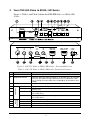
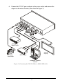
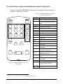
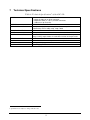
USER MANUAL
Model:
CSC-550
Video to SXGA / HD Scaler
For maximum results, use Comprehensive
Brand Premium High Resolution cables
and connectors.
Contents
1
2
3
4
5
6
6.1
6.2
Introduction
Getting Started
Overview
Your CSC-550 Video to SXGA / HD Scaler
Connecting the CSC-550 Video to SXGA / HD Scaler
Controlling the CSC-550
Controlling via the Front Panel Buttons
Using the CONTROL Buttons
1
1
1
3
4
6
6
6
6.2.1
6.2.2
6.2.3
The MAIN MENU
The PICTURE Menu
The SETUP Menu
6
7
7
6.3
7
Controlling via the Infra-Red Remote Control Transmitter
Technical Specifications
8
9
Figures
Figure 1: CSC-550 Video to SXGA / HD Scaler – Front and Rear View
Figure 2: Connecting the CSC-550 Video to SXGA / HD Scaler
Figure 3: Infra-Red Remote Control Transmitter
3
5
8
Tables
Table 1: CSC-550 Video to SXGA / HD Scaler Front Panel Features
Table 2: CSC-550 Video to SXGA / HD Scaler Rear Panel Features
Table 3: HD15 PINOUT for HD
Table 4: The MAIN MENU Features
Table 5: The PICTURE Menu Features
Table 6: The SETUP Menu Features
Table 7: Infra-Red Remote Control Transmitter Functions
Table 8: Technical Specifications of the CSC-550
i
3
4
4
6
7
7
8
9
1
Introduction
Congratulations on purchasing your CSC-550 Video to SXGA / HD Scaler.
This product is ideal for:
Projection systems in conference rooms, boardrooms, hotels and churches
Home theater up-scaling
The package includes the following items:
CSC-550 Video to SXGA / HD Scaler
Power adapter (12V DC input)
Infra red remote control transmitter
This user manual
2
Getting Started
We recommend that you:
Unpack the equipment carefully and save the original box and packaging
materials for possible future shipment
Review the contents of this user manual
3
Overview
The CSC-550 Video to SXGA / HD Scaler is a high quality converter for upscaling composite video, s-Video (YC), and SD component video to XGA1
and HD resolutions. It also has a computer graphics (XGA) input, which –
when selected, or when the machine is not powered - is routed directly
(bypassed) to the output. Video inputs are de-interlaced and scaled to the
selected PC or HDTV resolutions, as follows:
VGA (640x480)
SXGA (1280x1024)
720p
SVGA (800x600)
480p
XGA (1024x768)
576p
1080i
1 The terminology XGA is used throughout this manual, where this implies any RGBHV signal on an HD15 connector
having a resolution from VGA up to SXGA
1
The CSC-550 Video to SXGA / HD Scaler also features:
Automatic detection of NTSC, PAL-B, PAL-G, PAL-I, PAL-D, and
SECAM video standards
An On-Screen Display (OSD) for easy setup and adjustment, accessible
via the IR remote control and via the front-panel buttons
A high-performance adaptive 3D comb filter (for precise color
management)
Per-pixel motion compensated de-interlacing for artifact-free video images
Automatic detection for 3:2 pulldown for 24fps film source material
Frame rate conversion of 50Hz to 60Hz for PAL input signals
A Vertical Temporal (VT) Filter for removing jagged artifacts
Advanced color/luminance transient improvement circuitry
A PC Input connector for easy integration into an existing system
A built-in procamp for convenient signal adjustment
A non-volatile memory that retains the last settings used
The machine is fed from an external 12V DC source, making it suitable for
field operation.
Control your CSC-550:
Directly, via the front panel push buttons
Remotely, from the infra-red remote control transmitter
To achieve the best performance:
Connect only good quality connection cables, thus avoiding interference,
deterioration in signal quality due to poor matching, and elevated noise-levels
(often associated with low quality cables)
Avoid interference from neighboring electrical appliances and position
your CSC-550 away from moisture, excessive sunlight and dust
Caution – No operator-serviceable parts inside unit.
Warning – Use only the input power wall adapter that is
provided with this unit.
Warning – Disconnect power and unplug unit from wall
before installing or removing device or servicing unit.
2
4
Your CSC-550 Video to SXGA / HD Scaler
Figure 1, Table 1 and Table 2 define the CSC-550 Video to SXGA / HD
Scaler:
Figure 1: CSC-550 Video to SXGA / HD Scaler – Front and Rear View
Table 1: CSC-550 Video to SXGA / HD Scaler Front Panel Features
Feature
POWER Switch
RGB/RESET Button
3
4
5
IR Receiver
MENU Button
ENTER Button
7
8
9
10
11
INPUT
SELECTOR
6
CONTROL
#
1
2
+ Button
- Button
CV Button
YC Button
COMP. Button
SXGA Button
Function
Switch for turning the unit ON or OFF
Illuminates when the output resolution is set to RGB. Press to set output
to Y Pb Pr (the button no longer illuminates). Press and hold for more
than 3 seconds to reset to VGA. Press and hold for 10 seconds to reset
to 480p
Lights when receiving signals from the remote control transmitter
Displays the OSD menu (see section 6.2)
Press to accept changes and change the SETUP parameters (see
section 6.2.3)
Press to go up the menu list or adjust the PICTURE submenu values
(see section 6.2.2)
Press to go down the menu list or adjust the PICTURE submenu values
(see section 6.2.2)
Press to select the composite video source
Press to select the s-Video (YC) video source
Press to select the component video source
Press to select the SXGA source
3
Table 2: CSC-550 Video to SXGA / HD Scaler Rear Panel Features
Feature
Function
YC 4p Connector
CV RCA Connector
Y RCA Connector
CB RCA Connector
CR RCA Connector
SXGA PASS HD15 Connector
SXGA / HD OUT HD15 Connector
Connects to the s-Video source
Connects to the composite video source
19
12 VDC
5
Connecting the CSC-550 Video to SXGA / HD Scaler
INPUTS
#
12
13
14
15
16
17
18
1
Connects to the interlaced component video source
2
3
Connects to the VGA/Y, Pb, Pr source
Connects to the SXGA or HDTV (component video)
acceptor
+12V DC connector for powering the unit
Connect4 your CSC-550, as illustrated in the example in Figure 2:
1. Connect an s-Video source (for example, an s-Video camcorder) to the
YC INPUT 4p connector.
2. Connect a composite video source (for example, a composite video
player) to the CV INPUT RCA connector.
3. Connect a component video source (for example, a DVD player) to the Y,
Cb and Cr INPUT RCA connectors.
4. Connect an SXGA graphics source to the SXGA PASS INPUT HD15
connector5.
5. Connect the SXGA/HD OUT HD15 connector to a video acceptor (for
example, a plasma display) as follows:
When connecting to an XGA acceptor (RGBHV), then connect to
the acceptor’s XGA connector
When connecting to a component acceptor (Y, Cb, Cr), then
connect as shown in Table 3
Table 3: HD15 PINOUT for HD6
PIN #
1
2
3
Signal
Cr
Y
Cb
1 Not compatible with progressive scan Y, Pb, Pr or HDTV
2 For component video, connect all three connectors: Y, Cb, Cr (also known as YUV)
3 This PC input signal is not scaled, but is available for pass-through when the PC source is selected
4 You do not have to connect all the inputs, connect only those that are required
5 This PC input signal is not scaled, but is available for pass-through when the PC Source is selected
6 The PINOUT should be: PIN 1 = Cr, PIN 2 = Y and PIN 3 = Cb (with pins 6, 7 and 8 as ground respectively)
4
6. Connect the 12V DC power adapter to the power socket and connect the
adapter to the mains electricity (not shown in Figure 2).
Composite
Video Player
s-Video
Camcorder
Plasma
Display
DVD Player
Computer Graphics
Source
Figure 2: Connecting the CSC-550 Video to SXGA / HD Scaler
5
6
Controlling the CSC-550
The CSC-550 can be controlled directly via the front panel buttons (see section
6.1), via the OSD menu (see section 6.2), and/or remotely from the infra-red
remote control transmitter (see section 6.3).
6.1 Controlling via the Front Panel Buttons
The CSC-550 includes the following control front panel buttons:
An RGB/RESET button for setting the output to either RGB or Y, Pb, Pr
or resetting1 the resolution to VGA or 480p
CONTROL buttons, including the MENU, ENTER, + and – buttons
INPUT SELECTOR buttons for selecting the required input (CV, YC,
COMP. or SXGA)
6.2 Using the CONTROL Buttons
The CONTROL buttons let you control the CSC-550 via the OSD menu:
Press the MENU button to enter the menu2
Press the ENTER button to accept changes and to change the menu
settings
Press the + and – buttons to move through the OSD menu, which is
displayed on the video output, or adjust the PICTURE parameters
On the OSD menu, select EXIT to exit the menu.
6.2.1
The MAIN MENU
Table 4 defines the MAIN MENU features and functions.
Table 4: The MAIN MENU Features
Mode
Function
PICTURE
Set the picture parameters (contrast, brightness, color, hue, detail and reset), see
section 6.2.2
SOURCE
Select the desired input source: video, s-Video, Y, CB, CR or computer
RESOLUTION
After selecting the output type3, select between the RGB output resolutions (VGA,
SVGA, XGA or SXGA) or the YPbPr output resolutions (480p, 576p, 720p or 1080i)
SETUP
Select the aspect, output, 3D enhance, digital NR, display and HV output (see section
6.2.3)
INFORMATION Displays the source, resolution and software version
EXIT
Select to exit the menu
1 Press for 3 seconds to reset to VGA and press for 10 seconds to reset to 480p
2 The menu times out after 8 seconds
3 By pressing the RGB/RESET button or via the OSD menu
6
6.2.2
The PICTURE Menu
Table 5 defines the PICTURE menu.
Table 5: The PICTURE Menu Features
Parameter
Function
Range
Default
CONTRAST
Adjust the contrast
From 0 to 63
58
BRIGHT
Adjust the brightness
From 0 to 63
31
COLOR
Adjust the color
From 0 to 63
31
HUE
Adjust the hue
From 0 to 63
31
DETAIL
Adjust the sharpness
From 0 to 63
10
RESET
Select RESET and press ENTER to reset to the default parameters
EXIT
Select to exit to the MAIN MENU
6.2.3
The SETUP Menu
Table 6 defines the SETUP menu.
Table 6: The SETUP Menu Features
Parameter
1
ASPECT
Function
Select between STANDARD, 4:3 and 16:9
OUTPUT
Select a PC (RGB) output or an HDTV (Y, Pb, Pr) output
3D ENHANCE
DIGITAL NR
Turn the 3D comb filter function ON or OFF2
Turn the digital noise reduction function ON or OFF
DISPLAY
HV OUTPUT
Set to ON to display the input standard and the output resolution on the screen;
otherwise, set to OFF
Select ON to send H and V synchronization when Y, Pb, Pr is selected for the output3
EXIT
Select to exit to the MAIN MENU
1 STANDARD will output the signal in the same aspect ratio as the input aspect ratio. 4:3 and 16:9 will always output as 4:3
and 16:9 respectively, regardless of the input aspect ratio
2 When a video player or a non-standard video source is connected to the input, the output picture may jitter. If this occurs,
turn the 3D Comb Filter to OFF
3 H and V are always sent when RGB is selected at the output
7
6.3 Controlling via the Infra-Red Remote Control Transmitter
You can control the CSC-550 from the infra-red remote control transmitter,
as Figure 3 and Table 7 define:
Table 7: Infra-Red Remote Control
Transmitter Functions
VGA
SXGA
576p
SVGA
ASPECT
720p
XGA
480p
1080i
C-VIDEO
S-VIDEO
YPbCr
PC
PICTURE
RESET
MENU
3D
NR
ENTER
Figure 3: Infra-Red Remote Control
Transmitter
Keys
Function
POWER
Turn power ON or OFF
DISPLAY
Turn input standard and output
resolution information display ON or
OFF
C-VIDEO
Select the composite video input
S-VIDEO
Select the s-Video input
YCbCr
Select the component video input
PC
Select the input PC to loop-through
VGA
Set the output resolution to 640x480
SVGA
Set the output resolution to 800x600
XGA
Set the output resolution to 1024x768
SXGA
Set the output resolution to
1280x1024
480p
Set the output resolution to 852x480p
576p
Set the output resolution to 852x576p
720p
Set the output resolution to
1280x720p
1080i
Set the output resolution to
1920x1080i
ASPECT
Select the standard, normal (4:3) or
the wide (16:9) aspect ratio
PICTURE
RESET
Press and hold for 2 seconds to reset
all the ProcAmp settings (contrast,
brightness and so on)1
3D
Turn the 3D enhance feature ON or
OFF
NR
Turn the digital noise reduction feature
ON or OFF
MENU
Enter the OSD menu
ENTER
Press to accept changes and to
change SETUP parameters
Press to adjust the picture parameters
1 In some versions, you need to be within the PICTURE menu to do this
8
7
Technical Specifications
1
Table 8: Technical Specifications of the CSC-550
INPUTS:
OUTPUT:
OUTPUT RESOLUTIONS:
PROCESSING DELAY:
CONTROLS:
ADDITIONAL CONTROLS:
POWER SOURCE:
DIMENSIONS:
WEIGHT:
ACCESSORIES:
1 VGA/SVGA/XGA/SXGA on an HD15F connector
1 composite video on an RCA connector
1 component video (Y, Cb, Cr) on RCA connectors
1 s-Video on a 4p connector
1 RGB/YPbPr on an HD15F connector
VGA (640x480), SVGA (800x600), XGA (1024x768), SXGA
(1280x1024), HDTV: 480p, 576p, 720p, 1080i
2 frames
Front panel buttons and infra red remote for menu driven OSD control
Contrast, brightness, color, tint and sharpness; Resolution, output
image scaling, output mode, 3D comb filter function and aspect ratio
12V DC, 350mA
21.5cm x 16.3cm x 4.36cm (8.46” x 6.4” x 1.7”) W, D, H
0.25kg (0.55lb.) approx.
Power supply, IR remote control
1 Specifications are subject to change without notice
9