1
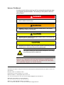
KeTop T40
Handheld Terminal
Siemens S5 Coupling
User’s Manual V 1.2
Notes on This Manual
At various points in this manual you will see notes and precautionary warnings regarding possible hazards. The meaning of the symbols used is explained below.
! DANGER
z
DANGER indicates an imminently hazardous situation which, if not avoided, will
result in death or serious injury.
! WARNING
z
WARNING indicates a potentially hazardous situation which, if not avoided,
could result in death or serious injury.
! CAUTION
z
CAUTION indicates a potentially hazardous situation which, if not avoided, may
result in minor or moderate injury.
CAUTION
z
CAUTION used without the safety alert symbol indicates a potentially hazardous
situation which, if not avoided, may result in property injury.
This symbol reminds you of the possible consequences of touching
electrostatically sensitive components.
Note
Notes on use of equipment and useful practical tips are identified by the
“Notice” symbol. Notices do not contain any information that draws attention to potentially dangerous or harmful functions.
© KEBA 2005
Specifications are subject to change due to further technical developments. Details presented may be subject to correction. All
rights reserved.
Document: version 1.2 / material no.: 61871
Filename: t40_s5_en.doc, last saving on: 10. 12. 2004
KEBA AG, Postfach 111, Gewerbepark Urfahr, A-4041 Linz
Tel.: ++43 / 732 / 70 90-0, Fax: ++43 / 732 / 73 09 10, E-Mail: [email protected], www.keba.com
KEBA GmbH, Ulmer Straße 123, D-73037 Göppingen
Tel.: ++49 / 7161 / 97 41-0*, Fax: ++49 / 7161 / 97 41-40
KEBA Corp., 100 West Big Beaver Road, Troy, MI 48084
Tel. ++1 / 248 / 526 - 0561, Fax: ++1 / 248 / 526 - 0562, E-Mail: [email protected]
Siemens S5 Coupling
Contents
History
Modification
from / to
V1.0
V1.0/V1.1
Date
Aug. 02
Oct.03
Modified
pages
10,14
V1.1/V1.2
12-2004
all
Author
First edition
sam
sam
In all drawings „example of connection“ CB111 has been
changed to KeTop CB211.
User's Manual, version: 1.2 / material no.: 61871
© KEBA 2005
Description
New Layout
sam
3
Contents
4
KeTop T40
User's Manual, version: 1.2 / material no.: 61871
© KEBA 2005
Siemens S5 Coupling
Contents
Contents
1
Introduction.....................................................................................................................................7
2
Connection ......................................................................................................................................8
Connection to Siemens Programmer Port ................................................................................9
Connection to a Siemens CP525/524 Module........................................................................12
3
Configuration of KeTop................................................................................................................15
Configuration Software ...........................................................................................................15
Configuration...........................................................................................................................15
Creating Texts with Variables .................................................................................................16
4
KeTop Power-Up Phase after Turning On..................................................................................18
Coupling to Siemens CP525/524............................................................................................19
Coupling to Siemens S5 Programmer Port.............................................................................20
5
Definition of Data Block ...............................................................................................................22
KeTop T40 -> PLC ..................................................................................................................24
PLC -> KeTop T40 ..................................................................................................................26
Graphic Functions...................................................................................................................32
6
Error Messages.............................................................................................................................42
User's Manual, version: 1.2 / material no.: 61871
© KEBA 2005
5
Siemens S5 Coupling
Introduction
1 Introduction
This document is a supplement to the User's Manual "KeTop T40 Handheld Terminal – General Information" and exclusively refers to Siemens S5
couplings.
The following chapters describe the usage of the KeTop on the Siemens S5
programmer port and on the Siemens communication processors
CP525/524.
The data are exchanged between the KeTop T40 and the PLC by reading
and writing a freely selectable data block (DB) with a minimum length of 40
data words (DW).
This data block must be defined and provided in the PLC.
For a detailed description of the configuration of the KeTop, the basic functions and the key labelling of the KeTop, please refer to the User's Manual
"KeTop T40 Handheld Terminal – General Information".
User's Manual, version: 1.2 / material no.: 61871
© KEBA 2005
7
Connection
KeTop T40
2 Connection
The KeTop T40 can be connected serially to the Siemens control via a programmer port (protocol AS511) of a S5 central processor or via a communication processor CP525/524 (protocol RK512).
In case the KeTop T40 is connected to the programmer port and the Siemens programmer is used as well, the KeTop T40 must be adapted for the
programmer multiplex mode.
The KeTop is connected to the S5 via the interface COM2 of the KeTop
T40 which can be configured as RS-232-C or RS-422-A by means of DIP
switches.
Also refer to the User's Manual "KeTop T40 Handheld Terminal – General
Information", chapter "Connection".
Since the S5 programmer port is a 20mA CL interface and the KeTop T40
only features a RS-232-C or RS-422-A interface (COM2), an interface converter must be used.
8
User's Manual, version: 1.2 / material no.: 61871
© KEBA 2005
Siemens S5 Coupling
Connection
Connection to Siemens Programmer Port
For the communication via the data block, no function blocks are required.
Direct Connection to KeTop T40
The following two drawings show the two connection variants (RS-232-C,
RS-422-A) of the Siemens S5 to the COM2 interface of the KeTop T40.
RS-232-C
S5-PG SI1/SI2
20 mA CL
SUB-D 15-pin
female connector
RXD
9
RXD
2
TXD
7
TXD
6
KeTop T40 COM2 RJ45
Twisted pairs
of wires
Interface converter
20 mA CL
S6
TXD
1
2
RXD
RS-232-C
3
4
GND
Current direction
5
6
7
8
Example of connection: Current Loop to Siemens S5 programmer port via COM2 RS-232-C
RS-422-A
S5-PG SI1/SI2
20 mA CL
SUB-D 15-pin
female connector
KeTop T40 COM2 RJ45
Twisted pairs
of wires
Interface converter
S6
A
1
2
B
2
TXD
7
A'
3
TXD
6
RXD
9
RXD
20mA CL
RS-422-A
4
5
Current direction
B'
6
7
8
Example of connection: Current Loop to Siemens S5 programmer port via COM2 RS-422-A
User's Manual, version: 1.2 / material no.: 61871
© KEBA 2005
9
Connection
KeTop T40
Connection via Connection Box KeTop CB211
The S5 programmer port can be connected to the X3 of the connection box
KeTop CB211 via the interface converter.
The following drawings show the two connection variants (RS-232-C, RS422-A) of the Siemens S5 to the connection box KeTop CB211.
RS-232-C
S5-PG SI1/SI2
20 mA CL
SUB-D 15-pin
female connector
RXD
9
RXD
2
TXD
7
TXD
6
Connection box KeTop CB211
Twisted pairs
of wires
X3
1
Interface converter
TxD
20 mA CL
RS-232-C
RxD 2
RXD
3
GND
TxD 4
5
GND 6
Current direction
Example of connection: CL to Siemens S5 programmer port via connection box, RS-232-C
RS-422-A
Connection box KeTop CB211
S5-PG SI1/SI2
20 mA CL
SUB-D 15-pin
female connector
RXD
9
RXD
2
TXD
7
Twisted pairs
of wires
20mA CL
TXD
RS-422-A
6
X3
1
Interface converter
A (TxD-)
A' (RXD-) 2
B (TxD+)
B' (RXD+) 3
A' (RxD-)
A (TXD-) 4
B' (RxD+)
B (TXD+) 5
6
Current direction
Example of connection: CL to Siemens S5 programmer port via connection box, RS-422-A
10
User's Manual, version: 1.2 / material no.: 61871
© KEBA 2005
Siemens S5 Coupling
Connection
Multiplex Mode
It is possible to operate the KeTop T40 and the Siemens programmer simultaneously on the S5 programmer port.
In this case, one interface (COM2) of the KeTop T40 is connected to the
Siemens control and the other interface (COM1) to the Siemens programmer. The interfaces are assigned during configuration.
All commands of the programmer are transmitted to the Siemens control
via the handheld terminal.
KeTop T40
S5 programmer
Siemens Simatic S5 AG
KETOP
COM1
COM2
Programmer port
S5 programmer to programmer port via the KeTop T40 (through multiplex mode)
User's Manual, version: 1.2 / material no.: 61871
© KEBA 2005
11
Connection
KeTop T40
Connection to a Siemens CP525/524 Module
For the communication between the CPU and the CP module, 3 function
blocks are required:
Function block
SYNCHRON
SEND ALL
RECEIVE ALL
Function
synchronizes CP
and CPU
transmits data from the CPU to
the CP
transmits data from the CP to the
CPU
S5 115U
FB249
S5 135U
FB125
S5 150U
FB185
S5 155U
FB125
FB244
FB120 /
FB126
FB121 /
FB127
FB180
FB120 /
FB126
FB122 /
FB127
FB245
FB181
In this case the function blocks SEND ALL and RECEIVE ALL must be
called cyclically by the PLC program.
At the AG 115U / CPU 943, these function blocks are part of the operating
system and therefore do not need any space in the user memory.
At the AG 135U / CPU 922 (R-processor), the block headers are stored on
floppy disks and must be loaded into the AG. At the AG 150U and the
AG 155U, the function blocks are available on floppy disks as STEP5 program and must be loaded into the AG. In this case the function blocks are
not part of the operating system and must, therefore, be ordered separately
at SIEMENS.
The definitions of the procedure 3964R and of the interpreter RK512 are
taken from the manual
„SIEMENS SIMATIC S5 - COM 525 for CP 525 and CP 524“.
At the latest CPUs of the S5 (945, 928B,...) series, the protocol RK512 can
be operated via a plug-in interface module. The programming differs to that
of the CP525 and is described in the corresponding Siemens manual.
For transmitting data, the procedure 3964R is used. In this case transmission errors are recognized by a vertical parity check and block check characters.
For controlling the protocol and interpreting the transmitted data, the interpreter RK 512 is used. In this case the KeTop T40 has the higher priority,
the CP module the lower priority.
Direct Connection to the KeTop T40
The following two drawings show both connection variants (RS-232-C, RS422-A) of the Siemens S5 to the COM2 interface of the KeTop T40.
12
User's Manual, version: 1.2 / material no.: 61871
© KEBA 2005
Siemens S5 Coupling
Connection
RS-232-C
CP525/524 SI1/SI2
20 mA CL
SUB-D 25-pin
female connector
KeTop T40 COM2 RJ45
Twisted pairs
of wires
+RXD 13
Interface converter
20 mA CL
S6
TXD
-RXD 14
1
2
RXD
-TXD 19
RS-232-C
3
4
+TXD 10
GND
Current direction
5
6
7
8
Example of connection: Current Loop to Siemens CP525/524 via COM2 RS-232-C
RS-422-A
CP525/524 SI1/SI2
20 mA CL
SUB-D 25-pin
female connector
KeTop T40 COM2 RJ45
Twisted pairs
of wires
+RXD 13
Interface converter
20 mA CL
-RXD 14
-TXD 19
S6
A
1
B
2
A'
3
RS-422-A
4
+TXD 10
5
Current direction
B'
6
7
8
Example of connection: Current Loop to Siemens CP525/524 via COM2 RS-422-A
User's Manual, version: 1.2 / material no.: 61871
© KEBA 2005
13
Connection
KeTop T40
Connection via Connection Box KeTop CB211
The S5 communication processor can be connected to the X3 of the connection box KeTop CB211 via the interface converter.
The following drawings show the two connection variants (RS-232-C, RS422-A) of the Siemens S5 to the connection box CB211.
RS-232-C
CP525/524 SI1/SI2
20 mA CL
SUB-D 25-pin
female connector
Connection box KeTop CB211
Twisted pairs
of wires
X3
1
Interface converter
+RXD 13
TxD
20 mA CL
RxD 2
-RXD 14
RxD
3
-TXD 19
GND
TxD 4
RS-232-C
+TXD 10
5
GND 6
Current direction
Example of connection: CL to Siemens CP525/524 via connection box CB211, RS-232-C
RS-422-A
Connection box KeTop CB211
CP525/524 SI1/SI2
20 mA CL
SUB-D 25-pin
female connector
Twisted pairs
of wires
+RXD 13
20 mA CL
-RXD 14
-TXD 19
RS-422-A
+TXD 10
X3
1
Interface converter
A (TxD-)
A' (RXD-) 2
B (TxD+)
B' (RXD+) 3
A' (RxD-)
A (TXD-) 4
B' (RxD+)
B (TXD+) 5
6
Current direction
Example of connection: CL to Siemens CP525/524 via connection box CB211, RS-422-A
14
User's Manual, version: 1.2 / material no.: 61871
© KEBA 2005
Siemens S5 Coupling
Configuration of KeTop
3 Configuration of KeTop
Configuration Software
For setting the device configuration and generating the texts, KEBA supplies a configuration software which is executable under Windows.
The configuration is described in detail in the User's Manual "KeTop T40
Handheld Terminal – General Information" (e.g. functions for editing the
keypad assignment and for loading the configuration) and, in general, can
also be used for the Siemens S5 coupling.
Therefore the following chapters only describe the specific details of the
Siemens S5 coupling.
Configuration
Menu items
Protocol selection
First select whether the KeTop T40 is connected to the programmer port
„Serial S5 PG (AS511)“ or to a communication processor „Serial S5 CP
(RK512)“.
Serial S5 CP (RK512) or Serial S5
PG (AS511)
Selection of requested Siemens coupling and
configuration of interface.
PLC interface
Selection of requested interface and baudrate.
AS511: fixed 9600 baud
RK512: 9600, 19200, 38400, 57600, 115200
baud.
Data block
Entry of data block type (DB or DX), data block
number and ID. The ID (max. of 4 characters)
must correspond to the ID in the data block (also
refer to "DW16, DW17: ID (DB-ID) ".
User's Manual, version: 1.2 / material no.: 61871
© KEBA 2005
15
Configuration of KeTop
KeTop T40
Creating Texts with Variables
At the Siemens coupling, the number of the variable corresponds to the
data word of the data block. The data word contains the corresponding PLC
variable. Each data word from DW 34 on can be used. A write access of
the handheld terminal to variables located in the range from DW0 to DW33
may lead to undefined statuses in the KeTop T40 and should be avoided
therefore.
Text memory (programming software)
No.
0
:
Text
DR/DW/DD:
Data type:
Format:
I/O type:
:
n
DR
DW
DD
right-side data byte
data word
double data word
The Siemens format of a data word is defined in the programming software
using the parameters "data type" and "format" according to the following
table:
Siemens
Format
KG
KM
KB
KF
KH
KC
Handheld terminal
Data type
FLOAT32
UINT8
UINT8
SINT16
UINT16
STRING
Format
DEC
BIN
DEC
DEC
HEX
TEXT
The I/O type of the variable determines whether the variable is an input (IN),
an output (OUT) or an input/output variable (IN/OUT) (for details and examples, please refer to the User's Manual "KeTop T40 Handheld Terminal –
General Information").
16
User's Manual, version: 1.2 / material no.: 61871
© KEBA 2005
Siemens S5 Coupling
Configuration of KeTop
Example
Programming software: "Edit text lines"
Line
0
Display
PUMP 1:
50%
1
2
3
No.
0
1
2
3
4
:
Data block DB x
Text
PUMP 1: ###%
DW:34
Data type:UINT8
Format:DEC
I/O type:OUT
Var.no.:
Line
0
1
2
3
1
2
3
4
50
:
:
1999
Handheld Terminal
DW
26
27
28
29
34
35
36
37
Siemens Simatic S5
Example of a text display with an output variable
Output variables are cyclically updated. Input variables are sent to the PLC
after confirmation by Enter.
User's Manual, version: 1.2 / material no.: 61871
© KEBA 2005
17
KeTop Power-Up Phase after Turning On
KeTop T40
4 KeTop Power-Up Phase after Turning On
The handheld terminal carries out a power-on self-test. For details on the
test steps, refer to the User's Manual "KeTop T40 Handheld Terminal –
General Information".
► The first part of the test is identical for each KeTop T40 coupling and
thus described in the User's Manual "KeTop T40 Handheld Terminal –
General Information".
► Then the Siemens S5 configuration data are loaded.
The following message is displayed:
S5
Vx.x
Initializing...
In case of an error, the handheld terminal remains in this condition.
► After successfully loading the Siemens S5 configuration data, different
messages are displayed depending on the coupling used.
18
User's Manual, version: 1.2 / material no.: 61871
© KEBA 2005
Siemens S5 Coupling
KeTop Power-Up Phase after Turning On
Coupling to Siemens CP525/524
S5 CP RK512
Vx.x
DBxxxID: “........“
CHANNEL: COMn, mmmmm
ooooo,E,8,1
x.x
xxx
“........“
n
ooooo
E
mmmmm
Program version
DB or DX number
ID (4 bytes), e.g.: „KEBA"
Number of interface port
Baudrate (9600, 19200, 38400, 57600, 115200 Baud)
Parity always set to even
Type of interface ( RS232 or RSxx2 for RS232/RS422)
► The next display depends on the following conditions:
Connection to PLC OK
No
Yes
ID in PLC corresponds
to ID in KeTop T40.
No
Yes
Display of texts
(text numbers)
activated by the PLC
Error: Wrong DB-ID
Communication
Timeout
after approx. 12 sec.
For the description of the errors, please refer to the chapter "Error Messages".
User's Manual, version: 1.2 / material no.: 61871
© KEBA 2005
19
KeTop Power-Up Phase after Turning On
KeTop T40
Coupling to Siemens S5 Programmer Port
► Depending on whether the handheld terminal is operated in the
multiplex mode or not, the following message appears on the display:
Without multiplex function
S5 PG AS511
Vx.x
DBxxxID: “........“
CHANNEL: COMn, mmmmm
ooooo,E,8,1
x.x
xxx
“........“
n
ooooo
E
mmmmm
oder
With multiplex function
S5 PG-MUX AS511 Vx.x
DBxxxID: “........“
CHANNEL: COMn, mmmmm
ooooo,E,8,1
Program version
DB or DX number
ID (4 bytes), e.g.: „KEBA"
Number of interface port
Baudrate (9600, 19200, 38400, 57600, 115200 Baud)
Parity always set to even
Type of interface ( RS232 or RSxx2 for RS232/RS422)
► After approx. 3 seconds, the system parameters are requested from the
PLC. The following message is displayed:
Like before
Vx.x
Wait for
S5 Systemparameter
20
User's Manual, version: 1.2 / material no.: 61871
© KEBA 2005
Siemens S5 Coupling
KeTop Power-Up Phase after Turning On
► The next display depends on the following conditions:
Connection to PLC OK
No
Yes
ID in PLC corresponds
to ID in KeTop T40.
No
Yes
Display of texts
(text numbers)
activated by the PLC
Error: Wrong DB-ID
Communication
Timeout
For the description of the errors, please refer to the chapter "Error Messages".
User's Manual, version: 1.2 / material no.: 61871
© KEBA 2005
21
Definition of Data Block
KeTop T40
5 Definition of Data Block
The data words DW0 to DW3 of this data block are cyclically written by the
KeTop T40, the data words DW16 to DW46 are cyclically read. The range
from DW37 on can be used for write/read accesses of variables if necessary (see chapter "DW37 – DW46: Variables"):
S7
S5
DBW0
DW0
15
14
13
12
DL
11
DR
10
9
8
7
6
5
4
3
2
1
0
PLC
Bit number
Status
HT active
Edit mode
Cyclic reading
of user program
Cyclic writing
of HT
HT
Edit line
DBW2
DW1
DBW4
DW2
16
15
14
13
12
11
10
9
8
7
6
5
4
3
2
1
DBW6
DW3
32
31
30
29
28
27
26
25
24
23
22
21
20
19 18
17
Internal ASCII-Code
Key code
Key status
DBW8
DW4
DBW10
:
DBW30
DW5
:
DW15
DBW32
DW16
1st character
2nd character
DBW34
DW17
3rd character
4th character
DBW36
DW18
reserved
DB-ID
DB-ID
Control word
Activate command interface
Check RUN counter of PLC
Beep
Keyclick depress
Keyclick release
Disable Menu
Text output (text number)
DBW38
RUN counter of PLC
DW19
DBW40
DW20
DBW42
DW21
DB
DBW44
DW22
DW
DBW46
DBW48
DW23
DW24
DBW50
DW25
DBW52
DW26
16
15
14
13
12
11
10
9
8
7
6
5
4
3
2
1
DBW54
DW27
32
31
30
29
28
27
26
25
24
23
22
21
20
19 18
17
DBW56
DW28
34
33
DBW58
:
DBW72
DW29
:
DW36
0 ... n
DBW74
DW37
0 ... n
DBW76
DW38
0 ... n
DBW78
DW39
0 ... n
DBW80
DW40
0 ... n
DBW82
DW41
0 ... n
DBW84
DW42
0 ... n
DBW86
DW43
0 ... n
DBW88
DW44
0 ... n
DBW90
DW45
0 ... n
DBW92
DW46
0 ... n
DBW94
DW47
0 ... n
Variable
DBW96
:
DBWxxx
DW48
:
DWxxx
0 ... n
Variable
:
Variable
Number of commands
Totaly number of words
Command interface
14
13
12
11
10
9
8
7
6
5
4
3
2
1
30
29
28
27
26
25
24
23
22
21
20
19 18
17
34
33
0 ... n
0 ... n
LEDs: on/off
LEDs: flashing mode
Line 0
:
Line 7
Cyclic writing of
user program
15
31
Text number
16
32
10 variables
Acyclic
writing and
reading
Acyclic writing
and reading
Acyclic writing
Cyclic reading
of HT
Handshake bits: 11: execute command(s) (start command) (PLC)
00: execution of command(s) without errors (HT)
01: an error occured while the command(s) was (were) executed (HT)
Freely selectable data block with data word definition
22
User's Manual, version: 1.2 / material no.: 61871
© KEBA 2005
Siemens S5 Coupling
Definition of Data Block
Note on use of SIEMENS S7 Simatic control
If a SIEMENS Simatic S7 control is connected, the data word addresses
must be doubled.
In STEP 7, the data operands and data blocks are addressed byte by byte
(compared to STEP 5 where the addressing is done word by word). Therefore the addresses of the data operands must be converted accordingly:
DW [n]
STEP 5
DL [n]
15
14
13
12
11
DR [n]
10
9
8
7
6
5
4
3
2
1
0
2
1
0
DBW [2n]
STEP 7
DBB [2n]
7
6
5
4
3
DBB [2n+1]
2
1
0
7
6
5
4
3
Compared to STEP 5, the address of a data word will be doubled in STEP
7. In STEP 7 the division into right and left data byte does not exist any
more. The numbering of the bits is from 0 to 7 in both cases.
User's Manual, version: 1.2 / material no.: 61871
© KEBA 2005
23
Definition of Data Block
KeTop T40
KeTop T40 -> PLC
DW0: Status
Bit 0 - 3:
Edit line
If the edit mode is active (bit 4 = 1), these 4 bits contain the current input
line. The value ranges from KH xxx0 (line 0) to KH xxx7 (line 7).
Example
DW9 = KH xxx1
Line
index: 0 Length:
1 Width:
2
3 Surface:
_ _ _
_ _ _
The cursor stands in the second line (line index 1).
Bit 4:
Edit mode
This bit signalizes if the edit mode is activated in the handheld terminal.
Bit 4 = 1:
In this case, the current line in which the cursor is located is contained in the
bits 0-3.
Edit mode not active. The bits 0-3 are 0.
Bit 4 = 0:
Bit 5:
HT active bit
The PLC can use the active bit as sign of life from the KeTop 40. When the
bit changes from 0 to 1, the PLC can recognize a write access of the HT (to
DW0 - DW15). Following that, the PLC can reset the bit.
DL1: Internal ASCII Code
To each key an internal ASCII code is assigned. This assignment is fixed.
While a key is pressed on the KeTop T40 the corresponding ASCII code is
entered into DL0. If several keys are pressed simultaneously the ASCII
code of the key pressed at last will be entered. If no key is pressed 0 will be
entered.
DR1: Key Code
While a key is pressed on the KeTop T40, the corresponding USER code is
entered into DR0. This user-specific key code can be defined during configuration. If no key is pressed 0 will be entered.
24
User's Manual, version: 1.2 / material no.: 61871
© KEBA 2005
Siemens S5 Coupling
Definition of Data Block
DW2, DW3: Key Status
These data words contain the bit-coded map of all keys pressed on the KeTop T40 at the moment. The 32 keys are represented by two data words.
One data bit is assigned to each key.
User's Manual, version: 1.2 / material no.: 61871
© KEBA 2005
25
Definition of Data Block
KeTop T40
PLC -> KeTop T40
DW16, DW17: ID (DB-ID)
To make sure that a handheld terminal does not write to a data block that is
not destined for communication, an ID must be defined in the handheld
terminal as well as in the DB.
The ID for the handheld terminal is entered in the programming software after selecting the protocol. Then the ID is loaded together with the entire
program from the PC to the handheld terminal where it is stored in the flash
memory.
In the data block, the ID must be entered into the data bytes DL16 to DR17.
Then the handheld terminal cyclically reads this data range and checks if
the ID corresponds to the ID in the flash memory.
The user must enter the ID into the corresponding data words of the PLC. If
the two entries do not correspond to one another the error message „Error: Wrong DB-ID“ will be displayed on the KeTop T40.
DW 16
DW 17
DL
1st character
3rd character
DR
2nd character
4th character
Example
ID: „KEBA“
DW 16
DW 17
26
DL
K (4BH)
B (42H)
DR
E (45H)
A (41H)
User's Manual, version: 1.2 / material no.: 61871
© KEBA 2005
Siemens S5 Coupling
Definition of Data Block
DW18: Control Word
Bit 0:
Bit 0 = 0:
Bit 0 = 1:
Bit 1:
Bit 1 = 0:
Bit 1 = 1:
Bit 2:
Bit 2 = 0:
Bit 2 = 1:
Bit 3:
Bit 3 = 0:
Bit 3 = 1:
Bit 4:
Bit 4 = 0:
Bit 4 = 1:
Bit 5:
Bit 5 = 0:
Bit 5 = 1:
Bit 6:
Bit 6 = 0:
Bit 6 = 1:
Test output
This diagnostic function can be activated to control the text numbers entered in DW29 - DW36.
The message texts specified in DW29 to DW36 will be displayed on the
KeTop T40.
The text numbers entered in DW29 to DW36 will be displayed on the KeTop T40 as decimal numbers.
Disable Menu
This diagnostic function can be activated to control the text numbers entered in DW29 - DW36.
The call of the main menu by pressing the keys 1 and 2 is enabled.
The call of the main menu by pressing the keys 1 and 2 is disabled.
Keyclick release
When a key is released on the KeTop T40, a beep is output for 20 ms.
No keyclick when key is released.
Keyclick when key is released.
Keyclick depress
When a key is pressed on the KeTop T40, a beep is output for 20 ms.
No keyclick when key is pressed.
Keyclick when key is pressed.
Beep
For direct activation of the buzzer installed in the KeTop T40.
Buzzer off.
Buzzer on.
Check RUN counter of PLC
Used to enable the checking of the RUN counter of the PLC.
Checking of „RUN counter of PLC“ disabled.
Checking of „RUN counter of PLC“ enabled.
Command interface
Used to activate the command interface.
Command interface inactive.
Command interface active.
DW19: RUN Counter of PLC
This 16-bit value must be incremented continuously by the PLC program.
This enables the HT to check the RUN state of the PLC program. If this
value does not change for longer than 1 second an error message will be
displayed on the HT. This check function is activated via the bit „Check
RUN counter of PLC“ (DW18, bit 5).
DW20, DW21 and DW22: Command Interface
Via the command interface, one or more commands can be issued to the
KeTop T40 as kind of a „batch job“.
User's Manual, version: 1.2 / material no.: 61871
© KEBA 2005
27
Definition of Data Block
KeTop T40
The command interface is enabled and disabled via the bit 6 contained in
the control word (DW 18).
Bit 6 = 0
command interface inactive
Bit 6 = 1
command interface inactive
The command interface is divided into two data areas:
One area (DW20, DW21 and DW22) the HT cylically reads and one area
that will only be read if one or more commands are issued to the HT.
DW18
1
Handshake bits
DW20
x
x
x
x
x
x
Control word
Activate command interface
Number of commands
DW21
DB
DW22
DW
Total number of words
DB
DW
1st command
Number of words
18
5
Parameter
2nd command
Number of words
Parameter
3nd command
8
Number of words
2
Parameter
The number of words per command can be higher than the associated
number of parameter words actually needed.
Therefore memory within a string of commands can be reserved for the entry of commands with different lengths.
Example:
1st command (constant) =
2nd command (variable) =
rd
3 command (constant) =
circle
a) ellipse
b) line
c) period
rectangle
(number of words=4)
(number of words =5)
(number of words =4)
(number of words =2)
(number of words =5)
or
28
User's Manual, version: 1.2 / material no.: 61871
© KEBA 2005
Siemens S5 Coupling
1st command (constant) =
2nd command =
3rd command (constant) =
Definition of Data Block
circle
(number of words =4)
text with different length, (number of words =9)
e.g.: “alarm“ or “warning“
rectangle
(number of words =5)
The commands are issued to the KeTop T40 through the setting of both
handshake bits.
Setting the handshake bits from the PLC user program:
11
execute command(s) (start command)
Setting the handshake bits from the handheld terminal:
00
01
execution of command(s) without errors
an error occurred while the command(s) was (were) executed
User's Manual, version: 1.2 / material no.: 61871
© KEBA 2005
29
Definition of Data Block
KeTop T40
DW23 - DW25: Turn On/Off the LEDs
Setting data bits in this data word turns on the corresponding LEDs on the
KeTop T40.
0 = LED off
1 = LED on
Notice
The LEDs used in the handheld terminal can be switched to a flashing
mode (flashmap) or a lighting mode (bitmap).
LED bitmap
0
0
1
1
LED flashmap
0
1
1
0
LED state on KeTop T40
LED is off
LED is flashing
LED is flashing
LED is on
DW26 – DW 28: Switch LEDs to the flashing mode
Setting data bits in these data words switches the corresponding LEDs on
the KeTop T40 to the flashing mode. The flashing frequency is 2 Hz.
0 = LED is not flashing
1 = LED is flashing
30
User's Manual, version: 1.2 / material no.: 61871
© KEBA 2005
Siemens S5 Coupling
Definition of Data Block
DW29 - DW36: Text Number Line 0 – 7
In the flash memory of the KeTop T40, text lines consisting of 40 ASCII
characters each can be stored. The text lines are numbered from 0 to n.
They are called by the PLC with the number entered in the programming
software.
The maximum number of texts can be defined in the programming software.
A data word of the data block is assigned to each display line. When a text
number is entered into the corresponding data word, the text assigned to
this number in the programming software will be displayed.
If a message text not defined is called either a blank line or the message
" Invalid text: xxxx" will be displayed.
DW37 – DW46: Variables
The handheld terminal cyclically reads the data words DW16 to DW46.
Variables frequently used should be contained in this range of data words
to avoid additional read accesses to the PLC:
For each variable out of this range, an additional read access is required.
For example, a text combination that displays at the same time 4 variables
from 4 different positions in the DB needs 5 times the time needed for a text
combination of which all variables are in the range from DW37 to DW46.
User's Manual, version: 1.2 / material no.: 61871
© KEBA 2005
31
Definition of Data Block
KeTop T40
Graphic Functions
The graphic functions are activated from the control. The functions enable
displaying a text and drawing graphical elements (line, circle, rectangle and
ellipse) at any position of the KeTop T40 display (pixel-oriented).
x
y position
x position
0 1 2 3 4 5
y
0
1
2
3
4
5
6
7
Letter A in standard size at x/y position 0/0 of HT display
The graphic functions on the KeTop T40 are activated via the command interface (see chapter "DW20, DW21 and DW22: Command Interface").
Graphical Elements
The elements circle, rectangle and ellipse can also be represented as filled
areas. To delete a graphical element, draw the same element of the same
size, at the same position and in inverse color.
If you position graphical elements over existing texts or bitmaps, these texts
and bitmaps will be overwritten.
32
User's Manual, version: 1.2 / material no.: 61871
© KEBA 2005
Siemens S5 Coupling
Definition of Data Block
Pixel (B0H)
This command enables representing a single pixel at the specified x/y position of the HT display.
Command interface
x/y
Command:
B0H
2
x
Parameter
y
Line (B1H)
This command enables representing a line on the HT display according to
the specified x/y coordinates.
Command interface
x0/y0
B1H
4
x0
Parameter
y0
x1
x1/y1
User's Manual, version: 1.2 / material no.: 61871
© KEBA 2005
y1
33
Definition of Data Block
KeTop T40
Rectangle (B2H)
This command enables representing a rectangle on the HT display according to the specified x/y coordinates.
Command interface
x0/y0
Command:
B2H
5
x0
y0
Parameter
x1
x1/y1
y1
fill
fill
0H
1H
graphic not filled
graphic filled
Circle (B3H)
This command enables representing a circle on the HT display at the specified x/y position with the radius r.
Command interface
Command:
B3H
4
x
x/y
r
y
Parameter
r
fill
fill
0H
1H
34
graphic not filled
graphic filled
User's Manual, version: 1.2 / material no.: 61871
© KEBA 2005
Siemens S5 Coupling
Definition of Data Block
Ellipse (B4H)
This command enables representing an ellipse on the HT display at the
specified x/y position with the radiuses rx and ry.
Command interface
Command:
B4H
ry
5
x
x/y
y
rx
Parameter
rx
ry
fill
fill
0H
1H
graphic not filled
graphic filled
Clear window (B8H)
This command enables clearing a rectangular area on the HT display according to the specified x/y coordinates.
Command interface
x0/y0
Command:
B8H
4
x0
Parameter
y0
x1
ABCDEFG
x1/y1
y1
This command corresponds to the drawing of a filled rectangle with the set
background color.
User's Manual, version: 1.2 / material no.: 61871
© KEBA 2005
35
Definition of Data Block
KeTop T40
Set colors (B9H)
This command enables setting the foreground and background color (at
present only black or white) for all following graphical elements and graphical texts. The color remains active until another color is set.
Command interface
Command:
B9H
1
Parameter:
fg
bg
fg (foreground)
0H
FFH
white
black
bg (background)
0H
FFH
white
black
Set line type (BAH)
This command is used to set a line type on which all other graphical elements are based. This setting remains valid until a new line type is defined.
Command interface
Command:
Parameter:
BAH
1
Bitmap of line
Examples of line types:
Bitmap of line:
Pixels on display:
Line type:
1 1 1 1 1 1 1 1 1 1 1 1 1 1 1 1
Bitmap of line:
Pixels on display:
Line type:
1 1 1 1 1 0 0 0 1 1 1 1 1 0 0 0
Bitmap of line:
Pixels on display:
Line type:
1 1 1 1 0 1 1 0 1 1 1 1 0 1 1 0
Notice
When defining a line type take care to arrange several identical bitmaps
one after the other. If you choose an unsuitable bitmap the line might get irregular.
Display bitmap (BBH)
36
User's Manual, version: 1.2 / material no.: 61871
© KEBA 2005
Siemens S5 Coupling
Definition of Data Block
This command enables displaying the contents of a Windows bitmap file
from the bitmap memory of the KeTop according to the specified x/y coordinates.
The maximum size of the bitmaps is limited by the size of KeTop T40 display (128x64 pixels).
Command interface
x/y
Command:
BBH
4
Bitmap no. H
Parameter
Bitmap no. L
x
y
During configuration, identification numbers are assigned to the bitmaps.
User's Manual, version: 1.2 / material no.: 61871
© KEBA 2005
37
Definition of Data Block
KeTop T40
Graphical Text
These texts must be prepared in the PLC and can then be displayed on the
handheld terminal with the command B5H.
The text can be placed freely on the display. The text characters may be
represented in double height or double width. As standard the characters
are displayed in the format 5 x 7 pixels (incl. space 6 x 8 pixels). So characters with a double height have a format of 5 x 14 pixels (incl. space 6 x 16
pixels) and characters with a double width 10 x 7 pixels (incl. space 12 x 8
pixels).
Displaying a character means that the area for the character is cleared and
then the character is written into the empty field. An existing graphic or bitmap representation will be deleted at this position.
Notice
A) Programmed texts stored in the HT can only be displayed in lines or columns. These texts cannot be displayed at any pixel position or with a larger
size.
B) For graphical texts that are directly sent from the PLC to the handheld
terminal display, no editor function is available. That means the HT will not
correctly interpret symbols (___, ###) for the input and output of variables.
38
User's Manual, version: 1.2 / material no.: 61871
© KEBA 2005
Siemens S5 Coupling
Definition of Data Block
Text (B5H)
This command enables representing a maximum of 40 text characters at
the specified x/y position of the HT display (provided the characters are not
displayed with a double width and begin at the pixel column 0).
The text is displayed up to the end of the line (no line folding and no continuation in the next line).
4 + (length of text+1) / 2
Command interface
Command:
B5H
11
x
y
Size of charcter
Text attribut
Length of text (13 in example)
'D'
'r'
'u'
'c'
'k'
' '
'z'
'u'
' '
'g'
'r'
'o'
'ß'
x,y
Position of text on HT display
Font size
This parameter defines the size of the characters on the HT
display. The following settings are possible:
00H ... normal
01H ... double height
02H ... double width
03H ... double height, double width
Text attribute
This parameter contains the font attribute and specifies if the
transmitted text should be displayed normally, in inverse
characters, normally flashing or inverse flashing.
00H ... normal
01H ... inverse
02H ... normally flashing
03H ... inverse flashing
Length of text
Number of characters of text
User's Manual, version: 1.2 / material no.: 61871
© KEBA 2005
39
Definition of Data Block
KeTop T40
Font sizes possible on the HT display:
6 pixels
8 pixels
12 pixels
8 pixels
font_size = 0
(Character: 5x7 pixels)
font_size = 2
(Character: 10x7 pixels)
6 pixels
16 pixels
font_size = 1
(Character: 5x14 pixels)
40
12 pixels
16 pixels
font_size = 3
(Character: 10x14 pixels)
User's Manual, version: 1.2 / material no.: 61871
© KEBA 2005
Siemens S5 Coupling
Definition of Data Block
Example of graphic commands via command interface:
The following graphical elements should be displayed on the HT:
0
0
10
39
19
59
68
79
84
99
119122127
103
9
12
19
31
39
44
54
59
63
Handshake bits
1
DW20
Number of commands
1
Total number of words
4
24
DW21
100 (DB)
DW22
0 (DW)
Command
DB100
Number of words
B2H
DW0
5
19 (x0)
5
12 (y0)
Rectangle
(filled)
24
68 (x1)
44 (y1)
1 (fill)
B3H
4
103 (x)
4
31 (y)
Circle
21 (r)
0
B1H
4
122 (x0)
Line
4
9 (y0)
84 (x1)
54 (y1)
B5H
7
10 (x)
54 (y)
0 (Size of charcter)
Text
7
0 (Text attribut)
Length of text (5 in example)
68H ('H')
61H ('a')
6CH ('l')
6CH ('l')
6FH ('o')
User's Manual, version: 1.2 / material no.: 61871
© KEBA 2005
41
Error Messages
KeTop T40
6 Error Messages
In case of an error caused by the user (e.g. communication interrupt, wrong
data in DB), a short warning tone is triggered on the HT. Then the contents
of the display will be overwritten by an error mask. In this condition, inputs
and outputs are not possible any more. The device remains inactive until
the error is eliminated. Then the error message automatically disappears
from the display and the previous contents will be restored.
Possible errors:
Communication interrupt
Communication
Timeout
If this error message appears immediately after turning on the HT, check
z
the set protocol parameters of the PLC, and
if the connection cable is correctly plugged in (see chapter
Connection).
If this error message appears during operation, check
z
the mechanical connection to the PLC, and
z
if the PLC still responds to the HT.
Wrong ID in S5 data block:
Error: Wrong DB-ID
(xxxxxxxxxxxxxxxx)
xx
ID read out from the control in HEX notation (two ‚x‘ for one character, 8 characters in total). If
the ID „KeTopT40“ is read out from the control the HEX code (4B45544F50543430) will be
displayed on the KeTop.
The ID in the flash memory of the handheld terminal does not correspond
to the ID in the data block. Compare the settings of the protocol parameters
(ID) with the settings in the data block (see page 26).
42
User's Manual, version: 1.2 / material no.: 61871
© KEBA 2005
Siemens S5 Coupling
Error Messages
AS 511: Data block does not exist in the PLC:
AS511 Error
DBxxx does not exist
xxx
set number of DB
RK 512: Output of error code sent by the PLC (for the significance, refer to the RK512 error table in the Siemens manual):
RK512 Error
xxx (yyH)
xxx
yy
error code decimal
error code hexadecimal
PLC program in STOP state (only when the checking of the RUN
counter of the PLC is enabled):
PLC Program stopped!
User's Manual, version: 1.2 / material no.: 61871
© KEBA 2005
43
Error Messages
44
KeTop T40
User's Manual, version: 1.2 / material no.: 61871
© KEBA 2005