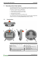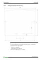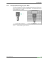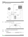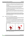
1
KEMRO KeTop T40 User's Manual V2.00 Translation of the original instructions Document : V2.00 / article no.: 61137 Filename : t40_bhen.pdf Pages : 103 . © KEBA 2009 Specifications are subject to change due to further technical developments. Details presented may be subject to correction. All rights reserved. A: KEBA AG, Gewerbepark Urfahr, A-4041 Linz, Tel.: +43 732 7090-0, Fax: +43 732 7309-10, E-Mail: [email protected] D: KEBA GmbH Automation, Leonard-Weiss-Straße 40, D-73037 Göppingen, Tel.: +49 7161 9741-0, Fax: +49 7161 9741-40, E-Mail: [email protected] US: KEBA Corp., 100 West Big Beaver Road, Troy, MI 48084, US, Tel.: +1 248 526-0561, Fax: +1 248 526-0562, E-Mail: [email protected] CN: Beijing Austrian KEBA Science and Technology Development Ltd., Room B516, Nan Xin Cang Tower, A22 Dong Si Shi Tiao, Dong Cheng District, Beijing, 100027, P.R. China, Tel. +86 10 6409-6592, Fax +86 10 6409-6312, E-Mail: [email protected] www.keba.com KeTop T40 Record of Revision Record of Revision Version Date Change in chapter Description changed by V1.70 07-2009 all Insert or adapt requirements (2006/42/EC, EN ISO 13849-1, ZT 05) lb V2.00 08-2009 all Release lb, kreu, mahr User's Manual V2.00 © KEBA 2009 3 Table of Contents Table of Contents 1 Introduction....................................................................................................................... 9 1.1 Purpose of the document........................................................................................ 9 1.2 Target groups, pre-conditions................................................................................. 9 1.3 Intended Use of the Handheld Terminal................................................................. 9 1.4 Notes on this document........................................................................................ 10 1.4.1 Contents of document............................................................................ 10 1.4.2 Not contained in this document.............................................................. 11 1.5 Further documentation.......................................................................................... 11 1.6 Definition of terms................................................................................................. 11 1.7 Information about MD 2006/42/EC........................................................................ 11 1.7.1 Which devices have to comply with the new machine directive?........... 12 1.7.2 Quantitative safety relevant specifications for emergency stopbutton and enabling control device......................................................... 12 1.7.3 Relationship between Performance Level and Safety Integrity Level....................................................................................................... 12 1.7.4 Abbreviations.......................................................................................... 13 2 Safety notes.................................................................................................................... 14 2.1 Representation...................................................................................................... 14 2.2 2.2 General safety instructions.............................................................................. 14 2.3 Personnel safety instructions................................................................................ 16 3 General product description.......................................................................................... 18 3.1 Construction.......................................................................................................... 18 3.2 Ergonomic Features.............................................................................................. 19 3.3 Housing................................................................................................................. 19 3.4 Operating and Display Panel................................................................................ 19 3.5 Hardware............................................................................................................... 19 3.6 Type Plate............................................................................................................. 20 4 Connection...................................................................................................................... 21 4.1 Cable Entrance Area............................................................................................. 21 4.2 Cable Routing in Cable Entrance Area................................................................. 21 4.2.1 Cable outlet left/right.............................................................................. 23 4.3 Power Supply........................................................................................................ 23 4.4 Emergency Stop Button and grey Stop Button..................................................... 24 4.5 Enabling Switch..................................................................................................... 25 4.5.1 Functioning............................................................................................. 25 4.5.2 Example of Connection with PILZ PNOZ s6.1 Control Relay................. 28 4.6 Foreseeable Misuse of Enabling Switch............................................................... 29 4.7 RS-422-A.............................................................................................................. 29 4.7.1 Connection diagram............................................................................... 30 4.7.2 General information about the RS-422-A interface................................ 30 4.8 RS-232-C.............................................................................................................. 30 4.8.1 Connection diagram............................................................................... 31 4.9 Serial port female connector S2 for Debug Interface (RS-232-C)......................... 31 User's Manual V2.00 © KEBA 2009 5 Table of Contents KeTop T40 5 Labelling of Keys............................................................................................................ 32 6 Configuration of KeTop.................................................................................................. 34 6.1 Hardware Required............................................................................................... 34 6.2 KeTop Configuration Software (KeTop PS 040)................................................... 34 6.3 Data Transmission from and to the KeTop........................................................... 34 6.4 Functions of Configuration Software..................................................................... 36 6.4.1 Selection of Protocol.............................................................................. 36 6.4.2 Bitmap Memory...................................................................................... 36 6.4.3 Texts....................................................................................................... 37 6.4.4 Keypad Assignment............................................................................... 40 7 Basic Functions.............................................................................................................. 43 7.1 Power-On Self-Test............................................................................................... 43 7.2 Menu..................................................................................................................... 44 7.2.1 Main Menu.............................................................................................. 45 7.2.2 Diagnosis Menu...................................................................................... 46 7.2.3 Setup Menu............................................................................................ 48 7.2.4 Info Menu............................................................................................... 49 7.2.5 System Reset......................................................................................... 49 7.3 System Errors....................................................................................................... 49 8 Accessories..................................................................................................................... 51 8.1 Wall Bracket without Height Adjustment plate KeTop WB090, WB095, WB120.................................................................................................................. 51 8.1.1 10.1.1 Dimensions (mm)........................................................................ 52 8.2 Wall Bracket with Height Adjustment plate KeTop WB 110.................................. 53 8.2.1 Height adjustment plate.......................................................................... 53 8.3 Junction Box JB 001............................................................................................. 54 8.3.1 Device description.................................................................................. 55 8.3.2 Connection............................................................................................. 56 8.3.3 Connection diagram............................................................................... 56 8.3.4 Shielding inside the Control Cabinet...................................................... 60 8.3.5 Mounting Instructions............................................................................. 61 8.3.6 Technical data of Junction Box JB 001.................................................. 62 8.4 KeTop CB211 Connection Box............................................................................. 62 8.4.1 Construction........................................................................................... 63 8.4.2 Interior view............................................................................................ 64 8.4.3 Technical data of the connection terminals............................................ 64 8.4.4 Drilling template for wall mounting......................................................... 66 8.4.5 DIN Rail Holder Mounting Set KeTop DR200........................................ 67 8.4.6 Use of Connection Box........................................................................... 68 8.4.7 Minimum Bending Radius of Cable........................................................ 68 8.4.8 Technical Data of Connection Box KeTop CB211................................. 68 8.5 Connection Cable KeTop TTxxx........................................................................... 69 8.6 Intermediate Cable KeTop IC2xx.......................................................................... 71 8.7 Download Cable KeTop XD040............................................................................ 72 9 Transport Conditions..................................................................................................... 74 10 12 Disposal of the KeTop............................................................................................... 75 11 Technical Data................................................................................................................ 76 11.1 General data......................................................................................................... 76 6 User's Manual V2.00 © KEBA 2009 Table of Contents 11.2 11.3 11.4 11.5 11.6 11.7 Environmental conditions...................................................................................... 76 Housing................................................................................................................. 76 Processor and interfaces...................................................................................... 77 E-Stop ratings....................................................................................................... 77 Enabling device..................................................................................................... 77 Accessories........................................................................................................... 78 12 CE Conformity, Directives and Standards................................................................... 79 12.1 European Union Directives................................................................................... 79 12.2 Machinery Safety.................................................................................................. 79 12.2.1 "Hazard and Risk Analysis".................................................................... 80 12.2.2 "Principles for the Integration of Safety"................................................. 80 12.2.3 "Technical Construction File"................................................................. 81 12.2.4 "State of the Art"..................................................................................... 82 12.2.5 "Recognition of Conformity by means of Harmonised Standards"......... 82 12.2.6 Selection of Performance Level and Safety Categories in accordance with EN ISO 13849-1.............................................................. 82 12.2.7 Application of Handheld Terminals in Special Operating Modes........... 83 12.2.8 Information about the Emergency Stop Button...................................... 84 12.2.9 Application of Emergency Stop Button and Stop Button on the Handheld Terminal................................................................................. 85 12.2.10 Information about Enabling Devices....................................................... 87 12.3 Electromagnetic Compatibility............................................................................... 89 12.3.1 The electromagnetic environment – interference sources, interference sinks and coupling paths....................................................... 89 12.3.2 EMC measures....................................................................................... 92 12.3.3 EMC measures on KeTop...................................................................... 96 12.4 List of the appropriate EC directives and applied standards............................... 100 12.4.1 EC directives........................................................................................ 100 12.4.2 Standards............................................................................................. 100 13 Conformity and Type Examination............................................................................. 102 13.1 EC Conformity Declaration.................................................................................. 102 13.2 EC Type-Examination Certificate........................................................................ 103 User's Manual V2.00 © KEBA 2009 7 Introduction 1 1.1 Introduction Purpose of the document This document describes the hand-held terminal KeTop T40. This document contains all specifications required by machinery directive 2006/42/EC. 1.2 Target groups, pre-conditions This document is intended for the following persons with corresponding preconditions: Target group Prerequisite knowledge and ability Technical basic education (advanced technical education, engineering degree or corresponding professional experience), Knowledge about: Project engineer ● the method of operation of a PLC, ● safety regulations, ● the application. Technical basic education (advanced technical education, engineering degree or corresponding professional experience), Knowledge about: Start-up technician ● safety regulations, ● the method of operation of the machine or system, ● fundamental functions of the application, ● system analysis and troubleshooting, ● the setting options at the operating devices. Technical basic education (advanced technical education, engineering degree or corresponding professional experience), Knowledge about: Service technician ● the method of operation of a PLC, ● safety regulations, ● the method of operation of the machine or system, ● diagnosis possibilities, ● systematic error analysis and troubleshooting 1.3 Intended Use of the Handheld Terminal The intended use of the Handheld Terminal covers tasks like watching and parametrizing up to operating of machines e.g.: ● Injection moulding machine ● Robots User's Manual V2.00 © KEBA 2009 9 Introduction KeTop T40 ● Machine tools ● Textile machines ● Printing machines ● Theater backdrops ● and similar in normal operating modes ● Automatic as well as ● Setting ● Teaching ● Testing ● and similar in half automatic or manual mode. Enabling switches and an emergency stop button (or halt-button) are the safety elements of the device. The Handheld Terminal is intended for fixed connection to a robot. Handheld Terminals for temporary connection must not have a red-yellow emergency stop button. In this case a handheld terminal with grey halt-button is available. To meet the safety category 3 PL d in accordance with EN ISO 13849-1, the safety functions are realized with 2 circuits. The selection of the Handheld Terminal which is suitable for the machine and the projecting of the additional functions must obey the necessary hazard analyses and risk assessment bounded by law. For intended use of the Handheld Terminal also please pay attention to chapter 12 "CE Conformity, Directives and Standards" on page 79. 1.4 Notes on this document This manual is integral part of the product. It is to be retained over the entire life cycle of the product and should be forwarded to any subsequent owners or users of the product. 1.4.1 Contents of document ● Safety Precautions ● General Instructions ● Connection ● Membran Keypad ● Display ● Software ● Specific Operating Instructions 10 User's Manual V2.00 © KEBA 2009 Introduction ● Options ● Accessories ● Transport Conditions ● Disposal ● Technical Data ● CE Conformity, Directives and Standards 1.4.2 Not contained in this document ● Mask description of the application 1.5 Further documentation Doc.Nr. 1.6 Document name Target group 62010 Serial Gateway Coupling - 61867 Serial MMI-COM Coupling - 61871 Siemens S5 Coupling - 61869 KEBA Standard Protocol - 61907 Serial T-Flex Coupling - Definition of terms This user's manual corresponds to machinery directive 2006/42/EC. The terms used in this manual that come from the machinery directive are the same as in the preceding MD 98/37/EC. Within standard EN 60204-1 the following term has changed: EN 60204-1:1997 Enabling device EN 60204-1:2006 Enabling control device (chapter 10.9) In order to avoid ambiguity for users this manual still uses the term of EN 60204-1:1997. 1.7 Information about MD 2006/42/EC The machine directive (MD) 2006/42/EC will be valid from 2009-12-29 (without any transition period). This means that all machines and safety components that will be brought to market after this date have to confirm this new MD and its harmonised standards. For handheld terminals from KEBA this means that besides the new machine directive also the standard EN ISO 13849-1:2008 will be used. EN ISO 13849-1 demands for the safety relevant component "enabling switch" the specification of category and Performance Level (PL) and for emergency stop-buttons and grey stop-buttons the specification of the B10d-value. User's Manual V2.00 © KEBA 2009 11 Introduction KeTop T40 These values can be found within the manuals in chapter 11.5 "E-Stop ratings" on page 77 and chapter Technical data, Enabling device. 1.7.1 Which devices have to comply with the new machine directive? This rule is valid for KEBA and its customers: Depending on the date the product has been put into circulation the new machine directive has to be applied or not. If the KeTop will be delivered in its end use after 2009-12-29, it will be put into circulation newly - even if it has been sold by KEBA at an earlier date. ● Devices complying with the old MD and that will be sent to KEBA for repair, can be repaired and delivered in compliance with the old MD. ● Customer sends old device for repair and will receive the same or another, equal device. ● Devices complying with the new MD and that will be sent to KEBA for repair, must be repaired and delivered in compliance with the new MD. 1.7.2 Quantitative safety relevant specifications for emergency stop-button and enabling control device ● Emergency stop-button: KEBA specifies a B10d-value. Other values (e.g. SIL, PL, Category) cannot be specified by KEBA. Explanation: KEBA solely delivers the control element, but no evaluation of the element. The customer has to connect the emergency stop to his application on his own. Depending on the connection of the emergency stop to the machine the SIL- or category and PL-value can be determined. ● Enabling control device: KEBA specifies category and PL in accordance to EN ISO 13849-1. Derived from this value KEBA also specifies a PFH- and MTTFd-value in accordance to EN ISO 13849-1. SIL (in accordance to EN 62061 or EN 61508) cannot be specified by KEBA. Explanation: The enabling control devices has been evaluated in accordance to EN ISO 13849-1. A B10d-value is not available for the enabling control device, as this device consists of the mechanic element and the electronic evaluation. This means that KEBA specifies MTTFd- and DCvalues (and derived from these values also Category, PL and PFH) for the enabling control device as a whole (starting from the pushbutton up to the clamps within the junction box). 1.7.3 Relationship between Performance Level and Safety Integrity Level When evaluating safety functions by IEC EN 62601 the PL can be transformed into SIL by following the equivalence table of EN ISO 13849-1. 12 User's Manual V2.00 © KEBA 2009 Introduction Table 4 (EN ISO 13849-1) - Relationship between Performance Level (PL) and Safety Integrity Level (SIL) Performance Level (PL) by EN ISO 13849-1 Safety Integrity Level (SIL) by IEC 61508-1 a no corresponding value b 1 c 1 d 2 e 3 Table 3 (EN ISO 13849-1) - Performance Level (PL) 1.7.4 Performance Level (PL) Average probability of a dangerous breakdown per hour 1/h a ≥ 10-5 to < 10-4 b ≥ 3 x 10⁻⁶ to < 10-5 c ≥ 10-6 to < 3 x 10⁻⁶ d ≥ 10-7 to < 10-6 e ≥ 10-8 to < 10-7 Abbreviations Abbreviation User's Manual V2.00 © KEBA 2009 Term B10d - MTTFd Mean Time to Dangerous Failure DC Diagnostic Coverage PL Performance Level PFH Probability of Failure per Hour SIL Safety Integrity Level 13 Safety notes 2 2.1 KeTop T40 Safety notes Representation At various points in this manual you will see notes and precautionary warnings regarding possible hazards. The symbols used have the following meaning: DANGER! ● indicates an imminently hazardous situation which will result in death or serious bodily injury if the corresponding precautions are not taken. WARNING! ● indicates a potentially hazardous situation which can result in death or serious bodily injury if the corresponding precautions are not taken. CAUTION! ● means that if the corresponding safety measures are not taken, a potentially hazardous situation can occur that may result in property injury or slight bodily injury. CAUTION ● CAUTION used without the safety alert symbol indicates a potentially hazardous situation which, if not avoided, may result in damage to property. ● This symbol reminds you of the possible consequences of touching electrostatically sensitive components. Information Useful practical tips and information on the use of equipment are identified by the “Information” symbol. They do not contain any information that warns about potentially dangerous or harmful functions. 2.2 2.2 General safety instructions The device was developed, manufactured, tested and documented in ac-cordance with the applicable safety standards. If you follow the instructions regarding safety and use as described in this manual (see chapter 1.3 "Intended Use of the Handheld Terminal" on page 9), the product will, in the normal case, neither cause personal injury nor damage to machinery and equipment. The instructions contained in this manual must be precisely followed in all circumstances. Failure to do so could result in the creation of potential sources of danger or the disabling of safety features integrated in the handheld terminal. 14 User's Manual V2.00 © KEBA 2009 Safety notes Apart from the safety instructions given in this manual, the safety precautions and accident prevention measures appropriate to the situation in question must also be observed. Handling of KeTop You have chosen a high-quality KeTop that is equipped with highly sensitive state-of-the-art electronics. To avoid malfunctions or damage through improper handling, follow these instructions during operation. WARNING! The following application areas are expressly excluded for the KeTop: ● Use in areas prone to explosion or fire ● Use in mining ● Outdoor use Other products must be used for these applications! The KeTop housing must not be opened (acception: cable entrance area) , as the KeTop is sensitive to electrostatic discharge. User's Manual V2.00 © KEBA 2009 15 Safety notes KeTop T40 CAUTION 2.3 ● Turn off the power supply before opening the cable entrance area of the KeTop. Otherwise the components could be destroyed or undefined signals could occur. ● Make sure that nobody can fall over the cable to avoid that the device falls to ground. ● Take care not to squeeze and thus damage the cable with any object. ● Do not lay the cable over sharp edges to avoid damaging the cable sheath. ● If you do not use the device, hang it into the wall bracket KeTop WBxxx provided for storage. ● Do not lay down the device with the operating side facing down to avoid damaging the operating elements. ● Never lay the device onto unstable surfaces. It could fall to ground and thus be damaged. ● Never lay the device close to heat sources or into direct sunlight. ● Avoid exposing the device to mechanical vibrations, excessive dust, humidity or to strong magnetic fields. ● Never clean the device, operating panel and operating elements with solvents, scouring agent or scrubbing sponges. For cleaning the device, use a soft cloth and a bit of water or a mild cleaning agent. ● Make sure that no foreign objects or liquids can penetrate into the device. Check at regular intervals the protective covers of the device, if all housing screws are firmly tightened and if the housing or the cable entry is damaged. ● If the device shows any defect, please send it, including a detailed error description, to your supplier or the relevant after-sales service office. ● If the KeTop is equipped with a touch screen, then operate the touch screen with fingers or use a touch-pen. Never use sharp objects (e.g. screwdriver,...) for operating the touch screen. This could damage the touch screen. Personnel safety instructions WARNING! Danger to persons by electric shock! ● Only supply the device with power from voltage sources having protective extra-low voltage (e.g. SELV or PELV acc. to IEC 61131-2) ● Only connect voltages and circuits which are safely separated from dangerous voltages (e.g. by means of sufficient insulation) to connections, terminals or interfaces up to a rated voltage of 50 V. CAUTION! Danger of fire in case of component failure! ● 16 In final application, make sure the 24 V DC power supply to the operator panel is adequately fused! Max. permissible fuse is 3.15 A! User's Manual V2.00 © KEBA 2009 Safety notes WARNING! ● For the right projecting of the Handheld Terminal the manufactorer must enforce a hazard and risk analysis. The following safety aspects must be considered: - Right cable length for limitation of workspace. - Is an emergency stop button necessary and permissible? - Is the safety category for the application sufficient? User's Manual V2.00 © KEBA 2009 ● From the operating place the operator must have a good view at the hazard area. ● The device may be operated in faultless condition only and the operating instructions must be observed. ● The operator must have a sufficient educational level and must know details of intended use described in the user’s manual. ● The safety advices in the following chapters must be considered absolutely. ● Further informations to safety and EMC are included in chapt. "CE Conformity, Directives and Standards". They must be considered absolutely. 17 General product description 3 KeTop T40 General product description The handheld terminal KeTop T40 is a portable operating and display device made for industrial use. With its rugged design and its optimised ergonomics it is ideal for a great variety of applications: ● Operator panel for machines and plants ● Teach and programming panel for robots ● Start-up device for drives ● Handheld operating device for machine tools The configuration of the KeTop T40 is performed by means of the configuration software included in the KeTop Startkit T40(available at KEBA). 3.1 Construction Fig.3-1: Construction of KeTop T40 1 ... Emergency stop switch with mechanical protection 3 ... Error-LED (red) 5 ... Detachable cover for insertable labels 7 ... Strain relief for connection cable (delivered with the connection cable) 18 2 ... STN LC display with 128x64 pixels (20 columns, 8 lines) 4 ... 32 keys with tactile feedback and a green LED per key 6 ... 8 insertable labels for individual labeling (below label cover) 8 ... Run LED (green) User's Manual V2.00 © KEBA 2009 General product description 9 ... Two 3-position enabling switches (left and right), twin circuit 11... Cable entrance area (lid) 3.2 10... Multigrip handle 12... Blind plug for cable outlet not used (to guarantee the degree of protection IP65) Ergonomic Features ● Multigrip handle ● Round housing ● Different holding positions ● Operation by right-handed and left-handed people ● Desk top operation ● Operation in wall bracket ● The cable outlet can be on the left or right side of the housing. ● Easy-to-read display 3.3 Housing ● Vibration- and shock resistance ● Housing made of non-flammable material (UL 94-V0), impact-resistant, withstands water, cleaning agents (alcohol and tensides), oil, drilling oils, grease and lubricants ● Twin shell, extremely sturdy housing. Drop-tested on industrial flooring from a height of 1.5 m (59 in). 3.4 Operating and Display Panel ● Membrane keys with tactile feedback ● 2 status LEDs ● Buzzer in upper part of housing ● one LED per key for user guidance ● Backlit STN LC display with 128x64 pixels (20 columns, 8 lines) 3.5 Hardware ● CPU Hitachi H8/2144 ● Memory: 1 MB Flash, 128 kB SRAM ● Interface: RS-422-A and RS-232-C (Debug) User's Manual V2.00 © KEBA 2009 19 General product description 3.6 KeTop T40 Type Plate Sample of a KEBA type plate of the KeTop product family: Fig.3-2: 1 ... 3 ... 5 ... 7 ... 9 ... 11... 13... 15... 17... 20 Sample type plate of the KeTop product family Manufacturer Material name Technical data (here: power supply) Serial number Date of production (month/year) UL marking (optional) BG marking (optional) CE marking Revision number of device 2 ... 4 ... 6 ... 8 ... 10... 12... 14... 16... 18... Manufacturer's address Further information (optional) Bar code SIBE marking (optional) Ambient temperature ROHS marking Advice for electronic scrap regulation ÖVE marking (optional) Material number User's Manual V2.00 © KEBA 2009 Connection 4 4.1 Connection Cable Entrance Area Fig.4-1: 4.2 Cable entrance area of KeTop T40 Cable Routing in Cable Entrance Area After opening the cable entrance area, the connecting lines can be routed as described in the following chapters. Before opening the KeTop please pay attention to the following safety instructions: User's Manual V2.00 © KEBA 2009 21 Connection KeTop T40 Information Instructions for opening the cable entrance area: ● Lay the KeTop with the display facing down onto a plane and clean table (preferable on ESD pad) and take care not to damage the KeTop and its operating elements. ● For opening and closing the cable entrance area use the following type of screwdriver: "Phillips size 2". Instructions for modifications in the cable entrance area: ● Unplug the main connector (S19) by pulling on its wires with your fingers. Do not use any sharp objects. ● For unplugging the RJ-45 jack (S6), actuate the locking lever: Fig.4-2: Uplugging main connector (S19) and RJ-45 jack (S6) 1 ... main connector 2 ... RJ-45 jack WARNING! ● Make shure that the main connectors (S19) and the RJ-45 jack (S6) correctly snap in when you plug them in. Otherwise the emergency stop functionality (S19) or the correct shielding (S6) might not be given any more. ● Validate the emergency stop-functionality before re-starting the KeTop. Information Instructions for closing the cable entrance area: Make sure that ● the sealing is clean, not damaged and correctly positioned in the cable entrance area, ● no cables are squeezed in, ● the cover of the cable entrance area is attached again with all 6 screws (torque: 0.4 bis 0.5 Nm). Otherwise the protection degree cannot be guaranteed. 22 User's Manual V2.00 © KEBA 2009 Connection 4.2.1 Cable outlet left/right Fig.4-3: 4.3 Cable outlet on left and right side with data and control lines Power Supply WARNING! The device meets the safety class III in accordance with EN61131-2. The 24V power supply for the equipment must be guaranteed through safe isolation of the low-voltage circuits from dangerous-contact voltage circuits (e.g. by safety transformers or similar facilities). WARNING! The power supply circuit must be protected with a 3.15 A fuse. Information When planning the power supply, take into account the voltage drop on the KeTop TTxxx connection cable! Specification of power supply lines in the KeTop TTxxx connection cable: ● Cross section: AWG24 (0.24mm²) ● Material: zinc-coated copper strand ● Line resistance: ≤ 90 Ohm/km (≤ 145 Ohm/mile) The nominal supply voltage directly on the handheld terminal (without KeTop TTxxx connection cable) is: +24 V DC (fully operational in the range 18 V DC - 32 V DC). Maximum interruption time of supply voltage: ≤ 10 ms (according to IEC 61131) Power consumption: 4.32 W (240 mA at 18 V DC, 180 mAat 24 V DC) User's Manual V2.00 © KEBA 2009 23 Connection 4.4 KeTop T40 Emergency Stop Button and grey Stop Button The emergency stop button respectively the grey stop button used on the KeTop features two circuits. The contacts are normally closed. The red-yellow emergency stop button of the handheld terminal meets the requirements of the EN ISO 13850. It must be designed as an emergency stop of category 0 or category 1 (see EN 60204-1 chapter 9.2.5.4.2) on the basis of the risk assessment for the machine. The connection of the positive-break contacts to an appropriate monitoring system must meet the safety category (in accordance with EN ISO 13849-1) which is defined by means of the risk assessment (in accordance with EN ISO 14121-1) of the machine. Optionally the KeTop is also available with a grey stop button instead of the red-yellow emergency stop button. In principal the grey stop button has the same functionality as the red-yellow emergency stop button. If the handheld terminal is not plugged in, the grey color of the stop button should avoid the usage of the non-effective (emergency) stop button in dangerous situations. The grey stop button fulfils also all mechanical aspects of the EN ISO 13850 and differs from the emergency stop button only by its color. WARNING! ● Not fully functional emergency stop devices may have fatal consequences! Emergency stop switches which are red-yellow marked must be effective under all circumstances in all operating modes of a machine or plant. Store handheld terminals with not operational red-yellow emergency stop switches on a place where the operator cannot see it, so that he can not mistake the device. Handheld terminals which are plugged in and out frequently for temporarely use, must not have a red-yellow emergency stop switch. Such devices must be equipped with a grey stop switch. ● Resetting an activated emergency stop facility must not result in uncontrolled start-up of machines or installations. ● The emergency stop button does not replace other safety facilities. ● The emergency stop button on the handheld terminal does not replace the emergency stop buttones to be mounted directly on the machine. ● Some mechanical errors in emergency stop switches can be recognized at operation only. Test the function of the emergency stop switch when the device had been exposed to mechanical shock (e.g. it had been fallen on the ground). Additionally the emergency stop switch must be tested cyclic (6 monthly). Watch the machine stopping after the emergency stop switch had been pushed. ● 24 For further informations to emergency stop switch observe chapter 12 "CE Conformity, Directives and Standards" on page 79. User's Manual V2.00 © KEBA 2009 Connection 4.5 Enabling Switch The KeTop is equipped with two enabling switches, one at the left and one at the right side of the device. This allows a left- and right-hand operation of the enabling switch. Both enabling switches are equivalent and parallel switched. So for enabling only one of both enabling switches must be activated. The enabling switch consists of a 3-position operating element and an separated evaluation electronics. An essential feature are the continuous twochannel circuits beginning from the actuating elements up to the connecting terminals. For the evaluation circuits different technologies and circuits are used. Due to the electronic switching contacts, their lifetime does not depend on the load provided the nominal values of the load (ohmic, inductive and capacitive) are not exceeded. The switching elements of the enabling switches are protected against reversed polarity. The outputs of both circuits are protected against short circuits and overload. Circuit 1: thermal protective circuit Circuit 2: fold back line 4.5.1 Functioning The actuating element consists of two symmetrically arranged slides. The position of these slides is detected by electrical switches and transmitted to the evaluation electronics. Positions of enabling switch: Position Function Enabling switch Contacts 1 home position is not pressed enabling outputs are open 2 enabling is pressed enabling outputs are closed 3 panic is pressed strong enabling outputs are open Tab.4-4: Positions of the enabling switch WARNING! The enabling switch must be tested cyclic (6 monthly) by pressing the panic position. Watch the machine performing the panic function after pressing the enabling switch. User's Manual V2.00 © KEBA 2009 25 Connection 4.5.1.1 KeTop T40 Enabling Fig.4-5: 4.5.1.2 Contact travel diagram for enabling Panic The pushing of the actuating elements into the panic position is evaluated in a way that the enabling position is skipped when the actuating elements are released. Fig.4-6: Contact travel diagram for panic Information At the KeTop, the enabling switches always feature two circuits. To meet the safety category 3 PL d in accordance with EN ISO 13849-1, the enabling switch must be realized with 2 circuits and these circuits have to be monitored on short circuits. The safety category 3 PL d means, that one failure must not lead to the loss of the safety function, and whenever possible, the single failure is detected. 26 User's Manual V2.00 © KEBA 2009 Connection The example of connection in chapter 4.5.2 "Example of Connection with PILZ PNOZ s6.1 Control Relay" on page 28 shows how the safety category 3 PL d can be fulfilled by the enabling switch up to the output terminal K4 within the connection box. The entire concept of the machine must be laid out according to the principles of safety category 3 PL d. The monitoring of the simultaneity by the control relay is necessary, because otherwise maybe a failure culmination would not be recognised and this would cause the loss of safeness: Example: If one circuit of the enabling device switches to the enabled state as a result of a failure and after some time the second circuit also switches to the enabled state as a result of an failure, then no de-energisation by the enabling device would be possible. Further the EN 60204-1 prescribes that the enabling switches shall be connected to a category 0 stop or a category 1 stop, that means the energy must be switched off. For calculation of the PL for the safety function "enabling" the PL- and B10dvalues of all involved components have to be included. For details for calculating the PL for the whole safety function see EN ISO 13849-1, chapter 6.3, appendix H and appendix I. User's Manual V2.00 © KEBA 2009 27 Connection 4.5.2 KeTop T40 Example of Connection with PILZ PNOZ s6.1 Control Relay Fig.4-7: 4.5.2.1 Suggested wiring of enabling swithches to fulfill safety category 3 PL d for the enabling switch with PILZ control relay. Also follow the instructions described in the PILZ operating manual about the device PNOZ s6.1. For calculation of the whole safety function "enabling" the control relay and all subsequent components have to be considered. Functional procedure ● Only if both channels are activated "simultaneously (≤0,5s)" (by pressing one of the enabling switches) both output relays K1 and K2 will energize and the output contacts 13-14 and 23-24 will close. ● The output relays K1 and K2 will not energize if ● only one enabling channel is activated (in case of a defect), 28 User's Manual V2.00 © KEBA 2009 Connection ● the tolerance value for the simultaneity period is exceeded, ● the feedback control loop S34 is open. ● If one enabling channel is deactivated after being simultaneously activated (by releasing the enabling switch or in case of a defect), the output relays K1 and K2 will return to their initial position again. The forced-guided output contacts 13-14 and 23-24 will open. The output relays will energize again only after both enabling channels have been deactivated and simultaneously activated once again. In this way the enabling switches avoid that one single error makes the safety function inoperational. A single error will be recognized at the next cycle at the latest, identifying that re-enabling is no longer possible. In case of short circuit the control relay switches to ERROR and has to be turned OFF and ON again after resolving the error. 4.6 Foreseeable Misuse of Enabling Switch Foreseeable misuse means the not allowed fixing of the enabling switch in the enabling position. The foreseeable misuse of the enabling switch must be restricted. The following measures causing the stop of the machine in the manual mode are recommended: ● Inquiry of the enabling switch when turning on the machine/plant and inquiry of the enabling switch when changing the operating mode from automatic to manual (The enabling switch must not be in the enabling position.). ● The enabling switch must be released within a defined period and pushed into the enabling position again. The length of the period must be defined according to the activity. WARNING! 4.7 ● The enabling switch is only suitable as safety function if the operator activating the enabling switch recognizes the dangerous situation in time so that he can immediately take the necessary measures to avoid such situations. As additional measure reduced speed of the movement can be necessary. The allowed speed must be determined by means of a risk assessment. ● The enabling switch is only used to enable commands for performing dangerous movements. The commands themselves must be activated by a separate operating element (key on handheld terminal). ● Only the person who operates the enabling switch is allowed to work in the dangerous area. ● For further informations regarding the enabling switch please pay attention to chapter 12 "CE Conformity, Directives and Standards" on page 79. RS-422-A The communication takes place via the COM module connector S6 in the cable entrance area of the KeTop. User's Manual V2.00 © KEBA 2009 29 Connection KeTop T40 The RS-422-A interface assigned to the COM 5 interface port is in the software. The interface parameters are set via the WIN32API in the Windows operating system. 4.7.1 Connection diagram Fig.4-8: 4.7.2 Connection diagram: KeTop with RS-422-A via connection box CB211 General information about the RS-422-A interface ● The A terminal of the generator shall be negative with respect to the B terminal for a binary 1 (MARK or OFF) state. ● The A terminal of the generator shall be positive with respect to the B terminal for a binary 0 (SPACE or ON) state. To identify the lines, the voltage between the lines A and B can be measured by means of a voltameter. 4.8 RS-232-C The communication takes place via the COM module connector S6 in the cable entrance area of the KeTop. The RS-422-A interface assigned to the COM 2 interface port is in the software. 30 User's Manual V2.00 © KEBA 2009 Connection 4.8.1 Connection diagram Fig.4-9: 4.9 AConnection diagram: KeTop with RS-232-C via connection box CB211 Serial port female connector S2 for Debug Interface (RS-232-C) This interface will be used for programming the KeTop T40by the programming software KeTop PS040. For that purpose, the download cable KeTop XD040 is available. The following interface parameters are defined and cannot be changed: ● 8 data bits ● 1 stop bit ● no parity ● no handshake The debug interface is assigned to the COM 1 interface port in the software. User's Manual V2.00 © KEBA 2009 31 Labelling of Keys 5 KeTop T40 Labelling of Keys Since different functions can be assigned to the keys of the KETOP, you have the possibility to label the operator panel according to your specific requirements. Drawing foils or paper strips are suitable for that purpose. The desired symbols are drawn onto the visible fields. Information ● Paper labels: We recommend using paper with a size of 115 g/m². ● Foil labels: We recommend using the following products by Folex: X-350 wo (white opaque) suitable for color copier 100 µm X-360 wo (white opaque) suitable for color copier 125 µm BG 32 wo (white opaque) suitable for ink jet printer 100 µm Fig.5-1: Inserting of a paper label TIP: To facilitate the inserting of the label, insert also a foil (e.g. company logo) below the label step by step. Once the label is completely inserted, remove the foil. When removing the foil, press on the membrane keyboard to avoid that the label is removed as well. 32 User's Manual V2.00 © KEBA 2009 Labelling of Keys Fig.5-2: User's Manual V2.00 © KEBA 2009 Dimensions of labels in mm 33 Configuration of KeTop 6 KeTop T40 Configuration of KeTop For setting the configuration of the device and for generating texts and the keypad layout, a configuration software executable under MS-Windows (95, NT, 2000, XP) is supplied. This software provides functions for creating configuration data, editing text lines and the keyboard layout and loading the program. The operation of the software is menu-driven. 6.1 Hardware Required For creating the device configuration, the following hardware components are required: ● KeTop T40 ● Configuration PC with KeTop configuration software (KeTop PS 040) ● 24V DC power supply unit for the KeTop ● Download cable KeTop XD 040 (connection cable between the serial port connector S2 in the cable entrance area of the KeTop and a free serial interface (COM1, COM2,...) on the configuration PC) For connecting the KeTop, the connection box KeTop CB 211 can be used alternately. 6.2 KeTop Configuration Software (KeTop PS 040) The configuration software under Windows is supplied on a CD. Installation: ● Insert the CD into your configuration PC and invoke the automatic installation program SETUP.EXE under Windows. 6.3 Data Transmission from and to the KeTop The configuration software provides several functions for transmitting data from or to the KeTop. Data transmission from or to the KeTop is only possible in the loading mode "Program loader ready". For that purpose, hold the following keys pressed when turning on the KeTop until "Program loader ready" appears on the display: 34 User's Manual V2.00 © KEBA 2009 Configuration of KeTop Fig.6-1: Key combination (when turning on the KeTop) for the access to the loading mode "Program loader ready" The following mask is displayed: Fig.6-2: t v x z ... ... ... ... Mask in loading mode "Program loader ready" version of boot software interface type (RS-232-C, 20 mA CL) parity stop bit u ... number of interface port (1 or 2) w ... baudrate y ... data bits The KeTop is in the loading mode now, and the data transmission can be activated via the configuration software. Depending on the transmission direction, the following data are displayed: Fig.6-3: Mask during data transmission t ... version of boot software * ... down(load): PC -> KeTop or up(load): PC <- KeTop x ... rotating bar during transmission or OK when the transmission has been completed successfully. Once the data have been transmitted successfully to the KeTop, the device performs a reset and starts the cyclic execution of the user program. User's Manual V2.00 © KEBA 2009 35 Configuration of KeTop 6.4 6.4.1 KeTop T40 Functions of Configuration Software Selection of Protocol Before starting the configuration, the requested coupling must be selected. The following protocols are available: ● Serial KEBA standard protocol This protocol is used for serial communication. See User's Manual "KeTop T40 KEBA Standard Protocol". ● Serial Gateway MMI-COM This protocol is used for the connection to serveral bus systems via the gateway boxes KeTop CB23x. See User's Manual "KeTop T40 Serial Gateway MMI-COM Coupling". ● Serial MMI-COM This protocol is used for serial communication. See User's Manual "KeTop T40 Serial MMI-COM Coupling". ● Serial S5 CP (RK512) For the connection to Siemens S5 communication processors. See User's Manual "KeTop T40 Siemens S5 Coupling". ● Serial S7 CP (RK512) For the connection to Siemens S7 communication processors and for the connection via Gatewaybox KeTop CB236. See User's Manual "KeTop T40 Siemens S5 Coupling". ● Serial S5 PG (AS511) For the connection to Siemens S5 central processors via the programmer port. See User's Manual "KeTop T40 Siemens S5 Coupling". ● Serial NAIS FP1 PG (Matsushita) ● Serial T-Flex See User's Manual "KeTop T40 T-Flex Coupling". 6.4.2 Bitmap Memory Up to 1000 bitmaps can be stored in the bitmap memory of the KeTop. These bitmaps can displayed by a simple PLC command. For displaying the bitmaps, take into account the following points: ● Maximum memory for the 1000 bitmaps: 320 kB Bitmaps filling the entire display (128 x 64 pixels) require a memory of approx. 1 kB. If only bitmaps of this size are used, it will not be possible to store 1000 bitmaps in the memory since the maximum storage capacity of 320 kB is exceeded. ● Only uncompressed, 2-color (b/w) Windows bitmaps may be used. 36 User's Manual V2.00 © KEBA 2009 Configuration of KeTop 6.4.3 Texts Depending on the number of configured variable fields, up to 8143 texts with a length of one line each can be defined. These texts are stored in the KeTop and can later be displayed by means of a simple PLC command. Fig.6-4: 6.4.3.1 Text call from text memory Configuring Variables in a Text It is possible to configure several variables in a text line. The positions of the variables must be identified by specific characters for input or output fields: Field type I/O type of variable Characters for fields Representation on KeTop display (without numerical value) Output field "OUT" '#', '@' * Blank Input field "IN" '_', '~' * '_' Input/output field "IN/OUT" '_', '~' * '_' * ... These alternative characters enable placing one variable field after the other (e.g. # # # @ @ @ # # # or _ _ ~~ # #). During operation, the numerical values are displayed in the variable fields. If the value of the variable is too long so that it cannot be displayed in the programmed field ‘*’ characters will be displayed (e.g. 2-digit output field: ##, value to be displayed: 100, => output: ‘**’). Variables may be configured with a maximum of 7 decimal places. 6.4.3.2 Defining Variables For input and output fields in a text line, the corresponding variable must be defined by a variable number, a data type, the format and the I/O type. Variable number The value range depends on the type of coupling and is described in the corresponding user's manual. For the "KEBA Standard Protocol" and for the "Serial MMI-COM Coupling" the value to be entered must range between 100-65535 (exception STRING variable: 0-255). User's Manual V2.00 © KEBA 2009 37 Configuration of KeTop KeTop T40 Data word Data words must only be specified at Siemens and NAIS couplings. The data word contains the PLC variable and corresponds to the input field "Variable number" at other couplings. Data type Selection possibilities: Data type Length Value range UINT8 1 byte 0...255 SINT8 1 byte -128...+127 UINT16 2 bytes 0...65535 SINT16 2 bytes -32768...+32767 UINT32 4 bytes 0...4294967295 SINT32 4 bytes -2147483648...+2147483647 FLOAT32 4 bytes -3.4*10-38...+3.4*1038 STRING n bytes - Format Selection possibilities: Format Description DEC decimal (0...9) HEX hexadecimal (0...9, A...F) BIN binary (0, 1) BCD "Binary Coded Decimal" (0...9) INVISIBLE Entry of passwords. Each character entered is displayed as '*' (possible with I/O type "IN" and data type "STRING" only). TEXT The variable format "TEXT" enables calling a text from the internal text memory via variables. Depending on the text number, the data typeThe variable format "TEXT" enables calling a text from the internal text memory via variables. Depending on the text number, the data type UINT8, UINT16 or UINT32 must be used (only allowed with I/O type "OUT"). If the data type "STRING" is used the contents of the variable will be displayed/read in on the KeTop as ASCII character string and transmitted to the control after pressing the Enter key. 6.4.3.3 I/O type OUT = output. The variable is read from the PLC or written by the PLC and displayed in the corresponding variable format. The output field must be identified by the character '#'. 38 User's Manual V2.00 © KEBA 2009 Configuration of KeTop IN IN = input. An empty input field is displayed. Pressed keys appear on the display one after the other. After pressing Enter, the key string entered is evaluated and transmitted to the PLC. Pressing the "Esc" key cancels the editing process, and the value in the PLC remains unchanged. The input field must be identified by the character '_'. IN/OUT = combination of input and output. The variable can be written by the PLC, but also entered on the KeTop and transmitted to the PLC. Pressing Enter completes the editing process, and the value entered is transmitted to the PLC. Pressing the "Esc" key cancels the editing process, and the value in the PLC remains unchanged. The field for the I/O type "IN/OUT" must be identified by the character '_'. Fig.6-5: Display of text in an output field for variables Examples of output fields for variables Output field for variables ## Data type Format I/O type UINT8 DEC OUT UINT16 DEC OUT ##.## SINT16 User's Manual V2.00 © KEBA 2009 DEC OUT Value of variable (decimal) Display 99 '99' 100 ' 1.00' 5 ' 0.05' -1 '-0.01' 39 Configuration of KeTop KeTop T40 FLOAT32 ##### ######## #### 6.4.4 FLOAT32 UINT8 UINT16 DEC DEC BIN HEX 1.234 ' 1.23' 100.1 '**.**' -1.5 ' -1.5' 43.78 '43.78' 32 00100000 85 01010101 31548 '7B3C' 45054 'AFFE' OUT OUT OUT OUT Keypad Assignment One, two, three or four codes may be assigned to each key. Following the functionality of a PC keyboard, one of the 32 keys must be assigned as "Shift" key in case of a double assignment. In case of a triple assignment, an additional "Ctrl" key must be defined. If 4 codes are assigned to one key, an additional "Alt" key is required. 6.4.4.1 Configurable Keys The keys with characters specified in chapter 6.4.4.3 "Display Character Set" on page 41 and the following special keys can be configured: ● Shift Selects a character of the 2nd keypad layout level (pressing Shift and the corresponding key simultaneously). ● Shift Lock Switches over to the 2nd keypad layout level and remains activated until the Lock key is pressed once again or another Lock key (Ctrl Lock, Alt Lock) is pressed. ● Control Selects a character of the 3rd keypad layout level (pressing Ctrl and the corresponding key simultaneously). ● Control Lock Switches over to the 3rd keypad layout level and remains activated until the Lock key is pressed once again or another Lock key (Shift Lock, Alt Lock) is pressed. ● Alt Selects a character of the 4th keypad layout level (pressing Alt and the corresponding key simultaneously). ● Alt Lock Switches over to the 4th keypad layout level and remains activated until the Lock key is pressed once again or another Lock key (Shift Lock, Ctrl Lock). ● Enter Takes over a variable entered (following that, the cursor jumps to the next input field). The value is sent to the PLC. 40 User's Manual V2.00 © KEBA 2009 Configuration of KeTop ● ESC Deletes the current input. The old contents of the field (before the input) are displayed again (cursor remains in current input field). ● Delete Deletes a character. ● ←, →, ↑, ↓ Cursor control in case several input fields are available. 6.4.4.2 Examples of Function of Variable Editor in the KeTop Example 1: Example 2: Example 3: Example 4: Example 5: Password entry (data type: STRING, format: INVISIBLE) 6.4.4.3 Display Character Set The following list shows the ASCII characters which can be displayed on the handheld terminal. User's Manual V2.00 © KEBA 2009 41 Configuration of KeTop Fig.6-6: 42 KeTop T40 Character set that can be displayed on KeTop T40 User's Manual V2.00 © KEBA 2009 Basic Functions 7 7.1 Basic Functions Power-On Self-Test The KeTop performs a power-on self-test. The safety functions are not tested in this case. If no error occurs the test steps (marked by bullets) will be carried out one after the other in brief sequences. ● The internal signal buzzer of the KeTop triggers a short audible signal. ● The program is checked. Normally the following message is displayed: x ... version of boot software The message will be displayed for 2 s if an error has been recognized in the program or if the program is not available in the KeTop. Then the device changes to the loading mode (the display indicates "Program Loader ready"). See also chapter 6.3 "Data Transmission from and to the KeTop" on page 34). The following messages are only displayed in case of errors: ● The ROM contents are checked. The message will be displayed if a ROM error has been recognized. The device remains in this error condition. A new start is only possible after turning off and on the device. ● The FLASH type is checked. The message User's Manual V2.00 © KEBA 2009 43 Basic Functions KeTop T40 y ... 1 or 2 will be displayed if an unkown FLASH type is entered in the configuration data. The device remains in this error condition. A new start is only possible after turning off and on the device. ● The configuration data checksum is checked. The message y ... 1 or 2 will be displayed for approx. 2 s if the checksum is not correct. The device changes to the "Configuration Loader" mode. A new start is only possible after turning off and on the device. ● The keypad matrix for pressed keys is checked. The message will be displayed if one or more pressed keys have been found during testing. The device remains in this condition as long as the keys remain pressed. After the keys are released, the KeTop continues performing the self-test. ● After the flash memory test, the system program is invoked. What will be displayed further depends on the program. 7.2 Menu To access the main menu, press the keys 1 and 2 after turning on the KeTop and the application. "MAIN MENU" appears in the first line of the display. After you release the keys, the menu itself will be displayed. 44 User's Manual V2.00 © KEBA 2009 Basic Functions Fig.7-1: Key combination (when application is already running) for access to "Main Menu" Information The access to the main menu can also be deactivated if required. For details about the deactivation, please refer to the manual dealing with the specific coupling. For the following menus, the keys of the first row are available as softkeys. The last line of the display shows what functions are assigned to the keys of the first row. Fig.7-2: Assignment of softkeys to keys In all menus, the key 11 is the ESC key. Apart from few exceptions, the keys 12, 13 are used to move up and down the brackets "> <" that identify the function to be selected. The key 14 (OK) is used to confirm the selection. 7.2.1 Main Menu The main menu provides the following functions: MAIN MENU Diagnosis Setup Info System Reset User's Manual V2.00 © KEBA 2009 45 Basic Functions 7.2.2 KeTop T40 Diagnosis Menu The diagnosis menu is a submenu of the main menu and provides different test functions: DIAGNOSIS MENU Keyboard Test Buzzer Test Enabling Swi. Test COM Test LED Test Display Software 7.2.2.1 Keyboard Test Tests the keypad of the KeTop. All keys pressed from 2 to 32 are displayed one after the other in the line "Pressed Key:". The key 11 is the ESC key. 7.2.2.2 Buzzer Test The buzzer remains turned on until you quit the menu by pressing ESC. 7.2.2.3 Enabling Switch Test The state of the enabling switch will be displayed: If the enabling switch is in the "home position" or "enabling position", the following message appears on the display: If the enabling switch is in the "panic position" (enabling switch completely pressed), the following message appears on the display: 7.2.2.4 COM Test All interfaces available in the KeTop can be selected for testing. They can be tested without being connected to the PLC: 46 User's Manual V2.00 © KEBA 2009 Basic Functions COM Test COM1:RS232 COM2:RS232/RS422 At the interface to be tested, the transmitter and the receiver must be linked together (e.g. directly at the connectors in the cable entrance area or onsite at the end of the signal lines). The terminal and signal designations of the following drawings refer to the connectors in the cable entrance area: User's Manual V2.00 © KEBA 2009 Fig.7-3: Interface test: COM 1, RS-232-C (debug interface) Fig.7-4: Interface test: COM 2, RS-422-A Fig.7-5: Interface test: COM 2, RS-232-C 47 Basic Functions KeTop T40 The interface test is performed on the basis of the interface parameters set during programming. Factory-set interface parameters (the interface parameters can also be checked in the menu "Info -> COM-Parameter"): 9600 Baud, no parity, 8 databits, 1 stopbit. During the interface test, the selected interface appears on the display: x ... interface 1 or 2 y ... interface type (RS232 or RSxx2 for RS232 I RS422) ● Transmit The KeTop sends the ASCII characters "0" (30H) to "z" (7AH) one after the other at intervals of one second. The characters sent are displayed at the position a. ● Receive The characters just sent are received one after the other and displayed at the position b. If the send/receive line or the interface is defective, nothing will be displayed. 7.2.2.5 LED Test The LEDs are flashing at one second intervals. The corresponding status is displayed 7.2.2.6 Display Display of all characters which can be displayed. 7.2.2.7 Software Certain warnings are logged for diagnostic purposes and assist KEBA's service engineer in analysing errors. Normally the display indicates the message "No warnings!". The entries in this message storage are only for information. Most warnings refer to handling errors caused by the user. 7.2.3 Setup Menu The setup menu is a submenu of the main menu and provides the following functions: SETUP MENU Program Loader Parameter 48 User's Manual V2.00 © KEBA 2009 Basic Functions 7.2.3.1 Program Loader This function is used to set the parameters of the interface via which the program is loaded from the PC into the KeTop. These parameters are only relevant during the loading process. This menu item does not start the loading process. To switch the KeTop over to the loading mode, press and hold the keys 1 and 2 simultaneously when turning on the KeTop until the message "Program loader ready" appears on the display. 7.2.3.2 Parameter No setting values at present. 7.2.4 Info Menu The info menu is a submenu of the main menu and provides the following functions: INFO MENU Hardware Software COM-Parameter 7.2.4.1 Hardware Important data of the device hardware are displayed. 7.2.4.2 Software Version of software is displayed. 7.2.4.3 COM-Parameter Set interface parameters. 7.2.5 System Reset The menu item "System Reset" included in the main menu restarts the KeTop. This process corresponds to a turning on and off of the device. Pressing the two keys 1 and 2 switches the device to the loading mode. 7.3 System Errors Fatal system errors can be caused by a defective hardware or an error in the system software (no handling error). In case a fatal error occurs the following will be displayed: User's Manual V2.00 © KEBA 2009 49 Basic Functions KeTop T40 a ... c ... f ... Time... component number module name task name time between turning on of device and occurrence of error (in days, hours, minutes, seconds and milliseconds) b ... error number e ... line number in source code g ... additional information Information ● Since fatal errors are not stored in the device, please note the complete text displayed and contact a service engineer from KEBA. ● If a system error occurs in the KeTop, the KeTop will no longer respond to incoming packets. To correct this error, turn the KeTop off and then on again. 50 User's Manual V2.00 © KEBA 2009 Accessories 8 8.1 Accessories Wall Bracket without Height Adjustment plate KeTop WB090, WB095, WB120 The powder-coated black wall bracket is used for stationary operation or storage of the KeTop. Three types of wall brackets without height adjustment plate are available: KeTop WB090 Wall bracket without cable suspension Fig.8-1: © KEBA 2009 KeTop WB120 Wall brackets KeTop WB090, WB095 and WB120 1 ... Carrier 3 ... solenoids User's Manual V2.00 KeTop WB095 Wall bracket with cable sus- Wall bracket with cable suspenpension sion and solenoids 2 ... Cable suspension 51 Accessories 8.1.1 KeTop T40 10.1.1 Dimensions (mm) Fig.8-2: Wall bracket KeTop WB090, front view Fig.8-3: Wall brackets KeTop WB095 / WB120, rear and side view 1 ... Solenoids (only valid for KeTop WB120) 52 User's Manual V2.00 © KEBA 2009 Accessories 8.2 Wall Bracket with Height Adjustment plate KeTop WB 110 The powder-coated black wall bracket is used for stationary operation or storage of the KeTop. The carrier is adjustable in 8 positions over a height of 320 mm (12.6 in). Take care to hang up the carrier in all 4 points in the height adjustment plate. The cable suspension must be mounted on the carrier using the screws delivered with the device. KeTop WB 110 Wall bracket with cable suspension Fig.8-4: Wall bracket KeTop WB 110 with and without KeTop 1 ... Height adjustment plate 3 ... Cable suspension 8.2.1 2 ... Carrier Height adjustment plate For mounting the height adjustment plate, use suitable screws (not part of delivery). User's Manual V2.00 © KEBA 2009 53 Accessories KeTop T40 Fig.8-5: 8.3 Height adjustment plate for wall bracket WB 110 Junction Box JB 001 This chapter describes the junction box JB 001 which is used to connect a KeTop to a Kemro PLC via Ethernet, CAN, RS-422-A and RS-232-C. 54 User's Manual V2.00 © KEBA 2009 Accessories 8.3.1 Device description Fig.8-6: View of the junction box JB 001 1 ... Mounting nut User's Manual V2.00 © KEBA 2009 55 Accessories 8.3.2 KeTop T40 Connection Fig.8-7: Connectors of the junction box JB 001 K1... 17-pin Coninverse female connector for the KeTop connection cable S3... RJ-45 female connector for Ethernet, RS-232-C or RS-422-A connection 8.3.2.1 S2... 11-pin terminal block for power supply, emergency stop switch and enabling switch (for this terminal block a plug will be needed, see below). S4... 9-pin DSUB male connector for CAN connection Order data of the plug for the terminal block S2 For the terminal block S2 a separate plug is required. This plug with material number FMC 1.5/11-ST-3.5 can be orderd at "Phoenix". 8.3.3 Connection diagram The connection diagramm shows the connection of power supply, control lines (emergency stop switch and enabling switch) and data lines via the junction box. 56 User's Manual V2.00 © KEBA 2009 Accessories WARNING! Danger to persons by electric shock! ● Only supply the device with power from voltage sources having protective extra-low voltage (e.g. SELV or PELV acc. to IEC 61131-2) ● Only connect voltages and circuits which are safely separated from dangerous voltages (e.g. by means of sufficient insulation) to connections, terminals or interfaces up to a rated voltage of 50 V. Information ● Only one connector (S3-RJ45-Telplug for Ethernet or S4-DSSUB-plug for CAN) with active signals from the PLC is allowed to be connected. Otherwise conflicts between the CAN signals will occur. ● Due to the CAN-specific wiring on the SUB-D S4 connector, the connection of RS232-C or RS-422-A to this connector is not possible. 8.3.3.1 Ethernet Fig.8-8: User's Manual V2.00 © KEBA 2009 Connection diagram for Ethernet: KeTop via junction box JB 001 57 Accessories KeTop T40 Information Point-to-point connections between KeTop and PLC require a crossed cable. 8.3.3.2 CAN Fig.8-9: 58 Connection diagram for CAN: KeTop via junction box JB 001 User's Manual V2.00 © KEBA 2009 Accessories 8.3.3.3 RS-232-C Fig.8-10: User's Manual V2.00 © KEBA 2009 Connection diagram for RS-232-C: KeTop via junction box JB 001 59 Accessories 8.3.3.4 KeTop T40 RS-422-A Fig.8-11: 8.3.4 Connection diagram for RS-422-A: KeTop via junction box JB 001 Shielding inside the Control Cabinet In many cases, several interference sources exist in the control cabinet, such as servo drive modules, transformers, contactors and relays. Therefore it is necessary to continue the cable shield from the connector shell (control cabinet) up to the PLC (continuous connection from handheld terminal up to PLC). 60 User's Manual V2.00 © KEBA 2009 Accessories Fig.8-12: 8.3.5 Mounting Instructions Fig.8-13: User's Manual V2.00 © KEBA 2009 Shield connection in the control cabinet Dimensioned drawing for the opening for the S1 jack of the junction box 61 Accessories 8.3.6 8.3.6.1 KeTop T40 Technical data of Junction Box JB 001 General data Nominal supply voltage (KeTop): 24 V DC Supply voltage range (KeTop): 18 V DC to 32 V DC Max. interruption time of the supply (KeTop): ≤ 10 ms (acc. to EN 61131) Power consumption: without KeTop: with KeTop: see corresponding KeTop User Manual 8.3.6.2 Inrush current (KeTop): see corresponding KeTop User Manual Safety class: III in accordance with EN 61131-2 and EN 50178 Environmental conditions Operating temperature: 5 °C to 55 °C (41 °F to 131 °F) Storage temperature: -25 °C to +70 °C (-13 °F to 158 °F) Relative humidity (non-condensing): 5 % to 95 % Vibration resistance (operation): (IEC 60068-2-6) 5 Hz ≤ f < 9 Hz at 7 mm (0.276 in) 9 Hz ≤ f < 150 Hz at 2 g (0.0044 pound) Shock resistance (operation): 8.3.6.3 15 g / 11 ms (IEC 60068-2-27) Housing Construction: Steel panel housing, blue zinc coated Withstands grease, oil, lubricants, alcohol, etc. Flammability class: UL94-V0 Dimensions: Width: 67.2 mm (2.6457 in) Height: 76.1 mm (2.9961 in) Depth: 26 mm (1.0236 in) 8.4 Protection degree: IP20 Weight: 220 g (0.485 lb) KeTop CB211 Connection Box The KeTop CB211 connection box is used for integration of the KeTop in the machine/system. It is suitable for wall mounting and can also be mounted on a mounting rail through the use of the mounting rail assembly kit (KeTop DR200). The KeTop CB211 connection box has the following connections: 62 User's Manual V2.00 © KEBA 2009 Accessories 8.4.1 Construction Fig.8-14: View and device description of the Gateway box 1 ... Status and error LEDs 3 ... PG gland (M16) for separate functional ground (status as supplied with dummy plugs) 5 ... PG glands (M16) for data lines 2 ... PG gland (M20) for voltage supply, enabling switch and emergency stop 4 ... Coninvers female connector for KeTop connection cable 6 ... PG glands (M16) for data lines (status as supplied with dummy plugs) WARNING! Danger to persons by electric shock! User's Manual V2.00 © KEBA 2009 ● Only supply the device with power from voltage sources having protective extra-low voltage (e.g. SELV or PELV acc. to IEC 61131-2) ● Only connect voltages and circuits which are safely separated from dangerous voltages (e.g. by means of sufficient insulation) to connections, terminals or interfaces up to a rated voltage of 50 V. 63 Accessories 8.4.2 KeTop T40 Interior view Fig.8-15: Interior view of connection box K1... 17-pin female connector (Coninvers) for KeTop connection cable X3... Terminal block for data lines X1 ... Terminal block for power and control lines (enabling switch and emergency stop) SHIELD... Cable shield clamp with connection surface for cable shield of data lines (not used for strain-relief of the cable!) Details about connecting the connection box KeTop CB 211 to the KeTop see subchapter "Wiring diagram" of the main chapters "Ethernet" and "RS-422-A". 8.4.3 Technical data of the connection terminals The following technical data apply to the X1 and X3 connector terminal blocks already available in the Junction box: Connection capacity: rigid / flexible / wire gages: [mm2]/[mm2]/AWG 0.14-1.5 / 0.14-1.5 / 28-16 flexible with wire end ferrules without / with plastic sleeve: [mm2] 0.25-1.5 / 0.25-0.5 Grid dimension: 3.81 Insulation length: [mm2] Tightening torque: [Nm] 7 0.22-0.25 PHOENIX order data: 64 User's Manual V2.00 © KEBA 2009 Accessories Gateway-terminal block PHOENIX Type Part no. X1 MCVR 1.5/6-ST-3.81 1827169 X3 MCVR 1.5/7-ST-3.81 1827172 X4, X4B MCVR 1.5/10-ST-3.81 1827208 Information ● Consider the connection capacity of the terminal blocks when selecting the connection cable. ● Use the following screwdriver to connect the wires to the terminal blocks: Blade: 0.4 x 2.5 x 80 mm, Length: 160 mm ● Multi-line connections (2 wires in one terminal) are not allowed. Use the X4B terminal block for continuing the field bus. User's Manual V2.00 © KEBA 2009 65 Accessories 8.4.4 KeTop T40 Drilling template for wall mounting Fig.8-16: Drilling template for the Gateway box For wall mounting, we recommend the following screws and materials: ● Chipboard screw: Ø 4 x 40mm Head form: flat head Max. head diameter: Ø 9 mm ● Recommended rawlplug: Ø 6 x 30mm 66 User's Manual V2.00 © KEBA 2009 Accessories 8.4.5 DIN Rail Holder Mounting Set KeTop DR200 The DIN rail holder KeTop DR200 is available as accessory and will be mounted on the rearside of a KeTop CB2xx gatewaybox. So the gatewaybox can be easily snapped onto a DIN rail. DIN Rail Holder Mounting Set Tab.8-17: User's Manual V2.00 © KEBA 2009 DIN Rail Holder fixed on the rear side of the gateway-box DIN Rail Holder Mounting Set for gatewaybox 67 Accessories 8.4.6 KeTop T40 Use of Connection Box Fig.8-18: 8.4.7 Minimum Bending Radius of Cable Fig.8-19: 8.4.8 8.4.8.1 68 Connection box KeTop CB211 in control cabinet Required minimum distance outside and inside the control cabinet Technical Data of Connection Box KeTop CB211 General data Nominal supply voltage: 24 V DC (Safety extra low voltage) Supply voltage range: 18 V DC to 32 V DC User's Manual V2.00 © KEBA 2009 Accessories Maximum interruption time of supply voltage: ≤ 10 ms (following EN 61131) 8.4.8.2 Power consumption: 10.8 W (600 mA at 18 V DC, 450 mA at 24 V DC) Inrush current: max. 5.6 A (with limitation of current) Safety class: III in accordance with EN 61131-2 and EN 50178 Environmental conditions Operating temperature: 0 °C to 50 °C (32 °F to 122 °F) Storage temperature: -20 °C to +70 °C (-4 °F to 158 °F) Relative humidity (non-condensing): 5 % to 95 % Vibration resistance (operation): (IEC 60068-2-6) 5 Hz ≤ f < 9 Hz with 7 mm (0.276 in) 9 Hz ≤ f < 150 Hz with 2 g (0.0044 pound) Shock resistance (operation): 8.4.8.3 15 g (0.033 pound) / 11 ms (IEC 60068-2-27) Housing Construction: ABS housing Withstands grease, oil, lubricants, alcohol, etc. Flammability class: UL94-V0 Dimensions: Width: 160 mm (6.299 in) Height: 140 mm (5.512 in) Depth: 70 mm (2.756 in) 8.4.8.4 Protection degree: IP65 Weight: 500 g (1.1 pound) Display: Status LEDs Accessories Intermediate cable: Connection box to connection cable KeTop IC220: 2 m / 6.56 ft KeTop IC240: 4 m / 13.12 ft Download cable: KeTop XD040: 4 m / 13.12 ft. For downloading software and for debugging via S2. KeTop DR200: For mounting on the rearside of a KeTop CB2xx gatewaybox. KeTop BC001: Serves for bridging the emergency stop circuits if the KeTop is unplugged. DIN Rail Holder Mounting Set Strapping plug: 8.5 Connection Cable KeTop TTxxx The standard KeTop handheld terminals are available with the following cables: ● KeTop TT025 (2.5 m / 8.2023 ft) User's Manual V2.00 © KEBA 2009 69 Accessories KeTop T40 ● KeTop TT050 (5 m / 16.4047 ft) ● KeTop TT100 (10 m / 32.8095 ft) ● KeTop TT150 (15 m / 49.2142 ft) ● KeTop TT200 (20 m / 65.6190 ft) The KeTop connection cable withstands water, cleaning agents (alcohol and tensides), oil, drilling oils, grease and lubricants. Description of signal K3, 11-pin feConnection K2, 8-pin male conneccable KeTop RJ-45 jack tor to S19 on TTxxx, color (S4, Ethernet) the KeTop of wires 24 V DC 6 - pink -> 1 GND_IN 7 - black -> 2 E-stop, circuit 1 8 - brown-green -> 3 E-stop, circuit 1 9 - white-green -> 4 E-stop, circuit 2 10 - grey-pinki -> 5 E-stop, circuit 2 11 - red-blue -> 6 enabling switch, 1 circuit 1, pos. - brown -> 7 enabling switch, 2 circuit 1, neg. - yellow -> 8 enabling switch, 3 circuit 2, pos. - green -> 12 enabling switch, 4 circuit 2, neg. - grey -> 17 not used n.c. - - - 9* not used n.c. - - - 10 * GND 5 - violet -> 11 TD+ | CAN+ - 1 blue -> 13 TD- | CAN- - 2 white -> 14 RD+ | SGND - 3 orange -> 15 RD- | not used - 6 red -> 16 K1, 17-pin male connector, pin No.: * ... Bridge at jack K1: between pin 9↔10 Tab.8-20: 70 Pin assignment at connection cable KeTop TTxxx User's Manual V2.00 © KEBA 2009 Accessories Fig.8-21: 8.6 Connection cable KeTop TTxxx Intermediate Cable KeTop IC2xx The KeTop intermediate cable is used to connect the connection box and the jack in the wall of the control cabinet. Cables with the following lengths are available: ● KeTop IC240 (4 m / 13.1238 ft) ● KeTop IC220 (2 m / 6.5619 ft) The KeTop connection cable withstands water, cleaning agents (alcohol and tensides), oil, drilling oils, grease and lubricants. Description of signal User's Manual V2.00 © KEBA 2009 K1, 17-pin feIntermediate male concable ICxxx, nector, pin color of wires No.: K2, 17-pin male connector, pin No.: Enabling switch, circuit 1, pos. 7 brown <- 7 Enabling switch, circuit 1, neg. 8 yellow <- 8 Enabling switch, circuit 2, pos. 12 green <- 12 Enabling switch, circuit 2, neg. 17 grey <- 17 n.c. 10 n.c. <- 10 24 V DC 1 pink <- 1 n.c. 9 n.c. <- 9 Emergency stop, circuit 1 3 brown-green <- 3 Emergency stop, circuit 1 GND 4 white-green <- 4 Emergency stop, circuit 2 grey-pink <- 5 Emergency stop, circuit 2 GND 6 red-blue <- 6 GND_IN 2 black <- 2 TD+ (transmit) * 13 blue <- 13 TD- (transmit) * 14 white <- 14 RD+ (receive) * 15 orange <- 15 5 71 Accessories KeTop T40 Description of signal K1, 17-pin feIntermediate male concable ICxxx, nector, pin color of wires No.: K2, 17-pin male connector, pin No.: RD- (receive) * 16 red <- 16 GND 11 violet <- 11 * ... Shielded signals 8.7 Tab.8-22: Pin assignment of intermediate cable KeTop IC2xx Fig.8-23: Intermediate cable KeTop IC2xx Download Cable KeTop XD040 The download cable XD040 is available with a length of 4 m (13.12 ft) and plugged into the serial port connector in the cable entrance area of the KeTop or into the X6 of the KeTop CB23x Gatewaybox. The cable is used for downloading software and for debugging. Handheld Terminal KeTop xxxx Gateway box KeTop CB23x Serial X6 Serial port port Signals Signals connecconnector tor 72 Download cable KeTop XD040 PC DeS2, 9-pin scripS1 male DSUB tion connecfemale of tor connecsigtor nals Signals (COMx) - 1* n.c. 1 1 <-> 1 (ActiveSync) - 2* n.c. 2 2 <-> 6 (ActiveSync) TXD 3 TXD 3 3 <-> 2 RXD CTS 4 n.c. 4 4** <-> - - RXD 5 RXD 5 5 <-> 3 TXD User's Manual V2.00 © KEBA 2009 Accessories RTS 6 n.c. 6 6 <-> - - - 7* n.c. 7 7 <-> 4 (ActiveSync) n.c. 8 n.c. 8 8** <-> 9 - GND 9 GND 9 9 <-> 5 GND GND 10 n.c. 10 10 <-> - not used 7 not used 8 nicht verw. * ... The pins 1, 2 and 7 of the serial port connector S2 are short circuited directly on the CPU board of the KeTop. If you produce the serial download cable yourself you will need these three wires in the cable for the ActiveSync signal. ** ... One pin has been removed from the male connector (prevents from incorrect plugging in). User's Manual V2.00 © KEBA 2009 Tab.8-24: Pin assignment of download cable KeTop XD040 Fig.8-25: Download cable XD040 73 Transport Conditions 9 KeTop T40 Transport Conditions To avoid damaging the KeTop during further or return transport, the following transport conditions must be fulfilled: ● Always use the original packaging for the transport. ● The environmental conditions for the KeTop (see chapter "Technical Data") must also be fulfilled during transport. 74 User's Manual V2.00 © KEBA 2009 12 Disposal of the KeTop 10 12 Disposal of the KeTop CAUTION Please take care of regulations for disposal of electric and electronic devices! ● The symbol with the crossed-out garbage can point out that electrical and electronic devices inluding their accessories should not be disposed in the household garbage. ● Depending on their coding, the raw materials are recyclable. By disposing of such used devices correctly, you can ensure that they can be reused, their raw materials recycled or put to another use, and you will be making an important contribution to the protection of our environment! User's Manual V2.00 © KEBA 2009 75 Technical Data KeTop T40 11 Technical Data 11.1 General data Nominal supply voltage: 24 V DC Supply voltage range: 18 V DC to 32 V DC Maximum interruption time of supply voltage: ≤ 10 ms (acc. to EN 61131) 11.2 Power consumption: 4.32 W (240 mA at 18 V DC, 180 mA at 24 V DC) Inrush current: max. 5.6 A (with limitation of current) Safety class: III in accordance with EN 61131-2 and EN 50178 Environmental conditions Operating temperature: 0 °C to 50 °C (32 °F to 122 °F) Storage temperature: -20 °C to +70 °C (-4 °F to 158 °F) Relative humidity (non-condensing): 5 % to 95 % Vibration resistance (operation): (IEC 60068-2-6) 5 Hz ≤ f < 9 Hz with 7 mm (0.276 in) 9 Hz ≤ f < 150 Hz with 2 g (0.0044 pound) Shock resistance (operation): 11.3 25 g (0.055 pound) / 11 ms (IEC 60068-2-27) Housing Construction: Twin-shell ABS housing Withstands grease, oil, lubricants, alcohol, etc. Flammability class UL94-V0 Dimensions Diameter 250 mm / 9.84 in Total height incl. handle: 125 mm / 4.92 in Protection degree: IP65 Weight: approx. 1000 g Display: Type: STN LC display Background lighting: LED Resolution: 128x64 pixels (20 columns, 8 lines) Keypad: - membrane keypad (32 keys) with tactile feedback - Left / right-hand operation - Customer-specific keypad possible - 2 status LEDs Operating elements: 76 Two 3-position enabling switches, twin circuit User's Manual V2.00 © KEBA 2009 Technical Data 11.4 Processor and interfaces Processor: Hitachi H8/2144 Memory: 1 MB flash, 128 kB SRAM Interfaces: RS-422-A or RS-232-C RS-232-C (debug interface in the device) 11.5 E-Stop ratings Rated voltage: 24 V DC Minimum current: 10 mA (each contact) Maximum current: 1000 mA (each contact) Utilization category: DC-13 (in accordance with IEC 60947-5-1) EAO BR 84: B10d: 100 000 IDEC XA series: B10d: 100 000 11.6 Enabling device Output type: Solid-state output Rated voltage: 24 V DC (voltage tolerance 19.2 V DC to 30 V DC according to EN 61131-2) Rated current: 500 mA (max.) Max. current up to output cut-off: circuit 1: 1.5 A circuit 2: 0.8 A Max. inductive load: 145mJ / 1.16 H @ 24 V DC, 500 mA (compareable with DC13 according to EN 60947-5-1) Reverse polarity protection: Yes Short circuit and overload protection: Yes Operating cycle: 2nd position: 105 3rd position: 5 x 10⁴ Actuating force: from 1st position to 2nd position: 5 N typically from 2nd position to 3rd position: 20 N typically Data according to EN ISO 13849-1:2008: Enabling: Category: 3 Performance Level: d Proof Test Interval: 20 years PFHd: 1.57 x 10⁻⁷ Panic: User's Manual V2.00 © KEBA 2009 Category: 3 Performance Level: d 77 Technical Data KeTop T40 Proof Test Interval: 20 years PFHd: 1.35 x 10⁻⁷ * The monitoring device was not taken into consideration when calculating the MTTFd-values. You can also refer to chapter 4.5.1.2 "Panic" on page 26 and chapter 4.5.2 "Example of Connection with PILZ PNOZ s6.1 Control Relay" on page 28. 11.7 Accessories For stationary operation or storage of the KeTop. Wall bracket: KeTop WB 090: Wall bracket without cable suspension. KeTop WB 095: Wall bracket with cable suspension. KeTop WB 110: Wall bracket with cable suspension. KeTop WB 120: Wall bracket with cable suspension and solenoids. Resistent to twisting, bending and foot traffic,with 20-pin push pull connector or 17-pin circular connector. Connection cable: KeTop TT025: 2.5 m / 8.2 ft KeTop TT050: 5 m / 16.4 ft KeTop TT100: 10 m / 32.8 ft KeTop TT150: 15 m / 49.2 ft KeTop TT200: 20 m / 65.6 ft Intermediate cable: Connection box to connection cable KeTop IC220: 2 m / 6.56 ft KeTop IC240: 4 m / 13.12 ft Download cable: 4 m / 13.12 ft. For downloading software and KeTop XD040 for debugging via S2 (KeTop) or via X6 (KeTop CB23x). Connection / Gateway boxes: (KeTop CB23x not for KeTop T30) KeTop CB211: Connection box for separating the data and control lines. KeTop CB230: Gateway box for connecting to CAN via the RS-422-A interface KeTop CB234: Gateway box for connecting to InterBus via the RS-422-A interface KeTop CB235: Gateway box for connecting to PROFIBUS-DP via the RS-422-A interface Start Kit: Manuals English/German on CD SDK for Windows CE KeTop SK001: Programming tool KeTop PS040 Demo application zenOn 5.50 Demo application for PLCs 78 User's Manual V2.00 © KEBA 2009 CE Conformity, Directives and Standards 12 CE Conformity, Directives and Standards 12.1 European Union Directives It is a fundamental goal of the European Union to create an internal market within Europe and, linked to this, the dismantling of trade barriers. In order to achieve this goal, the European Treaties guarantee “four freedoms“: ● Free trade in goods ● Right of establishment ● Free exchange of goods and services ● Free movement of capital Free trade in goods means that quantitative import restrictions on goods are prohibited between the member states. Goods that are hazardous to the safety of people or the environment are excluded. Such products can be disallowed by member states in their sovereign territory. In order that free trade may also be guaranteed for these products, the national safety regulations of the member states are harmonised by means of European Union Directives. These Directives exist for a range of product classes, such as machinery, medical products and toys. However, Directives have also been compiled for further common product safety aspects, such as protection from electricity and explosion, and electromagnetic compatibility. The Directives are aimed at the member states, whose task is to convert them into national law. The Directives therefore have legal character. CE marking certifies that the manufacturer fulfils all obligations in relation to the product on the basis of the EC Directives. The CE mark is the “passport” within the EC and is defined on behalf of the supervisory authorities. Additionally independent, accredited notified bodies can be commissioned to carry out an EC type-examination and draw up a certificate. It is not, however, a safety mark or mark of conformity, which can only be awarded by independent testing agencies. Both the Electromagnetic Compatibility Directive (EMC 89/336/EC) and the Machinery Directive (MD 2006/42/EC) are applicable to the handheld terminals. 12.2 Machinery Safety Additional measures must be taken wherever faults arising in the machinery may cause personal injury or significant material damage. These measures User's Manual V2.00 © KEBA 2009 79 CE Conformity, Directives and Standards KeTop T40 must also guarantee a safe operating condition for the whole system in the event of a fault. Although the handheld terminal is not, strictly speaking, a machine, it does, however, perform important tasks to guarantee the safety functions of a machinery to which it is attached. The handheld unit has, for example, the “Emergency Stop" safety function and an enabling device for use in special operating modes. It is, as a result, a “Safety Component" in the sense of the Machinery Directive. Safety components, or parts whose failure or faulty operation put the safety of people within the hazard area of the machine in danger, fall expressly within the range of application of the Machinery Directive. The fundamental requirements that the Machinery Directive places on the manufacturer are as follows: ● To carry out a hazard and risk analysis ● To comply with the integration of safety principles ● To compile and keep a technical construction file ● To provide solutions in accordance with the latest state of the art ● To recognise conformity by means of harmonised Standards ● To apply CE marking The same basic requirements apply to safety components. In their particular case, it must be proven that failure or malfunction are not possible, or that malfunction does not lead to a hazardous situation. 12.2.1 "Hazard and Risk Analysis" The manufacturer of a machine is required to analyse its machine throughout its operating life and in all modes of operation, and to document all hazards that may possibly arise. This has to be done without taking into account possible protection devices. The next step is to formulate a goal for protection against each identified hazard and subsequently to define one or more protective measures to achieve the protection goal. Further details about the procedure for carrying out the hazard and risk analysis and lists of commonly occurring hazards can be found in the following Standards: ● EN 12100-1 and EN 12100-2 "Safety for machinery - Basic concepts, general principles for design" ● EN 14121-1 "Safety of machinery - Risk assessment" 12.2.2 "Principles for the Integration of Safety" In Appendix I, Chapter 1.1.2 of the Machinery Directive 2006/42/EC there is a clear procedure and sequence for the selection of protective measures: 80 User's Manual V2.00 © KEBA 2009 CE Conformity, Directives and Standards 12.2.2.1 Eliminating or minimising the hazards This takes place at the design stage of the machine. These measures include, for example: ● A reduction in the use of energy (power, revolutions, voltages etc.) as far as this is possible ● The avoidance of unnecessary sharp points or edges ● The avoidance of human errors by means of the ergonomic and logical design of operating devices ● The avoidance of hazardous materials and commodities 12.2.2.2 Taking protective measures against hazards that cannot be eliminated These measures include, for example: ● Guards, railings, housings ● Protective devices (light barrier for hazard elimination) ● Protective control equipment (enabling devices, two-hand controls, speed monitoring etc.) 12.2.2.3 User information about residual hazards This last of the three options is used if residual hazards remain after the first two options have been applied. These measures include, for example: ● Warning notices ● Training and organisational measures ● The use of personal protective equipment 12.2.3 "Technical Construction File" The technical construction file contains all the documents that are required to prove the safety of the machinery / safety component. These are, for example: ● A complete drawing of the machinery or safety component including control circuit diagrams ● Hazard and risk analysis ● Calculations ● Research and test results ● A list of the basic safety requirements of the Machinery Directive applicable to the machine and a description of the solutions ● Applied Standards ● Operating instructions ● A list of the quality assurance measures in the procedure The technical construction file must be retained for a minimum of 10 years after the supply of the last product, and must be presented within a period of a few days in the event of a claim for damages. User's Manual V2.00 © KEBA 2009 81 CE Conformity, Directives and Standards 12.2.4 KeTop T40 "State of the Art" This means technical possibilities at a certain point of time that are based on certain scientific and technical knowledge. The state of the art also means something that is commercially viable, that is it can be realised by the majority in the industrial sector concerned. The state of the art is defined as the state of development of advanced procedures, equipment or operating methods, that makes the practical applicability of the measure appear assured overall in respect of the targeted goals (e.g. the goals of protection of work, protection of the environment, safety of third parties and operating efficiency: namely to achieve a generally high level overall in relation to the aspects under consideration). The state of the art can develop further irrespective of the Standards. 12.2.5 "Recognition of Conformity by means of Harmonised Standards" The European Directives mainly contain general requirements for the safety of products; however they do not contain details of how to carry them out. The European Standards Institutes are responsible for this. They provide implementation proposals for real safety problems or specific product classes. Standards that are assumed to meet and correctly interpret the requirements of the Directives are known as “Harmonised Standards”. Most of the available Standards, however, are not harmonised. By applying and implementing harmonised Standards, a manufacturer can claim conformity for the respective product. However, the Standards, in contrast to the Directives, are not legally binding. This means that the manufacturer may also take into consideration other solutions that are not described in the Standards; but these solutions must attain at least the same safety level as the relevant Standards and satisfy the requirements of the appropriate Directives. 12.2.6 Selection of Performance Level and Safety Categories in accordance with EN ISO 13849-1 The Machinery Directive demands that a fault in control circuit logic, or interference or damage thereto, shall not lead to a hazardous situation. This general approach is substantiated in EN ISO 13849-1 "Safety of machinery - Safety related parts of control systems", which defines Performance Levels (PL a to e) for control parts that are relevant to safety. The PL depends on the safety category, the MTTFd-value and the degree of coverage of diagnosis (DCavg) of the corresponding safety circuit. As in the preceding standard EN 954-1, the safety category describes the structure of the safety function. The Performance Level (PL), which describes the conditional probability of failure and the defect discernability of the safety function, has been added. The selection of the PL has to be done by the manufacturer of a machine depending on the real risk potential. The risk potential will be be determined from a hazard and risk analysis. In case of hazards that can cause irrevisible injury or death usually a Performance Level not less than PL d is required. 82 User's Manual V2.00 © KEBA 2009 CE Conformity, Directives and Standards The category of the Performance Level determines if ● the system has been built in single circuit technology, which means that a failure will lead to a loss of safety, although the availability of components and parts is high (category 1) ● the system has been built in single circuit technology, which means that a failure will lead to a loss of safety, but the failure will be detected by the system and will be displayed somehow or other (category 2) ● the system has been built in multiple (2) circuit technology and that a fault will not lead to loss of safety (category 3) or ● the system has been built in multiple (2) circuit technology and a build up of multiple faults will not lead to loss of safety (category 4). Starting from category 3 it is also important in this context that individual faults are detected in time to avoid a build up of faults, which may finally lead to loss of safety. Faults that have to be detected in electric and electronic systems are for example short circuits between multiple circuits, interrupts, short circuits or contacts that are stuck together. Special certified safety control devices are often used to detect faults in the individual safety circuits. The PL quoted for these devices is only attained, however, if also the whole machine circuit under review lies within the scope of the respective PL. The PL must always be considered in relation to a complete safety function and not as applied to individual components or parts. A guide for easily calculating the PL for a safety function consisting of several individual components can be found in standard EN ISO 13849-1 chapter 6.3 and appendix H and I. If safety components are being connected in series, the individual component with the least PL determines the PL of the whole safety function. For example a safety function consisting of 3 components, one with category 4 PL e, another one with category 3 PL d and a third component with category 2 PL c will have a PL c for the whole safety function. This means that a fault will lead to loss of safety, although components with category 4 PL e are integrated into the safety function, as one of the components being used has category 2. When chaining several PLs the overall PL can decrease. For more information read EN 13849-1 chapter 6.3. The proof of attainment of a safety category can take place with the aid of an FMEA (Failure Mode and Effects Analysis), in which all the faults that could possibly arise are simulated, either theoretically or in practice, and it is demonstrated that the requirements of the category are fulfilled. 12.2.7 Application of Handheld Terminals in Special Operating Modes For the manual control of machines in special operating modes, where safety depends on the timely reaction of the operating staff, it is absolutely essential that the operator can overlook the operating area. The handheld terminal has the advantage that the operator can get very close to the control panel. User's Manual V2.00 © KEBA 2009 83 CE Conformity, Directives and Standards KeTop T40 At the same time, the danger of misuse increases with mobility since, in remote locations where it is not possible to observe the operating area, machine movements can also be set in motion with the handheld terminal, knowingly or unknowingly. The machine operator, therefore, has to find the right compromise between necessary flexibility and a reasonable limitation of the working range when selecting the corresponding cable length for the handheld terminal’s. It is not possible for the working range of radio-operated handheld terminal’s to be limited by means of the cable; therefore additional technical solutions are required for these handheld terminal’s. If the machine or equipment is operated with the handheld terminal, care must be taken at this time to ensure that operation can only be controlled by the handheld terminal and cannot be operated from any other point on the equipment. The hazard zone may only be entered by the person who is operating the handheld terminal. If it should be necessary for more than one person to work in the hazard zone at the same time, each person present requires an enabling device and machinery movement may only be allowed after all the enabling devices have been activated. 12.2.8 Information about the Emergency Stop Button In theory, a perfectly designed machine should not require an emergency stop button, since the Machinery Directive demands that a machine must be safe throughout its lifetime and in all operating modes. In practice, however, one is aware that unforeseen situations arise, in spite of all precautions. In order to enable fast shutdown of the machine in these cases, or to avert danger, an emergency stop button is provided on most machines. As can be seen from the following illustration, a machine is permanently in the hazard state from the viewpoint of the emergency stop button, for as long as this is not activated. 84 Fig.12-1: Neutral position (not activated) Tab.12-3: Emergency stop button functions Fig.12-2: Emergency stop button pressed User's Manual V2.00 © KEBA 2009 CE Conformity, Directives and Standards The emergency stop button may not, therefore, serve as the primary safety device but is provided exclusively to cover any residual risks. Instead of this and depending on the mode of operation, other methods should be employed as the primary safety device, for example guards, light barriers and two-hand control devices or enabling switches. When the emergency stop button is activated, the entire machine or all of the machines that are switched together in a plant must be lead to a safe state e.g. by stopping and switching off the power to the endangering drive mechanisms (stop categories 0 or 1 in accordance with EN 60204-1). The release of the emergency stop button must not cause any uncontrolled restart of the machine. Irrespective of whether a handheld terminal has an emergency stop button or not, permanently installed, universally identifiable and easily accessible emergency stop buttons must be provided at selected points around the machine in every case. 12.2.9 Application of Emergency Stop Button and Stop Button on the Handheld Terminal The Machinery Directive does not specify any detailed requirements in respect to the colouring of the operating elements for emergency stop. The requirement states: “The device must have clearly identifiable, clearly visible and quickly accessible controls“. Emergency stop buttons are usually identified by red/yellow. The specific design should have a signalling function whose effect is that any person, and especially untrained people, can quickly recognise the control as the device to eliminate a hazard in the case of an emergency. One imperative requirement for equipment identified in this way is, therefore, that it must be possible to trigger a safe state at any time and in any operating mode, without further knowledge of the machine (see also EN ISO 13850). It is not acceptable for an emergency stop button to be enabled temporarily, since this can lead to faulty operation and life threatening loss of time in panic situations. If one considers handheld terminals in relation to these requirements it is evident that a differentiation must be made as to whether an emergency stop button on the handheld terminal may be used or not, depending on specific criteria and applications. 12.2.9.1 Permanently installed handheld terminals: Emergency stop button Permanently installed handheld terminals are provided with a cable by means of which the handheld terminal is connected to the designated machine. The handheld terminal is usually connected to or disconnected from the machine with the machine switched off. This takes place during the installation or deinstallation process. The handheld terminal’s are not designed to be connected or disconnected whilst the machine is operating. User's Manual V2.00 © KEBA 2009 85 CE Conformity, Directives and Standards KeTop T40 On many simple machines the handheld terminal is also the only operating option, so that, without the handheld terminal, the machine cannot be put into operation at all. Nonetheless, if the connector is unplugged from the machine during operation the emergency stop circuit is broken and the emergency stop function of the machine is activated, causing the machine to stop. If a handheld terminal is uninstalled from a machine and is not reinstalled immediately, the equipment must be locked out in order to avoid confusion with a functioning handheld terminal. The machine can only be put back into operation again after a new handheld terminal has been installed. This procedure must be described in the operating instructions for the machine and is the responsibility of the operator. Due to the fact that plugging and unplugging takes place only rarely and that the machine is out of operation when unplugged, the risk of an accident as the result of a non-operational emergency stop button is considered to be very low and the use of red/yellow identification is therefore permissible. The red/yellow emergency stop button must be connected into the emergency stop circuit of the machine in any case and must cause the power supply to the machine or set of machines in a plant to be switched off (stop category 0 or 1 in accordance with EN 60204-1). 12.2.9.2 Radio controlled handheld terminals: Stop button Wireless handheld terminal’s present a different case. These devices are not normally assigned to a specific machine but can be frequently logged on and off whilst the machine is in operation and can also be switched between different machines. For this reason the stop button is not always operational and the operating status is not clear to everyone. Therefore, for stop functions in wireless controllers, EN 60204-1:2006 "Safety of Machinery. Electrical Equipment of Machines" (Chapter 9.2.7.3), demands: "The operating means to initiate this stop function shall not be marked or labelled as an emergency stop device, even though the stop function initiated on the machine can be an emergency stop function." For this reason, for radio controlled handheld terminal’s KEBA uses a stop button that features all the mechanical characteristics of a normal emergency stop button but is of a neutral grey colour. In contrast to the red/yellow emergency stop button there is no need to switch the stop output signals of the radio receiver into the machine’s normal emergency stop circuit. It can also be used to stop individual safety zones of a machine or plant, where functions such as “Safe operational stop” can be triggered. This means that the drive components are safely maintained in controlled shutdown by means of active, powered drives (stop category 2 in accordance with EN 60204-1). This can prevent the loss of reference data and facilitates fast restart of the machines. The trained handheld terminal or machine operator is aware of the function assigned to the button and knows the current operating mode in each case as well as the current assignment of the machine. For this reason the colouring is not disadvantageous to the machine operator. 86 User's Manual V2.00 © KEBA 2009 CE Conformity, Directives and Standards The safety gain is that, in the case of inactive or unassigned equipment, no danger of confusion is presented to third parties in respect of functional emergency stop buttons. 12.2.9.3 Temporary plug-in handheld terminals: Stop button Some cabled equipment is provided with a quick-release connector (e.g. bayonet) that makes it possible to plug in and unplug the handheld terminal quickly and ergonomically whilst the machine is in operation. Such handheld terminal’s are provided for frequent alternation of operation between one or more machines and are needed there on a temporary basis, for commissioning or setting up purposes. By means of several measures, such as bridging connectors or relay circuits, the emergency stop circuits of the machine are bridged when the handheld terminal is unplugged so that the machine can also continue to run in normal operation without the handheld terminal. Start-up and operation of the machine can then take place using an independent operating device. These handheld terminals share the same problems as the radio terminals, since due to frequent plugging and unplugging it cannot be ruled out that disconnected handheld terminal’s with ineffective stop buttons may be left lying or hanging temporarily in a machine shop or factory in the neighbourhood of working machines and may be mistaken for functional units in an emergency situation. This special case is not clearly treated in the corresponding Standards. However, in the Product Standards for presses (EN 692:2004, EN 693:2001, EN 12622:2001, EN 13736:2003) one finds the following clear statement: "Any disconnectable control station shall not incorporate an emergency stop button if the press can be operated while this controls station is disconnected." Further Product Standards are currently under review. In several discussions with external notified bodies and technical committees it was also determined that temporary, plug-in handheld terminals should be treated as radio handheld terminal’s. The approach to constructively eliminate hazards by using clear colour coding, in preference to any organisational measures, also corresponds to the “Principles for the Integration of Safety” of the Machinery Directive and is therefore legally binding. For this reason, temporary plug-in handheld terminals may likewise only be equipped with a grey stop button. Since handheld terminals made by several other manufacturers are on the market with a grey stop button and have been certified by nominated test centres, the state of the art requirement is also met. 12.2.10 Information about Enabling Devices Many machines have both a normal and special operating modes. User's Manual V2.00 © KEBA 2009 87 CE Conformity, Directives and Standards KeTop T40 The machine fulfils its primary mission in normal (automatic) operation. In this mode of operation, safety is guaranteed by closed, guards and/or with protective devices. A machine’s special operating modes serve to maintain normal operation. In doing so, safety must be guaranteed in a way that is different to normal operation, since hazardous areas of the machine can now be entered and targeted machine movements have to be possible. The enabling device plays a primary role here. This application requires the enabling device to eliminate the hazards that are to be controlled in a timely manner, before any personal injury occurs. Additional safety measures may be necessary for this purpose, such as safely reducing the speed of drive mechanisms. In contrast to the emergency stop button respectively the stop button, a machine in special operating mode with an enabling button is in a safe state as long as this enabling button is not activated (see illustration). Fig.12-4: Enabling functions 1 ... "Neutral position" not activated 3 ... "Panic" pressed heavily 2 ... "Enabling" pressed The enabling function is also described in EN 60204-1:2006 and corresponds to the state of the art. The panic position on 3 stage enabling switches was introduced because limbs often become cramped when a person is in a state of shock and as a result is not able to release the enabling switch. For this reason, firmly pushing down on the enabling switch also leads to switch off. The controller must be designed in such a way that machine movement is not initiated directly when the enabling device is activated but only as a result of the additional activation of a control button. This may be via the handheld terminal’s membrane keyboard or graphical software buttons on the touch screen. An optionally available joystick can also be used to trigger the machine movement signal. 88 User's Manual V2.00 © KEBA 2009 CE Conformity, Directives and Standards According to EN 60204, only stop categories 0 or 1 are allowed for the enabling function, i.e. stopping the machine with the enabling device must always be combined with switching off the power supply to the drive mechanisms. In order to prevent incorrect, permanent activation of the enabling switch by mechanical fixing devices, it is recommended to limit the maximum duration of an accepted enablement. This must be achieved by means of a controller located downstream to the handheld terminal. An enabling device is not a replacement for a two-hand control device, which is specified for some machines (e.g. presses) and must therefore not be confused. In contrast to the enabling device, the two-hand control device forces the endangered limbs of the operator into a safe position whilst the machine is in motion. 12.3 Electromagnetic Compatibility The European Union obligates its member states to harmonise their statutory provisions in respect of electromagnetic compatibility by means of Directive 2004/108/EC. In the following text this Directive is abbreviated to the EMC Directive. All electrical and electronic device that is put into circulation in Europe must, therefore, conform to the fundamental safety requirements of the EMC Directive. According to this Directive, electromagnetic compatibility is the ability of a device, plant or system to work satisfactorily in the electromagnetic environment, without itself causing electromagnetic interference that would be unacceptable to all devices, plant and systems present in this environment. In addition to the legal requirements described above, the reliable functioning of an electrical device is also a fundamental quality characteristic of such a device. As well as basic information concerning electromagnetic compatibility, the following pages describe the implementation of the EMC requirements in respect of the KeTop product range of handheld terminal devices. 12.3.1 The electromagnetic environment – interference sources, interference sinks and coupling paths There are a number of artificial and also natural sources of interference in the electromagnetic environment that can affect electrical and electronic device. The most well-known natural interference phenomenon is atmospheric discharge (lightning discharge). Artificial sources of interference are, on the one hand, intentional, such as mobile radio, amateur radio, TV and radio transmitters, and, on the other hand, unintentional, such as microwave ovens, arc welding, ignition systems, high voltage device, electric motors, electronic device and also electrostatic discharge. User's Manual V2.00 © KEBA 2009 89 CE Conformity, Directives and Standards 12.3.1.1 KeTop T40 Atmospheric discharge (lightning) Atmospheric discharge can take place directly or indirectly on power and communication lines. The consequence of such an impact if there is insufficient protection is the destruction of the electrical device. Atmospheric discharge is simulated in accordance with the international test standard IEC 61000-4-5 (EN 61000-4-5 for Europe) – "Electromagnetic compatibility (EMC). Testing and measurement techniques. Surge immunity test". The relevant international product standard for control systems, IEC61131-2 (EN61131-2 for Europe), divides the areas of application into zones. Higher or lower levels of interference can be expected depending on the zone in question. All Kemro-K2 control systems and also the products of the KeTop range are suitable for application in Zone B. The product standard requires the testing of surge immunity in accordance with IEC 61000-4-5. 12.3.1.2 Electrostatic discharge (ESD) Materials can be charged by contact followed by subsequent separation. This effect only arises when at least one of the two materials is a non-conductor. As a result, discharge may take place if a charged conductor, or one that is changed by the influence of an electronic field, comes near a metallic object. After charging, the possible voltages between the charged bodies can reach over 10 kV. The most frequent occurrence of electrostatic discharge takes place between people and metallic objects. Since one is practically unnoticed of discharges below 3500 V and yet electronic components are destroyed by low voltages, ESD damage to electronic components often goes unnoticed. The international Standard IEC 61000-4-2 (EN 61000-4-2 for Europe) is used to simulate the measurement of electrostatic discharge. The international product standard IEC 61131-2 (EN 61131-2 in Europe) for programmable controls demands testing to IEC 61000-4-2 and also defines the severity level. 12.3.1.3 Technical systems as interference sources Technical systems can act as sources of interference. In doing so, the interference may be intentional or unintentional. Electromechanical energy is often also used for material processing. Periodically occurring interference: ● Ignition impulses of combustion engines ● Sparking of commutator motors ● Electromagnetic fields of induction furnaces, arc welding device, microwave device etc. ● Pulse currents from frequency converters and switching power supplies ● Electromagnetic fields of radio and telecommunications device Randomly occurring interference: 90 User's Manual V2.00 © KEBA 2009 CE Conformity, Directives and Standards ● Ignition impulses of fluorescent lamps ● Switching procedures on inductive electrical circuits ● Contact bounces when closing or opening make-and-break contacts ● Voltage fluctuations on heavy load switching procedures There is a series of test standards for the above listed sources of interference, intentionally or unintentionally caused by technical systems, which simulate this interference: ● IEC 61000-4-3 High Frequency Electromagnetic Field Immunity Test ● IEC 61000-4-4 Electrical Fast Transient / Burst Immunity Test ● IEC 61000-4-6 Test of Immunity to Conducted Disturbances, Induced by High Frequency Fields ● IEC 61000-4-8 Power Frequency Magnetic Field Immunity Test ● IEC 61000-4-11 Voltage Dips, Short Interruptions and Voltage Variations Immunity Test All the international Standards listed here are also available as European Standards. The Product Standard IEC 61131-2 demands testing to these Standards and also defines the severity level. 12.3.1.4 Technical systems as interference sinks In the case of functional interference, EMC problems first arise at interference sinks. The following interference sinks can be identified dependent on the degree of immunity to electromagnetic influences: Immunity Interference sinks Transformers max Circuit breakers, contactors Relays Power transistors min Transistor circuits Integrated switching circuits Tab.12-5: Examples for technical systems as interference sinks Control systems without integrated switching circuits are unthinkable and would therefore not be sufficiently immune without suitable EMC measures. User's Manual V2.00 © KEBA 2009 91 CE Conformity, Directives and Standards 12.3.1.5 KeTop T40 Coupling paths The transfer of interference signals from an interference source to an interference sink can take place via various coupling paths. Coupling paths very often consist of two or more parallel lines running closely together. The coupling is a field coupling that takes place at low frequencies either via the electrical field (capacitive coupling) or via the magnetic field (inductive coupling). At high frequencies and with corresponding expansion of the parallel running lines one speaks about an electromagnetic coupling due to close linking of both field types. Direct coupling can occur when electrical circuits from the interference source and electrical circuits from the interference sink have common line components. If there is a large distance between an interference source and an interference sink then one speaks of a radiation coupling. 12.3.2 EMC measures In principle, all devices should be designed in such a way as to function reliably in the planned environment and in doing so should not interfere with other systems. All products of the Kemro product range (K2 control systems and KeTop) meet these requirements and it is not necessary to use any of the EMC measures described below when the specified additional units, cables and wiring are used. However, additional EMC measures may be necessary for various reasons. The following text is designed to help the user to correctly implement any additional EMC measures. 12.3.2.1 Shielding Electromagnetic emission problems and immunity problems often occur in products at the same time. Likewise, EMC measures are mostly effective in the case of both emission problems and immunity problems. Shielding fulfils two main tasks. On the one hand, the penetration of electromagnetic fields into sensitive electronic parts is prevented and, on the other hand, the radiation of electromagnetic fields is also prevented. A complete EMC shield consists of a shielded housing, which protects the sensitive electronics and prevents them from transmitting interference, and cable shields that shield the sensitive interface signals and prevent the device from transmitting interference via its interfaces. The cable shield basically connects two shielded housings together and must therefore be connected directly to the shielded housings of the sensitive electronics (connection points). Particular attention should be paid to the connection between the cable shield and the shielded housings of the device. In order that the shield effect is maintained even at higher frequencies, care must be taken to ensure that the cable shield connects to the largest possible surface area and thereby acts as a 92 User's Manual V2.00 © KEBA 2009 CE Conformity, Directives and Standards continuation of the device’s shielded housing. Pig tail connections are not suitable. It may be necessary to earth cable shields and shielded housings for safety reasons but this is not an effective EMC measure. 12.3.2.2 Interference suppressors, filter components Filtering is always necessary when unshielded signal and power supply lines are brought into shielded areas. Alongside the wanted signals, these lines often also carry interference signals that must not enter into shielded areas. Filters should therefore guarantee the interference immunity of the device but should also prevent the emission of interference from the device via unshielded lines. Unshielded lines are usually used when the wanted signals that are carried are of a very low frequency. The normally high frequency interference signals are separated from the wanted signals by means of frequency selective filtering with the aid of low-pass filtering. Low-pass filters must be sized in such a way that the lower frequency wanted signals can pass through and the higher frequency interference signals are filtered. Multi-stage filters are often necessary for filtering. Nearly all filter combinations contain Y-capacitors, i.e. capacitors that are connected to the filter housing for the dissipation of interference currents. In order for these filters to function correctly, the housing must be connected to a stable reference potential. Since the interference signals must not enter into the shielded area, the potential of the shielded housing must also be the reference potential for the filter circuits. Filter circuits or filter components must therefore be placed precisely where the lines enter the shielded area. If the filters are placed inside or outside the shield wall, this can lead to a field coupling between the filtered and unfiltered lines. The connection to the reference potential must be as low impedance as possible and therefore it is necessary for there to be contact over a large surface area between the filter housing, which is usually metallic, and the shield wall of the device. Pig tails may not be used to make such a contact. Line filters Typical line filters have a metal housing that has to be connected to the earth wire (PE) for safety reasons and consist of a current-compensated choke (see illustration) consisting of Y-capacitors, which are connected to the metal housing on one side, and X-capacitors (connected between the phases or between phase and neutral). User's Manual V2.00 © KEBA 2009 93 CE Conformity, Directives and Standards Fig.12-6: KeTop T40 Line filter The desired filter effect is basically governed by the correct contact between the filter housing and the shielded housing of the device. The line filters must therefore be placed directly at the inlet to the shielded housing of the device and a very good connection must be made between the metal housing of the filter and the shielded housing of the device. If placement at the inlet is not possible for reasons of space, partly shielded connection lines must be used. In doing so the following procedure is to be followed: If the filter is placed inside the shielded housing of the device, the line cable must be shielded from the inlet through to the line filter and the cable shield contacted on both ends. This prevents the propagation of interference on the line cable inside the device. It also prevents any electromagnetic fields that may be present inside the device from penetrating the line cable. Fig.12-7: Correct connection of a compact line filter If the line filter is placed outside the shielded housing, the device connection line must be shielded from the line filter through to the shielded housing of the device and the cable shield must be contacted on both ends. This prevents interference produced by the device from being transmitted externally where it could penetrate other systems. It also prevents the penetration of interference signals back into connection wires that have already been filtered. 94 User's Manual V2.00 © KEBA 2009 CE Conformity, Directives and Standards Fig.12-8: Correct connection of a compact line filter When connecting line filters, attention should first be paid to the frequency ranges to be filtered. If frequencies in the MHz range are also to be filtered, such a line filter should have a metal housing. Line filters with plastic housings are normally not suitable for this purpose. Current-compensating chokes Device manufacturers sometimes specify the use of current-compensating chokes or the installation of ferrite loops in the power supply line. Many examples of this can be found in motor lines that are fed by frequency inverters. Such chokes (see the following illustrations) suppress common-mode interference currents (Is) and allow the operating currents (IB) to pass unhindered. It should be noted that the operating currents in the core produce self-cancelling magnetic fields so that the operating current does not saturate the ferrite cores. Such throttles must also be placed at the inlet to the shielded housing of the device. Fig.12-9: Current flow of a current-compensating choke IS ... Interference current 1 ... Power supply lines User's Manual V2.00 © KEBA 2009 IB ... Operating current 2 ... Ferrite hoop 95 CE Conformity, Directives and Standards 12.3.2.3 KeTop T40 Ferrites Ferrites operating via data lines work in a similar way to current-compensating chokes. The wanted signals (see illustration) can pass unhindered and the interference signals are damped. A fundamental difference from current-compensating chokes is that in the case of ferrites the application range takes place at higher frequencies and therefore the material losses are responsible for the damping and the interference is not reflected, as in the case of inductance, but is converted into heat. Fig.12-10: Current flow for ferrites IS ... Interference current 1 ... Ferrite 12.3.2.4 IB ... Operating current 2 ... Data lines Prevention of couplings Coupling between interference sensitive signals (e.g. analogue signals) and the lines that carry the interference signals (e.g. motor lines) can be reduced by laying cables separately. 12.3.3 EMC measures on KeTop The KeTop is designed for industrial applications. Considerable electromagnetic and electrostatic interference can occur in this environment. For this reason special emphasis was placed on interference immunity and data security in the design of the device. The EMC design implemented and described below considers all the above named sources of interference and the possible coupling paths. ● All shielding and filter measures (filtered power supply) in the KeTop are carried out directly on the printed circuit board. ● The special design of the KeTop cable guarantees interference immunity even for greater connection lengths, i.e. the data lines (communication signals) are shielded and so they are separated from the control lines (power supply, enabling button, emergency off, key-operated switch etc.) inside the KeTop cable. ● Power supply lines in the control cabinet are usually unshielded. They are therefore laid outside the KeTop cable shield in order to prevent a coupling with the sensitive data lines. ● The unshielded control and power supply lines are either filtered on entry into the shielded housing of the KeTop or separated from the electronics in such a way that any interference signals carried by these lines cannot affect the internal electronics of the KeTop. 96 User's Manual V2.00 © KEBA 2009 CE Conformity, Directives and Standards ● It is not necessary to lay the KeTop cable separately. 12.3.3.1 Shield connections The cable shield of the KeTop cable can be considered to be an extension of the KeTop shielded housing (=printed circuit board) to the shielded housing of the communication partner (e.g.: PLC). From this it can be deduced that the shielded connections from the cable shield to the device shields make a fundamental contribution to the interference immunity of the KeTop. It is not necessary to wire shielded connections to earth. The shielding connection in the KeTop is made via the RJ-45 connector in the connection slot. Connecting the KeTop via the connection box (e.g. CB211) guarantees safe shielding protection right through to the communication partner. It is therefore urgently recommended to use a suitable KEBA connection box. All connection cables available from KEBA (KeTop TTxxx, KeTop ICxxx, KeTop XD040 and KeTop CD040) guarantee correct shielding connection. For self-made cables the following conditions must be met for shielding data lines: ● On every connector design (DSUB or RJ-45) the cable shield must be connected to as large a surface area of the connector housing as possible. Fig.12-11: Correct shield connection for DSUB and RJ-45 connectors 1 ... Metallised or metallic housing 2 ... Connect the shield to a large surface area ● The use of pig tails for contacting the cable shield via plug pins is unsuitable. The inductivity of such pig tails represents high impedance resistance for higher frequency interference; this means an apparent break in the cable shield. Interference is then no longer diverted and works directly on the inner lines. User's Manual V2.00 © KEBA 2009 97 CE Conformity, Directives and Standards Fig.12-12: KeTop T40 Insufficient contacting of a cable shield 1 ... No pig tails 12.3.3.2 Shielding inside the control cabinet In many cases a range of interference sources, such as servo drive modules, transformers, contactors and relays, is present in the control cabinet. It is therefore necessary to run the cable shield from the connector housing (control cabinet) to the control (continuous connection from the handheld terminal to the control). When using the appropriate connection box and a shielded cable for the data line from the connection box to the control, the continuous, high frequency compatible connection of the shield from the KeTop to the control is guaranteed. Fig.12-13: Example of a correct shield connection in a KEBA connection box If for some reason a connection box cannot be used, the continuous connection of the shielding on less critical interface types such as RS-232-C takes place by contacting the connector housing with the control cabinet and inside the control cabinet by contacting the shielding with the control cabinet (using 98 User's Manual V2.00 © KEBA 2009 CE Conformity, Directives and Standards shielding clips). The smaller the distance between the contacting of the connector housing on the control cabinet to the cable clip in the control cabinet, the better the shield damping. The interference immunity of the device with the connection type presented above is also decisively influenced by the satisfactory separation of the control signals and the data line signals. The better the separation of the two signal types and the shorter the shielding connection, the higher will be the interference immunity of the complete system. If the Ethernet is used as the communications interface (KeTop T100 only) one of the two connection cables provided for the purpose of connecting to a control system must be used (IC020 or IC040). Both cables carry the Ethernet signals to a suitable connector (RJ-45) and thereby produce a continuous shielding connection and also the required characteristic impedance of the cable. Fig.12-14: User's Manual V2.00 © KEBA 2009 Connection cable IC020 or IC040 in the control cabinet 99 CE Conformity, Directives and Standards 12.4 12.4.1 KeTop T40 List of the appropriate EC directives and applied standards EC directives 98/37/EC and 2006/42/EC (valid from Directive for the safety of machinery with the application 2009-12-29) 98/79/EC and MD 2006/42/EC 2004/108/EC 12.4.2 EMC directive Standards For examination of the conformity of the KeTop regarding the directives the following legally not bounded european standards has been used: 12.4.2.1 12.4.2.2 Examination of the conformity regarding the directive of machinery EN ISO 13850:2006 Safety of machinery - emergency stop equipment, functional aspects, principles for design EN ISO 13849-1:2008 Safety of machinery - Safety-related parts of control systems - Part 1: General principles for design EN 60204-1:2006, chap. 9, 10 Safety of machinery - Electrical equipment of machines, general requirements Examination of the conformity regarding the directive of EMC EN 61131-2:2003 chap. 8, 9 Programmable Controllers, Part 2: Equipment requirements and test So the accordance to following standards is also given: 12.4.2.3 EN 61000-6-2:2001 Electromagnetic compatibility (EMC): Generic standards - Emission standard for industrial environments EN 61000-6-4:2001 Electromagnetic compatibility (EMC): Generic standards - Immunity for industrial environments Other standards For the design of the safety concept some parts of the following legally not bounded european standards has been used. General procedure and safety principles EN ISO 12100-1:2003 Safety of machinery - Basic concepts, general priciples for design - Part 1: Basic terminology, methodology EN ISO 12100-2:2003 Safety of machinery - Basic concepts, general principles for design - Part 2: Technical principles EN ISO 13849-1:2008 Safety of machinery - Safety-related parts of control systems - Part 1: General principles for design EN 60204-1:2006 Safety of machinery - Electrical equipment of machines - Part 1: General requirements ISO 10218-1:2006 Manipulating Industrial Robots - Safety Enabling switch 100 User's Manual V2.00 © KEBA 2009 CE Conformity, Directives and Standards Stop switch and ermergency stop switch EN ISO 13850:2006 Safety of machinery; emergency stop equipment, functional aspects; principles for design EN 60204-1:2006 chap. 9, 10 Safety of machinery - Electrical equipment of machines - Part 1: General requirements EN 614-1:2006 Safety of machinery - Ergonomic design principles - Part 1: Terminology and general principles EN 894-1:1997 Safety of machinery - Ergonomics requirements for the design of displays and control actuators - Part 1: General principles for human interactions with displays EN 894-2:1997 Safety of machinery - Ergonomics requirements for the design of displays and control actuators - Part 2: Displays EN 894-3:2000 Safety of machinery - Ergonomics requirements for the design of displays and control actuators - Part 3: Control actuators Ergonomics Stability and impermeability of casing EN 60529:1991 Protection degree of casing EN 61131-2:2003 chap. 12 Programmable controllers - Part 2: Equipment requirements and tests Electrical safeness and fire protection EN 61131-2:2003 chap. 11 Programmable controllers - Part 2: Equipment requirements and tests EN 50178:1997 Electronic equipment for use in power installations Environmental Conditions EN 61131-2:2003 chap. 4 Programmable controllers - Part 2: Equipment requirements and tests EN 50178 Electronic equipment for use in power installations For the US market these standards had been used furthermore: UL examination for industrial control equipment UL 508, 17th edition (=CSA C22.2 No.14) Industrial Control Equipment (NRAQ, NRAQ7) UL examination for robotic applications UL 1740, 1998 User's Manual V2.00 © KEBA 2009 Industrial Robots and Robotic Equipment E216950 (TETZ2, TETZ8) 101 Conformity and Type Examination KeTop T40 13 Conformity and Type Examination 13.1 102 EC Conformity Declaration User's Manual V2.00 © KEBA 2009 Conformity and Type Examination 13.2 EC Type-Examination Certificate User's Manual V2.00 © KEBA 2009 103