1
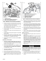
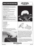
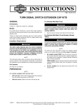
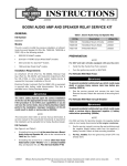
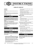
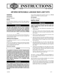
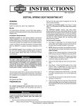
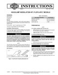
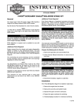
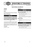
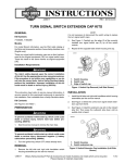
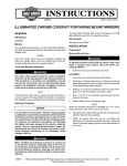
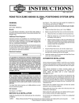
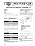
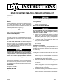
-J04531
REV. 2008-12-23
ROAD TECH ZUMO XM SATELLITE RADIO ANTENNA KIT
GENERAL
Kit Number
To prevent accidental vehicle start-up, which could cause
death or serious injury, remove main fuse before proceeding. (00251b)
92382-08A
Models
This XM Satellite Radio Antenna Kit is an optional accessory
for the Road Tech™ Zumo® GPS (Part No. 92357-08) on
specific model motorcycles. For model fitment information, see
the P&A retail catalog or the Parts and Accessories section of
www.harley-davidson.com (English only).
NOTE
1.
Refer to the service manual and follow the instructions
given to remove the main fuse.
Models with main CIRCUIT BREAKER:
XM satellite radio is available within the continental United
States. It is not available in Alaska or Hawaii.
To prevent accidental vehicle start-up, which could cause
death or serious injury, disconnect negative (-) battery
cable before proceeding. (00048a)
Additional Parts Required
1.
Refer to the service manual and follow the instructions
given to remove the seat and disconnect the negative
(black) battery cable from the negative (-) battery terminal.
Retain all seat mounting hardware.
2.
If not already in place, install the Road Tech Zumo GPS
mount per the instructions in that kit.
3.
Remove the outer fairing and windshield. Refer to the
service manual.
NOTE
Along with the Road Tech Zumo GPS and GPS mounting kit,
an XM satellite radio subscription is required, for an additional
fee.
For FLHT models without radio: See the P&A retail catalog
or the Parts and Accessories section of www.harley-davidson.com (English only) for a selection of Genuine Motor
Accessory earbuds or helmet headsets that will allow use of
the XM satellite radio and the turn-by-turn voice instruction
feature of the Road Tech Zumo.
The rider's safety depends upon the correct installation
of this kit. Use the appropriate service manual procedures.
If the procedure is not within your capabilities or you do
not have the correct tools, have a Harley-Davidson dealer
perform the installation. Improper installation of this kit
could result in death or serious injury. (00333a)
NOTE
This instruction sheet refers to service manual information. A
service manual for this year/model motorcycle is required for
this installation and is available from a Harley-Davidson dealer.
Installation, FLH models
See Figure 1. The XM antenna (1) will be positioned on top of
the AM/FM radio receiver (2), or storage box (on models without
an AM/FM radio).
Mount the antenna as far toward the front of the vehicle as
possible without extending beyond the front edge of the radio
or storage box.
1.
Obtain the XM antenna from the kit. Clean the top of the
radio or storage box, and the underside of the antenna
with a mixture of 50 to 70% isopropyl alcohol and 30 to
50% distilled water. Allow to dry thoroughly.
2.
Obtain the four Dual Lock™ reclosable fasteners (3) from
the kit. Peel the liner from the adhesive backing of two of
the fasteners.
Carefully position the fasteners to the underside of the
antenna, keeping about a 1/4-inch (6 mm) gap between
the pieces, and press firmly into place. Trim the fasteners
close to the perimeter of the antenna.
Kit Contents
See Figure 3 and Table 1.
INSTALLATION
Preparation
Assemble the remaining Dual Lock fasteners squarely to
the fasteners on the antenna.
Models with main FUSE:
Peel the liner from the adhesive backing of the fasteners.
-J04531
3.
1 of 3
is05904
3
is04940
1
2
3
4
1
1
5
2
1.
2.
3.
4.
5.
1. XM radio antenna
2. Radio receiver (shown) or storage box
3. Dual Lock reclosable fastener (4)
Figure 2. XM Radio Bracket Installation (FLT Models)
6.
Position the antenna bracket (3) to the side of the radio
carrier bracket (5) with the angled tab (4) aligned with the
front of the radio bracket.
7.
Line up the hole in the antenna bracket with the remaining
radio mounting hole. Fasten the antenna bracket through
the radio carrier bracket to the radio with one of the screws
removed earlier. Tighten to 35-45 in-lbs (4.0-5.1 Nm).
8.
Route the antenna cable down to the steering neck, and
up to the left side of the handlebar. Ensure enough slack
for steering.
Plug the antenna cable into the GPS cradle. Use cable
straps (5) from the kit to secure the cable to the handlebar.
Figure 1. XM Radio Antenna Installation (FLH Models)
4.
Position the antenna in the desired location on the top of
the radio or storage box, and press firmly into place. Hold
for about sixty seconds to set the adhesive.
After releasing pressure, allow about twenty minutes
before exerting force on the antenna.
Right-side radio mounting screws (2)
Button head cap screw from kit
Antenna mounting bracket
Angled tab on bracket
Radio carrier bracket
5.
Remove the GPS cradle mount and mounting base from
the inner fairing.
6.
Route the antenna cable up through the GPS grommet in
the fairing.
9.
7.
Install the GPS mounting base and tighten to 50-60 in-lbs
(5.65-6.78 Nm).
Return to Service
8.
Reinstall the GPS cradle to the mounting base, routing
the antenna cable in the channel between the base and
cradle. Tighten to 14-20 in-lbs (1.58-2.26 Nm).
9.
Plug the antenna cable into the cradle. Proceed to Return
to Service.
Installation, FLTR models
1.
2.
See Figure 3. Obtain the XM satellite radio antenna (1),
the antenna mounting bracket (4) and two flat head screws
(2) from the kit. Position the antenna over the mounting
bracket in the orientation shown.
Line up the mounting holes on the underside of the
antenna with the holes in the bracket. Fasten the antenna
to the bracket with the flat head screws, and tighten to
6-10 in-lbs (0.68-1.13 Nm).
3.
See Figure 2. Obtain the 1/4-20 x 5/8 inch button head
cap screw (2) from the kit.
4.
Remove the two right-side radio mounting screws (1).
5.
Insert the new button head cap screw (2) into the upper
(rearward) radio mounting hole, through the radio carrier
bracket to the radio, and tighten to 35-45 in-lbs (4.0-5.1
Nm).
-J04531
10. Verify that the Ignition/Light Key Switch is turned to the
OFF position.
Models with main FUSE: Refer to the service manual
and follow the instructions given to install the main fuse.
Models with main CIRCUIT BREAKER: Apply a light
coat of Harley-Davidson electrical contact lubricant (part
number 99861-02), petroleum jelly or corrosion retardant
material to the negative battery terminal. Refer to the service manual and follow the instructions given to attach the
negative battery cable.
Refer to the service manual, and follow instructions to
install the seat.
After installing seat, pull upward on seat to be sure it is
locked in position. While riding, a loose seat can shift
causing loss of control, which could result in death or
serious injury. (00070b)
11. Test the XM antenna by navigating to the XM functions in
the GPS unit. See the Road Tech Zumo user manual.
12. Install the outer fairing and windshield. Refer to the service
manual.
2 of 3
SERVICE PARTS
is04926a
1
3
4
A
2
6
5
2
Figure 3. Service Parts, XM Satellite Radio Antenna
Table 1. Service Parts Table
Item
Description (Quantity)
Part Number
1
Antenna, Zumo XM satellite radio
Not sold separately
2
Flat head screw, M3 x 8 mm long (2)
4496M
3
Hex socket button head screw, 1/4-20 x 5/8 inch long
924
4
Bracket, antenna mounting (for FLTR models)
Not sold separately
5
Cable strap (4)
10006
6
Fastener, reclosable, Dual Lock™ (4)
76434-06
Item mentioned in text, but not included in kit:
A
-J04531
Radio mounting screw
3 of 3