1
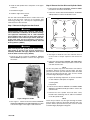
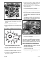
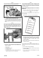
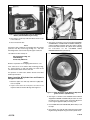
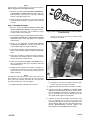
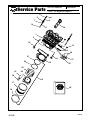
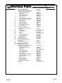
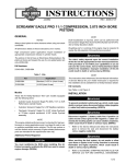
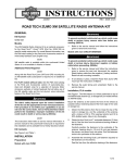
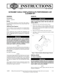
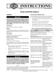
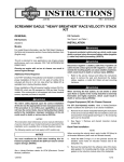
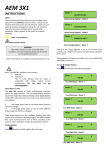
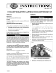
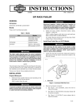
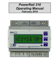
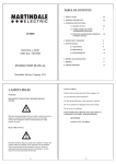
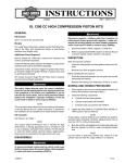
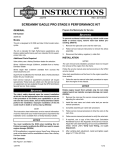
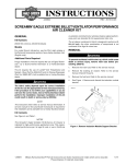
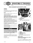
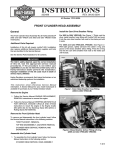
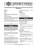
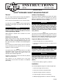
INSTRUCTIONS
®
REV. 06-23-2005
-J03796
Kit Number 29868-06
V-ROD® SCREAMIN’ EAGLE® BIG-BORE STAGE KIT
General
Additional Tools Required
The street legal V-Rod Screamin’ Eagle (SE) Big-Bore
Stage Kit fits Harley-Davidson 2006 VRSCA models.
See the Service Parts illustration for a list of the kit contents.
NOTE
A V-Rod with an installed V-Rod Screamin’ Eagle Big-Bore
Stage Kit is street legal in 50 states when used with the
stock mufflers.
CAUTION
You must recalibrate the ECM when installing this kit.
Failure to properly recalibrate the ECM can result in
severe engine damage. (00399b)
ECM calibration is required and is available for use with
stock mufflers.
Additional Parts Required
Engine removal from the chassis and engine disassembly
require a number of new replacement parts. The new
gaskets are found in the Engine Overhaul Gasket Kit (Part
No. 17011-01K), which is included in the V-Rod SE Big-Bore
Stage Kit.
The connecting rod journal bearings and the crankshaft
journal bearings must be replaced with new bearings
regardless of service wear limits.
NOTE
The Specifications and Service Wear Limits for the V-Rod
SE Big-Bore engine are the same as the those for the
VRSCSE Screamin’ Eagle 1250 engine found in the
VRSCSE Service Manual Supplement.
Inspection of other parts for service wear limits may indicate
additional part replacement.
Part numbers for any required new or worn part
replacements can be found in the VRSC or the VRSCSE
parts catalog.
Each Service Manual or Supplement procedure will require
special tools. These tools are specified in the Service
Manual or Supplement and are available through the SPX
Kent-Moore Special Service Tools catalogue.
1WARNING
The rider’s safety depends upon the correct installation
of this kit. Use the appropriate service manual procedures. If the procedure is not within your capabilities or
you do not have the correct tools, have a HarleyDavidson dealer perform the installation. Improper
installation of this kit could result in death or serious
injury. (00333a)
NOTE
This instruction sheet directs the installer to both the Service
Manual and the Service Manual Supplement. A Service
Manual and a Service Manual Supplement for the year and
model motorcycle is available at a Harley-Davidson Dealer.
Prepare the Motorcycle for Service
1. Remove the right side cover and the Maxi-Fuse.
2. Follow Service Manual instructions to remove the air
box cover.
1WARNING
To prevent accidental vehicle start-up, which could
cause death or serious injury, disconnect battery cables
(negative (-) cable first) before proceeding. (00307a)
1WARNING
Disconnect negative (-) battery cable first. If positive (+)
cable should contact ground with negative (-) cable connected, the resulting sparks can cause a battery explosion, which could result in death or serious injury.
(00049a)
3. Disconnect the battery, negative (-) cable first.
Installation
The V-Rod SE Big-Bore Stage Kit is installed in eight steps:
1. Remove the engine from the chassis.
2. Remove the cam drive and cylinder heads.
3. Separate the upper and lower crankcases.
4. Prepare the upper crankcase for machining.
5. Order/packaging procedure for crankcase machining.
1 of 10
6. Install the SE cylinder liners and pistons in the upper
crankcase.
7. Assemble the engine.
8. Install the engine in the chassis.
NOTE
The box and foam hold-down blocks found in the kit are
used to ship the upper crankcase for machining. May
Technology & Mfg., Inc., will ship the completed upper
crankcase back in the same box.
Step 2. Remove the Cam Drive and Cylinder Heads
1. Follow the Service Manual ENGINE: THROTTLE BODY
procedure to remove the throttle body.
2. Follow the Service Manual ELECTRICAL: ALTERNATOR procedure to remove the alternator cover.
i07685
10
9
11
Step 1. Remove the Engine from the Chassis
1WARNING
Coolant mixture contains toxic chemicals, which may be
fatal if swallowed. If swallowed, do not induce vomiting;
call a physician immediately. Use in a well ventilated
area. Irritation to skin or eyes can occur from vapors or
direct contact. In case of skin or eye contact, flush thoroughly with water and go to hospital, if necessary.
Dispose of used coolant according to federal, state and
local regulations. (00092a)
1WARNING
When servicing the fuel system, do not smoke or allow
open flame or sparks in the vicinity. Gasoline is
extremely flammable and highly explosive, which could
result in death or serious injury. (00330a)
1. Follow the Service Manual CHASSIS: ENGINE
REPLACEMENT procedure to remove the engine from
the chassis.
1
5
8
2
4
3
7
6
Figure 2. Cam Cover Torque Sequence
3. See Figure 2. Break the cam cover fasteners loose in
reverse order of torque sequence and remove the
cover.
4. Follow the Service Manual ENGINE: TOP END DISASSEMBLY, Cam Drive Removal procedure to remove the
cam drive and the cams.
i07684
NOTE
Set the cam journal caps, bolts and exhaust cam aside for
installation. Remove the bolts from the intake cam drive
sprockets and set the sprockets and bolts aside. The intake
cams will be replaced with new cams from the V-Rod
Screamin’ Eagle (SE) Big-Bore Stage Kit.
5. Inspect the following components for service wear limits
or wear indicators and replace as required:
a. Chain guides
b. Sprockets
6. Follow Service Manual ENGINE: CYLINDER HEAD
SERVICE, Head Disassembly procedure to remove the
cylinder heads.
7. Remove the front cylinder head cam drive cavity
breather tube and O-ring and set aside for installation
on the SE cylinder head.
Figure 1. Engine in Cradle
2. See Figure 1. Follow the Service Manual ENGINE:
STRIPPING MOTORCYCLE FOR SERVICE procedure
to mount the engine in the engine cradle and stand.
-J03796
NOTE
Follow the procedures only through removing the heads
from the upper crankcase. The heads and valve train components will be replaced with new parts from the V-Rod
Screamin’ Eagle (SE) Big-Bore Stage Kit.
2 of 10
4. Follow the Service Manual ENGINE: UPPER AND
LOWER CRANKCASE SERVICE, Disassembly procedure to separate the upper and lower crankcases.
i07686
5. Follow the procedure to break the counter balancer
drive gear fastener loose.
6. Invert the engine and follow the procedure to remove
the oil pan, the oil pickup and the gasket/baffle.
7. Follow the procedure to loosen the input bearing retainer fasteners.
8. Follow the procedure to loosen all four output shaft seal
retainer fasteners. Remove the two output shaft seal
retainer fasteners from the upper case leaving the loosened output shaft seal retainer fasteners in place in the
lower case.
Figure 3. Cylinder Head with Numbered Tappets
8. See Figure 3. Clean the oil film from the tappets.
Number each tappet with the number cast in the cylinder head.
9. Find the crankcase torque sequence figure in the
Service Manual. In reverse of the torque sequence,
break each of the 19 case fasteners loose a 1/4 turn
only. Then remove all the case fasteners.
i07688
9. Remove the tappets and the valve shims.
10. Inspect tappets and shims for wear indicators and
replace as required. Set aside for installation in same
location.
Step 3. Separate the Upper and Lower Crankcases
i07687
7
10
2
3
11
6
Figure 5. Separate the Lower from the Upper Crankcase
13
14
12
5
9
4
1
8
Figure 4. Clutch Side Crankcase Cover Torque
Sequence
10. See Figure 5. Carefully split the crankcase halves. If
necessary, use a rubber mallet.
NOTE
Follow the Service Manual procedure through splitting the
cases. Mark the Service Manual page and step number to
reference the starting point for reassembly. Unless there is
reason, do not remove the transmission gear shafts. Set
aside the lower case complete with transmission.
Step 4. Prepare Upper Crankcase for Machining
1. Follow Service Manual ENGINE: CRANKSHAFT, PISTON AND CYLINDER LINER procedure to remove the
piston rods, caps and crankshaft.
1. See Figure 4. Remove the clutch side crankcase cover
fasteners in reverse order of torque sequence and
remove the cover.
2. To separate the pistons from the rods, remove and discard the wrist pin retaining rings.
2. Follow the Service Manual ENGINE: CLUTCH procedure to remove the clutch.
3. Follow the procedure to install and torque the rod caps
for measurement of the big end and the small end.
3. Follow the Service Manual ENGINE: OIL PUMP procedure to remove the oil pump.
-J03796
3 of 10
NOTE
It is not necessary to measure the piston diameter or the
cylinder bore. These parts will be replaced with new.
i07689
1
NOTE
Case machining turnaround is 2 weeks. Carefully store the
chassis and miscellaneous chassis components for
reassembly. Sort engine components by Service Manual
procedures. Lubricate and store as required to prevent damage, corrosion or loss.
Step 5. Order/Packaging Procedure for Crankcase
Machining
1. Place an order electronically in the system for
crankcase machining under Part No. 24282-05K/MS.
NOTE
Enter the shipper tracking number in the “Comment” line of
the system order.
2. Print and save a copy of the order acknowledgment.
1. Cylinder liner
i07691
Figure 6. Remove the OE Cylinder Liner
4. See Figure 6. Select remover insert for the 1130 cc engine
from the CYLINDER LINER REMOVER/INSTALLER (HD45313) and follow the instruction sheet to remove cylinder
liners.
Deale
r Nu
Deale
r:
r Na
NOTE
Follow the Service Manual procedure through removing the
liners. Mark the Service Manual page and step number to
reference the starting point for reassembly. Inspect the
upper crankcase for wear or damage and clean the case for
shipping. Refer to Step 5. Order/Packaging Procedure for
Crankcase Machining.
me:
Deale
r Co
ntac
t Nam
e:
COP
S Or
der N
umb
Pick
list N
i07690
1000
mbe
Case
er:
umb
er:
Num
ber:
Figure 8. Tag
3. See Figure 8. Fill out all information on the tag supplied
in kit (dealer number and name, a dealer contact name,
the COPS order number, the Picklist number, and the
crankcase number).
4. Wipe off upper crankcase and attach the original tag to
the upper crankcase.
Figure 7. Measure for Service Wear Limit
5. See Figure 7. Measure or inspect the following components for service wear limits or wear indicators and
replace as required:
a. Primary gear
b. Rod big and small end
c. Crankshaft journal
d. Crankshaft journal bearings (These bearings are
replaced anytime the cases are separated.)
-J03796
NOTE
If the crankcase arrives at May Technology & Mfg., Inc.,
without the tag attached, the crankcase will not be
machined.
5. Place crankcase in the provided bag.
6. Place bag and crankcase in the box from the kit for
crankcase shipping.
7. Place a copy of the order acknowledgment in the shipping box from the kit.
4 of 10
i07692
i07693
Figure 9. Case in Shipping Box with Top Hold-Down
Blocks (shown without bag for clarity)
8. See Figure 9. Fit the top hold-down blocks down on top
of the crankcase.
9. Close and seal the box.
NOTE
Seal the box with a minimum of packaging tape. Box will be
opened at the May Technology & Mfg., Inc., and after
machining will be used to return ship the upper crankcase.
10. Address the box and ship to:
Figure 10. Install the SE Cylinder Liner
3. See Figure 10. Return to the Service Manual ENGINE:
CRANKSHAFT, PISTON AND CYLINDER LINER procedure and begin assembly. Select the 1250 cc cylinder
liner installer and install the SE cylinder liners following
the instructions for the CYLINDER LINER
REMOVER/INSTALLER (HD- 45313).
i07694
May Technology & Mfg., Inc.
2922 Wheeling
Kansas City, MO 64129
NOTES
Dealer is responsible for all shipping and insurance costs.
If the crankcase is not received at May Technology & Mfg.,
Inc., within 30 days of order placement, the order will be
cancelled and the dealer will be contacted.
For questions on order status, dealers should contact their
SPOC representative.
Step 6. Install the SE Cylinder Liner and Pistons in
the Upper Crankcase
1. Wash the upper case with soap and water. Lightly lubricate as required.
2. Inspect and clean the new parts from the kit as
required. Lubricate the liner O-rings with engine oil.
Figure 11. Orient SE Pistons to the Exhaust (EX) Valve
(piston shown in cylinder liner)
4. See Figure 11. Switch to the VRSCSE Service Manual
Supplement ENGINE: PISTON PIN procedure to orient
the pistons to the exhaust valves and fit the SE pistons
to the original equipment (OE) connecting rods.
5. Use PISTON PIN CLIP INSTALLER (HD-47189) to seat
the clips.
6. Check piston ring end gap with V-Rod Screamin’ Eagle
Big Bore Stage Kit piston rings located in cylinder liner.
-J03796
5 of 10
NOTE
Specifications for ring end gap are found in the Service
Manual Supplement for the VRSCSE model.
i07695
7. Return to the Service Manual ENGINE: CRANKSHAFT,
PISTON AND CYLINDER LINER procedure and complete installation of the pistons, rods and rod bearing
journals in the upper engine case.
8. Continue with the procedures to select and install rod
journal bearings; install the crankshaft and connecting
rod caps.
Step 7. Assemble the Engine
1. Return to the Service Manual ENGINE: UPPER AND
LOWER CRANKCASE SERVICE and page forward to
the Assembly procedure and assemble the upper
crankcase to the lower crankcase.
Figure 12. Drive Sprocket Orientation to Front Cylinder
Intake Camshaft
a. See Figure 12. For the front cylinder, orient the spacer boss of the drive sprocket to the SE intake
camshaft to the outside.
2. From the Main Bearing Journal Diameter table found in
the ENGINE: CRANKSHAFT, PISTON AND CYLINDER
LINER procedure, select and replace the crankshaft
main bearings.
3. Return to the ENGINE: UPPER AND LOWER
CRANKCASE SERVICE, Assembly procedure and
mate the upper and lower engine crankcases.
i07696
1
4. Follow the procedure to install and tighten the case fasteners in the specified sequence to the specified torque
value.
5. Follow the procedure to tighten the upper and lower
transmission shaft bearing retainers, the drive sprocket
flange seal retainers, and the oil pan.
6. Follow Service Manual ENGINE: CAM DRIVE procedure to assemble the triple gear, the primary chain and
the fixed tensioners.
7. Holding the drive sprocket of the intake camshafts in a
soft-jawed vise, break loose the two bolts holding the
intake camshafts to the sprockets and remove the
intake camshafts.
NOTE
The drive sprockets will only fit the intake cams in one orientation. Match the cam and drive sprocket with the double
dots to the front cylinder, and match the cam and drive
sprocket with three dots to the rear cylinder
8. Install the SE intake camshafts to the sprocket.
1.
Spacer boss
Figure 13. Spacer Boss on Inside of Rear Cylinder Cam
b. See Figure 13. For the rear cylinder, orient the spacer boss of the drive sprocket to the inside.
9. Tighten the drive sprocket fasteners to 23 Nm (17 ft-lbs).
10. Follow Service Manual ENGINE: CYLINDER HEAD
SERVICE, Head Assembly procedures. Search procedure for installing the valve shims and tappets, and continue to install the cams and cam journal caps on the
SE cylinder heads. Tighten to specification.
11. Continue to follow the procedure and measure valve
lash. If required, use a copy of the Valve Lash
Calculation Worksheet found in the Appendix of the
Service Manual. Adjust the valve lash following Service
Manual MAINTENANCE: VALVE LASH, Lash
Measurement and Lash Adjustment procedures.
-J03796
6 of 10
12. Follow Service Manual ENGINE: CYLINDER HEADS,
Installation procedure to install the SE cylinder heads.
13. Follow Service Manual ENGINE: INSTALLING AND
TIMING THE CAMS procedure to time the cams to the
cam drive.
14. Follow Service Manual MAINTENANCE: VALVE LASH,
Lash Measurement procedure to verify the valve lash.
15. If required, use a copy of the Valve Lash Calculation
Worksheet found in the Appendix of the Service
Manual. Adjust the valve lash following Service Manual
MAINTENANCE: VALVE LASH, Verify Cam Timing,
and Lash Adjustment procedures.
16. After verifying lash adjustment, install and tighten spark
plugs to 23 Nm (17 ft-lbs).
17. Apply a thin coat of grease, to the rubber O-ring and
groove of the brass cam cavity breather tube and press
into the cam drive breather hole in the front cylinder.
18. Continue the Service Manual ENGINE: INSTALLING
AND TIMING THE CAMS procedure to install the gaskets and cam covers.
19. Follow the procedure to install the ball gear, needle
roller bearing, thrust washer, and starter limiter gear.
20. Follow the procedure to install the rotor shell with the
integral ball clutch.
21. Follow the ELECTRICAL: ALTERNATOR procedure to
install the alternator cover.
22. Follow the Service Manual ENGINE: OIL PUMP,
Replacement procedure to install the oil pump.
23. Follow the Service Manual ENGINE: CLUTCH,
Installation procedure to install the clutch and the clutch
side crankcase cover.
24. Follow the Service Manual ENGINE: THROTTLE
BODY, Installation procedure to install the throttle body.
25. Install the engine label bracket and the Screamin’ Eagle
engine label insert.
Step 8. Install the Engine in the Chassis
1WARNING
Coolant mixture contains toxic chemicals, which may be
fatal if swallowed. If swallowed, do not induce vomiting;
call a physician immediately. Use in a well ventilated
area. Irritation to skin or eyes can occur from vapors or
direct contact. In case of skin or eye contact, flush thoroughly with water and go to hospital, if necessary.
Dispose of used coolant according to federal, state and
local regulations. (00092a)
1WARNING
When servicing the fuel system, do not smoke or allow
open flame or sparks in the vicinity. Gasoline is
extremely flammable and highly explosive, which could
result in death or serious injury. (00330a)
1. Follow Service Manual CHASSIS: ENGINE REPLACEMENT, Installation procedure to install the engine in the
chassis.
CAUTION
You must recalibrate the ECM when installing this kit.
Failure to properly recalibrate the ECM can result in
severe engine damage. (00399b)
NOTE
The remapping will be supplied through any authorized
Harley-Davidson Dealer.
2. Before starting the engine, recalibrate the ECM.
NOTE
The product information label contained in this kit is required
in the state of California only. This Executive Order label is
required to aid in passing the California Smog Check
Program. Place the information label on the right side of the
frame directly beneath the VIN sticker. Do not place the
label on motorcycles other than those specified in the
Instruction Sheet.
3. Install the Executive Order (EO) label on your motorcycle.
Return the Motorcycle to Service
1WARNING
Connect positive (+) battery cable first. If positive (+)
cable should contact ground with negative (-) cable connected, the resulting sparks can cause a battery explosion, which could result in death or serious injury.
(00068a)
1. Install the Maxi-Fuse and the right side cover.
2. Reconnect the battery, positive (+) cable first.
-J03796
7 of 10
1WARNING
1WARNING
When closing the seat, make sure the ignition switch is
in the fuel position. If the ignition switch is in any other
position when the seat is closed, the seat latch mechanism could be damaged. (00196a)
Travel at speeds appropriate for road and conditions
and never travel faster than posted speed limit.
Excessive speed can cause loss of vehicle control,
which could result in death or serious injury. (00008a)
3. Close the seat.
Test Run Motorcycle
1WARNING
Be sure that all lights and switches operate properly
before operating motorcycle. Low visibility of rider can
result in death or serious injury. (00316a)
-J03796
1. Test start engine. If the oil pressure indicator lamp illuminates, follow the Service Manual ENGINE: OIL
PRESSURE, Checking Oil Pressure procedure to troubleshoot the problem.
2. If there is a rattle heard during engine start-up, follow
Service Manual MAINTENANCE: SECONDARY CAM
CHAIN procedure to adjust the secondary cam chain.
3. Test ride motorcycle and adjust controls, belt tension,
wheel alignment, headlamp alignment, etc., as required.
8 of 10
®
Service Parts
i07646
Part No. 29868-06
Date 06/05
V-Rod® SE Big-Bore Stage Kit
8
5
6
4
7
14
24
11
1
2
10
12
3
26
21
9
22
13
27
25
23
19
20
18
15
17
16
-J03796
28
9 of 10
®
Service Parts
Item
1
Description (Quantity)
Front cylinder head assembly silver
Includes the following items 2-14
2
Screw, SHCS, M5-.8 x 10
3
Stud bolt (2)
4
Valve spring, inner (4)
5
Valve spring, outer (4)
6
Valve collar (8)
7
Valve spring retainer, lower (4)
8
Valve spring retainer, upper (4)
9
Exhaust valve (2)
10
Intake valve (2)
11
Valve stem seal (4)
12
Expansion plug (2)
13
Front cylinder head gasket
14
Guide, valve (4)
15
Piston liner assembly (2)
Includes the following items 16-23
16
O-ring (2)
17
Cylinder liner
18
Retaining ring (2)
19
Piston pin
20
Piston
21
Ring, top compression
22
Ring, 2nd compression
23
Ring, oil control
24
Intake camshaft (2)
25
SE engine label insert (2)
26
Screw, countersunk hex socket,
M3-0.5 x 8 (4)
27
Engine label bracket (2)
28
Engine overhaul gasket kit
The following items are not shown.
Rear cylinder head assembly silver
Includes the following items
Screw, SHCS, M5-0.8 x 10
Stud bolt (2)
Cam chain jet
Valve spring, inner (4)
Valve spring, outer (4)
Valve collar (8)
Valve spring retainer, lower (4)
Valve spring retainer, upper (4)
Exhaust valve (2)
Intake valve (2)
Valve stem seal (4)
Expansion plug (2)
Rear cylinder head gasket
EO label
-J03796
Part No. 29868-06
Date 06/05
V-Rod® SE Big-Bore Stage Kit
Part No.
17212-06K
1043MA
16448-01KA
18052-01K
18055-01K
18057-01K
18661-01K
18662-01K
18663-01K
18664-01K
18687-01K
769M
17691-05K
18665-01K
22928-05K
11314K
Not sold separately
22121-01K
22126-05K
Not sold separately
22930-05K
22931-05K
22932-05K
17431-05K
29530-05K
4496M
69280-05K
17011-1K
17213-06K
1043MA
16448-01KA
Not sold separately
18052-01K
18055-01K
18057-01K
18661-01K
18662-01K
18663-01K
18664-01K
18687-01K
769M
17692-05K
Not sold separately
10 of 10