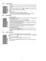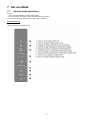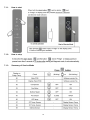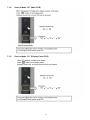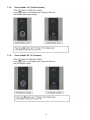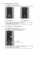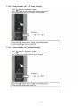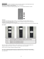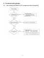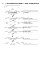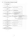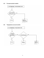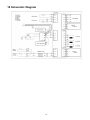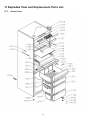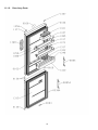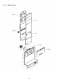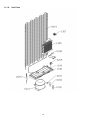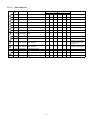
1
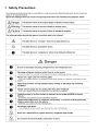
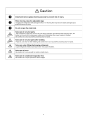
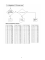
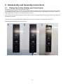
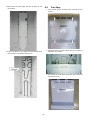
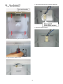
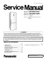
Order Number GORR1309001CE
REFRIGERATOR-FREEZER
Model No. NR-BN31AS1
Model No. NR-BN31AW1
Product-Color
S:Inox-look
W:White
Destination E(Europe Continental) except France
F(France)
B(U.K.)
TABLE OF CONTENTS
1
2
3
4
5
6
7
8
9
10
PAGE
Safety Precautions----------------------------------------------- 2
Specifications ----------------------------------------------------- 5
Technical Descriptions ----------------------------------------- 6
Location of Controls and Components ------------------- 8
Installation Instructions ---------------------------------------10
Operating Instructions-----------------------------------------12
Service Mode -----------------------------------------------------15
Troubleshooting Guide ----------------------------------------25
Disassembly and Assembly Instructions ---------------31
Schematic Diagram ---------------------------------------------43
PAGE
11 Exploded View and Replacement Parts List ----------- 44
© Panasonic Corporation 2013 Unauthorized copying
and distribution is a violation of law.
1 Safety Precautions
2
3
4
2 Specifications
Model
Volume capacity
External dimensions
NR-BN31AS1
NR-BN31AW1
Total effective volume capacity
307 L
Fridge compartment (PC)
222 L
Freezer compartment (FC)
85 L
Width/ Depth/ Height (mm)
600 mm x 637 mm x 1,850 mm
side : 20 mm or more
Installation size
Back : 50 mm or more
Top : 150 mm or more
Power supply plug
Rating
250V/10A
Power supply code
Length
2050 mm
Interior lamp (LED)
Rating
230V/2W
IEC protection against electric shock classes
Class I
Climate Class
SN-T
Fridge compartment sensor
PCC
ESCOP B57020-M2502
Freezer compartment sensor
FCC
ESCOP B57020-M2502
Ambient temperature sensor
ATC
Not used
Defrost temperature sensor
DFC
ESCOP B57020-M2502
Model
Compressor
NLU8.0KK.1
Rotation speed
3000 rpm
Curled resistance cord (at 25°C)
Model
In side the compressor
Operating temperature without power
Overlord relay
Main wiring : 26 Ohm
Aux wiring : 23 Ohm
110 °C ~ 130 °C
Return temperature
65 °C ~ 90 °C
Operating current (A)
Make = 7.5A
Break = 4.5A
Fan motor
Model/Rating
Dumper
Rating / Voltage
Defrost heater
Rating
Thermal fuse
Class / Fill
BG1512,220/240V,50/60Hz,2W
12VDC.60mA
190 W
Class II.72 ℃
Oil charge
270ml
Freezing ability
12 kg /24 H
Values of the energy consumption
234.7kwh/year
Energy efficiency grade
A++
Refrigerant charge
R600a / 58g
Measurement of exterior noise emitted
42 dB
Form polyurethane
Net weight (kg)
Cyclo - pentane
Without packaged
75kg
Name Plate
5
3 Technical Descriptions
Single-compressor cooling system
On the basis of temperature checking with sensor in fridge compartment and temperature in freezer
compartment, the request for switch-on/off of compressor and Fan Motor is set /deleted
Compressor operation
In normal mode of operation the compressor functions with the frequency which is prescribed with regard to the
actual conditions of regulations.
The condition for compressor switch-on is not considered if the compressor is locked due to min switch-off time
which is 5 minutes
The same is valid for compressor switch-off, when the compressor does not switch off until the min switch-on
time is reached which is 5 minutes.
PC Damper operation
The PC Damper can be opened only to the extreme position, or completely closed.
At switching-on it is necessary to set the PC Damper, so that it can be opened and closed. It is reset when the
parameter “max time of PC Damper position” which is 6 hours, expires. This time is considered when the PC Damper is in one
position, open or closed.
It is not possible to set the PC Damper during defrosting.
Whenever the PC Damper opens, the Fan Motor starts to function.
When the PC Damper is closed, the Fan Motor operates according to its regulation.
Opening or closing any door does not affect the PC Damper operation.
Fan Motor operation
The Fan Motor switches on when the request is made for cooling of fridge or freezer compartment. When a request
is made for cooling of fridge compartment, first the PC Damper opens and after 30 seconds, the Fan Motor switches on.
Fan Motor switches on with time delay after the compressor start-up - depending on the last
cycle.
If the last cycle was a normal cycle, the Fan Motor switches on immediately.
After defrosting of the evaporator, the Fan Motor starts to function after 4 minutes.
Fan Motor operation is suspended if the freezer or refrigerator door is opened.
When the door is closed, the Fan Motor switches-on after 5 seconds.
If the door is open for 20 minutes, normal operation of Fan Motor continues as prescribed by regulation of cooling.
LED Lamp
Fridge compartment LED Lamp switches on when the door opens.
Fridge compartment LED Lamp switches off when the door closes.
In case of open door, the incorporated time limitation becomes active which switches off the LED Lamp after
10 minutes
Condition for cooling of fridge compartment (PC)
The temperature in fridge compartment can be set from +1 to +9 °C.
Based on the verification of the temperature in fridge compartment, the request for cooling of fridge
compartment is set or deleted.
When the temperature in fridge compartment is equal to or rises above +1 °C, the PC Damper opens and after 30
seconds (Fan Motor switch-on delay time due to PC Damper switch-on) the Fan Motor in freezer compartment switches on, too.
When the temperature in fridge compartment is lower than +1 °C, the PC Damper closes, and in case the request for
cooling of freezer compartment is not set, the Fan Motor in freezer compartment switches off.
On the basis of request for cooling of fridge compartment, the PC Damper and Fan Motor in the freezer compartment switch on.
6
Condition for fridge of freezer compartment (FC)
Standard compressor
The temperature in freezer compartment can be set from -16°C to -24°C.
It operates according to the principle of setting/deleting the request for cooling of freezer compartment.
When the temperature in the freezer compartment is equal to or rises above +1 ° C, the compressor and Fan Motor
(in normal operation) switch on or, after the expiry of Fan Motor switch-on delay time after defrosting, the Fan Motor of
freezer compartment switches on, too.
When the temperature in freezer compartment is lower than 0 ° C, the request for cooling of freezer
compartment is deleted; the compressor and Fan Motor of freezer compartment switch off.
Based on request for cooling of freezer compartment the compressor and Fan Motor of freezer compartment are
controlled.
Defrosting
Unconditional start of defrosting is installed in the following cases:
1.
2.
3.
4.
At switch-on of "Fast Freeze" function if the compressor of freezer compartment does not function.
At switch-on of "Super Cool" function if the compressor of freezer compartment does not function.
At switch-on of "Extreme Freeze" function if the compressor of freezer compartment does not function
If, at switch on of "Fast Freeze" or "Super Cool" function the compressor functions without interruption for 1
hour i.e. immediately after the first interruption of operation of compressor.
5. Always after the terminated "Super Cool", "Extreme Freeze" and "Fast Freeze" function.
6. In case when the user interrupts the "Fast Freeze" function later than in 8 h after switching-on this function.
7
4 Location of Controls and Components
4.1.
Display and Control Panel
8
4.2.
Components
9
5 Installation Instructions
10
11
6 Operating Instructions
6.1.
Setting the temperature
6.1.1.
Fridge compartment (PC)
6.1.2.
Freezer compartment (FC)
6.1.3.
Fresh Zone Crisper
6.2.
6.2.1.
Functions
Super Cool Mode
12
6.2.2.
Super Freeze Mode
6.2.3.
Jet Freeze Mode
6.2.4.
ECO Mode
13
6.2.5.
Holiday Mode
6.2.6.
Alarm Mode
6.2.7.
Child safety lock
14
7 Service Mode
7.1.
Service mode operations
General
• Service mode is intended for service interventions
• In service mode it is possible to select optionally among the outputs
• From service mode we always enter normal mode of operation
Display Panel A’ssy
Display Panel A’ssy on appliance door
15
7.1.1.
How to start
7.1.2.
How to stop
7.1.3.
Summary of Service Mode
16
7.1.4.
Service Mode “00” (Main PCB)
7.1.5.
Service Mode “01” (Display Panel PCB)
17
7.1.6.
Service Mode “02” (Compressor)
7.1.7.
Service Mode “03” (Fan Motor)
18
7.1.8.
Service Mode “04” (Defrost Heater)
7.1.9.
Service Mode”05” (PC Damper)
19
7.1.10. Service Mode “06” (LED Lamp)
7.1.11.
Service Mode “07” (PC Temp. Sensor)
20
7.1.12. Service Mode “08” (FC Temp. Sensor)
7.1.13. Service Mode “09” (Defrost Sensor)
21
7.2.
Measuring Points on Main PCB Box
Note: For more detail, refer to the Schematic Diagram on page 44.
7.3.
Value of Temperature sensors
22
7.4.
Operation in case of failure
Failure of magnetic switch (LED Lamp)
In case of failure of magnetic door switch, the LED Lamp stays switched on for 10 minutes, even when door is
closed. During this time the appliance is operating normally and in accordance with the settings.
Failure of Temperature Sensors
Fridge compartment (PC)
Failure of PC sensor in fridge compartment: time algorithm is installed which sets and deletes the request for
cooling of fridge compartment i.e. opening of the PC Damper:
• for 15 minutes the PC Damper is open
• for 30 minutes the PC Damper is closed
When the PC Damper opens, the Fan Motor switches on and when the PC Damper closes, the Fan Motor switches off. Display for
Fridge
temperature displays ''E1''.
Freezer compartment (FC)
Failure of FC sensor in freezer compartment: display shows ''E3''. The request for cooling of freezer
compartment i.e. switch on/off of compressor and Fan Motor is activated in cycles:
• 15 minutes ON.
• 40 minutes OFF.
If the request for Fan Motor operation in one compartment is interrupted and other compartment requires Fan Motor
operation, the Fan Motor functions.
Freezer compartment evaporator
Failure of Defrost sensor on freezer compartment evaporator: start of defrosting according to the prescribed total
time of compressor operation. Defrosting is carried out normally, but the temperature at which the Defrost
heater switches off, is +8°C.
Failure of fridge and freezer compartment Temperature sensor at the same time
In this case the display of temperature in fridge compartment shows "E1" and the display of temperature in
freezer compartment shows "E3".
On models with one-digit temperature display in fridge compartment, "E" and "1" are shown alternately,
with 1-second interval while the regulations function each one in accordance with their time regime.
Alarms
Alarms of too high temperature in fridge/freezer compartment
In case the temperature in fridge compartment exceeds +13 ° C and in freezer compartment -9 ° C, the high
temperature alarm will be activated:
• sound alarm is heard, the key for cancellation of alarm is flashing with frequency 1 Hz (0.5 seconds ON and 5
seconds OFF), and on the display, depending on the compartment in which the temperature has raised above
the alarm temperature, the set temperature is flashing.
• Sound alarm is the interrupted buzzer sound: 15 seconds ON and 15 seconds OFF in the first 5 minutes every hour.
• Sound alarm is cancelled by pressing the key for cancellation of the alarm.
• Flashing of key and set temperature remains active until the appliance has cooled down and the temperature
drops below the alarm value.
• If within 24 hours after the cancellation of the sound alarm the appliance does not cool down below the alarm
temperature, the sound alarm is activated again.
Alarm due to power supply failure (blackout) during appliance operation
In case that during a power failure the appliance has heated up to the alarm temperature (+13°C in fridge or 9°C in freezer compartment), after the restoration of power supply, the alarm of too high temperature is activated.
In case the alarm of too high temperature is activated due to power supply failure, unlike in case of too high
temperature alarm, the number -16 on freezer or +9 on refrigeration display start flashing. In this case the
alarm is active until user’s cancellation.
23
Open door alarm
If the door of fridge or freezer compartment is open for more than 2 minutes, the uninterrupted buzzer sound
will be heard and the key "1" for cancellation of the alarm will be flashing.
When the door is closed, the alarm is canceled.
The sound alarm can also be cancelled by pressing the key "1"; the key flashes until the door is closed.
Child lock
The function is activated by long press on the key "1" for cancellation of the alarm, the display shows "LL".
By pressing any key, the display will show "LL"; when the key is released, the display shows set temperature.
"Child lock" is cancelled by long press on the key "1".
In case the alarm is activated, it can be cancelled with alarm cancellation key without having to leave the "Child lock" mode.
Error display
Error "E1" is shown on temperature display in fridge compartment. For models with single-digit display, the
display alternately shows the errors: 1 second "E", 1 second "number" and 1 second zero.
Error E3 is shown on freezer compartment temperature display.
Error "E0": on models with two displays it is shown on fridge and freezer compartment temperature display.
For models with single-digit display, the display alternately shows the errors: 1 second "E", 1 second "number"
and 1 second zero.
24
8 Troubleshooting Guide
8.1.
Not cooling at all [ Both PC & FC (compressor does not operate)]
25
8.2.
PC is not cooling or poor cooling. [ FC cooling condition is normal]
26
8.3.
FC is not cooling. [ Compressor operate]
27
8.4.
Cooling system trouble.
28
8.5.
Communication trouble.
8.6.
Temperature sensor trouble.
29
30
9 Disassembly and Assembly Instructions
9.1.
Display Panel A’ssy (Display and Control Panel)
Before taking any action, please unplug the power supply.
To separate Display Panel A’ssy from the door, insert flat screw driver (picture B) into the small opening on the down side in the middle of Display Panel A’ssy. Before you do that please protect the door with scotch tape. Carefully lift the screw driver to detach the
Display Panel A’ssy. Be careful not to damage cable with connector.
On the control unit there are two terminal connectors. Right one is for connecting Display Panel A’ssy with power board. Left is for
uploading SW (optional).
There are also two connectors with cable inside the opening. One for each side of door opening option (picture C).
NB! Please wear electrostatic discharge wrist band
31
9.2.
LED Lamp PC
9.3.
1. LED Lamp is installed at the ceiling of PC
Main PCB
1. Main PCB is installed at the upper side of refrigerator.
2. Unhook the hook and push the LED cover to the
left.
2. Slide both the Head Panel Cover R and the Head Panel
Cover L to remove.
3. Remove LED Lamp Assy and disconnect the connector.
3. Unscrew the two screws fixing the Head Panel Cover
Center and remove it.
4. Disconnect the connector.
32
9.4.
5. While unhooking the rib at the upper center of PCB box
by inserting the screwdriver, draw out the PCB box
toward you.
Air Flow Ins. PC
1. First, remove the Glass Shelves, Bottle Support and
Drawers, then unscrew the two screws.
6. Unhook the connector’s hook, then disconnect the connectors.
2. Remove the PC Air Duct Lower.
7. Main PCB Assy (Main PCB with PCB box)
33
9.5.
3. Remove the PC Duct Upper, then the Air Flow Ins. PC
can be seen.
Fan Assy
1. First, remove the FC Drawers, then unscrew the four
screws.
2. Pull the FC Air Duct Cover toward, then the connector of
Fan Motor can be seen.
4. Pull the Air Flow Ins. PC slightly from the left side, then
the connector of Air damper can be seen.
3. Unhook the six hooks at the back side, then remove the
FC Air Duct Cover.
34
9.6.
Door Switch FC
4. Unhook the hook, then remove the Door Switch FC.
1. First, remove the FC Drawers,
5. Disconnect the connector.
2. Unscrew the screw fixing the Door Switch Cover.
3. Open the Door Switch Cover.
35
9.7.
Replacement of PC temperature sensor
4. First crimp the enclosed end splices on conductor of the
new sensor.
Place the enclosed thermo-shrinkable bushing.
Crimp end splices on conductors of cut cable.
1. Release the latches by screwdriver and remove the cover
by hand.
Note: The sensor cover is hooked at two position as
shown in the photo.
2. Cut off the damages sensor at the base of sensor head.
5. Use hair dryer and heat the bushings so that they tightly
wrap the conductors and prevent moisture from breaking
through the joint.
3. Strip off approx. 25mm of additional cable insulation and
5mm of basic insulation of the conductor.
6. Place the sensor into its seat and replace the sensor
cover.
36
9.8.
Positions of Temperature Sensors, Thermal Fuse,
Defrost Heater and PC Door Switch
9.9.
Changing The doorway Direction
Warning: Make sure the unit is unplugged
37
1. Remove the Hinge Cover Upper.
5. Remove the PC Door.
2. Remove the PC Door Edge Cover Left.
6. Remove the PC Hinge Cover VC.
3. Disconnect the Display Connector.
7. Slide the Head Panel Cover Right and Head Panel
Cover Left then remove its.
4. Unscrew the screws fixing the Upper Hinge.
8. Unscrew the screws fixing the Head Panel Cover
Center and remove it.
38
9. While unhooking the rib at the center of PCB box by using
the screwdriver.
13. Unscrew the Middle Hinge fixing screw and remove it.
14. Remove the FC Door.
10. Draw out the PCB box toward you and change the electric wire direction.
15. Remove the Middle Hinge Plugs and the Screw cap
then unscrew the screw.
11. Screw the screws fixing the Head Panel Cover
Center.
16. Screw the screw.
Install the Middle Hinge Plugs and the Screw cap.
12. Slide the Head Panel Cover Left and Head Panel
Cover Right then fix it.
39
17. Lie down the appliance to the back. (min 600mm)
21. Replace the Door Bushing and the FC Door Plug.
CAUTION: Do not damage the outer condenser.
22. Remove the PC Door Limiter Right, then install PC
Door Limiter Left. (You can find the PC Door Limiter
Left in the user manual bag)
18. Replace the Levelling Leg Right with the Lower
Hinge and the Levelling Leg Left. Then raise the
appliance.
23. Turn the Middle Hinge upside down and screw it.
The thick washer on the downside.
19. Remove the FC Door Limiter Right, then install FC
Door Limiter Left. (You can find the FC Door Limiter
Left in the user manual bag)
24. Install the PC Door.
20. Assemble the FC Door.
40
25. Remove the PC Door Edge Cover Left.
29. Install the Hinge Cover.
26. Install the upper Hinge.
30. Fix the Hinge Cover VC and the PC Door Edge
Cover Right.
27. Connect the Display Connector.
31. Remove the display panel by using a small
flat-blade screwdriver.
(Refer to the Replacement of Display)
28. Screw the Upper Hinge fixing screws.
32. Replace the connector right and the connector left.
(Refer to the Replacement of Display)
41
33. Remove the Filling Plugs.
34. Unscrew the Handles fixing Torx screws using the
Torx screwdriver.
35. Screw the Handles to the right side.
36. Install the Filling Plugs to the left side.
42
10 Schematic Diagram
43
11 Exploded View and Replacement Parts List
11.1. Interior Parts
44
11.1.1.
Safety
Interior Parts List
Ref.
No.
Parts No.
NR-BN31AS1
Parts Name & Description
NR-BN31AW1
E
2
1
1
3
1
F
2
1
1
3
1
B
2
1
1
3
1
E
2
1
1
3
1
F
2
1
1
3
1
B
2
1
1
3
1
3
3
3
3
3
3
1
1
1
1
1
1
3
1
1
1
2
2
1
1
1
1
1
1
1
3
1
1
1
2
2
1
1
1
1
1
1
1
3
1
1
1
2
2
1
1
1
1
1
1
1
3
1
1
1
2
2
1
1
1
1
1
1
1
3
1
1
1
2
2
1
1
1
1
1
1
1
3
1
1
1
2
2
1
1330 CNR-435969 DRAWER LOWER FLAP ASSY PC
1
1
1
1
1
1
1331 CNR-435902 DRAWER COVER MIDDLE FC
1332 CNR-435904 DRAWER COVER UPPER FC
1333 CNR-422798 DRAWER COVER LOWER FC
1
1
1
1
1
1
1
1
1
1
1
1
1
1
1
1
1
1
1334 CNR-408609 MIDDLE HINGE
1
1
1
1
1
1
1
41
41A
69
69
100
CNR-420268
CNR-526273
CNR-697782
CNR-421098
CNR-377549
CNR-662161
MIDDLE HINGE PLUG
LEVELLING LEG M8X25
LEVELLING LEG M8X40
SCREW CAP
SCREW CAP
SENSOR COVER PC
101 CNR-108164 SENSOR
109
109
195
195
318
318
741
741
1125
1126
1318
1319
1323
1324
1325
1326
1327
CNR-409504
CNR-378242
CNR-449224
CNR-381593
CNR-421087
CNR-407929
CNR-449282
CNR-449375
CNR-449323
CNR-449324
CNR-433234
CNR-413276
CNR-410606
CNR-435886
CNR-433265
CNR-408228
CNR-413279
WASHER
WASHER
WASHER
WASHER
HINGE COVER UPPER
HINGE COVER UPPER
HINGE COVER VC
HINGE COVER VC
DRAWER SUPPORT RIGHT PC
DRAWER SUPPORT LEFT PC
GLASS SHELF UPPER ASSY PC
GLASS SHELF UPPER FC
BOTTLE SUPPORT
DRAWER COVER LOWER PC
WEEL WITH HOLDER ASSY
CONTROL BOARD PLUG
GLASS SHELF LOWER FC
1335 CNR-462227 LOWER HINGE
1
1
1
1
1
1
1336
1336
1337
1337
1338
1344
1345
1346
1352
1353
1355
2
1
2
1
3
3
1
1
1
2
1
2
1
3
3
1
1
1
2
1
2
1
3
3
1
1
1
2
1
2
1
3
3
1
1
1
2
1
2
1
3
3
1
1
1
2
1
2
1
3
3
1
1
1
1369 CNR-436703 MAIN PCB ASSY
1
1
1
1
1
1
1370 CNR-416814 DOOR SENSOR FC
1
1
1
1
1
1
1376 CNR-423339 UPPER HINGE WITH CABLE SET
1
1
1
-
-
-
1376 CNR-413689 UPPER HINGE WITH CABLE SET
-
-
-
1
1
1
1381 CNR-441983 LIGHTING LED STRIP ASSY
1
1
1
1
1
1
1394
1395
1396
1397
1
1
1
1
1
1
1
1
1
1
1
1
1
1
1
1
1
1
1
1
1
1
1
1
CNR-421088
CNR-407852
CNR-421456
CNR-408214
CNR-410410
CNR-409793
CNR-409817
CNR-409841
CNR-422799
CNR-410813
CNR-410814
CNR-407979
CNR-407982
CNR-407981
CNR-407983
HEAD PANEL COVER SIDE
HEAD PANEL COVER SIDE
HEAD PANEL COVER CENTER
HEAD PANEL COVER CENTER
SPACER
GLASS SHELF LOWER PC
GLASS SHELF PROFILE BACK PC
GLASS SHELF PROFILE FRONT FC
DRAWER UPPER PC
DRAWER UPPER PROFILE PC
GLASS SHELF PROFILE
DRAWER LOWER PC
DRAWER MIDDLE FC
DRAWER UPPER FC
DRAWER LOWER FC
45
Remarks
common sensor
PCC,FCC,DFC
with PCB box
with LED cover
11.1.2.
Door Assy Parts
46
11.1.3.
Safety
Door Assy Parts List
Ref.
No.
Parts No
Parts Name & Description
NR-BN31AS1
F
B
1
1
26 CNR-435905 NAME PLATE
29 CNR-449209 DOOR PLUG FC
1
1
1
1
1
1
29 CNR-449363 DOOR PLUG FC
1
1
1
1
1
1
83 CNR-442916 DOOR LIMITER
2
2
2
2
2
2
102 CNR-449210 FILLING PLUG
4
4
4
-
-
-
102 CNR-420247 FILLING PLUG
-
-
-
4
4
4
136 CNR-188013 DOOR BUSHING
3
3
3
-
-
-
136
-
-
-
3
3
3
323 CNR-441436 TORX SCREW CAP
8
8
8
8
8
8
336 CNR-467832 GASKET DOOR PC
1
1
1
1
1
1
336A CNR-461751 GASKET DOOR FC
1
1
1
1
1
1
1315 CNR-436191 DOOR FC
1
1
1
-
-
-
1315 CNR-465814 DOOR FC
-
-
-
1
1
1
1316 CNR-435866 DOOR HANDLE FC
1
1
1
1
1
1
1317 CNR-435884 DOOR TRAY UPPER PC
2
2
2
2
2
2
1320 CNR-422779 DOOR TRAY LOWER PC
1
1
1
1
1
1
1321
1
CNR-116113
CNR-411660
DOOR BUSHING
EGGS RACK
E
1
NR-BN31AW1
F
B
1
1
E
1
1
1
1
1
1
1322 CNR-416612 BOTTLE RETAINER
1
1
1
1
1
1
1347 CNR-409806 MULTIFUNCTIONAL CONTAINER
1
1
1
1
1
1
1348 CNR-409808 DOOR TRAY LOWER PROFILE PC
1
1
1
1
1
1
1356 CNR-421444 DOOR EDGE COVER LEFT PC
1
1
1
-
-
1
1356 CNR-415301 DOOR EDGE COVER LEFT PC
-
-
-
1
1
1357 CNR-421455 DOOR EDGE COVER RIGHT PC
1
1
1
-
-
-
1357 CNR-415302 DOOR EDGE COVER RIGHT PC
-
-
-
1
1
1
1358 CNR-435963 DOOR HANDLE PC
1
1
1
1
1
1
1359 CNR-436155 PC DOOR
1
1
1
-
-
1
1359 CNR-435862 PC DOOR
-
-
-
1
1
1368 CNR-435966 DISPLAY PANEL GR
1
1
1
-
-
-
1368 CNR-436752 DISPLAY PANEL GR
-
-
-
1
1
1
1373
CNR-411147
DOOR TRAY UPPER PROFILE PC
1377 CNR-421442 DOOR BUSHING UPPER PC
2
2
2
2
2
2
1
1
1
-
-
1
1377 CNR-415300 DOOR BUSHING UPPER PC
-
-
-
1
1
1385 CNR-407846 DOOR TRAY LATCH RIGHT PC
2
2
2
2
2
2
1386 CNR-408773 DOOR TRAY LATCH LEFT PC
2
2
2
2
2
2
47
Remarks
11.1.4.
Multiflow Parts
48
11.1.5.
Safety
Multiflow Parts List
Ref.
No.
Parts No
Parts Name & Description
NR-BN31AS1
F
B
1
1
E
1
NR-BN31AW1
F
B
1
1
1360 CNR-408254 PC AIR DUCT LOWER
E
1
1361 CNR-436878 AIR FLOW INS PC
1
1
1
1
1
1
1362 CNR-413239 FC AIR DUCT WITH FAN
1
1
1
1
1
1
1364 CNR-408281 FC AIR DUCT COVER
1
1
1
1
1
1
1366 CNR-435561 DRAIN GROOVE WITH HEATER
1
1
1
1
1
1
1371 CNR-435979 PC AIR DUCT UPPER
1
1
1
1
1
1
1388 CNR-436308 AIR CHANNEL COVER
1
1
1
1
1
1
49
Remarks
with Air Damper
11.1.6.
Unit Parts
50
11.1.7.
Safety
Unit Parts List
Ref.
No
Parts No.
Parts Name & Description
E
NR-BN31AS1
F
B
E
NR-BN31AW1
F
B
Remarks
31 CNR-342001 STARTING RELAY
1
1
1
1
1
1
ART.No.******/01 and /02
31 CNR-336728 CONNECTION BOX
1
1
1
1
1
1
ART.No.******/03
35 CNR-260862 DRYER WITH TUBE ENDS
1
1
1
1
1
1
43 CNR-410404 CONDENSER
1
1
1
1
1
1
138 CNR-436516 RSO FILTER
1
1
1
1
1
1
165 CNR-199000 CAPACITOR
1
1
1
1
1
1
ART.No.******/01 and /02
165 CNR-463374 CAPACITOR
1
1
1
1
1
1
ART.No.******/03
1
1
1
1
1
1
209 CNR-436494 SUPPLY CORD
1
1
-
1
1
-
209 CNR-443994 SUPPLY CORD
-
-
1
-
-
1
210
COMPRESSOR
1
1
1
1
1
1
ART.No.******/01 and /02
with Starting Relay and
Capacitor
210 CNR-336725 COMPRESSOR
1
1
1
1
1
1
ART.No.******/03 with Connection Box and Capacitor
1340 CNR-408379 EVAPORATING TRAY
1
1
1
1
1
1
1349 CNR-408380 EVAPORATING TRAY COVER
1
1
1
1
1
1
1365 CNR-435547 EVAPORATOR
1
1
1
1
1
1
1367 CNR-413243 FC DOOR SWITCH HOLDER
1
1
1
1
1
1
188 CNR-436548
CNR-411057
TERMAL FUSE WITH HARNESS
51