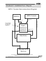
1
Installation Manual 19" Rack Part Number: MAN14R Document No: 112 September 1997 Text and Graphics: John Gavin Copyright September 1997 Ref: INSTALL-R.PM6 Cautions & Safety Requirements Safety Instructions 2 1. Read Instructions All the safety instructions should be read before the device is operated. 2. Retain Instructions The safety and operating instructions should be retained for future reference. 3. Heed Warnings All warnings on the device and in the operating instructions should be adhered to. 4. Follow Instructions All operating and use instructions should be followed. 5. Water and Moisture The device should not be used near water - for example, near bathtub, washbowl, kitchen sink, laundry tub, in a wet basement, or near a swimming pool etc. 6. Carts and Stands The device should be used with a cart or stand that is recommended by the manufacturer 7. Ventilation The device should be situated so that its location or position does not interfere with its proper ventilation. For example, the device should not be situated on a bed, soft rug, or similar surface that may block the ventilation openings; or placed in a built-in installation, such as a bookcase or cabinet that may impede the flow of air through the ventilation openings. 8. Heat The device should be situated away from heat sources such as radiator, heat registers, stoves or other appliances (including amplifiers) that produce heat. 10. Mains Power Cords and Attachment Plugs The equipment has an auto-sensing Power supply unit for sensing the mains supply circuit voltage and can be operated under various Mains Supply Voltages (100/110/220/240V). Only mains power cord and attachment plugs approved by the standards authority in the country of use should be used to connect the equipment to the alternate supply circuit voltage. A list of Recommended Mains attachment Plugs and Mains Power Cords for use in various countries throughout the world is attached. 10. Grounding or Polarization Precautions should be taken so that the grounding or polarization means of the device is not defeated. 11. Mains Power Cord Protection Mains Power cords should be routed so they are not likely to be walked on or pinched by items placed upon or against them, paying particular attention to cords at plugs, convenience receptacles, and the point where they exit from the device. Cautions & Safety Requirements Mains Plugs & Mains Power Cords The following lists the recommended Mains Plugs and Mains Leads types for use in various countries throughout the world. Mains Attachment Plugs Standards applicable for Mains Plugs Country ASTA BS1363 1984 UK BS546, 1950 India, Kenya, Nigeria, Kuwait Parts of Asia and the Far East IEC695-2-1 & NF-USE France & Belgium DIN49441 & CEE 7 Sheet VII Europe SEV Switzerland CEI23-16 Italy Mains Power Cords 3 Standards applicable for Mains Leads Country CSA22.2 No.42 & UL498 North America & Japan ASE 1011 (1959) Switzerland CEI 2316 Italy SRAF 1962 Denmark AS3112-1990, NZSS198-1967 Australia, New Zealand, Fiji, Papua New Guinea, Republic of China Fairlight Customer Support Cautions & Safety Requirements EMC Warning: The MFX 3plus Rack and MFX3plus Console conform to EMC directive 89/336/EEC standard Class A EN55022 EN50082.1.1995 And may affect domestic electronic equipment. Installers should be aware of the requirements under The EMC directive that complete installations must conform and not just the individual pieces of equipment. For information on correct procedures please refer to The following titles; Noise Reduction Techniques In Electronic Systems By Henry W .Ott EMC By Tim Williams. Caution: To reduce the risk of fire, replace only with the same manufacturer , type and rating fuse. U.L. listed or recognised fuse to be used only. Rack Fuse Rating: 125v @ 6.3 Amps 240v @ 3.15 Amps Mains Cables: All external cables are to be of U.L. listed or recognised type only. Cleaning: Do not use alcohol based cleaners on the MFX Console or Rack. A soap based solution is recommended. Ensure that the cloth is thoroughly wringed before attempting to wipe any panel or faceplates. Do not spray cleaning agents directly onto the MFX Console or Rack. Apply to a cloth and then to the unit being cleaned. 1997 by Fairlight ESP Pty Ltd All rights reserved MFX 2 and MFX 3 and MFX3plus are Trademarks of Fairlight ESP Pty Ltd The contents of this manual is copyright and cannot be reproduced, in part or in full and by any means, electronic or mechanical, including photocopying, without the written permission of Fairlight ESP Pty Ltd. 4 Contents MFX. ........................................................................................... 8 1.0 Introduction ........................................................................ 9 2.0 Unpacking ......................................................................... 10 2.1 2.2 2.3 2.4 2.5 2.6 Pre Installation Questionnaire....................................................... 10 Static .............................................................................................. 10 Unpacking Area ............................................................................. 11 Component Check List ................................................................... 11 Mainframe...................................................................................... 12 MFX Console ................................................................................. 12 3.0 Environment ..................................................................... 12 4.0 Installing The System ........................................................ 13 4.1 4.2 4.3 4.4 5.1 Rack ............................................................................................... 13 MFX Console And Monitor ........................................................... 14 External And Internal SCSI Devices .............................................. 15 External Cable Length Considerations ......................................... 15 MFX Console .................................................................................. 16 5.0 System Power-Up ............................................................. 16 5.2 Mainframe...................................................................................... 16 5.3 Possible Boot Problems & Solutions. ............................................. 18 5.3.1 Checking For Installed Software On A Drive. .................................................................... 18 5.3.2 System Fails To Boot From A Hard Drive. ......................................................................... 18 5.3.3 System Stops At MFX Picture. ............................................................................................ 19 6.0 Functional Check List ....................................................... 20 7.0 Software And Disk Information ........................................ 21 5 Fairlight Customer Support 7.1 7.2 7.3 7.4 7.5 7.5.1 Software Updates From Exabyte ..................................................... 21 Exabyte Eliant Drive ...................................................................... 22 MFX Console Software Load. ........................................................ 22 Setting The Time............................................................................. 23 Installing Internal Hard Drives ..................................................... 24 Mainframe Front ............................................................................................................ 24 7.5.2 Mainframe Rear .......................................................................... 26 7.5.3 Checking For Newly Installed SCSI Devices .............................. 27 7.6 Hard Disk And SCSI I.D................................................................. 28 7.7 Setting up SCSI Hard Drives.......................................................... 29 7.8 Setting Up Removable Media ........................................................ 30 7.9 Plug And Play Note ........................................................................ 30 7.9.1 RIO Panel ........................................................................................................................ 30 8.0 Connection & Signal Specifications.................................. 32 8.1 Analog Input / Output .................................................................... 32 8.2 Digital Input/ Output ..................................................................... 34 8.3 MFX3 Synchronisation .................................................................. 36 8.3.1 8.3.2 8.3.3 LTC And AES Synchronisation ...................................................................................... 36 Midi And Video Sync ...................................................................................................... 37 Sony 9 Pin ...................................................................................................................... 38 8.4 General Purpose Outputs And Serial Port..................................... 38 8.5 Mainframe Connections................................................................. 39 8.5.1 8.5.2 8.5.3 8.5.4 8.5.5 MFX Console Connections ............................................................................................ 39 Video Connections ......................................................................................................... 40 Printer Setup .................................................................................................................. 40 Modem Port ................................................................................................................... 41 High Speed Link Port .................................................................................................... 41 8.6 Analog Performance ...................................................................... 43 9.0 Printer Information ........................................................... 44 9.1 Serial Data & Connection Information ......................................... 44 9.2 Primax Bidirectional Interface Converter ...................................... 45 10.0 Hints and Suggestions ..................................................... 46 11.0 What To Do If Your System Has A Problem .................. 47 6 11.1 Under Warranty ............................................................................ 47 11.2 Out Of Warranty ........................................................................... 47 11.3 General ......................................................................................... 47 Attachment 1 Card Placement Guide ..................................... 48 Attachment 2 ESPDCC Addressing........................................ 49 Attachment 3 Notes Page ....................................................... 50 Intentionally Blank ................................................................................ 50 Attachment 4 Warranty Policy ............................................... 51 Attachment 5 Registration Form............................................. 55 Attachment 6 Quality Issue Notification Form ....................... 57 Attachment 7 System Fault Log ............................................. 58 Attachment 8 Preinstallation Questionnaire ........................... 59 Attachment 9 Installation Power Diagram............................. 61 Attachment 10 Printer Tips ..................................................... 62 7 Fairlight Customer Support MFX. Courtesy Todd AO 8 1.0 Introduction Congratulations on choosing the Fairlight MFX3plus Digital Audio Editing system. Fairlight’s MFX3plus system offers the ultimate in speed and ease for recording and editing audio, as well as all the software you need to manage your work flow, your sound libraries and your storage resources. Like all Fairlight audio products, MFX3plus has been designed from the ground up to do audio. It is a multiprocessor architecture that uses a true multitasking, real time Disk Operating System, designed specifically for the needs of large digital audio files and real time graphical display of the audio. This is integrated into a multi-layered “object-based ” editing environment that is uniquely fast and easy to use, with video machine control built into the editing functionality, virtually eliminating the need to type in time codes. MFX3plus has a fine pedigree. It is the eighth model of Digital Audio Workstation from the company that introduced the first commercial system capable of playing and editing digital audio waveforms, in the mid seventies. MFX3plus is Fairlight’s sixth model of disk recorder and is operationally and architecturally distinct from any other disk based product, mainly due to major proprietary features in both hardware and software. An ongoing commitment to development will continue to keep MFX3plus at the leading edge of audio production tools, while maintaining the richness of features and friendliness of its user interface. With a clear direction towards the all digital world of the future, MFX3plus is today’s solution for audio post, during the 90’s transition from analog to digital and beyond. Fairlight has shown time and again the value of an open architecture to protect the investment of it’s users. This has allowed the continued enhancement of the basic platform to include the latest in audio technology with minimal cost, disruption and re-education. The MFX3plus system has been designed with a great deal of attention to reliability. To ensure that the operation of your system is flawless from the first session please follow the installation directions outlined in this manual. The scope of the work involved is such that it should be performed by a suitably technically qualified person, under anti static conditions. If you have not received prior training on the correct installation of the MFX3plus system it is recommended that you contact you nearest distributor to arrange installation. Incorrect installation will void the conditions of warranty and lead to possible delays before the system is up and running. Customers should be aware that MFX2 files can be imported into MFX 3plus, however the reverse is not possible. Thus if the facility has a number of systems it is advisable that upgrades be purchased for any existing MFX2 systems. References will be made to some options available on the MFX3plus which may not pertain to your system. Your investment in Fairlight puts you at the leading edge of productivity, now and in the future. 9 Fairlight Customer Support 2.0 Unpacking 2.1 Pre Installation Questionnaire Please ensure the pre-installation questionnaire has been filled out and returned to your dealer, prior to commencement of the system installation. For copy see Attachment 7. 2.2 Static Please take note that all Fairlight manufactured electronic modules are static sensitive and should be handled under anti static conditions. When working on a system always ensure that you have an anti static lead connected and that the system is connected to ground through an earth lead. Never work on the system while powered up unless you are authorised by Fairlight to do so. As a matter of practice always touch the external chassis of the system before opening the front panel or going to disconnect cables. If cards are not handled under anti static procedures your machine may sustain damage which could either cause a complete failure or may cause intermittent crashes and subsequential system failure. When handling cards please ensure that they are placed in anti static bags when not in the system. For shipment purposes electronic modules should be placed in an anti static bag and then suitably surrounded with loose packaging materials in a solid card board box. Cards shipped to Fairlight without the correct anti static packaging will have their warranty voided. If you have any enquiries on this matter please feel free to contact your local Fairlight office. Finally, we at Fairlight take pride in the product we design, build and support. Through supporting system in a quality manner we have been able to keep CMI systems running for near on 20 years, and we look forward to doing so for your system. Connecting an antistatic strap 10 2.3 Unpacking Area It is advisable that before any installation work is attempted that the system be unpacked and the contents thereof verified. A sizeable area approximately 3 meters square should be suitable. Using the basic packing list attached record the items you have received and the serial number where applicable. This will both help you when you have to make an enquiry ( having the relevant details logged in your Installation manual ), and in the event of a packing omission. At this stage do not power up the system, nor remove electronic modules from the system, as damage may occur if not handled correctly. 2.4 Component Check List The following is a generic list of items that are shipped with a typical system. It is not meant to reflect all systems nor all possibilities, however, all items are required if the system is to be commissioned. Please place a tick in this manual against the items you have received. Please tick items received. Item Brief Description Qty Received √ Mainframe MFX Console MFX Power Supply User Manual Installation Manual Mouse MFX Cable Video Cable 9 Pin Cable D Connector Set T Shirt – White T Shirt – Black Registration Form Power Cable SCSI Terminator Exabyte Tape Containing Digital & Analog Cards User Interface External Power Supply Operational Outline Guide To Installation Mouse Console Cable 10m Video Extension Cable Sony Machine Control Cable 5m Digital & Analog Connector Set Details Of Shipped System IEC Power Cable SCSI Buss Termination Software Installation Tape 1 1 1 1 1 1 1 1 1 1 2 2 1 1 1 1 If you have not received all of the above items please contact your dealer immediately and the item will be dispatched with utmost urgency. 11 Fairlight Customer Support 2.5 Mainframe The mainframe is packed in the largest of the two boxes supplied with each new system. It is typically packed in a brown, cardboard box measuring 500 * 600 * 500 mm. As the mainframe is quite large and heavy it is strongly recommended that it is removed from the box and packing by two persons. Avoid sharp knocks to the unit as damage may occur to the electronic modules contained inside. 2.6 MFX Console The MFX console is packed in a white box measuring 650 * 470 * 380 mm. All accessories and cables are normally packed in this box with the MFX console itself, such as the video cable, the MFX cable etc. 3.0 Environment The system is designed to be operated in a clean air-conditioned environment. Generally, an area comfortable for people ( 19°C - 20°C ) should be suitable. The rack mounted units and disk drives, use fans for ventilation. Users may find it desirable to install these units away from the operator/MFX console location. Note that cable lengths, as detailed in "External Cables" should be taken into account when planning the installation. Make sure that the rack units can access cool air through the opening on the back near the base, and expel warm air from the fans near the top. As with all computer systems, the Fairlight will operate more reliably if static generating floor coverings are avoided. Do not fit unit into closed Rack except where ducted air is forced through the Rack. Do not run Rack whilst it is on the ground as it will accumulate dust which will eventually cause a failure which will not be covered by Warranty. The mainframe unit is normally installed in a suitable 19" rack which is at least 600 mm deep, or has an open back section. It is recommended that external hard drives be mounted on a rack tray, above or below the mainframe unit. Please Avoid: 12 Fitting mainframe where air circulation will be restricted. Installing mainframe close to heat sources. Installing in dusty or damp area. Installing in unstable situation or area subject to vibration. Installing in area with strong magnetic or electric fields. 4.0 Installing The System The following section covers the installation of the mainframe and console units and the associated interconnections and cables. A block diagram is included for reference purposes ( Attachment ). 4.1 Rack The mainframe unit, takes up 8 RU, when fitted into a 19” rack. It operates from either 100-120v or 200-250v, 50-60Hz with the mains inputs being auto- switching, as such there are no switches to be set. At least two people are required to fit the Mainframe into a 19” rack as the unit is quite heavy. If available it is suggested that a third person be made available for the initial fitment into the rack, such that a person can guide the Mainframe into the rack, from the rear. The Mainframe should be fitted such that there are no restriction to the ventilation, at the rear of the unit. If external SCSI devices are to be connected it is recommended that these be placed on a rack tray above or below the Mainframe. It should be noted that typically the Mainframe unit is fitted with a boot drive with SCSI I.D. “ 0 ”( although the boot drive can be at any ID ). As the Mainframe uses fans for its forced ventilation system, these generate an amount of ambient noise. The Mainframe should be located in an air conditioned machine room away from the studio and other heat generating equipment. 13 1. Install Mainframe into 19” Rack unit. ( Requires removal of front panel ) 2. Ensure that the mains switch is in the off position, and then connect the input power lead. 3. Connect the printer cable to the 9 Pin D connector on the RIO panel of the Mainframe. The connector is marked as “Modem”. 4. Remove the front dress panel by undoing the four thumb screws. Fairlight Customer Support 5. Using an anti static strap connect yourself to the mainframe chassis. 6. Using a small Phillips screwdriver open up the front RFI panel and ensure that all the cards are firmly seated into their respective slots by pushing on the card ears at the top and bottom of each card. 7. Replace the RFI panel and front panel on the mainframe. 8. Connect the 15 way D connector of the Video cable to the “ Video Monitor ” connector on the RIO panel of the Mainframe. 9. Connect the MFX Console cable to the Mainframe at the 24 way Centronics connector located on the Sync I/O module at the rear left of the Mainframe. 10. Connect any external SCSI drives and ensure that the last device is terminated. Ensure that the SCSI I.D.’s are not in conflict with each other. 11. Connect all Sync input cables such as LTC, Word clock, Black burst etc. 12. Connect all digital/audio input/output cables 4.2 MFX Console And Monitor 14 1. Place the Console at a suitable location close to the mixing desk. 2. Connect the MFX cable to the 37 Pin D connector on the rear of the Console. 3. Connect the mouse to the 9 Pin D connector on the rear of the Console. Please note that the mouse is no longer required. By holding the shift key when selecting “X-Point” it toggles between horizontal and vertical adjustment of the crossfade parameters. 4. Connect the MFX Console power supply to the MFX Console and then connect the mains power to the MFX Console power supply . 5. Once all connections have been made to the MFX Console, it can be powered up safely, at the power board or wall outlet. Note: To avoid noise on the system and earthing problems, it is advisable that the mains source for the Mainframe also be the mains source for the MFX Console. 4.3 External And Internal SCSI Devices The Mainframe unit is designed to accept one 3.5” drive in the rear section. Typically the boot hard drive will be installed into the Mainframe itself, inside the rear rightmost ( RIO ) panel. When connecting external devices ensure that their SCSI ID does not conflict with devices fitted into the Mainframe. There is a SCSI ID switch on the rear SCSI panel for changing the SCSI ID of the internal boot drive. It is possible for Fairlight to install 3 * 3.5” drives in the front of the Mainframe however these drives should be ordered as installed when placing an order with Fairlight. Typically Exabyte drives should be set to ID “ 5 ” when connected to the Fairlight. It is recommended that a rack tray be fitted either above or below the Mainframe to hold external SCSI devices. The last device on the chain should be terminated with all other devices being looped through. Optical devices when attached should be set to ID “ 3 ”. 4.4 External Cable Length Considerations The following table indicates the maximum length of cables useable. Cable Name Recommended Maximum 15 Video Cable The length of this cable is monitor dependant. MFX Console Cable 10 metres 20 metres Monitor Dependent 20 metres 9 Pin Control Cable 5 metres 30 metres External SCSI Cables 1 metre, each cable 4 metres total length Fairlight Customer Support 10 metres 5.0 System Power-Up Before you switch on power. Check that all cables are firmly seated in their connectors. Do not connect cables or SCSI devices while system is powered up. 5.1 MFX Console Once the mouse and MFX cables have been connected the MFX Console can be powered up. Turn on the power switch ( at the source ) and the Console will boot up. The green LC display to the top right of the Console should display zero’s on the top display ( right hand side ) and the lower display should display “MFX3” with the software revision beneath. If the LCD does not light up ensure that the power is turned on at the source. If the Console display lights up, and an error message is displayed, it will be necessary to download the software to the Console as described under “ Software And Disk Information ”. 5.2 Mainframe The powering up of the Mainframe is the most critical part of the installation exercise. By spending extra time at this stage, before power is applied, checking all connections and SCSI devices, the potential for damage to the system will be reduced. 1. 2. 3. 4. 5. 16 Ensure all SCSI cables and terminators are connected. Power up all SCSI devices. Verify monitor cable is connected and thence power up the monitor. Ensure all Sync Input/Output cables are connected and secure. Turn down the master faders on the mixing console. 6. Ensure all digital and analog Input / Output cables are connected and secure. 7. Ensure MFX Console cable is connected and secure. 8. Ensure 9 pin control cable is connected and secure. 9. Power up the Mainframe via the switch on the front panel. 10. Power up the MFX Console, if not already powered up. At this point the system is booting up if all has gone to plan. Initially you will observe a gray and blue text screen, containing system configuration information. The system will continue booting until the Disk recorder is loaded. This will take approximately 29 seconds. Excellent ! Typical Boot Screen showing 0 through 5 ESPDCC's fitted, ie 24 Channels If a problem is encountered and the system does not boot up you should take note of the boot screen details as these will prove useful if it is necessary to contact Fairlight. If the problem is related to the SCSI devices you may see the following; Boot Screen indicating boot device found at ID 3. In the above picture it is apparent that the system cannot find a boot drive and has scanned positions 0 through 2 without success. If no boot drive is found after passing through ID 6 the system will reset itself and re scan the SCSI buss. If this occurs check all SCSI devices, termination and cables as there may be a simple problem in this area. In this example the system has found a boot drive at ID 3. 17 Fairlight Customer Support 5.3 Possible Boot Problems & Solutions. 5.3.1 Checking For Installed Software On A Drive. The following procedure will allow you to verify that software has been installed on a Drive with SCSI I.D. XX, where XX is the number of the Drive you wish to check, i.e. /SCXX. 1. 2. 3. 4. 5. 6. 7. 8. 9. 10. Power up the system as per normal. Press the < Space Bar > as soon as possible to bring up the ROM Menu. At the prompt type “ROM” then press < Return > The system will boot to the Wave Exec Rom and allow you to perform a limited set of commands. Type “ DIR /SCXX ” where XX is the SCSI I.D. of the drive you believe has software installed. You should see the following. The upper case indicates directories and the lower case indicates files; CMDS ETC SYS USR dd.bf machine release.list startup.user startup.osk30 14_1_13.GZ startup.dev The above files are not in order and will vary in order depending on the system . The directories should always bee present on all systems. The software version as indicated is an example. Software files are in the format 14_X_XX.GX. As such you may have a different version or even multiple versions. This is not a problem. If none of the files nor directories exist then software has not been installed on the drive. Install software from Exabyte or another drive as explained in this manual. 5.3.2 System Fails To Boot From A Hard Drive. If your system fails to boot from a hard drive which you believe has software on it, the following procedure may be of assistance. 1. 2. 3. 4. 5. 6. 18 Reboot the system and press the < Space Bar > as soon as is possible. You should see a small menu with the following prompt; “ Select a boot method from the above menu: ” Type “SCANTS” then press < Return > Check that the drive you are attempting to boot from is detected. If detected there is probably a boot sector problem on the Drive or the Drive may not have software installed. If not detected, then check all SCSI connections and that the drive is powered up. 5.3.3 System Stops At MFX Picture. If after powering up your new system it appears to stop at the point where the MFX picture is displayed the following should correct the problem. 1. 2. 3. 4. 5. 6. Type “QUIT” < Return > Answer “Y” to the question. Type “MFXLOAD” < Return > Allow the Mainframe to load software into the MFX Console. The Console will reset itself when finished. Reboot the system by typing “RESTART” < Return > The system should now boot through to the Disk Recorder. If the above procedure fails please press the < Blue > key and then the < ESC > key. Take note of the last 6 lines and with a brief explanation of the problem, fax to you local Distributor or Fairlight office for further assistance. 19 Fairlight Customer Support 6.0 Functional Check List Once the system is running you will want to verify that it is functioning correctly, the following tests should be done before the system is given a final OK : 6.1 All channels audio in/out, distortion at 32k, 44K1, 48K( 0.006% or better ) 6.2 All channels digital in/out, distortion at 32K, 44K1, 48K ( As per source) 6.3 All channels audio out, noise floor ( -89dB or better ) 6.4 All channels digital out, noise floor ( -110dB or better ) 6.5 All channels record ( 15 minute test ) 6.6 All channels playback ( 15 minute test ) 6.7 DC offset on audio out’s 6.8 Verify WCLK synchronisation mode 6.9 Verify Video synchronisation mode 6.10 Verify LTC synchronisation on Port A 6.11 Verify LTC synchronisation on Port B 6.12 Verify 9pin control on Port A 6.13 Verify write to each SCSI device respectively 6.14 Perform MFX Console software load 6.15 Backup small project to backup device and restore 6.17 Reboot system 4 times with 5 minute break between boots 6.18 Verify that monitor has been adjusted to display full screen 6.19 Set the correct time for your region using “Setime” 20 ( M1 button on ) 7.0 Software And Disk Information The following information is for reference only. New systems have all operating system software loaded and should be operational at power up. The system will boot from the hard disk provided (drive zero is /SC00). If you have any questions regarding software or hard disks, please contact your dealer. 7.1 Software Updates From Exabyte To update software from Exabyte when no Rev 14 drives are available; 1. Ensure that an Exabyte drive is connected and set to ID 5 2. Power up the Exabyte drive 3. Place the Exabyte software tape in the drive. 4. Power up the Mainframe. 5. Press the < Space Bar > immediately on powering up the system. You may need to press the < Space Bar > a few times. The aim is to stop the system booting from a hard drive if one is connected. 6. The displayed prompt is “ Select a boot method from above menu: ”. 7. Type “ ROM ” < Return > to boot to Wave Exec Rom. 8. Type “ Upgrade -T ” < Return>. This tells the system to boot from the Exabyte at ID 5. Follow the procedure as appears on the screen. You will be asked if you want to reformat the drive. Answer NO to this if there are projects you require on the drive. Alternative method if you already have Rev 14 software on an existing connected drive. 1. Boot the system and quit to the Shell from the Project page. 2. The displayed prompt is “ # ”. 3. Type “ Upgrade ” < Return >. 4. Follow the prompts and select the drive you wish to install software to. 5. Follow the steps as they appear on the screen again noting that you do not need to reformat the drive when asked during the process, particularly if you have existing work you require. It is recommended that if you are installing software for the first time to a drive, that you ensure that there are no required projects on the drive so that the drive can be reformatted. 21 Fairlight Customer Support 7.2 Exabyte Eliant Drive Ensure unit is powered up and tape is inserted before powering up Mainframe All software copies are created on 8500 units to ensure compatibility with 8500, 8505 and 8700, 8705 & Eliant units. 7.3 MFX Console Software Load. ( For reference only. A system software update will load the MFX Console software ) To reload software into the MFX Console the following procedure should be used; 1. Allow system to boot to the Project page. If system does not boot to this point press < CNTRL & Q > during the boot process. 2. Type MFXLOAD and press < Return >. 3. The system will automatically load software to the MFX Console and reset the Console when finished. On releasing " Blue " and " + " and " - " 22 7.4 Setting The Time To change the time and date information: 1. Allow system to boot to the Project page. 2. Type “ # ” and press < Return > 3. Type “ Setime ” and press < Return > 4. Enter the time in the format displayed with correct placement of Colons and forward slashes etc. 5. Press <CNTRL > and < RETURN >. The clock should now show the correct time and date 23 Fairlight Customer Support 7.5 Installing Internal Hard Drives With Rev 14 metalwork and above it is possible to install hard drives in the front and rear of the Mainframe. The major improvements over older version of metalwork are that a fan has been added to increase cooling and the drive mounting is now horizontal. Fairlight has a policy of mounting hard drives horizontal whenever possible, as research has suggested that vertical mounting may contribute to earlier than normal drive failure. 7.5.1 Mainframe Front Part 1 To install hard drives in the front of the Mainframe please follow these steps; 1. 2. 3. 4. Power down the system and leave the power lead connected. Remove the front dress panel via the four thumb screws. Remove the front screen to gain access to the drive and card area. Remove the four screws holding in the drive mount bracket. This is to the left of the Mainframe. 5. Remove the drive mounting bracket from the system and place on suitable workbench. Drive Bracket Removed From Mainframe Part 2 1. As per the procedure outlined in “ Setting Up SCSI Hard Drives ” check that the Hard drives to be mounted are set up correctly. 2. Taking care to note the orientation of the SCSI cable in the front of the Mainframe, mount the drives into the bracket. 24 Part 3 1. Connect the SCSI ID cable as per the manufacturers instructions. Ensure that SCSI ID’s do not conflict with each other or existing drives connected to the system. A drive may not be seen if its ID conflicts with another SCSI device. 2. Re install the bracket assembly back into the Mainframe ensuring that you have connected power leads and the 50 way SCSI lead to all fitted drives. 3. Before reinstalling the screen and the front dress panel power up the system and determine that all your newly fitted and existing drives are detected. SCSI ID Cable Connected Below we see the completed assembly with power, SCSI and SCSI ID cables connected. Again, please ensure that no two SCSI ID’s are the same. That the SCSI drives are not internally terminated. That the drives termination power is configured as being, from the buss. Installed And Tested 25 Fairlight Customer Support 7.5.2 Mainframe Rear Part 1 1. Power down the system and leave the power lead connected. 2. Remove the rear RIO panel by removing the six thumb screws. 3. As the SCSI cable is attached to the panel you will not be able to remove it fully from the Mainframe. Bare Bracket - Rear RIO Panel Part 2 1. 2. 3. 4. 5. 6. 7. Check that the drive you are about to install has been set up correctly, as per “ Setting Up SCSI Hard Drives ”. Mount the drive in the bracket with the appropriate screws. Mount the drive to the rear of the bracket as much as possible to maximise clearance when fitted into the Mainframe. Take note of the orientation of the SCSI cable such that you do not need to twist it when connecting to the drive. Attach the SCSI ID cable and power cable. Mount the complete assembly back into the Mainframe. Check the SCSI ID of the newly mounted drive for conflicts with other SCSI devices on the SCSI Buss. Typically this should be set to I.D. 0, i.e. Boot Drive. Test system for correct detection of the newly mounted hard drive. Internal View Of SCSI Assembly When Fitted 26 7.5.3 Checking For Newly Installed SCSI Devices Once you have mounted all external and internal SCSI devices, the following will aid you in determining if they are all detected. 1. 2. 3. 4. 5. 6. 7. 8. 27 Ensure that the Mainframe is completely re-assembled and that there are no loose cables. Power up the Mainframe and Console. Press the SPACE BAR once a gray display is seen. If you miss the time window in which the Space bar must be pressed, simply reboot and try again. The displayed prompt is “ Select a boot method from the above menu: ”. From the prompt type “ SCANTS ” < RETURN >. Observe that all SCSI devices are detected. You may need to run this command a couple of times as some drives are much slower to boot than the MFX. If a SCSI device is not seen, power down the system and check all SCSI ID’s and that the SCSI and power cables are connected. Fairlight Customer Support 7.6 Hard Disk And SCSI I.D. A system must have at least one hard disk. For the disk recorder application (MDR), this disk must be a Fairlight approved drive and installed by your Fairlight dealer. Warranty may be voided if incorrect peripheral installation causes system failure. A maximum of 7 storage devices may be attached to the SCSI bus. SCSI I.D.'s can be 0 through to 6. SCSI I.D. 7 is reserved for the Turbo SCSI card. All cabling to SCSI devices must be kept as short as possible and have a SCSI terminator plugged into the last drive in the chain. Some disks have SCSI terminating resistors in place and this should be checked and resistors removed when extra disks are being added to the system. Lower transfer rates and SCSI errors will result if this bus is not correctly terminated. Set the SCSI I.D. of the device to the next available address. On some disks this will be an external switch with a number indicating the SCSI I.D. or you may have to set some jumpers on the disk interface card attached to the disk. Please refer to the specific disk manual for this information. The SCSI I.D. can be a number between 1 and 6. As a matter of consistency we would use even I.D. numbers for disks and odd I.D. numbers for backup/ removable media devices. The default SCSI I.D. for an Exabyte tape backup device must be SCSI I.D. 5 (/SC50). Having set the SCSI I.D. and checked all connections, turn the system ON. During the boot process the system will interrogate the SCSI bus to ascertain what devices are connected. This information will be displayed on the screen. If the SCSI ID and device information does not appear, check all connections and address information. When adding a hard disk to the system you must format the disk for Fairlight operation. This can be done by referring to the procedure “ Setting Up SCSI Hard Drives ”. It should be noted that the maximum length of external SCSI cables must be less than 4 meters. This includes the approximate 1/3 meter internal to each external box. We recommend that the boot drive is set to I.D. 0 Set the Exabyte I.D. to I.D. 5 only. Set Optical drives to I.D. three. This is the standard and allows easier debugging when a problem occurs. Ensure that only last device on SCSI chain is terminated. Drives should be set up with SCSI termination power from SCSI BUSS and SCSI termination disabled 28 7.7 Setting up SCSI Hard Drives ( Only necessary for a new drive or one that generates CRC errors) MFX Rev 14 drives can be low level formatted on a standard SCSI PC. Once the drive has been formatted, running the Diskinit command on the drive via the MFX will allow correct operation. Alternatively, with most drives just running the Diskinit command as follows will work successfully; Exit the Disk Recorder by typing 'QUIT' < Return > 'Y' The displayed prompt is “ # ”. DISKINIT /SCX0 –V=1024 –C=128 < RETURN >. (Where 'X' is the SCSI address of the device) If a new boot drive is attached to the system the DISKINIT command can be run from system ROM, i.e. you do not need to boot from a drive with software. The following procedure outlines the steps; 1. 2. 3. 4. 5. 6. 7. Connect the drive that requires set-up. Power up the MFX. Press the SPACE BAR immediately on power up. The displayed prompt is “ Select a boot method from the above menu: ”. Type “ ROM ” < Return >. This will cause the system to boot from Rom. Type the Diskinit command as outlined above. The drive will be set up for software. If after you have completed the above, you wish to install software from Exabyte complete the following; 1. 2. 3. 4. 5. Place the Exabyte tape in the Exabyte drive. The displayed prompt is “#”. Type “ UPGRADE –T ” < Return >. Follow the prompts and select the desired drive. Software will be installed and the system will reboot. Before connecting the drive to a system ensure that there are no SCSI ID conflicts, i.e. that a drive is not already connected with the ID of the drive you are about to connect. Drives being set-up to be used on the MFX3plus should have all internal termination’s and termination power turned off. In MFX3plus applications the termination power is supplied by the MFX3plus. Termination is achieved by use of external terminators on the last device on the chain. SCSI busses should be terminated at the beginning and end of the chain only. In MFX3plus the SCSI card is supplied terminated and as such you only need to terminate the last attached drive. 29 Fairlight Customer Support 7.8 Setting Up Removable Media To set up optical drives for use on the MFX3plus it is not necessary to format the media. All that is required is that the following command be run on the media; DISKINIT /SCX0 –C=128 –V=1024 –Z –N=”Name” ( eg Boot ) This command must be run from the shell so you will need to quit from the disk recorder to the shell. When media is not in use it is strongly recommended that the media is ejected from the drive to ensure that the media is not deteriorated due to the level of heat in the drive itself. Keep media away from strong magnetic fields and direct sunlight. 7.9 Plug And Play Note The MFX3plus system automatically detects new SCSI devices. For example if an Optical drive is connected at boot up and the media is not present the device will be seen on the Project page, however it will indicate no media. On placing a suitable formatted media in the drive the device will become available for use. Hard drives will also be automatically detected if they are installed correctly in plug and play assemblies such as the Micropolis unit. Please avoid connecting external devices by breaking the SCSI chain while the system is running as it can either crash the system or if a project is open lead to project corruption 7.9.1 Reset Switch Modem Port Graphics Port High Speed Link Port 30 RIO Panel SCSI I.D. Switch SCSI Port 31 Fairlight Customer Support 8.0 Connection & Signal Specifications 8.1 Analog Input / Output Inputs Connectors Input Input level Input sensitivity Input attenuation range Input impedance Pin 1 Pin 2 Pin 3 Pin 4 Pin 5 Pin 6 Pin 7 Pin 8 Pin 9 Pin 10 Pin 11 Pin 12 Pin 13 Pin 14 Pin 15 1x 15 pin D-mini Female Balanced +22 dBu max -10 dBu / +4 dBu switched 14 dB to -99 dB > 10K ohm Frame Ground IN 1 GND IN 2+ IN 2IN 3 GND IN 4+ IN 4NC IN 1+ IN 1IN 2 GND IN 3+ IN 3IN 4 GND NC Audio input cables should be wired using male connectors as the MFX input is a female connector as seen below. View of analog in connector Pin 1 32 Outputs Connectors Output Output Level Output impedance Output load Pin 1 Pin 2 Pin 3 Pin 4 Pin 5 Pin 6 Pin 7 Pin 8 Pin 9 Pin 10 Pin 11 Pin 12 Pin 13 Pin 14 Pin 15 1x 15 Pin D-mini Male Electronic Balanced Differential +22 dBu max at 0 dB digital full scale (nominal +4 dBu) < 55 ohms 600 ohms minimum Frame GND OUT 1 GND OUT 2 + OUT 2 OUT 3 GND OUT 4 + OUT 4 NC OUT 1 + OUT 1 OUT 2 GND OUT 3 + OUT 3 OUT 4 GND NC Audio output cables should be wired using female connectors as the MFX output is a male connector as seen below. View of analog out connector Pin 1 33 Fairlight Customer Support 8.2 Digital Input/ Output AES / EBU INPUT Connector Channels Sample Rates Input Type Input Level 37 way D-mini Female 2 x Stereo pairs per I/O Module 44.1 KHz , 48.0 KHz, 32 KHz, 44.056 KHz 200 mv Differential Minimum +22 dBu Peak Pin 17 Pin 18 Pin 19 Pin 35 Pin 36 Pin 37 AES IN 1 GND AES IN 2AES IN 2+ AES IN 1AES IN 1+ AES IN 2 GND AES / EBU OUTPUT Connector Channels Sample Rates Output level 37 way D-mini Female 2 x Stereo pairs per I/O Module 44.1 KHz, 48 KHz, 32 KHz, 44.056 KHZ 4.3v Minimum Pin 14 Pin 15 Pin 16 Pin 32 Pin 33 Pin 34 AES OUT 1 GND AES OUT 1AES OUT 1+ AES OUT 2AES OUT 2+ AES OUT 2 GND SPDIF INPUT 34 Connector Channels Sample Rates Input level 37 way D-mini Female 2 x Stereo pairs per I/O Module 44.1 KHz, 48 KHz, 32 KHz, 44.056 KHz 200 mv minimum Pin 12 Pin 13 Pin 30 Pin 31 SPDIF IN 1 SPDIF IN 2 SPDIF IN 1 GND SPDIF IN 2 GND SPDIF OUTPUT Connector Channels Sample Rates Output Level 37 way D-mini Female 2 Stereo pairs per I/O Module 44.1 KHz, 48 KHz, 32 KHz, 44.056 KHz 0.5v p-p Pin 10 Pin 11 Pin 28 Pin 29 SPDIF OUT 1 SPDIF OUT 2 SPDIF OUT 1 GND SPDIF OUT 2 GND YAMAHA Connector Channels Sample Rates Output Level 37 way D-mini Female 2 44.1 KHz, 48 KHz, 32 KHz, 44.056 KHz 3.3v p-p differential Pin 7 Pin 8 Pin 9 Pin 25 Pin 26 Pin 27 Yamaha Y2 DATA 2+ Yamaha Y2 DATA 1+ Yamaha Y2 WCLK + Yamaha Y2 DATA 2Yamaha Y2 DATA 1Yamaha Y2 WCLK - GROUND & NO CONNECTIONS Connector 37 way D-mini Female Pin 1 Pin 2 Pin 3 Pin 4 Pin 5 Pin 6 Pin 20 Pin 21 Pin 22 Pin 23 Pin 24 GND NC NC NC NC NC NC NC NC NC NC View of digital input/output connector Pin 1 35 Fairlight Customer Support Use male connector when assembling cable looms. 8.3 MFX3 Synchronisation 8.3.1 LTC And AES Synchronisation LTC IN A XLR Female LTC input A -20 dBm to +10 dBm Pin 1 Pin 2 Pin 3 GND IN + IN - LTC IN B XLR Female LTC input B -20 dBm to +10 dBm Pin 1 Pin 2 Pin 3 GND IN + IN - IMPORTANT NOTE: 36 Unbalanced loads should be connected to Pin 1 Ground and Pin 2 Signal. Pin 3 should not be connected to ground. LTC OUT XLR Male LTC output 0 dBm Pin 1 Pin 2 Pin 3 GND OUT+ OUT - AES SYNC IN XLR Female DARS sync input Pin 1 Pin 2 Pin 3 GND IN + IN- AES SYNC OUT XLR Male DARS sync output Pin 1 Pin 2 Pin 3 GND OUT + OUT - 8.3.2 Midi And Video Sync MIDI IN A 5 pin DIN 180 MIDI IN B 5 pin DIN 180 Pin 1 Pin 2 Pin 3 Pin 4 Pin 5 Pin 1 Pin 2 Pin 3 Pin 4 Pin 5 NC NC NC IN+ IN- NC NC NC IN+ IN- MIDI OUT A 5 pin DIN 180 MIDI OUT B 5 pin DIN 180 Pin 1 Pin 2 Pin 3 Pin 4 Pin 5 Pin 1 Pin 2 Pin 3 Pin 4 Pin 5 NC GND NC OUT+ OUT- VIDEO IN BNC NC GND NC OUT+ OUT- Video sync input 1v p-p 75 Ohms terminated SONY AND MULTI MFX MFX IN and MFX OUT are for chaining multiple MFX systems using pin-to-pin cable. This function has not been implemented in software due to it’s obsolescence through networking MFX OUT MFX IN DB15 VGA Female DB15 VGA Female Pin 1 Pin 2 Pin 3 Pin 4 Pin 5 Pin 6 Pin 7 Pin 8 Pin 9 Pin 10 Pin 11 Pin 12 Pin 13 Pin 14 Pin 15 37 Fairlight Customer Support GND TXSRXSZTPSWCLKSNC TXS+ RXM+ ZTPS+ WCLKS+ NC NC NC NC NC Pin 1 Pin 2 Pin 3 Pin 4 Pin 5 Pin 6 Pin 7 Pin 8 Pin 9 Pin 10 Pin 11 Pin 12 Pin 13 Pin 14 Pin 15 GND RXMTXMZTPMWCLKMNC RXM+ TXM+ ZTPM+ WCLKM+ NC NC NC NC NC 8.3.3 Sony 9 Pin SONY A DB9 Male Pin 1 Pin 2 Pin 3 Pin 4 Pin 5 Pin 6 Pin 7 Pin 8 Pin 9 SONY B DB9 Male GND TXRX+ GND Frame sync GND TX+ RXGND Pin 1 Pin 2 Pin 3 Pin 4 Pin 5 Pin 6 Pin 7 Pin 8 Pin 9 GND TXRX+ GND Frame sync GND TX+ RXGND WCLK IN BNC word clock sync TTL input 1 HCMOS load WCLK OUT BNC word clock sync TTL output max 1 TTL load VITC IN BNC 1v p-p, 75 Ohms terminated SONY SLAVE DB9 Female Pin 1 Pin 2 Pin 3 Pin 4 Pin 5 Pin 6 Pin 7 Pin 8 Pin 9 GND RXTX+ GND Frame sync GND RX+ TXGND 8.4 General Purpose Outputs And Serial Port 38 GPO DB9 Male General Purpose Outputs Open Collector 30v max, 40 mA max Pin 1 Pin 2 Pin 3 Pin 4 Pin 5 Pin 6 Pin 7 Pin 8 Pin 9 GND GPO1 GPO2 GPO3 GPO4 GPO5 GPO6 GPO7 GPO8 SERIAL DB9 Male Serial Port RS232 Pin 1 Pin 2 Pin 3 Pin 4 Pin 5 Pin 6 Pin 7 Pin 8 Pin 9 NC RX TX DTR GND DSR RTS CTS NC ( RI ) ETHERNET 8 pin RJ45 socket Implementation In Progress 8.5 Mainframe Connections 8.5.1 MFX Console Connections D37 Connector Female. Male on cable. Pin 1 Pin 2 Pin 3 Pin 4 Pin 5 Pin 6 Pin 7 Pin 8 Pin 9 Pin 10 Pin 11 Pin 12 Pin 13 Pin 14 Pin 15 Pin 16 Pin 17 Pin 18 Pin 19 Gnd Gnd NC NC NC MFX data KBD232 Midi In D + Midi Out D + Key + TX422 + RX422 + SCSI INTERFACE 50 way Centronics 39 Fairlight Customer Support Pin 20 Pin 21 Pin 22 Pin 23 Pin 24 Pin 25 Pin 26 Pin 27 Pin 28 Pin 29 Pin 30 Pin 31 Pin 32 Pin 33 Pin 34 Pin 35 Pin 36 Pin 37 Single ended SCSI port CMI Data Midi In D MIDI Out D422 CTS Key TX422 TX422 Gnd EDL Comms Rx EDL Comms Tx 8.5.2 Video Connections VIDEO MONITOR DB15 VGA Female Pin 1 Pin 2 Pin 3 Pin 4 Pin 5 Pin 6 Pin 7 Pin 8 Pin 9 Pin 10 Pin 11 Pin 12 Pin 13 Pin 14 Pin 15 8.5.3 VGA standard video 512 x 512 resolution Hsync 45.8kHz Vsync 75Hz RED GREEN BLUE GND GND GND GND GND NC GND GND NC HSYNC VSYNC NC Printer Setup Baud-Rate 38K4 or 9K6, 8 bits, 1 stop bit, No Parity; Xon/Xoff handshake. SERIAL INPUT printers ONLY. EPSON ESC/P - 9 pin protocol or ESC/P2 - 24 pin protocol (preferred). A suitable printer is the Canon BJ-330 fitted with the BJIF-3020 serial interface card. Fairlight RS232 Female Pin Name 1 2 3 4 5 6 7 8 9 N/C RxD TxD DTR Gnd DSR RTS CTS N/C Printer ( eg. EPSON SQ1170 ) BJ-330 D25 Male Pin Name 2 3 6 7 20 5 4 TxD RxD DSR Gnd DTR CTS RTS All other pins unused. To change the printer configuration, type <esc> 'S' from the Disk Recorder. Change the printer parameters with the mouse. 40 8.5.4 Modem Port 9 Pin D Female Serial Port Pin 1 Pin 2 Pin 3 Pin 4 Pin 5 Pin 6 Pin 7 Pin 8 Pin 9 8.5.5 COMMSDCD COMMSRX COMMSTX COMMSDTR COMMSGND COMMSDSR COMMSRTS COMMSCTS NC High Speed Link Port 25 Pin D Female HSSL Cable is 25 Pin Ribbon to 25 Pin ribbon males on each end. Pin 1 Pin 2 Pin 3 Pin 4 Pin 5 Pin 6 Pin 7 Pin 8 Pin 9 Pin 10 Pin 11 Pin 12 Pin 13 Pin 14 Pin 15 Pin 16 Pin 17 Pin 18 Pin 19 Pin 20 Pin 21 Pin 22 Pin 23 Pin 24 Pin 25 41 Fairlight Customer Support HSSLGND RCVFFRCVCLKRCVDATRCVWRNC NO XMTFFXMTCLKXMTDATXMTWRNC SYNCRCVFF+ RCVCLK+ RCVDAT+ RCVWR+ NC XMTFF+ XMTCLK+ XMTDAT+ XMTWR+ NC NC SYNC+ 42 Sync Module LTC In "A" Sony A & B G.P.O. Midi Ports LTC In "B" Printer Port LTC Out Non Funct... VIDEO Sync WCLK In AES Sync In WCLK Out MFX Slave MFX In/Out Non Functional MFX Console cable connection. Do not connect or disconnect the MFX cable with the system powered up. 8.6 Analog Performance Distortion measured through system 0.01% max 0.005% typical thd @ 1KHz Noise floor measured through system-89 dBu max -90 dBu typical 20-20KHz 43 Fairlight Customer Support 9.0 Printer Information The MFX3plus uses a serial protocol for print data. The baud rate however is software selectable between the two settings of 38K4 and 9K6 only. Thus if you have a 19K2 serial printer it is advisable that you not run at 9K6 and rather purchase a serial to parallel converter as described in the following section. The following diagram illustrates how this works. 9.1 Serial Data & Connection Information Baud-Rate 38K4 or 9K6, 8 bits, 1 stop bit, No Parity; Xon/Xoff handshake. SERIAL INPUT printers ONLY. EPSON ESC/P - 9 pin protocol or ESC/P2 - 24 pin protocol (preferred). A suitable printer is the Canon BJ-330 fitted with the BJIF-3020 serial interface card. Where a printer is not capable of running serially at 38K4. It is recommended that a serial to parallel converter is used. Fairlight RS232 Female Pin Name 1 2 3 4 5 6 7 8 9 N/C RxD TxD DTR Gnd DSR RTS CTS N/C Printer ( eg. EPSON SQ1170 ) BJ-330 D25 Male Pin Name 2 3 6 7 20 5 4 TxD RxD DSR Gnd DTR CTS RTS All other pins unused. To change the printer configuration, type <esc> 'S' from the Disk Recorder. Change the printer parameters with the mouse. 44 9.2 Primax Bidirectional Interface Converter The Primax Bidirectional Interface Converter is a serial data to parallel data converter. When use on the serial printer output from the MFX3plus , it allows the use of parallel printers and also allows printers with 19K2 or lower baud rates to use the higher 38K4 baud rate through converting the signal to a parallel signal. Primax Top View Primax Bottom View Showing Switch Settings Primax Side View Showing Correct Switch Settings For MFX 45 Fairlight Customer Support 10.0 Hints and Suggestions 1. It is recommended that power for the Rack and MFX Console and Monitor be sourced from not only the one phase but also the same power outlet. This will help eliminate any ground noise that may be generated by a loaded circuit. 2. A modification is required to be performed on the video buffer board if cable length’s longer than 10 meters are required. This will allow standard lengths of video ( 15 way ) cable to be joined end to end. Details are available from Fairlight. 3. The recommended sync mode on the Fairlight is video sync. The same source of video sync should be connected to video machines and dat tape machines. 4. When connecting a Fostex Dat player always press stop directly after the unit has been selected. All tapes must be pre striped with time code prior to recording materials. The internal frame rate of the dat is 33fps thus by pre striping at the desired frame rate you will not experience the lockup problems that are caused by not pre striping. To arm tracks on the dat select A1-4 on the setup menu. 5. When connecting a Betacam unit to the Fairlight ensure that the Fairlight is set-up to arm tracks D1-24 rather than A1-4. This applies irrespective of whether or not you intend to record analog or digital in. 6. Always ensure that all cards in the digital section of the Fairlight are firmly seated before powering up. This is only necessary after shipment or when a unit has been transported. It will be necessary to remove the front dress panel and the inner screen to gain access to the cards. 7. Only authorised personnel should be allowed to attempt repair work on your Fairlight. If in doubt gain approval by contacting your local distributor or Fairlight office. Fairlight provides technical and operational training on request. 8. If your mouse does not appear to function ensure that the switch is set to option 3 rather than 2. 9. Where possible ensure the mains supply to the MFX is filtered and regulated If you have performed an installation and have come across a point or two that you believe will help others out in commissioning a system please put pen to paper and fax on + 61 2 9975 6744. Mark to the attention of the Support Manager and mention that you are submitting a technical tip for the manual. 46 11.0 What To Do If Your System Has A Problem 11.1 Under Warranty You may contact your dealer or Fairlight directly. We can, with your assistance, diagnose the problem area. You can replace the faulty card with one from your spares kit or we can arrange to send you a replacement card either from our stock in Sydney or from one of our international spares facilities. Fairlight will invoice you the full list price value of the shipment. Fairlight will issue a credit note of the same value upon the receipt of the faulty card. Fairlight will prepay for the outward freight of the replacement card. Return freight of the faulty card shall be prepaid by the consignee. Please refer to the warranty document for further details. 11.2 Out Of Warranty Contact you nearest Fairlight distributor or company with the details of the problem. An exchange card facility is available whereby the faulty card is returned to the distributor or Fairlight company and an exchange card is dispatched overnight. Alternatively spare cards can be purchased and the faulty card can be repair with an associated repair card charge. 11.3 General It is important that all cards in your system be at the current revision level. Please contact your dealer or Fairlight if you have any questions regarding this. As a matter of course Fairlight issues all changes to dealers as soon as they have been implemented on new and upgrade production machines. A simple call to your dealer once a month to check on any progress can sometimes save time and money. Thank you once again for choosing the MFX3plus as your digital audio workstation. The following Technical Support staff should be the contact points you use, when seeking assistance; Australasia Europe America Japan Edwin Hughes. Karl Walters Steve Pasek Kenji Fukuda Support Engineer Support Manager Service Manager Director Barry Archibald Carlos Rincon Johnny Kudlacek John Gavin Support Engineer Support Engineer Support Engineer Technical Manager Andrew Brent Brett Chambers Technical Director Service Manager 47 Fairlight Customer Support Phillippe Guichard Kenichi Kagotani Product Specialist Support Engineer Attachment 1 Card Placement Guide The following drawing indicates the recommended location for cards when installing MFX 3 upgrades. Slot 9 should contain address “ 0 ” ESPDCC with card addresses incrementing to the left and finishing with address “ 5 ” ESPDCC in slot 5. The Sync card must always be placed in slot 1, it will not function in any other slot. DCCU 48 Slot Number Part Number & Description 1 2 3 4 5 6 7 8 9 10 11 12 13 14 15 16 ESPSYN ESPDCC ESPDCC ESPDCC ESPDCC ESPDCC ESPDCC ESPDCC ESPDCC ESPTS1 ESPWX ESPCG4 PCI – Option PCI – Option PCI – Option PCI - Option Sync Card Digital Mixing Card - Fame Digital Mixing Card - Fame Digital Channel Card Digital Channel Card Digital Channel Card Digital Channel Card Digital Channel Card Digital Channel Card Turbo SCSI Card Waveform Executive Card Colour Graphics 4 Card Attachment 2 ESPDCC Addressing Right hand ESPDCC card in Rack is I.D. 0 Termination resistors are fitted to I.D. 0, only RN1 = 220 ohm RN3 = 330 ohm In the above diagram “ Add: ” refers to the card address. As addresses 0 through 5 are the only legal settings for this switch no other options are shown. Ensure no two cards in any system have the same address as this will cause major conflicts. In Fame Systems two Mix cards will be added. These cards are addressed as 6 and 7 respectively. Please note that the ESPDCC card set at address "0" must have termination resistors fitted. If changing card addresses please ensure that the termination resistors are fitted to the card at address "0". 49 Fairlight Customer Support Attachment 3 Notes Page Intentionally Blank 50 Attachment 4 Warranty Policy Warranty Policy 51 Fairlight Customer Support Standard Fairlight Warranty Policy - New Systems - Upgrades - Spare Cards - Exchange Cards This is a return to base warranty. Fairlight may at it’s discretion perform site visits. a. All implied conditions and warranties which may by law be excluded in relation to the supply of products or provision of services by Fairlight ESP are hereby excluded, the exclusion, of which would render the agreement incorporating these Conditions between Fairlight ESP and the Customer void or voidable or Fairlight ESP liable to a penalty or which may not by the terms of relevant State Legislation be excluded or modified, then such conditions or warranties shall apply. b. In connection with the supply by Fairlight ESP to the Customer of any goods or services, where, any legislation provides for redress in the event of Fairlight ESP breach of a condition or warranty, whether statutory or otherwise, then the Customer’s sole remedy for any such breach shall at the option of Fairlight ESP be limited to; (i) ( ii ) ( iii ) ( iv ) (v) ( vi ) 52 the replacement of goods or the supply of equivalent goods; or the repair of goods; or the payment of costs of replacing the goods or acquiring equivalent goods; or the payment of costs of having the goods repaired; or the re-supply of services; or the payment of costs of having the services supplied again. c. Fairlight ESP shall not be liable for the cost of removal and reinstallation or loss or time due to failure of a component or system of it’s products other than stated in Clause b. d. Subject to any provision of relevant State legislation which may not be excluded or modified, Fairlight ESP will not be liable for any costs, claims, damages or demands arising from any personal injury, loss or damage to products whatsoever occurring as a result of either the act or omission of Fairlight ESP, its distributors or agents and in no case will Fairlight ESP be liable for consequential loss or damage. e. Subject to the provisions of this document, if systems or parts fail, supplied as new parts, within a period of 12 months of purchase, due to faults in manufacture, these parts are warranted as per Clause b. When returning faulty units, the Customer must provide product number, invoice number and date, product serial number and a description of the product failure. f. Subject to the provisions of this document, if system parts which have been Upgraded or Modified as part of an Upgrade, fail, within a period of 90 days, these parts are warranted as per Clause b. When returning faulty units, the Customer must provide product number, invoice number and date, product serial number and a description of the product failure. g. Subject to the provisions of this document, if system parts which have not been Upgraded or modified, fail, and which are not new parts supplied as part of the Upgrade, and are not OEM accessories supplied with the original system, and are not system power supplies, within 90 days of an Upgrade being performed, then Fairlight ESP warrants these parts as per Clause b. When returning faulty units, the Customer must provide product number, invoice number and date, product serial number and a description of the product failure. h. Subject to the provisions of this document, if part fail, supplied as new spare parts, within a period of 12 months of purchase, due to faults in manufacture, then Fairlight ESP warrants these parts as per Clause b. When returning faulty units, the Customer must provide product number, invoice number and date, product serial number and a description of the product failure. 53 i. Subject to the provisions of this document, if exchange parts, fail, within a period of 12 months of purchase, then Fairlight ESP warrants these parts as per Clause b. When returning faulty units the Customer must provide, Product number, Invoice number and date, Product serial number, and a description of the fault. j. This warranty is void if Fairlight ESP determines, in its sole business judgment, the defect to be the result of abuse, neglect, alteration, or attempted repair by unauthorised personnel. k. The several clauses which constitute or evidence this warranty shall be taken as mutually explanatory and anything contained in one but not in another shall be equally binding as if contained in all. Any ambiguity, discrepancy or inconsistency shall be explained by Fairlight ESP upon reference thereof in writing to Fairlight ESP by the Customer or on discovery thereof by Fairlight, who shall thereupon direct the Customer as to the interpretation to be followed. If the Customer finds any such ambiguity, discrepancy or inconsistency he shall immediately refer it in writing to Fairlight ESP. l. Fairlight Shall not be liable for failure to perform it’s obligations if the failure arises from circumstances beyond it’s control, including but not limited to fire, explosion, strikes, lock - outs or any other industrial disputes, failure or refusal of it’s supplier to supply the goods, inclement weather, acts of God, Governmental action, in no such event shall the Customer be entitled to damages of any kind for late performance or failure to perform. m. Fairlight ESP specifically disclaims any and all implied warranty of merchantability or of fitness for a particular purpose. The buyer acknowledges and agrees that in no event shall the company be liable for any special, indirect, incidental or consequential damages, or for injury, loss or damage sustained by any person or property, that may result from this product failing to operate correctly at any time. n. Subject to the provisions of this document, Extended Warranty is valid for a period of 12 months from date of purchase. Fairlight manufactured parts only, are warranted as per Clause b. When making a claim the Customer must provide Extended Warranty number, system invoice number and date, product serial number and a description of the product failure. Extended Warranty does not cover non Fairlight manufactured products, nor Customs duties, nor insurance, nor storage fees. The Warranty covers travel within 30Km of your Distributor or regional Fairlight office. Travel beyond 30Km will incur standard travel and possibly accommodation charges. o. Where it is required that a Fairlight personnel travel for a period greater than 1 hours the customer must bear the cost of travel and accommodation as agreed with the Support dept of the relevant office. All charges to the customer will bear the invoiced cost to Fairlight for “In warranty ” work. “ Out of warranty ” travel charges may be marked up by the relevant office. Please contact your local office for details. Fairlight Customer Support Notes Page 54 Attachment 5 Registration Form Warranty and User Registration Please enclose this page in an envelope and post to address indicated below Mark attention “ Customer Support Department ” Or Fax reverse side on +61 2 9975 6744 Marked attention “ Customer Support Department ” Good reasons to register. Free software updates, notification of new releases, features and upgrades. Priority customer status. We appreciate your effort in conforming with this request. Fairlight ESP Pty Ltd ( A.C.N. 003 628 297 ) Telephone: +61 2 9975 1230 Facsimile: +61 2 9975 1368 P.O. Box 942, Brookvale, NSW, 2100, Australia. Unit B, No 5 Skyline Place, Frenchs Forest, Sydney, Australia, 2086. 55 Fairlight Customer Support C u stom er R egistration D etails N am e: ________________________________________________________________ Job T itle: ________________________________________________________________ C om pany: ________________________________________________________________ A ddress: ________________________________________________________________ ________________________________________________________________ C ountry: ________________________________________________________________ P ost C ode/ Z ip: ____________________________________________________________ T el: ________________________ F ax: _____________________________ C om m ents: ________________________________________________________________ D ealer: __________________________________________________________________ D ealer C ontact N am e: ______________________________________________________ R ack Serial N um ber: _______________________________________________________ C onsole Serial N um ber: D ate P urchased: Installed B y: ____________________________________________________ __________________________________________________________ _____________________________________________________________ Softw are R evision: ________________________________________________________ D oes Y our System H ave T he F ollow ing: E xabyte ___________ O ptical ___________ Att: Manager, Customer Support Customer Support Dept 56 Attachment 6 Quality Issue Notification Form Please fax to Fairlight Sydney on +61 2 9975 6744 at your earliest convenience. Attention : Manager, Customer Support Reporters Name: Contact Details: Ph:_____________________ Company: Fax:____________________ Mobile:____________ Issue: Missing items: Other: Faulty Items: Damaged Items: Dated: __/ __/ 19___ Reported By: Customer: Distributor: Technical Support: System Configuration: Rack: Mini: Upgrade: Software Revision: Criticality: Production: System Unusable: Partially Useable: Annoyance: Testing: OFFICE USE ONLY 14._.________ MFX 3 Channels Fitted: R&D: Log No: ___________ System Registration Details: ( If Available ) System Serial Number: Year Purchased / Upgraded: Description Of Issue: ___________________________________________________________________________________ ___________________________________________________________________________________ ___________________________________________________________________________________ ___________________________________________________________________________________ ___________________________________________________________________________________ ___________________________________________________________________________________ ___________________________________________________________________________________ ___________________________________________________________________________________ ___________________________________________________________________________________ ___________________________________________________________________________________ ___________________________________________________________________________________ ___________________________________________________________________________________ Please Outline The Ramifications Of The Issue? ____________________________________________________________________________________ ____________________________________________________________________________________ ____________________________________________________________________________________ ____________________________________________________________________________________ ____________________________________________________________________________________ OFFICE USE ONLY: R&D Manager: Production Manager: Service Manager: Operations Manager: Marketing Manager: Name: _____________________ Date Received: __/___/___. Date Processed: __/___/___. This form must always be directed to the Support Department and marked to the attention of the “ Support Manager “ 57 Fairlight Customer Support Attachment 7 System Fault Log Reporters Name: Contact Details: Company: Dated: __/ __/ 19___ Reported By: Customer: Distributor: Technical Support: Production: System Configuration: Rack: Mini: Dual Rack: Upgrade: Dual ACCU Ph:___________ Fax:__________ Mobile:_________ Testing: OFFICE USE ONLY 14._.________ Software Revision: R&D: Log No: ___________ System Registration Details: ( If Available ) MFX 3 Channels Fitted: System Serial Number: CMI Channels Fitted: Year Purchased / Upgraded: Description Of Problem: ___________________________________________________________________________________ ___________________________________________________________________________________ ___________________________________________________________________________________ ___________________________________________________________________________________ ___________________________________________________________________________________ ___________________________________________________________________________________ ___________________________________________________________________________________ Please take note of last four lines of Blue page: __________________________________________ ___________________________________________________________________________________ ___________________________________________________________________________________ ___________________________________________________________________________________ ___________________________________________________________________________________ Is The Problem Reproducible ? Describe ? ____________________________________________________________________________________ ____________________________________________________________________________________ ____________________________________________________________________________________ ____________________________________________________________________________________ ____________________________________________________________________________________ Operation Mode When Problem Occurred: Sample Rate: House Sync: Frame Rate: Recovery: Soft Reset: 32000 INT 24 44056 AES 25 Actioned On ----- Console: Hard Reset: Close Project: OFFICE USE ONLY: R&D Manager: Production Manager: Service Manager: Operations Manager: Playing: Recording: 44100 WCLK 29.97 DF Rack: “ Blue Stop “ Both: Went Away: Editing: 4800 VIDEO 29.97ND No Of Tracks: VITC 30 DF Criticality: System Unusable: Damaged project: Annoyance: Marketing Manager: Name: _____________________ Date Received: __/___/___. Date Processed: __/___/___. This form must always be directed to the Service Department and marked to the attention of the “ Service Manager “ 58 30ND Attachment 8 Preinstallation Questionnaire Studio Name: Installation Manager: Product Type: Serial Number: This document is designed to aid you, our valued customer, in ensuring the smooth and timely installation and commissioning of your new MFX 3 system. Please tick the appropriate boxes and return to your dealer ASAP. Please tick if the following are present and correct: √ Are all relevant building works complete ie ( Gyprock, concrete, plaster, blockwork ). Building work is a source of dust and moisture, both which can seriously affect system operation and reliability. Is the flooring complete ie. ( Carpeting, Tiling, Ducting ). All work generating of vibration or moisture or dust, must be completed before and installation can be considered. The warranty may be invalidated and the system mean time before failure may be reduced, if this is not strictly adhered to. Have all mains cables and breakers been installed, in both the Machine room and Studio. It is recommended that the same power source be used for both the mainframe and the console. This can be achieved by installing a power run from the machine room mains to the console, as the power source for the console. Have you received the pre-install connector kit. The installation manual contains all pinout information required to allow cable assembly. Is the Studio and Machine room wiring installation complete. Are all cables terminated and is all cable ducting accessible. Has the studio earthing been installed, are all earthing cables identifiable. Are all signal cables earthed at one end only. To avoid earth loops it is recommended that all signal cable shields be connected to ground at one end only. Has the air conditioning system been running for one to two days prior to installation. The air condition must be run prior to installation in order that the dust be purged from the rooms and air conditioning ducts themselves. Continued Over Page 59 Fairlight Customer Support Has the loading placed on the air conditioning by the system installation been considered. A clean, dust free and low humidity environment with an ambient temperature of 19°C or lower is recommended. Will all external system interfacing have been completed. All Multitrack sends and returns, audio and video tie lines, sync sources and video distribution etc. Are the Console and Mainframe installed. Are all audio and video tape machines installed and tested. Are all video monitors installed and tested. Notes: 1. 2. 60 Please do not attempt to power up any part of the MFX 3 system, unless you have approval from your local distributor or Fairlight ESP. Powering up and testing are an integral part of the commissioning exercise, and are critical in ensuring a smooth problem free commissioning. Ensure that no electronic assemblies are handled without Anti Static precautions Attachment 9 Installation Power Diagram MFX 3 System Interconnections Diagram MFX Console Monitor Monitor mains Lead MFX Console Cable Monitor Cable Power Should be Filtered & Regulated. Console Mains Lead Mains Power Supply Common To Console & Mainframe Mainframe Mains Lead Mainframe External SCSI Cable Hard Drive Mains Lead External SCSI Devices It is strongly advisable that the one source of power be used for both the MFX console and the Mainframe. 61 Fairlight Customer Support Attachment 10 Printer Tips There is an undocumented feature which allows you to print different tracks of a project at different times but still maintain a sheet size relationship between the different print jobs. The problem is that when you really only want to print the first 8 tracks of a project the machine still takes into account clips on tracks 9-24 and spaces the printing accordingly. This can be undesirable. The solution is to first disable the tracks you don’t want, in the Disable menu, then go to the Print menu and select the tracks you do want to print, select the range and then print. 62