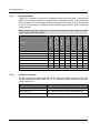
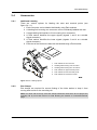
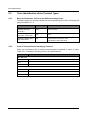
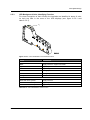
1
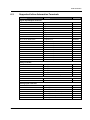
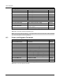
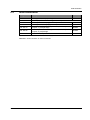
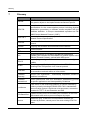
Inline with ICS Manual Revision 8 Liability / Imprint This manual is intended to provide support for installation and usage of the device. The information is believed to be accurate and reliable. However, SysMik GmbH Dresden assumes no responsibility for possible mistakes and deviations in the technical specifications. SysMik GmbH Dresden reserves the right to make modifications in the interest of technical progress to improve our modules and software or to correct mistakes. We are grateful for any feedback and suggestions. Further information (device description, available software) can be found on our homepage www.sysmik.de. Please ask for latest information from either our local authorized representatives or directly. SysMik disclaims all warranties in case of improper use or disassembly and software modifications not described in this document or when using improper or faulty tools. Commissioning and operation of the device by qualified personnel only. All applicable regulations have to be observed. © SysMik and the SysMik logo are registered trademarks of SysMik GmbH Dresden. ALTO™ © and IPOCS™ are trademarks of SysMik GmbH Dresden; "the new intelligence of control" , © © "beyond the limits!" und "networking together!" are subject to copyright of SysMik GmbH ® ® ® ® ® ® Dresden. Echelon , LON , LONW ORKS , LONMARK , LonBuilder , NodeBuilder , ® ® ® ® ® ® ® ® LonManager , LonTalk , LonUsers , LonPoint , Digital Home , Neuron , 3120 , 3150 , ® ® ® ® LNS , i.LON , LONW ORLD , Short Stack , the Echelon logo, and the LonUsers logo are trademarks of Echelon Corporation, registered in the USA and other countries. LonLink™, LonResponse™, LonSupport™, LONews™, LonMaker™, Panoramix™, Open Systems Alliance™, LNS Powered by Echelon™, Panoramix Powered by Echelon™ and LONW ORKS Powered by Echelon™ are trademarks of Echelon Corporation. LC7093™, LC3020™, L-IP™, L-Switch™ are trademarks of LOYTEC electronics GmbH. All other trademarks mentioned in this document are registered properties of their owners. These and further trademarks are used in this document but not marked for better readability. No part of this document may be reproduced or modified in any form without prior written agreement with SysMik GmbH Dresden. Copyright © 2012 by SysMik GmbH Dresden SysMik GmbH Dresden Bertolt-Brecht-Allee 24 01309 Dresden Germany 2 Tel Fax E-Mail (sales) E-Mail (support) Homepage + 49 (0) 351 - 4 33 58 - 0 + 49 (0) 351 - 4 33 58 - 29 [email protected] [email protected] http://www.sysmik.de Inline with ICS Contents Contents Inline with ICS 1 Preamble 6 2 Inline System Design 7 2.1 Overview 7 2.2 ICS Device Family 7 2.3 Automation Terminals 8 2.3.1 Digital Inputs 8 2.3.2 Digital Outputs 9 2.3.3 Relay Outputs 10 2.3.4 Analog Inputs 11 2.3.5 Analog Outputs 12 2.3.6 Function Terminals 12 2.3.7 Power and Segment Terminals 13 2.3.8 Accessory Terminals 14 2.4 Accessories 15 2.4.1 Additional Labeling 15 2.4.2 End Clamps 15 2.5 Color Identification of the Terminal Types 16 2.5.1 Base and Connector Colors for the different Voltage Areas 16 2.5.2 Color of Terminal Points Identifying Function 16 2.5.3 LED Background Color Identifying Function 17 2.6 Diagnosis and Status Displays 18 3 Assembly, Installation and Commissioning 19 3.1 Safety Advices 19 3.1.1 Intended Use 19 3.1.2 Use in Low Voltage Range 19 3.2 Mounting and Removing Inline Terminals 20 3.2.1 Mounting Requirements 20 3.2.2 Mounting Terminals 20 3.2.3 Removing and Exchanging Terminals 22 3 Contents 4 3.3 Grounding 23 3.3.1 Functional Earth Ground (FE) 23 3.3.2 Protective Earth 24 3.4 Shielding 24 3.4.1 Shielding Directions 24 3.4.2 Shielding of Analog Sensors and Actuators 24 3.5 Supply, Potential- and Data Jumpering 25 3.5.1 General 25 3.5.2 24 V DC Supply at the ICS from One Source 26 3.5.3 Additional Supply of Main and Segment Voltage with IB IL 24 PWR IN 27 3.5.4 Segmentation of UM and US for Actuator and Sensor Supply 28 3.5.5 Design of an AC area (e.g. 230 V) 29 3.5.6 Switching of 230 V AC with Relays 30 Additional Supply of Logic and Analog Voltage 31 3.6 Sequence of the I/O Terminals 31 3.7 Placement of Analog Terminals 31 3.8 Connecting Sensors and Actuators 32 3.8.1 Connection Technology 32 3.8.2 Connecting Digital In- and Output Terminals 32 3.8.3 1-Wire Connection of Digital Terminals 33 3.8.4 2-Wire Connection of Digital Terminals 33 3.8.5 3-Wire Connection of Digital Terminals 34 3.8.6 4-Wire Connection of Digital Terminals 34 3.8.7 Connecting Analog Terminals 35 4 Project Creation with Inline 36 4.1 General 36 4.2 Definition of the Project 37 4.2.1 Data Points 37 4.2.2 System Structure 38 4.3 Configuration of the Station 38 4.4 Installation 39 4.5 Commissioning 39 Inline with ICS Contents Inline with ICS 4.6 Wiring Test 39 4.7 Software Project Planning 40 4.8 Maintenance 40 4.8.1 Trouble Shooting 40 4.8.2 Modification and Extension 40 5 Technical Data 41 6 Order Information 42 6.1 ICS and Accessories 42 6.2 Supported Inline Automation Terminals 43 6.3 Power and Segment Terminals 44 6.4 Inline Accessories 45 7 Glossary 46 8 Literature 48 5 Preamble 1 Preamble This manual supports you in conception, design and commissioning of an Inline station with the InlineControlServer (ICS) as supplement to the ICS manual [1] and the Inline user manual [3]. Specific information about the individual ICS variants and Inline terminals can be found in the appropriate manuals and data specifications. 6 Inline with ICS Inline System Design 2 Inline System Design 2.1 Overview Inline is a modular I/O system by Phoenix Contact allowing for flexible, fast and space saving configuration of automation stations. An Inline station consists of a bus controller and a variety of automation terminals by quantity, type and sequence. In this document they are also shortly referred to as terminals: Input and output terminals for digital and analog signals Function terminals such as for gateways to other bus systems Supply and segment terminals for supply and setup of different voltage levels and fuse protection Accessory terminals such as for potential distribution The bus controller controls the Inline station and includes interfaces to the superordinate system. Up to 63 active automation terminals can be connected to a bus controller. Active terminals are all the I/O and function terminals able to communicate with the bus controller. Power and segment terminals are mainly passive. An Inline station is assembled without any tools. Potential and data jumpering within a station is achieved without additional wiring. The external terminal points are connected via a pluggable wiring level allowing for pre-wiring and easy terminal exchange. Inline terminals are designed for DIN rail mounting in closed sub-distributions. The width of automation terminals is indicated in multiples of a modular width (MW), a modular width is equal to 12.2 mm. 2.2 ICS Device Family The InlineControlServer is a bus controller family including the following core functions: Graphical programming EIA-709 protocol stack for communication in LONWORKS networks Configurable via console Additional functions are dependant upon the variant chosen: EIA-852 protocol stack for LONW ORKS over IP (LONMARK channel IP-852) Router between TP/FT-10 and IP-852 RNI (Remote Network Interface) for remote access to a LONW ORKS network for project planning, maintenance and visualization LPA backend (network interface for the LPA protocol analyzer by Loytec for network traffic diagnosis) BACnet/IP interface Fidelio interface (interface to the hotel front office solution by MICROSFIDELIO) A list of the available ICSs and accessories is included in section 6.1. For further information concerning functions, use and selection of the ICSs please check the ICS manual [1]. Inline with ICS 7 Inline System Design 2.3 Automation Terminals This chapter gives an overview of the most important Inline automation terminals for the ICS. There are further terminals supported by the ICS beside the terminals described here. Please contact SysMik ([7]) if you need a specific terminal type that is not listed here. For more detailed technical information about the terminals please refer to the technical documentations and data sheets from Phoenix Contact. The current version [2] is available for download or can be sent to you upon request. While installing the IPOCS programming tool, the data sheets for the IO Configurator are installed as well. During configuration of a station you can access the data sheets of the terminals used in the IO Configurator. These data sheets are subject to modification by Phoenix Contact. 2.3.1 Digital Inputs Device Channels Device width in 12.2 mm units Input voltage / V Connection technology / wires Table 2.3.1.1 represents a selection of available digital input terminals. Further to the number of channels and the module width the input voltage, 24 V DC or 230 V AC, is the most important selection criterion. The column "Connection technology / wires" shows what additional wiring points (GND, +24 V, FE) the terminal offers for each sensor channel. Further information is available in section 3.8. IB IL 230 DI 1-PAC 1 1 230 3 IB IL 24 DI 2-PAC 2 1 24 4 IB IL 24 DI 4-PAC 4 1 24 3 IB IL 24 DI 4-ME 4 1 24 3 IB IL 24 DI 8/HD-PAC 8 1 24 1 IB IL 24 DI 8-PAC 8 4 24 4 IB IL 24 DI 16-PAC 16 4 24 3 IB IL 24 DI 16-ME 16 4 24 3 IB IL 24 DI 32/HD-PAC Further terminals upon request 32 4 24 1) 1) 1) 1 3-wires connection only for 2 channels, 1-wire connection for the remaining 2 channels per 12.2 mm unit Table 2.3.1.1: Comparison of digital input terminals 8 Inline with ICS Inline System Design 2.3.2 Digital Outputs Connection technology / wires 1 Load current / A 1 12-253 V AC Device width in 12.2 mm units IB IL DO 1 AC-PAC 24 V DC Device Channels Table 2.3.2.1 represents a selection of supported digital output terminals. Selection criteria are the number of channels, module width, output voltage, maximum load current and connection technology (see also 2.3.1). Digital outputs for 24 V DC and TRIAC outputs for 12 – 253 V DC are available. 0.5 3 IB IL 24 DO 2-PAC 2 1 0.5 4 IB IL 24 DO 2 2A-PAC 2 1 2 4 IB IL 24 DO 4-PAC 4 1 0.5 3 IB IL 24 DO 4-ME 4 1 0.5 IB IL DO 4 AC-1A-PAC 4 4 IB IL 24 DO 8/HD-PAC 8 1 IB IL 24 DO 8-PAC 8 4 IB IL 24 DO 8-2A-PAC IB IL 24 DO 16-PAC IB IL 24 DO 16-ME 8 16 16 IB IL 24 DO 32/HD-PAC 32 1) 3 1 3 0.5 4 4 4 4 2 0.5 0.5 4 3 1) 3 4 0.5 1 Further terminals upon request 1) 3-wires connection only for 2 channels, 1-wire connection for the remaining 2 channels per 12.2 mm unit Table 2.3.2.1: Comparison of digital output terminals Inline with ICS 9 Inline System Design 2.3.3 Relay Outputs 1) 1 1 1 4 4 4 230 230 48 230 230 230 3 3 2 3 3 1) 16 High inrush current Rated current/ A 1 1 2 4 4 4 Gold plated contacts Max. switching voltage / V AC IB IL 24/230 DOR 1/W-PAC IB IL 24/230 DOR 1/W-PC-PAC IB IL 24/48 DOR 2/W-PAC IB IL 24/230 DOR 4/W-PAC IB IL 24/230 DOR 4/W-PC-PAC IB IL 24/230 DOR 4/HC-PAC Further terminals upon request Device width in 12.2 mm units Device Channels Table 2.3.3.1 provides an overview of the available relay terminals. Features are the number of channels, module width, output voltage, maximum switching voltage and nominal current. The high inrush capability is a special feature for use with capacitive loads as is found in luminaires. Several outputs up to 16 A while observing derating conditions! Table 2.3.3.1: Comparison of relay terminals 10 Inline with ICS Inline System Design 2.3.4 Analog Inputs Table 2.3.4.1 shows an overview of available analog input terminals. The terminals vary according to the number of channels, module width, dimensions and connection technology of the sensors. Measurement categories are current in the range 0 – 20 mA, voltage in the range of 0 – 10 V and resistance or temperature for Pt1000. In addition, some terminal types can be used for different measuring ranges. IB IL AI/TEMP 4 RTD-PAC 4 1 Connection technology / wires 1 Resistance / temperature 2 Current Device width in 12.2 mm units IB IL TEMP 2/RTD-PAC Voltage Device Channels Note: Detailed information referring to connection procedure and measuring range is available in the terminal related data sheets. 4 2 IB IL TEMP 4/8 RTD-PAC 8 4 IB IL AI 2/SF-PAC 2 1 2-3 3 IB IL AI 2/SF-ME 2 1 2 IB IL AI 4/EF-PAC 4 4 2-4 IB IL AI 8/SF-PAC 8 4 2 Further terminals upon request Table 2.3.4.1: Comparison of analog input terminals Inline with ICS 11 Inline System Design 2.3.5 Analog Outputs Table 2.3.5.1 shows an overview of available analog output terminals. The terminals differ in the number of channels, module width, output dimensions, load resistance, and resolution. The usual output ranges are voltage in the range 0-10 V and current in the 0 - 20 mA range. In addition, some terminal types can be used for different output ranges. IB IL AO 2/U/BP-PAC 2 1 IB IL AO 2/U/BP-ME IB IL AO 4/U/SF-PAC IB IL AO 4/8/U/BP-PAC 2 4 8 1 1 4 Connection technology /wires 1 4 Resolution / Bit 2 1 2 Load resistor / kΩ 1 IB IL AO 1/U/SF-PAC IB IL AO 2/SF-PAC Current Device width in 12.2 mm units IB IL AO 1/SF-PAC Voltage Device Channels Note: Detailed information referring to connection technology and output range is available in the terminal related data sheets. >2 16 2 >2 >2 16 16 2 2 >2 12 2 >2 >1 >2 12 10 15 2 2 2 Further terminals upon request Table 2.3.5.1: Comparison of analog output terminals 2.3.6 Function Terminals Function terminals supported by the ICS are DALI terminals for lighting control and the S0 terminals shown in table 2.3.6.1. For selection please observe the terminal related data sheet. Device Function IB IL DALI/PWR-PAC DALI master with DALI supply IB IL DALI-PAC DALI master, extension for IB IL DALI/PWR-PAC IB IL DI 8/S0-PAC S0 pulse counter, digital inputs Table 2.3.6.1: Function Terminals 12 Inline with ICS Inline System Design 2.3.7 Power and Segment Terminals Diagnosis Segment circuit fuse Supply Type Device Main circuit fuse The supply of power to an Inline-Station is initially achieved via the bus controller. If the requirements of the I/O terminals in an application exceed the capacities of the bus controller, e.g. concerning power requirement or galvanic isolation, additional supply and segment terminals will be required. Supply and segment terminals are required for: Assembly of galvanically isolated areas (e.g. 24 V and 230 V) Assembly of separated segments in the 24 V DC range (such as for separated fuse protection) Additional supply of electric circuits if the current capacity of the potential jumpering has been reached or the maximum power load of the source is exceeded. Table 2.3.7.1 is a selection support for power and segment terminals. IB IL 24 PWR IN/F-PAC IB IL 24 PWR IN/2-F-PAC IB IL 24 PWR IN/2-F-D-PAC IB IL 24 PWR IN/2F-DF-PAC IB IL 24 PWR IN/R-PAC Power terminal IB IL 24 PWR IN-PAC IB IL 24 SEG-PAC IB IL 24 SEG/F-PAC IB IL 24 SEG/F-D-PAC UM / US 3) 4) UL , UANA UM US 3) UL 4) UANA 5) L 2) , UM 5) 2) US IB IL 24 SEG-ELF-PAC 1) 2) 1) 2) , US L Segment terminal IB IL 230 PWR IN-PAC 1) Main voltage, see 3.5.1 Segment voltage, see 3.5.1 Logic voltage, see 3.5.1 Analog voltage, see 3.5.1 Line in voltage area 120 V AC / 230 V AC Table 2.3.7.1: Comparison of power and segment terminals Inline with ICS 13 Inline System Design 2.3.8 Accessory Terminals Part of the accessory terminals are Potential distribution terminals to provide additional terminal points for supply and ground Distance terminals for galvanic isolation of different voltage ranges from each other (e.g. 24 V DC and 230 V AC) Table 2.3.8.1 shows an overview of the available accessory terminals. Device Type IB IL PD 24V-PAC Terminal for 24 V potential distribution IB IL PD GND-PAC Terminal for GND potential distribution IB IL DOR LV-SET-PAC Spacer terminal block to separate voltage areas Table 2.3.8.1: Overview of the accessory terminals 14 Inline with ICS Inline System Design 2.4 Accessories 2.4.1 Additional Labeling There are various options for labeling the slots and terminal points (see figure 2.4.1.1): 1. Each connector can be labeled individually using Zack markers. 2. A labeling field covering one connector can be individually labeled with text. 3. A large labeling field similar to 2 but covering four connectors. 4. A Zack marker identifies the upper signals (signals 1 and 2 on a double signal connector). 5. A Zack marker identifies the lower signals (signals 3 and 4 on a double signal connector). 6. Each slot of the electronics base can be labeled using a Zack marker. 1 Zack marker for the connector 2 Labeling field covering one connector 3 Labeling field covering four connectors 4 Zack marker for upper terminal points 5 Zack marker for lower terminal points 6 Zack marker for electronics socket Figure 2.4.1.1: Labeling options 2.4.2 End Clamps End clamps are required for secure fixating of the Inline station to keep it from moving side to side on the mounting rail. Note: For Inline with ICS only such end clamps should be used which do not project the mounting rail by more than 30 mm to avoid blocking the release of connected Ethernet plugs. Inline with ICS 15 Inline System Design 2.5 Color Identification of the Terminal Types 2.5.1 Base and Connector Colors for the different Voltage Areas The basic range of a terminal voltage can be recognized by the color of housing and plug (see table 2.5.1.1). Area SELV (Safety Extra Low Voltage) terminals (24 V DC) Mains voltage (120 V AC / 230 V AC) Isolation between SELV and mains areas Housing color Connector color green green or black gray Gray gray green / gray divided green points to the SELV area gray points to the mains area Table 2.5.1.1: Housing and connector color 2.5.2 Color of Terminal Points Identifying Function There are connectors with or without terminal points identified in terms of color. Table 2.5.2.1 shows the meaning of the color identifications. Color Description 24 V DC area Red + Blue - Green Functional Earth FE 120 V AC / 230 V AC area Black Line L Blue Neutral N Green/Yellow Protective Earth PE Table 2.5.2.1: Terminal point color identification 16 Inline with ICS Inline System Design 2.5.3 LED Background Color Identifying Function For visual recognition of their function the terminals are identified in terms of color on their top side in the area of the LED displays (see figure 2.5.3.1 and table 2.5.3.1). Figure 2.5.3.1: Color identification of the terminal function Color Description 24 V DC area Black Supply terminal / segment terminal Light blue or blue Digital input Pink or red Digital output Green Analog input Yellow Analog output Orange Function terminal 120 V AC / 230 V AC area White with flash symbol Supply terminal Dark blue with flash symbol Digital input Claret-red with flash symbol Digital output Table 2.5.3.1: Color identification of the function Inline with ICS 17 Inline System Design 2.6 Diagnosis and Status Displays For failure diagnosis on site all terminals are provided with diagnosis and partially with status LEDs. The diagnosis LEDs indicate the operational status of the terminal. A terminal operates properly if all diagnosis LEDs are illuminated green. Status LEDs indicate the status of the appropriate input/output. Table 2.6.1 shows an overview of displays on different terminal types with uniform signification. The diagnosis and status displays provided by a terminal can be found in the terminal specific data sheet. LED UL UM US D (Diagnosis) State Description On UBK (24 V supply) and UL (7.5 V logic voltage) OK Off UBK, UL not OK On Voltage at main circuit (+24 V DC) Off No voltage at main circuit On Voltage at segment circuit (+24 V DC) Off No voltage at segment circuit Off No logic voltage On Logic voltage ok, data transmission on local bus is active 0.5 Hz Logic voltage ok, no data transmission on local bus 2 Hz 4 Hz Logic voltage ok, I/O error is present (see specific terminal documentation) Logic voltage ok, error at connection between previous and flashing terminal, e.g. loose contact, terminal before the flashing terminal failed, terminal hot-plugged (not permitted) Table 2.6.1: Diagnosis LEDs in Inline with general signification 18 Inline with ICS Assembly, Installation and Commissioning 3 Assembly, Installation and Commissioning 3.1 Safety Advices 3.1.1 Intended Use Inline terminals are exclusively intended for use within an Inline station according to the information in the terminal specific data sheets and this document. Note: Disconnect the entire station from the power supply prior to removing a terminal from the station or inserting a terminal in the station! Only reconnect after the entire stations has been set-up. 3.1.2 Use in Low Voltage Range Warning! Only qualified personnel (electricians or electro-technical skilled persons) are entitled to perform on Inline terminals within the range outside the safety extra-low voltage (SELV). During installation and commissioning please implicitly observe the notes in the terminal specific data sheets. Warning! Removing and inserting terminals for voltage ranges 120 V AC and 230 V AC is only to be carried out in the disconnected status! For all actions involving terminals and wiring always disconnect the supply voltage and secure against accidental reconnection.. Warning! The Inline terminals for the 120 V AC and 230 V AC voltage areas should only be operated in grounded AC voltage networks (AC networks). Note: Protect any low voltage range by an individual external fuse. Choose the value of the fuse in accordance with the line capacity, the maximum value of the fuse may not exceed 8 A. Please check the supply terminal data sheets for further restrictions! Inline with ICS 19 Assembly, Installation and Commissioning 3.2 Mounting and Removing Inline Terminals 3.2.1 Mounting Requirements Terminals of the Inline family with protection class IP 20 are designed for use in an enclosed switch cabinet or switch cabinets for snap assembly on DIN rails 35 mm x 7.5 mm according EN 60715 (supersedes EN 50022). Note: For optimum stability fix the DIN rail on a mounting plane or a back plane. The locking plate secures the end of an Inline station, protecting the station from electro static discharge pulses. The locking plate is part of the ICS scope of supply. Appropriate appliances such as end clamps have to be provided on both sides of the device in order to prevent the station from lateral movement on the mounting rail. Note: At the connection side of the ICS only, end brackets or terminals should be used which don’t project beyond the mounting rail by more than 30 mm to avoid blocking the release of connected Ethernet plugs. The end bracket CLIPFIX 35 fulfills this requirement (while CLIPFIX 35-5 does not). 3.2.2 Mounting Terminals An Inline station is assembled by plugging the individual components into each other. Lining-up establishes the potential and bus signal connection between the individual components of the station. To latch a terminal, proceed as per figure 3.2.2.1: 1. Disconnect the station from the power supply and insure no possible accidental reconnection is possible. Snap the electronic base on the mounting rail (A). Adjacent terminals are connected by keyway/featherkey connections (B). First insert the local bus contacts in the keyways of the previous terminal (B1). Insert the other potential jumpers into their keyways until they are securely locked (B2). Please make sure the contacts are properly connected (C2). C1 shows a common error where the featherkey is not in the keyway. 2. Once all the bases have been snapped on, plug the connectors into the appropriate bases. First place the front connector shaft in the front snap-on mechanism (D1), then pivot the top of the connector towards the base until it snaps into the back snap-on mechanism. 20 Inline with ICS Assembly, Installation and Commissioning 6452B010 Figure 3.2.2.1: Installation on the mounting rail (A), connection of Inline components to each other (B), connection check (C), plugging the wiring level (D) Inline with ICS 21 Assembly, Installation and Commissioning 3.2.3 Removing and Exchanging Terminals Individual terminals can be exchanged after set-up of the station. Figure 3.2.3.1 shows the removal of a terminal. Please observe the following procedure: 3. Disconnect the station from the power supply and secure it against reconnection. 1. If there is a labeling field, which covers several connectors, it may be necessary to remove it (A1). 2. Lift the connector of the terminal to be removed by pressing on the back connector shaft latching (A2) and remove the connector (B). 3. Remove the adjacent connectors of the neighboring terminals (C). 4. Press the snap-on mechanism (D1) and remove the electronics base from the mounting rail by pulling the base straight back (D2). Figure 3.2.3.1: Removing a terminal If you want to exchange a terminal, remove the appropriate terminal and insert the base of the new terminal at its position. Please ensure that all featherkeys and keyways on adjacent terminals are interlocked. 22 Inline with ICS Assembly, Installation and Commissioning 3.3 Grounding 3.3.1 Functional Earth Ground (FE) Functional earth grounding improves immunity to interference and is used for Inline within the 24 V DC area (SELV). Functional earth ground is led from the grounded bus coupler or power terminal through the 24 V DC area of the station using the FE potential jumper. For a reliable functional earth grounding please make sure that: The mounting rail is connected to the functional earth via grounding terminals with a wire of minimum diameter of 1.5 mm² (16 AWG). The FE spring (metal clip) at the bottom side of bus controllers, power and segment terminals have electrical contact with the mounting rail. The mounting rail has to be clean and corrosion-free. The bus controller is additionally grounded via the earth leakage protection clamping spot with a 1.5 mm² conductor and grounding terminal (see figure 3.3.1.1). 120 V AC or 230 V AC voltage areas interrupt the FE potential jumper. Therefore, a 24 V DC power terminal which is located directly behind such an area, must also be grounded using the FE terminal point (see terminal specific data sheet). 6452A013 Figure 3.3.1.1: Diagram of the additional functional earth grounding of a bus controller Inline with ICS 23 Assembly, Installation and Commissioning 3.3.2 Protective Earth Protective earth is a low-impedance path to protect the user from electric shock in case of a failure and is used outside the SELV area in the Inline system. Warning! Each power terminal of the 120 V AC or 230 V AC area must be connected to the 2 mounting rail with low impedance (min. 1.5 mm / AWG 16), otherwise no protection is provided (see figure 3.3.2.1). Furthermore, the mounting rail itself must be properly grounded as well. The PE (protective earth ground) potential jumper is led from the power terminal of the 120 V AC or 230 V AC area through this entire area to the next power terminal. Figure 3.3.2.1: Diagram of the additional grounding of a bus controller and protective earth ground connection 3.4 Shielding 3.4.1 Shielding Directions Fasten the shielding so that as much of the braided shield as possible is held underneath the clamp of the shield connection.. Make sure there is good contact between the connector and base. For shielding of the TP/FT-10 cable please observe the recommendations in [6]. 3.4.2 Shielding of Analog Sensors and Actuators Always connect analog sensors and actuators using shielded, twisted-pair cables. For connection please observe the respective instructions in the terminal specific data sheets. 24 Inline with ICS Assembly, Installation and Commissioning 3.5 Supply, Potential- and Data Jumpering 3.5.1 General There are several electric circuits within an Inline station, automatically set-up by latching the terminals to each other. The voltage of the different electric circuits is supplied to the connected terminals via potential jumpers. The bus terminal supply UBK is connected to the ICS. The ICS, supplied by UBK, is generating the voltages for the logic circuit UL and the analog circuit UANA. The main circuit with the voltage UM begins either at the bus controller or a power terminal and is led through the subsequent terminals to the next power terminal. From UM the segment voltage US can be tapped via different segment terminals. Thus several segments independent from each other can be set-up in the main circuit. The main circuit provides the supply voltage for these segments. Table 3.5.1.1 shows an overview of the type and significance of these electric circuits and voltages in an Inline station. Circuit Description Bus coupler supply UBK Logic circuit UL Analog circuit UANA Segment circuit US 24 V DC; this circuit supplies the ICS which generates the bus logic voltage and the analog voltage for the I/O terminals 7.5 V DC; this circuit supplies the protocol chips of the terminals 24 V DC; auxiliary voltage for analog peripherals of the terminals 24 V DC; supply of the peripherals of most terminals (e.g. digital inputs) 24 V DC; at segment terminals, the segment voltage US is provided from the main circuit UM Main circuit UM Limits 19.2 V DC to 30 V DC 7.13 V DC to 7.87 V DC max. 2 A 20.4 V DC to 28.8 V DC max. 0.5 A 19.2 V DC to 30 V DC, max. 8 A 19.2 V DC to 30 V DC, max. 8 A Table 3.5.1.1: Inline electric circuits and voltages The following sections provide an overview of the different supply options of an Inline station, from the easiest supply option via the bus controller, the supply of galvanically isolated ranges through to the additional supply of analog, logic, main and segment voltage. Inline with ICS 25 Assembly, Installation and Commissioning There are three selection criteria: Requirements of the application concerning voltage (24 V or 230 V AC) and fuse protection. Current consumption of the connected sensors and actuators Current consumption of the connected automation terminals from the logic circuit and the analog circuit. Note: The IPOCS IO Configurator indicates the approx. current consumptions, so you can decide to insert additional power terminals. Please observe the information in the terminal specific data sheets. 3.5.2 24 V DC Supply at the ICS from One Source The easiest option is to supply the station from the ICS using a single 24 V DC source. (see figure 3.5.2.1). Conditions are: The total current consumption of all Inline automation terminals from the logic circuit is max. 2 A. The total current consumption of all Inline automation terminals from the analog circuit is max. 0.5 A. The current from potential jumpers (UM, US, GND) nowhere exceeds 8 A. Derating (current load depending on the ambient temperature) is observed for devices with Ethernet connection. Note: When calculating the power supply and fuse requirement please observe that the power supply unit has to provide the quadruple nominal current for safe activation of the fuse. The maximum value of the fuse may be 8 A. e.g.: ICS-709 local bus UART UL+ UANA UL- ICS InlineControlServer7,5V 24V US UM US UM internally connected UBK / UM Figure 3.5.2.1: 24 V DC supply at the bus controller 26 Inline with ICS Assembly, Installation and Commissioning 3.5.3 Additional Supply of Main and Segment Voltage with IB IL 24 PWR IN Additional supply of main and segment voltage (see figure 3.5.3.1) is required if either the allowed current of the potential jumpers UM, US or GND is exceeded or groups of actuators or sensors are to be supplied galvanically isolated from each other. Figure 3.5.3.1 shows that the circuits UM1 and US1.1 and functional earth end at the power terminal IB IL PWR IN-PAC and are galvanically isolated from the circuits UM2 and US2.1. Please observe the note from section 0 concerning dimensioning of power supply and fuse. e.g.: ICS-709 IB IL 24 PWR IN-PAC local bus UART UL+ UANA UL- ICS InlineControlServer7,5V 24V US1.1 US2.1 UM1 UM2 US UM internally connected UBK1 / UM1 UM2 Figure 3.5.3.1: Additional supply at IB IL 24 PWR Inline with ICS 27 Assembly, Installation and Commissioning 3.5.4 Segmentation of UM and US for Actuator and Sensor Supply Figure 3.5.4.1 shows the Inline system options for segmentation of UM and US for actuator and sensor supply. As described in 3.5.3, separate main circuit areas can be created by means of the IB IL PWR IN-PAC terminals. A main voltage range can be further segmented by means of the IB IL 24 SEG-PAC terminals in order to fuse or switch segments individually. IB IL 24 PWR IN-PAC e.g.: ICS-709 IB IL 24 SEG-PAC local bus UART UL+ UANA UL- ICS InlineControlServer7,5V 24V US1.1 US2.1 US2.2 UM1 UM2 UM2 US UM internally connected UBK1 / UM1 UM2 Figure 3.5.4.1: Potential jumpering for segmentation within an Inline station 28 Inline with ICS Assembly, Installation and Commissioning 3.5.5 Design of an AC area (e.g. 230 V) Figure 3.5.5.1 shows the design of an Inline station with an AC area such as for TRIAC terminals. AC areas have to be set-up galvanically isolated from the rest of an Inline station, this especially applies to supply voltage. The supply terminal IB IL 230 PWR IN-PAC is used for galvanic isolation and AC supply. If possible, the AC area should be placed at the end of the Inline station to avoid setting-up a subsequent 24 V area with individual supply. Warning! Please observe the safety note in 3.1.2. IB IL 230 PWR IN-PAC e.g.: ICS-709 IB IL 24 PWR IN-PAC local bus UART UL+ UANA UL- ICS InlineControlServer7,5V 24V US1.1 US2.1 UM1 L1 UM2 US UM N internally connected L1 N UBK1 / UM1 UBK2 / UM2 Figure 3.5.5.1: Potential jumpering within an Inline station when setting-up an AC range Inline with ICS 29 Assembly, Installation and Commissioning 3.5.6 Switching of 230 V AC with Relays No supply is required when switching 230 V AC with relays, but galvanic isolation from the remaining Inline station. The isolation is achieved by the distance terminal IB IL DOR LV-SET-PAC (see figure 3.5.6.1). e.g.: ICS-709 IB IL DOR LV-SET-PAC IB IL 24 PWR IN-PAC local bus UART UL+ UANA UL- ICS InlineControlServer7,5V 24V US1.1 US2.1 UM1 UM2 US UM internally connected e.g.: N • IB IL 24/230 DOR 4/HC-PAC UM2 UBK1 / UM1 Figure 3.5.6.1: Switching 230 V AC within an Inline station Warning! Please observe the safety note in section 3.1.2. X 30 Inline with ICS Assembly, Installation and Commissioning Additional Supply of Logic and Analog Voltage Exceeding the maximum cumulative current for logic or analog circuit by the connected automation terminals is not permitted and can be avoided by additional supply using the terminal IB IL 24 PWR IN/R-PAC (see figure 3.5.7.1). Supply terminal: IB IL 24 PWR IN/R-PAC e.g.: ICS-709 local bus UART ICS InlineControlServer7,5V UL+ UANA UL- 7,5V 24V 24V US1.1 US2.1 UM1 UM2 US UM internally connected UBK1 / UM1 UM2 Figure 3.5.7.1: Additional supply of analog, logic, main and segment voltage 3.6 Sequence of the I/O Terminals Always arrange the terminals in the order of their current drain within a main circuit. A main circuit always begins at a bus controller or a supply terminal and goes to the next supply terminal. If no supply terminal is used the entire station is a single main circuit. Note: Install the terminals with the highest current drain first. The advantage is that the high supply current does not flow through the entire main circuit and thus not through all terminals. This results in the following advised sequence: 1. Digital output terminals 2. Digital input terminals including S0 counter terminal 3. Analog terminals 4. Relay and DALI terminals at the end of the station as they interrupt UM This rule concludes that terminals should be grouped according to their type. 3.7 Placement of Analog Terminals As current through the potential jumpers UM and US generates heating which decreases the measuring accuracy, all analog terminals of a main circuit should always be placed conjointly at the end of a main circuit (see 3.6). Inline with ICS 31 Assembly, Installation and Commissioning If analog terminals cannot be placed at the end of a station (e.g. due to cable length), a new main circuit for the subsequent terminals should be set-up by inserting a power terminal. 3.8 Connecting Sensors and Actuators 3.8.1 Connection Technology The digital I/O terminals of the Inline product family generally allow for connection of sensors and actuators in 1, 2, 3 or 4 wire technology. Analog terminals allow for connection of sensors in 2, 3- or 4 wire technology. Due to connector variants the following wiring technologies can be achieved at a single connector: 8 sensors or actuators in 1 wire technology 2 sensors or actuators in 2, 3 or 4 wire technology 4 sensors or actuators in 2 or 3 wire technology 2 sensors or actuators in 2, 3 or 4 wire technology with shielding (for analog sensors or actuators) 3.8.2 Connecting Digital In- and Output Terminals The following section deals with the connection options using terminals of the 24 V DC area as an example. The specifications apply appropriately adapted for the 120 V AC and 230 V AC range. A connection example is provided in each terminal specific data sheet. Connection 1-Wire 2-Wires 3-Wires 4-Wires Sensor signal Sensor supply 1) external X Ground - - Earth / shield - - - 1) NPN type input terminals use sensor signal and ground as 2-wire connection. Table 3.8.2.1: Overview of digital input terminal connections Connection 1-Wire 2-Wire 3-Wire 4-Wire Actuator signal Actuator supply - - external - - - Ground Earth / shield Table 3.8.2.2: Overview of digital output terminal connections 32 Inline with ICS Assembly, Installation and Commissioning 3.8.3 1-Wire Connection of Digital Terminals Figure 3.8.3.1 shows the 1-conductor connection of digital actuators and sensors. Figure 3.8.3.1: 1-wire connection of digital sensors (A) and actuators (B) Note: Sensors and the segment circuit of the Inline station have to be provided by the same voltage supply. Grounding of the actuators and grounding of the segment voltage supplying the actuators must have the same potential. 3.8.4 2-Wire Connection of Digital Terminals Figure 3.8.4.1: 2-wire connection of digital sensors (A) and actuators (B) Inline with ICS 33 Assembly, Installation and Commissioning 3.8.5 3-Wire Connection of Digital Terminals Figure 3.8.5.1: 3-wire connection of digital sensors (A) and actuators (B) 3.8.6 4-Wire Connection of Digital Terminals Figure 3.8.6.1: 4-wire connection of digital sensors (A) and actuators (B) 34 Inline with ICS Assembly, Installation and Commissioning 3.8.7 Connecting Analog Terminals All analog output terminals provide 2-wire connection with the signals output and ground. Some analog output terminals offer additionally a clamping spot for shield connection. Analog input terminals provide 2-, 3- or 4-wire connection, depending on terminal type. The function of the terminal points depends on the sensor type, differentiated between passive or active and resistance, current or voltage sensors. The wiring of the analog terminals depends of the terminal type. Note: When wiring analog terminals please observe the terminal specific data sheets as the wiring of analog terminals differs from that of the digital terminals. Inline with ICS 35 Project Creation with Inline 4 Project Creation with Inline 4.1 General The versatility of Inline provides the user with a high degree of freedom creating the project. There is not only one solution option but several alternatives allowing for different options related to both, price and functionality. The answer to the question whether an ICS Inline station is basically suited for a project depends on few basic conditions: Mounting rail assembly in a switch cabinet Space requirements Degree of protection IP 20 24 V DC supply The creation of a project starts with the analysis of the task to determine data points, communication relations and the system concept. A next step is the installation of the Inline components whereby some basic conditions have to be observed such as the order of the in- and output terminals within the station. Testing the installation is an important step to commissioning the system. Maintenance includes trouble shooting, modification and extension of an Inline station. 36 Inline with ICS Project Creation with Inline 4.2 Definition of the Project 4.2.1 Data Points Determination of the data points is part of the task analysis. The result is a tabular overview of all data points existing within the project (see table 4.2.1.1). Property Description Meaning General Direction Sensor or actuator / input or output Signal type Analog, digital or bus protocol (e.g. DALI) Voltage area 24 V DC, 120 V AC or 230 V AC Building of separate voltage areas Digital Actuators Switching characteristics Operating cycles, switching frequency Current Max. current, rated current, inrush current Relay or semiconductor switch Choice of relay contact material; current carrying capacity Analog Actuators Voltage Voltage range Current Current range or max. load Digital Sensors Type Frequency Using an auxiliary voltage Switch input, counter pulses of 16 Hz (S0) or Choice of digital or more pulse counter inputs Voltage or dry contact Analog Sensors Type Voltage, current or resistance Input range Interpretation of results, type of control Special Functions and Bus Protocols (e.g. DALI, S0 pulse counter) Speed Sample rate See setup and properties of the respective system. Table 4.2.1.1: Data point properties Inline with ICS 37 Project Creation with Inline 4.2.2 System Structure Further to the individual properties of the data points, the distribution and the communication relations among each other have to be determined. The assignment of the data points to the individual Inline stations is the result of this analysis. The following basic conditions should be observed: Time-critical procedures (e.g. button switches light) should be realized, if possible, in one station. The length of actuator/sensor cables generally should be less than 30 m. Please observe the indications in the module specific data sheet. In many cases the switch cabinet limits the width of the Inline station. 4.3 Configuration of the Station The selection of the Inline terminals can be realized by means of the data point list made up in section 4.2.1., whereby the following basic rules apply: Homogenous signals should be reduced to as little multi-channel terminals as possible. The terminals are supplied by the different circuits (UL, UM / US, UANA) of an Inline station. The power requirement can be found in the specific data sheets. Please observe that the maximum admissive currents are not exceeded. If necessary, add supply terminals. The IO Configurator of the IPOCS development environment supports the power requirement calculation of the station and calculates the total length of the station to verify the space requirements in the switch cabinet. Within a station the terminals should be arranged in the order stated in section 3.6. If a station includes both voltage ranges, 24 V DC and 230 V AC, the 24 V DC range should begin directly at the bus controller and the 230 V AC range should be arranged, if possible, at the end of the station. If another 24 V DC range is located behind a 230 V AC range, a supply terminal has to be set for the latter. 38 Inline with ICS Project Creation with Inline 4.4 Installation Check the installation using the following checklist: Are all terminals located in their designated position? You can check the proper arrangement on the basis of the color identification of the function (see section 2.5.3) Are the terminals properly latched (see section Fehler! Verweisquelle konnte nicht gefunden werden.)? Gaps between the terminals signify faulty latching. Is the additional functional earth connection of the bus controller available and properly realized (see section 3.3.1)? Are 120 V AC / 230 V AC areas separated by distance terminals (see sections 3.5.5 and 0)? These areas are characterized by their gray housing color, the distance terminals by their gray/green plug. Has the end plate been mounted? Has the station been mechanically secured on both sides by end clamps? 4.5 Commissioning A number of tests to check the installation can even be conducted prior to programming and configuration of the bus controller. Please proceed as follows: 1. Establish the supply voltage. The bus controller now boots. This may take a few tens of seconds and is indicated by the service LED of the bus controller illuminated yellow (see [1]). You recognize that the boot procedure is completed once the service LED goes out and the RUN LED is illuminated red or green. 2. Check the LEDs of the bus controller (see [1]) and the Inline terminals (see section 2.6). Especially turn your attention to the diagnosis LED (D). If the local bus runs properly, it has to be continuously illuminated on all terminals. 4.6 Wiring Test During the wiring test cabling of the connected sensors and actuators is verified as well as the bus wiring (TP/FT-10, Ethernet) of the bus controller. Depending on the type, in- and output terminals are provided with status indicators to display the signal level. This applies in particular to terminals with digital in- and outputs. The wiring of the digital sensor connections can be checked by manipulation of the sensor signals. The display and keypad feature of the ICS bus controllers bearing the code ‚M’ allows for manual setting of the digital and analog outputs, independent from the application, provided that the application does not deactivate this function. The Ethernet wiring can be checked by the behavior of the Link and the Speed LED (see [1]). The wiring of the TP/FT-10 connection can be checked by a communication test (sending a service message via service button and receiving it using an appropriate Tool). Inline with ICS 39 Project Creation with Inline 4.7 Software Project Planning Software project planning and development are achieved with IPOCS. Please get the appropriate information from [4] and the documentation included in the installation. IPOCS is beyond pure Software development. For example the IPOCS IO Configurator supports you in terminal selection and configuration of the station. Further tools such as the PlugInCreator for the generation of LNS-Plugins and web visualization are part of the IPOCS tool suite. 4.8 Maintenance 4.8.1 Trouble Shooting For trouble shooting proceed as for installation (see 0) and commissioning (see Fehler! Verweisquelle konnte nicht gefunden werden.). For error diagnostics please use the diagnosis and status LEDs on the Inline terminals (see 2.6), the specific terminal documentation and in particular the ICS manual [1]. This manual includes a section with typical error descriptions and their possible cause. When exchanging terminals please observe the directions in section Fehler! Verweisquelle konnte nicht gefunden werden.. 4.8.2 Modification and Extension For modification and extension of the Inline station please make sure that the respective terminals are inserted, according to their type, at the proper position within the Inline station (see section 3.6) and their voltage range (see section 3.5.5). Usually terminal configuration and software have to be adapted if terminals are added. 40 Inline with ICS Technical Data 5 Technical Data For the technical data of the Inline system and the terminals please refer to [3] and the documentations of the respective terminals. Following please find selected technical data related to the Inline system. System data Number of devices in an Inline station max. 63 devices (automation terminals) Bus Controller Supply UBK Nominal voltage Ripple Permissible voltage range 24 V DC ±5% 19.2 V DC to 30.0 V DC, ripple included Logic Circuit UL Nominal voltage Ripple Load current 7.5 V DC ±5% max. 2 A (observe derating, see [1]) Analog circuit UANA Nominal voltage Ripple Permissible voltage range Load current 24 V DC ±5% 19.2 V DC to 30.0 V DC, ripple included max. 0.5 A Main and Segment Circuit UM and US Nominal voltage Ripple Permissible voltage range Load current 24 V DC ±5% 19.2 V DC to 30.0 V DC, ripple included max. 8 A Connectors Connection type Rated cross section Insulation stripping length spring-clamp 0.2 mm² to 1.5 mm², AWG 24-16 8 mm Environmental Conditions Note: This information represent standard values for the Inline system. For detailed information please refer to the manual of the particular device. Operating temperature Storage temperature Degree of protection (IEC 60529) -25 °C to 55 °C -25 °C to 85 °C IP20 Table 0.1: Technical data Inline with ICS 41 Order Information 6 Order Information 6.1 ICS and Accessories Variant Configuration Part no. ICS-709 TP/FT-10 1226-100202-01-7 ICS-709M TP/FT-10, display and keypad 1226-100202-02-4 ICS-709-I TP/FT-10, IP 1226-100202-18-5 ICS-709M-I TP/FT-10, IP, display and keypad 1226-100202-19-2 ICS-852 TP/FT-10, IP, IP-852, LPA 1226-100202-03-1 ICS-852M TP/FT-10, IP, IP-852, LPA, display and keypad 1226-100202-04-8 ICS-852X TP/FT-10, IP, IP-852, LPA, router 1226-100202-09-3 ICS-709-B TP/FT-10, IP, IP-852, router, LPA, display and keypad TP/FT-10, IP, BACnet ICS-709M-B TP/FT-10, IP, BACnet, display and keypad 1226-100202-08-6 ICS-852-B 1226-100202-14-7 ICS-709-F TP/FT-10, IP, IP-852, LPA, BACnet TP/FT-10, IP, IP-852, LPA, BACnet, display and keypad TP/FT-10, IP, IP-852, router, LPA, BACnet TP/FT-10, IP, IP-852, router, LPA, BACnet, display and keypad TP/FT-10, IP, Fidelio ICS-709-B-F TP/FT-10, IP, BACnet, Fidelio 1226-100202-33-8 ICS-852-F Accessories TP/FT-10, IP, IP-852, LPA, Fidelio 1226-100202-32-1 ICS-852MX ICS-852M-B ICS-852X-B ICS-852MX-B 1226-100202-05-5 1226-100202-07-9 1226-100202-15-4 1226-100202-16-1 1226-100202-17-8 1226-100202-06-2 ACC-ICS-RJ12-SUB-9F RS232-cable RJ12 to DSUB-9 female 1151-100231-01-2 ACC-ICS-RJ12-RS485 RS-485 adapter with cable 150 mm 1151-100366-01-1 IPOCS-USB IPOCS-4.1 full version; USB dongle 1503-100081-13-3 IPOCS-C IPOCS-4.1 full version; parallel port dongle upon request Table 6.1.1: Order information for ICS and accessories 42 Inline with ICS Order Information 6.2 Supported Inline Automation Terminals Device 1) Function Part no.1) 1 input 230 V 2 inputs 24 V 4 inputs 24 V 4 inputs 24 V 8 inputs 24 V, 1 DU 8 inputs 24 V 16 inputs 24 V 16 inputs 24 V 32 inputs 24 V 2 transistor outputs 24 V DC / 0.5 A 2 transistor outputs 24 V DC / 2 A 4 transistor outputs 24 V DC / 0.5 A 4 transistor outputs 24 V DC/ 0.5 A 8 transistor outputs 24 V DC/ 0.5 A, 1 DU 8 transistor outputs 24 V DC/ 0.5 A 8 transistor outputs 24 V DC/ 2 A 16 transistor outputs 24 V DC/ 0.5 A 16 transistor outputs 24 V DC/ 0.5 A 32 transistor outputs 24 V DC/ 0.5 A 2861548 2861221 2861234 2863928 2700173 2861247 2861250 2897156 2862835 2861470 2861263 2861276 2863944 2700172 2861289 2861603 2861292 2897253 2862822 1 change over contact 230 V / 3 A 1 change over contact 230 V / 3 A 2 change over contacts 48 V / 2 A 4 change over contacts 230 V / 3 A 4 change over contacts 230 V / 3 A 4 bistable 230 V / 16 A, high inrush current 2861881 2862178 2863119 2861878 2862181 2897716 1 x TRIAC 12-253 V AC / 0.5 A 4 x TRIAC 12-253 V AC / 1 A 2861920 2861658 2 x voltage, current 2 x voltage, current 2 x resistance, temperature 4 x voltage, resistance, temperature 4 x voltage, current 8 x resistance, temperature 8 x voltage, current 2861302 2863944 2861328 2897952 2878447 2863915 2861412 Digital Input/Output Terminals IB IL 230 DI 1-PAC IB IL 24 DI 2-PAC IB IL 24 DI 4-PAC IB IL 24 DI 4-ME IB IL 24 DI 8/HD-PAC IB IL 24 DI 8-PAC IB IL 24 DI 16-PAC IB IL 24 DI 16-ME IB IL 24 DI 32/HD-PAC IB IL 24 DO 2-PAC IB IL 24 DO 2 2A-PAC IB IL 24 DO 4-PAC IB IL 24 DO 4-ME IB IL 24 DO 8/HD-PAC IB IL 24 DO 8-PAC IB IL 24 DO 8 2A-PAC IB IL 24 DO 16-PAC IB IL 24 DO 16-ME IB IL 24 DO 32/HD-PAC Relay Terminals IB IL 24/230 DOR 1/W-PAC IB IL 24/230 DOR 1/W-PC-PAC IB IL 24/48 DOR 2/W-PAC IB IL 24/230 DOR 4/W-PAC IB IL 24/230 DOR 4/W-PC-PAC IB IL 24/230 DOR 4/HC-PAC TRIAC Terminals IB IL DO 1 AC-PAC IB IL DO 4 AC-1A-PAC Analog Input Terminals IB IL AI 2/SF-PAC IB IL AI 2/SF-ME IB IL TEMP 2 RTD-PAC IB IL AI/TEMP 4 RTD-PAC IB IL AI 4/EF-PAC IB IL TEMP 4/8 RTD-PAC IB IL AI 8/SF-PAC Inline with ICS 43 Order Information Analog Output Terminals IB IL AO 1/SF-PAC IB IL AO 1/U/SF-PAC IB IL AO 2/SF-PAC IB IL AO 2/U/SF-PAC IB IL AO 2/U/BP-ME IB IL AO 4/U/SF-PAC IB IL AO 4/8/U/BP-PAC 1 x voltage, current 1 x voltage 2 x voltage, current 2 x voltage 2 x voltage 4 x voltage 8 x voltage 2861315 2861399 2863083 2861467 2863957 2692050 2878036 Function and Communication Terminals IB IL DALI/PWR-PAC DALI master with DALI supply 2897813 IB IL DALI-PAC DALI master, extension terminal 2897910 IB IL DALI/MM-PAC DALI master with DALI supply, multi master support 2700605 IB IL DI/S0-PAC 8 S0 counter inputs / digital inputs 2897020 1) Device names and part numbers of Phoenix Contact apply. Table 6.2.1: Automation terminals supported by ICS Note: All terminals listed in table 6.2.1 are approved for the use in the ICS. If other terminals are to be used please contact SysMik [7]! 6.3 Power and Segment Terminals 1) 1) Device Function Part no. IB IL 24 PWR IN-PAC IB IL 24 PWR IN/F-PAC IB IL 24 PWR IN/2-F-PAC IB IL 24 PWR IN/2-F-D-PAC IB IL 24 PWR IN/2F-DF-PAC IB IL 24 PWR IN/R-PAC IB IL 24 SEG-PAC IB IL 24 SEG/F-PAC IB IL 24 SEG/F-D-PAC IB IL 24 SEG-ELF-PAC IB IL PD 24V-PAC IB IL PD GND-PAC IB IL 230 PWR IN-PAC IB IL DOR LV-SET-PAC 24 V feed in 24 V fused feed in 24 V fused feed in 24 V fused feed in with diagnostics 24 V fused feed in with diagnostics Supply of bus electronics (UL, UANA) 24 V segment supply 24 V fused segment supply 24 V fused segment supply with diagnostics 24 V fused segment supply Distribution of 24 V segment voltage Distribution of GND 230 V feed in Spacer terminal to separate 230 V and 24 V 2861331 2861438 2862136 2862152 2863779 2861674 2861344 2861373 2861904 2861409 2862987 2862990 2861535 2861645 1) ) Device names and part numbers of Phoenix Contact apply. Table 6.3.1: Power and segment terminals 44 Inline with ICS Order Information 6.4 Inline Accessories Designation 1) IL CP ZB 6 IB IL FIELD 2 IB IL FIELD 8 ESL 62X10 ESL 62X46 CLIPFIX 35 1) ) 1) Description Part no. Coding profile, 100 pcs/package Zack strip (see Phoenix catalog „CLIPLINE“) Labeling field for one plug (12.2 mm) Labeling field for four plugs (48.8 mm) Insert strip for IB IL FIELD 2, perforated, for laser printers, 72-parts, 1 piece/package Insert strip for IB IL FIELD 8, perforated, for laser printers, 15-parts, 5 pcs/package End bracket, snap-on without tools 2742683 2727501 2727515 0809502 0809502 3022218 Device names and part numbers of Phoenix Contact apply. Table 6.4.1: Order information for Inline accessories Inline with ICS 45 Glossary 7 Glossary Term Explanation BACnet ISO EN16484.5 communication protocol for building automation with generic objects to be implemented manufacturer specific. CEA-709 International standard based on extended LONW ORKS specifications for the communication protocol including physical transmission procedures on different media compliant with the LONMARK definition. In Europe standardized equivalent as EN14908 Control Network Protocol („CNP“). CEA-709.1 Standard of the communcation protocol known als LON "Control Network Protocol Specification" CEA-852 Use of the IP channel as transmission medium for the LONW ORKS protocol Echelon Company that invented and marketed control networks FE Functional Earth GND Ground, 0 V InlineControlServer for LONMARK and BACnet applications (SysMik). Bus controller for the scalable I/O terminal system Inline Modular (Phoenix Contact), optional with WEB server. Graphic programming tool for controllers and I/O modules (by SysMik) ICS IPOCS 46 IP-852 Channel type specified by LONMARK based on CEA-852 for tunneling of the 709 protocol via IP internet protocol Local bus Channel for the communication of the Inline bus controller with the automation terminals within an Inline station LONMARK Germany German user organization – membership corporation; affiliate of LONMARK International LONMARK International Global manufacturer and user association standardizing profiles for specific applications and Interoperability Guidelines LONW ORKS Trade name for the technology platform for control networks by Echelon primarily including the ANSI-/CEA-709.1 standardized communication protocol, the Neuron microprocessor, transceiver modules for TP/FT-10 and Powerline and LNS LPA-Back-End Software module on the ICS enabling the evaluation of the CEA709 network traffic with an protocol analyzer by Loytec Neuron LONW ORKS chip, LONW ORKS communication controller etc. provided by Echelon; central part of the most existing CEA-709 nodes Inline with ICS Glossary Inline with ICS RNI „Remote Network Interface“. External network interface directly at the CEA-709 network; communication with the control station via IP using a specific protocol. TP/FT-10 Channel type specified by LONMARK; standard Twisted Pair technology with free topology, most common channel type, 78 kBit/s UANA Supply of the analog circuit UBK Supply of the bus controller UL Supply of the logic circuit UM Supply of the main circuit US Supply of the segment circuit 47 Literature 8 48 Literature [1] ICS Manual, SysMik GmbH Dresden, 2007 [2] www.phoenixcontact.com [3] User manual IL SYS INST UM E: "Automation Terminals of the Inline Product Range", Phoenix Contact, Phoenix order no. 2698737 [4] IPOCS, First Steps in IPOCS 4.1, SysMik GmbH Dresden (part of IPOCS 4.1.x installation) [5] LONW ORKS FTT-10A Free Topology Transceiver User’s Guide, Echelon Corporation [6] LONW ORKS Wiring Guidelines, SysMik GmbH Dresden [7] www.sysmik.com Inline with ICS