1
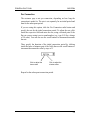
GlobalView User’s Guide
Version 1.40
TABLE OF CONTENTS
1. Introduction .............................................................................................................. 1-1
1.1 Overview.............................................................................................................. 1-1
1.2 G.Loop Description.............................................................................................. 1-1
1.3 System Interfaces ................................................................................................. 1-1
1.4 Main Features....................................................................................................... 1-2
1.5 Minimum System Requirements .......................................................................... 1-3
1.6 Scope of User's Guide .......................................................................................... 1-4
2. Installation ................................................................................................................ 2-1
2.1 General................................................................................................................. 2-1
2.2 GlobalView Software Installation ........................................................................ 2-1
2.3 Connecting to the G.Loop Unit ............................................................................ 2-4
2.4 Starting the GlobalView Application ................................................................... 2-5
2.5 Daylight Savings Time Setting............................................................................. 2-5
3. Getting Started with GlobalView......................................................................................... 3-1
3.1 Operating Conventions......................................................................................... 3-1
3.1.1 Window Controls.......................................................................................... 3-1
3.1.2 Command Buttons ........................................................................................ 3-3
3.1.3 Context-Sensitive Menus.............................................................................. 3-3
3.1.4 Changing the GUI Look & Feel ................................................................... 3-3
3.2 The GlobalView Main Window........................................................................... 3-4
3.2.1 The Tree View.............................................................................................. 3-5
3.2.2 Graphical Depiction of the Hierarchy........................................................... 3-6
3.2.3 The Selected Object ..................................................................................... 3-6
3.2.4 Restoring the Tree View............................................................................... 3-6
3.2.5 The Log Window.......................................................................................... 3-6
3.3 Saving the Existing Configuration ....................................................................... 3-7
3.4 Loading an Existing Configuration ...................................................................... 3-7
3.4.1 The Autoload Option.................................................................................... 3-8
3.5 Setting the Operation Mode ................................................................................. 3-8
3.6 Exiting GlobalView ........................................................................................... 3-10
i
GlobalView User's Guide
Table of Contents
4. Management Operations ......................................................................................... 4-1
4.1 Adding a New Site ............................................................................................... 4-1
4.1.1 Renaming a Site............................................................................................ 4-2
4.2 Adding a New G.Loop Unit ................................................................................. 4-2
4.2.1 The G.Loop View......................................................................................... 4-3
4.2.2 Color Coding in the G.Loop View ............................................................... 4-5
4.2.3 Enabling/Disabling Ports.............................................................................. 4-5
4.2.4 Viewing Port Information............................................................................. 4-6
4.3 Deleting Objects................................................................................................... 4-8
4.4 Preparing Reports................................................................................................. 4-9
4.4.1 Selecting the Report Type .......................................................................... 4-10
4.4.2 Specifying the Time Frame......................................................................... 4-10
4.4.3 Specifying the Report Scope ...................................................................... 4-11
4.4.4 Specifying the Report Filters ...................................................................... 4-11
4.4.5 Specifying the Report Output Options........................................................ 4-12
4.4.6 Generating the Report................................................................................. 4-13
4.5 Adding New Rooms ........................................................................................... 4-14
4.6 Adding Internet Kiosks ...................................................................................... 4-15
4.6.1 Assigning the Room to a Port..................................................................... 4-16
4.6.2 Viewing Room Data ................................................................................... 4-17
4.6.3 Editing Room Data ..................................................................................... 4-18
4.7 SNMP Data ........................................................................................................ 4-18
4.7.1 Community Name Settings ......................................................................... 4-18
4.7.2 Polling Intervals ......................................................................................... 4-19
5. Hotel Mode................................................................................................................ 5-1
5.1 Configuring the PMS Interface ............................................................................ 5-1
5.1.1 Serial Port Settings ....................................................................................... 5-3
5.1.2 Configuring GlobalView in Standalone Mode ............................................. 5-4
5.1.3 Printer Settings ............................................................................................. 5-5
5.2 Accounting Policy................................................................................................ 5-6
5.2.1 Setting the Accounting Options for Rooms .................................................. 5-8
5.2.2 Internet Kiosk Accounting Policy............................................................... 5-11
5.3 The Add Rooms Option ..................................................................................... 5-12
5.4 Assigning a Room to a Port................................................................................ 5-13
5.5 Using Automatic Room Assignment .................................................................. 5-14
5.6 Unassigning a Room .......................................................................................... 5-15
5.7 The Hotel View.................................................................................................. 5-15
5.7.1 General ....................................................................................................... 5-15
5.7.2 Hotel View Modes...................................................................................... 5-16
5.7.3 Starting the Hotel View .............................................................................. 5-16
5.7.4 Hotel View Operations ............................................................................... 5-18
5.7.5 Accepting Prepayment for a Room............................................................. 5-19
5.7.6 Viewing the Time Remaining..................................................................... 5-20
5.7.7 Charging for Internet Kiosk Access............................................................ 5-20
ii
GlobalView User's Guide
Table of Contents
TABLE OF FIGURES
Figure 2-1. Install Anywhere...................................................................................... 2-2
Figure 2-2. Preparing to Install Window.................................................................... 2-2
Figure 2-3. Introductory Window .............................................................................. 2-3
Figure 2-4. License Agreement ................................................................................. 2-3
Figure 2-5. Installation Destination........................................................................... 2-4
Figure 3-1. The GlobalView Main Window ............................................................. 3-4
Figure 3-2. Load Tree Window................................................................................. 3-7
Figure 3-3. Hotel View ............................................................................................. 3-9
Figure 4-1. Add New Site ......................................................................................... 4-1
Figure 4-2. Add New G.Loop Unit ........................................................................... 4-2
Figure 4-3. The G.Loop View................................................................................... 4-3
Figure 4-4. Port Information Window....................................................................... 4-6
Figure 4-5. Report Window ...................................................................................... 4-9
Figure 4-6. Date Selection Box............................................................................... 4-10
Figure 4-7. Example Report.................................................................................... 4-13
Figure 4-8. New Room Window ............................................................................. 4-14
Figure 4-9. Assign Room to Port ............................................................................. 4-16
Figure 4-10. Assign Room Dialog Box................................................................... 4-17
Figure 4-11. Community Name............................................................................... 4-19
Figure 4-12. Polling Parameters.............................................................................. 4-19
Figure 5-1. Interface Setup........................................................................................ 5-2
Figure 5-2. Serial Port Setup..................................................................................... 5-3
Figure 5-3. Print Setup .............................................................................................. 5-5
Figure 5-4. Accounting Policy Window.................................................................... 5-7
Figure 5-5. Internet Kiosk Accounting Policy Window .......................................... 5-11
Figure 5-6. Create New Room Dialog Box ............................................................. 5-12
Figure 5-7. Assign Room to Port ............................................................................ 5-13
Figure 5-8. Automatic Rooms Assignment ............................................................. 5-14
Figure 5-9. Hotel View Window............................................................................. 5-17
Figure 5-10. Room Prepayment .............................................................................. 5-19
Figure 5-11. Kiosk Prepayment .............................................................................. 5-20
iii
1.
Introduction
1.1 Overview
GlobalView is an SNMP-based management system for G.Loop IP-based
Internet service units. It is intended to be used as a monitoring,
accounting, configuration and management tool for G.Loop units.
1.2 G.Loop Description
G.Loop is an innovative, integrated, IP-based platform that provides fast,
convenient and affordable Internet access to multiple independent users
within one contained facility. This includes office complexes, hotels,
residential buildings, college dormitories, and Internet kiosks.
G.Loop acts as an onsite PoP (Point of Presence) that offers high-speed
performance at low prices with excellent security to users throughout the
facility. Moreover, G.Loop patented technology makes it possible for
facilities to offer high-speed Internet access service to its tenants without
incurring great expenses, both before and after installation.
1.3 System Interfaces
GlobalView communicates with G.Loop units over TCP/IP using the
SNMP protocol.
Other interfaces include a printer, keyboard, mouse and PMS interface.
1-1
Introduction
GlobalView User's Guide
1.4 Main Features
The following are some of the GlobalView system features:
1-2
•
View port status and malfunctions in windows that simulate the actual
G.Loop front panel. On-screen color-coding ensures that operators are
informed of alarms quickly and efficiently.
•
Enable/disable individual ports on G.Loop units. View connection
status of individual ports.
•
Accounting package allows user-defined settings for billing hotel
guests and users.
•
View statistical and performance data on port and unit usage.
•
Hotel operation modes with a simplified GUI Hotel View that allows
hotel management staff to perform basic hotel-related operations (e.g.,
settling the customer’s bill) quickly and easily.
•
Optional Property System Management (PMS) interface (MicrosFidelio, Eltrax and Rotstein Informatix systems are currently
supported).
•
Report module allows generation of usage reports.
GlobalView User's Guide
Introduction
1.5 Minimum System Requirements
The following list the minimum requirements for the GlobalView PC.
Processor
Pentium II or Celleron 366 MHz
Operating System
Windows NT Workstation or
Windows 2000 Professional
Memory
At least 128 MB RAM
Disk Space
At least 100 MB free space
CD-ROM Drive
Optional*
Network Card
Standard NIC (Network
Interface Card)
Printer
Optional; any type compatible
with Windows can be used.
* The GlobalView installation program can be installed from a CD-ROM,
or can be downloaded from one of the following sites:
Web Site
www.globaloop.com/download/GlobalView
no user name or password is required.
FTP Site
ftp.globaloop.com (199.203.223.105)
user name: gview
password: glp.
1-3
Introduction
GlobalView User's Guide
1.6 Scope of User's Guide
This manual contains the following chapters.
Chapter 2.
Installation
Describes installation of the GlobalView software and connection of the
management station to G.Loop units.
Chapter 3.
Getting Started
Describes basic GlobalView operation.
Chapter 4.
Management Operations
Describes the basic management functions provided by GlobalView.
Chapter 5.
Hotel Mode
Describes GlobalView operation in Hotel mode.
1-4
2.
Installation
2.1 General
This chapter describes installation of the GlobalView application. All
software components (including the database software) necessary for
installation are supplied on a single CD-ROM.
2.2 GlobalView Software Installation
The GlobalView installation program can be installed from a CD-ROM,
or can be downloaded from one of the following sites:
Web Site
www.globaloop.com/download/GlobalView
no user name or password is required.
FTP Site
ftp.globaloop.com (199.203.223.105)
user name: gview
password: glp.
Click the Windows Start button and select Run.
Type path:glv<ver>.exe (path refers to the location where the file
is located and <ver> is the current version, e.g. D:glv1.40.exe) and click
OK.
2-1
GlobalView User's Guide
Installation
The Install Anywhere dialog box is displayed, followed by the Preparing
to Install window.
Figure 2-1. Install Anywhere
Figure 2-2. Preparing to Install Window
Select the language of use when the above screen is displayed; the default
language is English. The language selection determines the language in
which the Installation program prompts are displayed.
Click
2-2
to continue the installation.
Installation
GlobalView User's Guide
Figure 2-3. Introductory Window
Click
when the Introductory window (shown above) is displayed.
Figure 2-4. License Agreement
when the License Agreement window (shown above) is
Click
displayed, after having read and agreed to the terms of the license.
2-3
GlobalView User's Guide
Installation
Figure 2-5. Installation Destination
Specify the directory location to install the GlobalView management
application. If you choose not to accept the default location, click the
button and use standard Windows navigation to specify the
directory.
If you started to change the directory location and wish to revert to the
.
default location, click
Click
. Wait a few moments while the installation program copies
the program files to the specified location on the hard disk. In the
displayed Installing window, a progress bar at the bottom indicates the
time left until installation is completed.
After the installation program has completed, click
.
2.3 Connecting to the G.Loop Unit
The management connection to G.Loop units is made via a local or wide
area network. The GlobalView application sends SNMP requests and
receives SNMP replies from the G.Loop units it manages. Consult the
Network Manager for more information.
2-4
Installation
GlobalView User's Guide
2.4 Starting the GlobalView Application
By default, the installation program inserts the GlobalView application
into the StartUp folder, which means that the application is started
automatically after the user logs in to the PC station.
To manually start the GlobalView application:
Start the GlobalView application by double clicking the
placed on the Windows desktop.
Or
From the
icon
Ö
menu, choose Programs GlobalView.
Note: By default, only one session of GlobalView can be run on a PC
workstation. Should you try to start another session of
GlobalView, a message will be displayed informing that a
session is already running.
2.5 Daylight Savings Time Setting
By default, the GlobalView application adjusts its clock to reflect the
daylight savings time according to the setting of the Windows operating
system. Therefore, when Windows adjusts the system clock due to
changes in the daylight savings time, GlobalView automatically makes
the same adjustment.
The time of day is important for the report and accounting features of
the system, and therefore it is important that this adjustment be made
accurately. Since Windows does not always adjust the daylight savings
time accurately (in some countries), you can set the GlobalView
application to ignore the Windows automatic daylight savings time
adjustment. When you make this setting, GlobalView ignores the hour
added or subtracted from the system time of day.
To set GlobalView to ignore the daylight savings time adjustment:
2-5
GlobalView User's Guide
Installation
Use notepad (or another editor) to open the following text file:
/Program Files/GlobalView/glv.properties
Find the following line in the file (Hint - use the Find function).
GlobalView/use_timezone_daylight_savings.boolean=true
When the value of this parameter is set to true, the GlobalView clock
time is adjusted automatically by GlobalView, as follows.
Greenwich Mean Time (GMT) + local time zone + Daylight savings time
When the value of this parameter is set to false, GlobalView ignores
the automatic daylight savings time adjustment made by Windows (and
sets the clock time as follows).
Greenwich Mean Time (GMT) + local time zone
2-6
3.
Getting Started with GlobalView
This chapter introduces the operation of the GlobalView management
system. This includes operating conventions, mouse and keyboard
techniques, and other basic conventions.
3.1 Operating Conventions
GlobalView is a Java application that, by default, uses the Metal (Java)
look and feel. Alternatively, an MS Windows look and feel is also
available.
This manual outlines the features most commonly used within the
application.
3.1.1 Window Controls
All windows in the GlobalView application have one or both of the
following controls:
Minimize button
Close
window
3-1
Getting Started with GlobalView
GlobalView User's Guide
Minimize button. Press this button to reduce the window
to a small box, displayed at the lower left-hand corner of
the screen. When minimized, windows can be obscured
from view by other opened windows. Minimized
windows can be moved around the desktop by dragging
the window’s title bar. To restore a minimized window,
double click the title bar.
You can minimize all opened windows by selecting
Window-Minimize All from the main menu. Selecting
Window-Restore All from the main menu restores all
minimized windows.
Close window.
GlobalView windows can be moved around the desktop by dragging the
window’s title bar.
Most GlobalView windows are resizable. To resize a window, point the
mouse at one of the window’s corners or edges; the cursor changes into a
double-headed arrow. Click and drag the mouse to resize the window.
3-2
GlobalView User's Guide
Getting Started with GlobalView
3.1.2 Command Buttons
The command button currently selected has a darker border and can be
activated by pressing the Space key, or by clicking on it with the leftmouse button. Command buttons that are unavailable are dimmed.
The following command buttons are available within some of the
GlobalView dialog boxes:
Command
Button
Operation
OK
Accepts selections made in the window and closes the
window.
Cancel
Terminates the active window without taking any further
action. This button is equivalent to pressing the <Esc> key.
Any modifications that were made prior to the Cancel
operation are ignored and the client application returns to the
former active window.
Restore to
Default
If changes were made in the window, restores the default
values of all fields.
Additional special operation buttons are described where applicable.
3.1.3 Context-Sensitive Menus
A context-sensitive menu is displayed when you right-click an object with
the mouse. The context-sensitive menu provides functions relevant to that
object.
A tool tip is displayed in context sensitive menus, providing helpful
information regarding each option. Position the cursor over the menu
option to display the tool tip.
3.1.4 Changing the GUI Look & Feel
You can select from two different GUI appearances: Java (the default
format) or Windows. The GUI appearance is selected from the
Configure Look & Feel menu option.
Ö
3-3
Getting Started with GlobalView
GlobalView User's Guide
3.2 The GlobalView Main Window
The GlobalView main window, shown in Figure 3-1, is the station's
central management and monitoring window. It is displayed immediately
after starting the GlobalView application. Figure 3-1 shows the important
areas of the main window.
Tree
View
Software
Version
Number
Display
Area
Log
Window
Figure 3-1. The GlobalView Main Window
3-4
GlobalView User's Guide
Getting Started with GlobalView
3.2.1 The Tree View
The tree view of GlobalView’s main window displays the objects
monitored by the site in a top-down, hierarchical format. A graphical icon
represents each type of object. Port icons are color coded to indicate their
operational status. Using a point-and-click mouse navigation, the operator
can open object information windows that are displayed in the data area of
the main window.
The object icons displayed in the tree view are:
The highest level is the GlobalView Tree,
which is the entire scope of the management
system. The GlobalView Tree includes one or
more sites.
The second level is the Site, a virtual grouping
of G.Loop units. A site can have one or
multiple G.Loop units assigned to it.
In the tree view, you can also view all the users
assigned to all the G.Loop units in the site.
A virtual grouping of the G.Loop units
assigned to the site for aggregation only.
A physical G.Loop unit managed by the
GlobalView station. A unit has (physical) ports
and (logical) rooms/users assigned to it.
The IP address of the G.Loop unit is displayed
next the to the G.Loop icon in the tree view.
Users and Ports are the third level. The port is
displayed using the color coding described in
Section 4.2.2.
When a room/user is assigned to a port, the
room/user number associated with the port is
displayed in parenthesis next to the port
number.
3-5
Getting Started with GlobalView
/
GlobalView User's Guide
The Users node displays users connected to a
G.Loop unit port. In the Hotel mode, Users are
referred to as Rooms.
When a room in assigned to a port, the port
number associated with the room is displayed
in parenthesis next to the room number; the
port number is displayed in the following
format (IP address of G.Loop unit/Port#).
3.2.2 Graphical Depiction of the Hierarchy
icon appears to the left of an object when it has children objects
A
assigned to it. To reveal the children assigned to the object, click once on
icon. The children are immediately displayed underneath the
the
icon works as a toggle; clicking on it hides the children
parent. The
objects when they are in view.
3.2.3 The Selected Object
In GlobalView, objects are selected for management operations by
clicking the object icon in the tree view; the selected object is highlighted.
Right clicking an object in the tree view displays a context-sensitive menu
relevant to that object.
3.2.4 Restoring the Tree View
Ö
Ö
If the tree view is closed or minimized, select File Open Tree from the
main menu to restore the tree view to its default position.
3.2.5 The Log Window
The log window displays events recorded by the GlobalView station.
There is no limit to the number of events that can be recorded. In
addition, the log window supports Copy and Paste functions. The Log
window can not be closed, only minimized.
You can clear the contents of the Log window by right clicking
anywhere inside of it and selecting Clear from the context sensitive
menu.
3-6
GlobalView User's Guide
Getting Started with GlobalView
The number of entries that can be stored in the Log is determined by the
following line in the /Program Files/GlobalView/glv.properties file; use
notepad (or another editor) to open this text file. Find the following line
in the file (Hint - use the Find function).
LogFrame/capacity.int=100
By default, the number of entries that can be stored in the Log window
is set to 100. To change the value, change the number that appears after
the equal sign and then restart GlobalView. The higher the number, the
more memory resources required.
3.3 Saving the Existing Configuration
Ö
You can save the existing configuration to disk by selecting File Save
Tree from the main menu. This saves the present configuration,
including the tree view, users, and ports. This can save time when
bringing down the system, such as during maintenance, to save time
associated with entering all the information again.
The GlobalView Tree is saved in the Root.ser file, which is stored
in the directory in which the GlobalView application is installed.
3.4 Loading an Existing Configuration
To load the default configuration saved to disk (using the procedure
described in the preceding section), select File Load Tree from main
menu. The Load Tree window is displayed.
Ö
Figure 3-2. Load Tree Window
3-7
Getting Started with GlobalView
GlobalView User's Guide
If you click Yes, the following messages are displayed.
Please wait while loading Tree
Tree loaded successfully
Click OK when prompted. The Tree view is updated to reflect the
loaded configuration.
3.4.1 The Autoload Option
Enable the Autoload option to automatically load the default
configuration saved to disk (using the procedure described Section 3.3)
whenever the PC station running GlobalView is turned ON (e.g., after
the PC is powered OFF or in the event of a power failure).
To activate the AutoLoad option, verify that a check mark appears
inside the AutoLoad Tree option underneath the File menu. When the
box is cleared, the AutoLoad option is disabled. Select File AutoLoad
Tree from the main menu to toggle to the AutoLoad option ON and
OFF.
Ö
3.5 Setting the Operation Mode
As previously mentioned in this manual, GlobalView supports three
operation modes:
•
Normal mode (default)
•
Hotel Application mode
•
Hotel Client mode
GlobalView offers two Hotel application modes. The standard Hotel
mode and the Client mode. The Hotel and Hotel Client modes provide
an additional screen with functionality specific for use in hotels. This
screen is called the Hotel View and an example screen is shown in
Figure 3-3.
3-8
GlobalView User's Guide
Getting Started with GlobalView
The Hotel View provides a simplified GUI, allowing hotel management
staff to perform basic hotel-related operations (e.g., settling the
customer’s bill). Further information regarding the Hotel modes and the
Hotel View can be found in Chapter 5.
In the Client mode, Hotel View users can view room status and obtain
report printouts, but can not enable/disable Internet connections in rooms.
Figure 3-3. Hotel View
Ö
Ö
Ö
Ö
Configure Application Mode Hotel Application and
Configure Application Mode Client Mode from the main menu work
as a toggle. When a checkmark appears in the Hotel Application box in
the menu option, the system is working in Hotel mode.
Note: If you change to Hotel Client mode while the system is
displaying the Hotel View, you will need to close the Hotel View
and reopen it in order to run in Hotel Client mode.
3-9
Getting Started with GlobalView
GlobalView User's Guide
3.6 Exiting GlobalView
Ö
To close the GlobalView application, select File Exit from the main
menu (or press Alt-X from the keyboard). The Exit GlobalView dialog
box is displayed.
Click Yes. The following dialog box is displayed.
If you select Yes, the current GlobalView configuration is saved in the
root.ser file, which is stored in the directory in which the
GlobalView application is installed.
Click No to exist without saving the configuration, or click Cancel to
stop the exit process.
Note: Exiting GlobalView will stop all data collection.
3-10
4.
Management Operations
This chapter describes the management operations that can be performed
on G.Loop units using GlobalView. This includes:
•
Adding and deleting sites from the tree view
•
Adding and deleting G.Loop units from the tree view
•
Enable/disable ports and view port data
•
Generate reports
•
Add rooms, edit room data and assign ports to rooms
•
Make SNMP settings
4.1 Adding a New Site
A site is a virtual grouping of G.Loop units. A site can have one or
multiple G.Loop units assigned to it.
Ö
Ö
To add a new site, select File New Site from the main menu.
The New Site dialog box is displayed.
Figure 4-1. Add New Site
Enter the name of the site and click OK. The new site is added to the
tree view, underneath the GlobalView tree.
4-1
Management Operations
GlobalView User's Guide
4.1.1 Renaming a Site
To rename a site, click on it three times in the tree view. The cursor is
positioned inside the site name and the site icon changes to
. Type in
the new name and press <Enter> to register the name change.
4.2 Adding a New G.Loop Unit
Ö
Ö
To add a new G.Loop Unit, select File New G.Loop Unit from the
main menu. Or, select a site in the tree view, right click and select Add
New G.Loop Unit from the context sensitive menu.
The following dialog box is displayed.
Figure 4-2. Add New G.Loop Unit
Select the site to which the G.Loop should be assigned to from the Site
pulldown field. If you arrived at this dialog box by right clicking a site
in the tree view, then that site is already selected in the Site pulldown
field. If you did not select a site (and arrived at this dialog box from the
main menu), the first site in the tree view appears in the Site pulldown
field.
Enter the IP address of the unit in the Enter IP field.
Click OK to confirm.
After entering the IP number, the G.Loop View is displayed as shown in
Figure 4-3.
4-2
GlobalView User's Guide
Management Operations
4.2.1 The G.Loop View
The G.Loop View is displayed after adding a G.Loop unit to the tree
view, as described in the previous section, or by right clicking a G.Loop
unit from the tree view and selecting View G.Loop from the context
sensitive menu.
Note: When adding a new G.Loop unit, the G.Loop view is initially
displayed with no ports. Only after the GlobalView establishes
connection with the G.Loop unit, the ports are displayed.
Viewing a G.Loop unit is only possible if the Read Community
settings at the GlobalView station match those listed in the unit.
Refer to Section 4.7 for instructions on setting the SNMP
Community settings.
Figure 4-3. The G.Loop View
4-3
Management Operations
GlobalView User's Guide
The top part of the window simulates an actual Ports panel, which houses
the user connection ports. The ports in this part of the G.Loop View are
color coded to indicate the status of the port.
The bottom section displays general information regarding the unit.
This includes the unit’s IP address, the site to which the unit is assigned,
the amount of time that has elapsed since the unit was turned ON
(Up-Time), unit hardware and software version, boot version and other
data.
The User Status area at the bottom of the window displays summary
information regarding the number of rooms with functional connections;
this includes the number of rooms logged in to the Internet.
The User Reject Reasons area is for future use.
By default, this window is refreshed according to the user-defined Polling
Interval (see Section 4.7.2 for details). However, you can manually refresh
the data in the G.Loop View by selecting View Refresh from the G.Loop
View menu.
Ö
4-4
GlobalView User's Guide
Management Operations
4.2.2 Color Coding in the G.Loop View
The color of port icons in the GlobalView tree view and the G.Loop View
provide a visual indication as to the status of the object they represent.
The following table describes the color coding:
Color of
Icon
Indicates
No ports
When there is no communication with the G.loop unit
after adding it for the first time.
Green
Connected (and room is active).
Yellow
No data from port (this is referred to as a timeout state
as defined in the SNMP Messages Timeout parameter
described in Section 4.7).
Gray
Disconnected
The state of the port is inconsistent with the requested
state (e.g., the administrator requested to enable the port
but his workstation does not have SNMP write
permission for the port’s G.Loop unit).
Port disabled by administrator.
4.2.3 Enabling/Disabling Ports
Enabling/disabling ports is only possible if the Write Community settings
at the GlobalView station match those listed in the unit. Refer to Section
4.7 for instructions on setting the SNMP Community settings.
Using GlobalView, the operator can enable/disable individual ports. When
a port is enabled, the room connected to it can establish an Internet
connection. When a port is disabled, the room connected to it can not
establish an Internet connection.
To disable a port, right click the port in the G.Loop View or in the tree
view and select Disable from the context sensitive menu; the port is
disabled and an X is drawn across the port.
4-5
Management Operations
GlobalView User's Guide
4.2.4 Viewing Port Information
To view more specific data regarding a port, right click it and select View
Port from the context sensitive menu or just double click the port.
The Port Information window is displayed.
Figure 4-4. Port Information Window
4-6
GlobalView User's Guide
Management Operations
The following summary information is displayed for the selected port:
G.Loop
The IP address of the G.Loop unit to which the
port belongs.
Port Number
The G.Loop port number (the number of ports
displayed depends on the actual number of ports
on the unit).
Admin Status
The administrative status of the port, which can
be Enabled, Disabled, or Inconsistent (i.e., the
actual port state is inconsistent with the
administrator setting). A port can either be
enabled or disabled by the administrator, as
described in Section 4.2.3.
Oper Status
The port operator status can be connected (if the
port is currently connected to the Internet) or
disconnected (if the port is not in use).
Assigned Room
If a specific room was associated with the port,
the room name is displayed.
Port IP
This field is for future use.
Connection Time
The current connection time.
Connection Speed
When the port operator status is connected,
displays the speed of the Internet connection.
The following statistical information is displayed for the selected port:
Bytes
Received/Transmitted
Displays the total number of bytes
sent/received on the port.
Packets
Received/Transmitted
Displays the total number of packets
sent/received on the port.
Errors
Received/Transmitted
Displays the total number of errors (defect
packets) sent/received on the port.
4-7
Management Operations
GlobalView User's Guide
At the bottom of the Port Information window, two sets of line graphs
are displayed: the In Packets/Errors graph and the Out Packets/Errors
graph. These graphs show the number of packets (in green) and the
number of errors (in red) as a function of time. The information
displayed is from the moment the view is activated. Values are polled
according to the active port polling interval (see Section 4.7.2).
You can view precise values of packets/errors at a specific time in the
graph by positioning the mouse over the In Packets/Errors graph or the
Out Packets/Errors graph; this box is displayed along with a vertical line
bisecting the time axis.
The vertical line dictates the Time value in the box. The corresponding
total packet rate (upper value, in green) and error rate (lower value, in red)
are displayed directly above the Time.
4.3 Deleting Objects
To delete an object, right click the object in the tree view and select Delete
from the context sensitive menu.
If you delete a G.Loop unit, all rooms assigned to it are not deleted, but
will appear under the Rooms branch of the tree. The IP address associated
with the unit that was deleted is no longer displayed next to the room in
the tree view.
Ports can not be deleted, nor can you delete the last site in the tree.
4-8
GlobalView User's Guide
Management Operations
4.4 Preparing Reports
Using GlobalView, the operator can generate reports regarding the
activity of the entire system, a selected site, G.Loop unit, or port.
Ö
To generate a report, select Applications Report from the main menu.
To generate a report regarding a specific G.Loop unit, Room or port,
right click the relevant object in the tree view and select Report from the
context sensitive menu. The Report window is displayed and the
selected object appears in the relevant pulldown menu.
Figure 4-5. Report Window
4-9
Management Operations
GlobalView User's Guide
4.4.1 Selecting the Report Type
Select the type of report to generate by choosing an option from the
Report Type field. The following types of reports are available:
•
Connection Report (default) — lists the date and time during which
the user/port was connected to the Internet.
•
Open/Close Report — lists the hours of the day during which the
user/port was enabled.
4.4.2 Specifying the Time Frame
Specify the time frame to be covered by the report by clicking anywhere
inside the Date Range From and To fields. The following popup window
is displayed.
Select the Month
and Year
Select the Date
Select the time
of day
Figure 4-6. Date Selection Box
1. Select the month and year, using the spin arrows to
increment/decrement values. The calendar changes to reflect the
dates of the selected month.
4-10
GlobalView User's Guide
Management Operations
2. Select the time of day to begin/end the report, using the spin arrows
at the bottom of the box to increment/decrement values.
3. Select a date by clicking inside the corresponding box.
The box closes after the date is selected and the specified time and date
is displayed inside the From/To field.
Click anywhere outside the date selection box to close the box and retain
the previously set value (Cancel operation).
4.4.3 Specifying the Report Scope
In the Scope area, specify the report scope by selecting the objects to be
included in the report. Each type of object that can be specified in the
report (Site, G.Loop unit, Room and Port) are represented by a pulldown
field; the pulldown displays all of the objects of that type that are
defined in the GlobalView system. Select the object to include in each
category or select All to include all objects in that category.
If you activated this window by right clicking a specific object (from the
tree view or from the G.Loop View), the Report window is displayed
with the object already selected.
4.4.4 Specifying the Report Filters
In the Filters area, you can specify the following report filters. A check
mark inside the box indicates that the filter is applied; a cleared check
mark inside the box indicates that the filter is not applied.
Filter out ports that were never connected — If you check this filter
option, ports that were never connected are not included in the report
Filter out ports with no assigned rooms — If you check this filter
option, ports that are not assigned a room are not included in the report.
4-11
Management Operations
GlobalView User's Guide
4.4.5 Specifying the Report Output Options
In the Output options area, specify the report output option to one of the
following:
Print
Send the report to the printer connected to the
GlobalView station. Click Printer Setup to
access the printer settings dialog box.
Screen
Displays the reports on the GlobalView
station monitor.
File
The report is saved as an ASCII file. When
you select this output option, specify the file
name (*.txt format). Report files are placed in
the Report directory, underneath the
directory in which the GlobalView
application is installed.
The default file name is report.txt. Specify a
different name to avoid deleting the
previously generated report (if applicable).
Include Accounting
Include accounting information in the report,
according to the defined accounting policy
(see Section 5.2).
Note: This option is disabled when the
accounting policy is set to None.
4-12
GlobalView User's Guide
Management Operations
4.4.6 Generating the Report
After specifying the Scope and the Output options, click OK to start
generating the report. After the report is created, a Report Created
Successfully message is displayed.
An example report is shown in Figure 4-7.
Summary information can be seen at the end of the report.
Figure 4-7. Example Report
4-13
Management Operations
GlobalView User's Guide
4.5 Adding New Rooms
Note: This procedure is identical to both Normal and Hotel modes.
Ö
Ö
Select File New Room from the main menu (or press Alt-R on the
keyboard). The New Room window is displayed.
Figure 4-8. New Room Window
Enter the information regarding the room. The only mandatory field is
Room Number; you can use letters as well as numbers in this field. All
other fields are optional, and serve for information purposes on the part of
the system administrator when he/she opens the window (View Room).
Note: You can not use spaces in the room number, which is the string
that appears in the tree view.
The Password field is for future use.
4-14
GlobalView User's Guide
Management Operations
4.6 Adding Internet Kiosks
Click the Internet Kiosk check box to designate the room as an Internet
Kiosk. A check mark inside the box indicates that the room functions as
an Internet Kiosk; a cleared check mark inside the box indicates that the
room functions as a regular room. Refer to Chapter 5 for a description of
the Internet Kiosk feature.
Check In is a read only check box that indicates if the room is checked in
(a check mark in the box indicates a check in; no check mark indicates
check out). A room can be checked in either by the PMS system (when a
PMS is interfaced with GlobalView as described in Section 5.1) or when
GlobalView is set to operate in Standalone mode (described in
Section 5.2).
After clicking OK to confirm, the new room name is displayed in the tree
view underneath the Rooms branch.
4-15
Management Operations
GlobalView User's Guide
4.6.1 Assigning the Room to a Port
To assign a specific port to the room, click the Connection tab.
The following window is displayed.
Figure 4-9. Assign Room to Port
Select the G.Loop unit from the pulldown field and select the Port
Number from the pulldown field.
Read only data at the bottom of the window displays the following:
4-16
Oper Status
The operational status of the port, which can be
connected or disconnected.
Admin Status
The administrative status of the port. A port can
either be enabled or disabled by the
administrator, as described in Section 4.2.3.
Connection Time
The total amount of time the port is connected to
the Internet.
Connection Speed
The current data rate of the connection.
GlobalView User's Guide
Management Operations
To assign a port to a room:
1. Right click on a port and select Assign Room to Port n from the
context sensitive menu. The Assign Room dialog box is displayed.
Figure 4-10. Assign Room Dialog Box
2. Select the room you want to assign to the port.
3. Click OK. The selected room is now assigned to the port.
Once you assign a specific port to a room, the assigned room name is
listed in the Port Information window and in reports pertaining to the port.
The room name is also listed in the Tree View next to the port, in brackets.
Note: The port is disabled after the room assignment.
4.6.2 Viewing Room Data
To view room data, right click the room in the tree view and select View
Room from the context sensitive menu. The Room window is displayed,
allowing you to view the details regarding the room; all fields are readonly. This window is identical to the one shown in Figure 4-8; the
Connection tab shown when viewing room data is identical to the one
shown in Figure 4-9.
4-17
Management Operations
GlobalView User's Guide
4.6.3 Editing Room Data
To edit room data, right click the room in the tree view and select Edit
Room from the context sensitive menu. The Edit Room window is
displayed, allowing you to edit the details regarding the room. This
window is identical to the one shown in Figure 4-8; the Connection tab
shown when editing room data is identical to the one shown in Figure 4-9.
4.7 SNMP Data
The following settings pertain to the link between the GlobalView station
and the G.Loop units, which communicate using SNMP.
The settings can be made system-wide, for all G.Loop units managed by
the station, or separately for individual units.
4.7.1 Community Name Settings
The Read/Write community strings are parameters used to identify an
SNMP level that an authorized manager can access in the agent. This is
intended as a security feature. Refer to the G.Loop User's Guide for more
information about the SNMP community table configuration.
Note: These parameters must be consistent with the configured
parameters in the G.Loop.
To make the settings system-wide for all G.Loop units managed by the
GlobalView station, select Configure Default Community Names from
the main menu. The new settings apply to new units that will be added to
the system from this point on. Existing units retain their previous settings.
Ö
To make the settings for an individual G.Loop unit, select
Configure Community Name from the menu that appears in the G.Loop
View of the unit.
Ö
The following window is used to make the SNMP community name
settings.
4-18
GlobalView User's Guide
Management Operations
Figure 4-11. Community Name
4.7.2 Polling Intervals
The following window is used to set the polling parameters.
Figure 4-12. Polling Parameters
G.Loop Polling Interval - This polling interval is the frequency at which
the GlobalView station polls the G.Loop unit in order to refresh the
various views and database with the actual unit up-time and configuration
parameters.
Disconnected Port Polling Interval - The GlobalView station polls ports,
which are disconnected at the frequency entered in this field.
Connected Port Polling Interval - The GlobalView station polls ports,
which are connected at the frequency, entered in this field.
SNMP Messages Timeout - If the GlobalView station does not receive a
reply from a unit after this time has elapsed (between polls), the unit
enters the timeout state. In this case, unit ports are colored yellow in the
tree view and the G.Loop Unit View.
4-19
Management Operations
GlobalView User's Guide
To make the settings system-wide, for all G.Loop units managed by the
station, select Configure Default Polling Intervals from the main menu
and click Apply to all in the Polling Parameters window. These changes
will apply to all units already defined in the system and to units defined
from this point on.
Ö
To make the settings for an individual G.Loop unit, select
Configure Default Polling Parameters from the menu that appears in the
G.Loop View of the unit. If you arrived at this window from the G.Loop
View of a specific unit, the Apply to all button is not displayed. Click the
OK button to apply and save the settings to the specific unit.
Ö
Click the Restore to Default button to return to the default settings. If you
arrived at this window from the G.Loop View of a specific unit, then
Restore to Default returns the window to display the values last saved for
the unit. If you arrived at this window from the main menu, then Restore
to Default returns the window to display the system default values (shown
in Figure 4-12).
4-20
5.
Hotel Mode
This chapter describes specific functionality relevant to Hotel mode.
This includes:
•
Configuring the PMS interface
•
Configuring the printer interface
•
Setting the accounting (billing) policy
•
Enabling/Disabling rooms (check-in, check-out)
•
Using the Hotel View
5.1 Configuring the PMS Interface
GlobalView supports an optional interface to a Property Management
System (PMS). When the PMS interface is activated, the PMS checks-in
and checks-our rooms. In addition, billing information from the
GlobalView is fed to the PMS which is used for general billing of hotel
clients.
A printer interface can also be activated. The printer interface enables
the printer connected to the GlobalView station to print out a line each
time a charge is made for Internet access (according to the Accounting
policy settings described in Section 5.2).
The printer interface can also be activated for the flat rate accounting
policy when no PMS is connected to GlobalView. This requires
configuration of the system to operate in Standalone mode, which is
described in Section 5.1.2.
Ö
To configure the PMS interface: select Applications Hotel
Management Setup Interface Setup from the main menu. The
Interface Setup window is displayed.
Ö
Ö
5-1
Hotel Mode
GlobalView User's Guide
Figure 5-1. Interface Setup
Select the type of PMS system connected to the GlobalView by clicking
one of the Serial Port boxes; currently, three types of PMS systems are
supported: Micros/Fidelio, Eltrax and Rotstein/Informatix.
To enable the printer interface, click the Printer box. The printer
interface enables the GlobalView station to send a printout line
whenever a room is charged for Internet access. The printer interface
can be used in standalone mode (when no PMS is present) or
concurrently with the PMS interface. Refer to Section 5.1.2 for more
information on setting the standalone mode.
If you enabled the PMS interface and you check the Enable port on
check in box, the Internet connection in the room is automatically
enabled when the PMS checks-in the room. If you do not check this box,
then the Internet connection must be enabled separately in the PMS
system.
5-2
GlobalView User's Guide
Hotel Mode
5.1.1 Serial Port Settings
to configure the settings of serial port interface
Click
connecting the GlobalView station to the PMS. The Serial Port Setup
dialog box is displayed.
Figure 5-2. Serial Port Setup
Parameter
Description
Port Name
Specify the port to which the PMS is connected:
•
None
•
COM1
•
COM2
Default: COM1
Baud Rate
Select the data rate of the PMS interface port:
•
300 baud
•
1200 baud
•
2400 baud
•
4800 baud
•
9600 baud
Default: 9600 baud
Flow Control
In/Out
Specifies the flow control of the port.
Default: None (for both IN and OUT).
5-3
Hotel Mode
GlobalView User's Guide
Parameter
Description
Data Bits
Specify the number of bits in the data word used
in the PMS:
•
seven bits
•
eight bits
Default: eight bits
Stop Bits
Specify the number of stop bits used in the PMS:
•
one bit
•
two bits
Default: one bit
Parity
Select the PMS interface port parity type:
•
None
•
Even parity
•
Odd parity
Default: None
5.1.2 Configuring GlobalView in Standalone Mode
When no PMS is connected to GlobalView, you can configure
GlobalView to send a printout to the printer each time a hotel guest
incurs a charge for their Internet connection (according to the
Accounting policy settings described in Section 5.2). This mode is
relevant when using the flat rate accounting policy and no PMS is
connected to GlobalView.
When set to the standalone mode, GlobalView simulates a check-in for
rooms similar to the operation made when a PMS checks in a room. The
room is checked-in when enabled by the operator; the room is checkedout when disabled by the operator. When the accounting policy is set to
Flat Rate, the start of the day for the purpose of the flat rate is from the
time the room was enabled.
5-4
GlobalView User's Guide
Hotel Mode
To set the GlobalView station to standalone mode, use notepad (or
another editor) to open the following text file:
/Program Files/GlobalView/glv.properties
Find the following line in the file (Hint - use the Find function).
HotelViewFrame/is_checkin_and_enable_on_room_enable.
boolean=false
Change the value to true and restart GlobalView.
Note: This simulation only works when the application is configured
to the Hotel application mode and only through Hotel View.
5.1.3 Printer Settings
Check the Printer button to enable the printer feature. When enabled,
the printer connected to the GlobalView station will print out a line each
time a charge is made for Internet access (according to the Accounting
policy settings described in Section 5.2).
Click
to define the printer settings.
Figure 5-3. Print Setup
5-5
Hotel Mode
GlobalView User's Guide
This is a standard Windows dialog box in which you define the printer
settings and execute print jobs.
Note: In the current software release, the printer sends a printout
each time a charge is made only when the Accounting policy is
set to Flat Rate or Per Connection; no printout is made when
the Accounting policy is set to Accumulative or for Internet
kiosks in the pre-paid mode.
5.2 Accounting Policy
GlobalView can generate information that can serve as the basis for
billing customers that are connected to a G.Loop port. This information
can be printed out (when in the Hotel mode, see Section 5.6), generated
in a report or exported to an external PMS system (if the PMS option is
used).
Two accounting policy options are supported system-wide: for rooms
and for Internet kiosks.
To access the Accounting Policy window: from the main menu select
Applications Accounting Policy Rooms. The Accounting Policy
window is displayed.
Ö
5-6
Ö
GlobalView User's Guide
Hotel Mode
Figure 5-4. Accounting Policy Window
Notes: The currency used in the GlobalView application is set
according to the Regional Settings of the computer’s operating
system. For example, if the Regional Settings is set to
United States GlobalView uses Dollars as its currency.
You can adjust the maximum values that can be entered in
currency related fields in the
/Program Files/GlobalView/glv.properties file.
5-7
Hotel Mode
GlobalView User's Guide
5.2.1 Setting the Accounting Options for Rooms
The system supports three billing options for rooms, each using a
different basis for charging customers connected to the G.Loop unit.
Billing is set system-wide for all users defined in the system.
The following accounting options are available. Tool tips are displayed
when entering data in the fields of the Accounting Policy window; the tool
tips provide instructions on the values that can be entered in each field.
None
No accounting information is generated. This is the default option. When
this option is selected, reports that are generated with GlobalView will not
reflect billing information for rooms.
Flat Rate
The customer pays a fixed rate per day, for each day of use.
If you are using this option, click the Flat Rate radio button and enter the
daily rate. To adjust the rate, click inside the Flat Rate Cost field and enter
the rate, using a decimal point if the flat rate you are using is not a round
number (e.g., type 5.50 for a flat rate of $5.50). You can also use the scroll
buttons to increment/decrement the rate by steps of 0.10.
By default, the start of the day for the purpose of the flat rate is from the
time the guest checked in and the port was enabled. However, you can
box and entering
change the default time by checking the
the day start time in military format (i.e., 12 is noon and 00 is midnight);
you can also use the scroll buttons to increment/ decrement the rate by
steps of 1.
box, the customer only pays the flat
If you check the
rate for days on which they used their Internet connection. If this box is
cleared, the customer is charged the flat rate per day, even if he/she did
not use their Internet connection.
5-8
GlobalView User's Guide
Hotel Mode
Per Connection
The customer pays a rate per connection, depending on how long the
connection is made for. The rate is set separately for an initial period and
then for the subsequent period.
If you are using this option, click the Per Connection radio button and
specify the rate for the initial connection period. To adjust the rate, click
inside the respective field and enter the rate, using a decimal point if the
flat rate you are using is not a round number (e.g., type 0.50 for a charge
of 50 cents). You can also use the scroll buttons to increment/decrement
the rate.
Then, specify the duration of the initial connection period by clicking
inside the hours of minutes part of the field; then use the scroll buttons to
increment/decrement the value by steps of 1.
Click to adjust the
hours value
Click to adjust the
minutes value
Repeat for the subsequent connection period.
5-9
Hotel Mode
GlobalView User's Guide
Accumulative Time
The customer pays for the total connection time logged during his/her stay
(one or more days). The rate can be set for several periods. Methods of
price adjustment are identical to those of the per connection mode, as
explained above.
Note: When you choose this accounting policy, the system will not
print out a line for each charge when a printer is connected to
the station (similar to the printouts made when the accounting
policy is set to Flat Rate or Per Connection). You will need to
print out a report to see the calculation
Pre-paid Mode
When the accumulative time accounting policy is used, a pre-paid mode is
supported. When the pre-paid mode is used, hotel guests pay in advance
for a specific amount of accumulative time of Internet access (Open time).
When the pre-paid time elapses, the room is disabled (even if the guest is
hooked up to the Internet).
To enable pre-paid mode for all rooms, click the Prepaid check box so that
a check appears inside the box.
When this mode is used, reports do not state a charge for the room and
instead state pre-paid.
5-10
GlobalView User's Guide
Hotel Mode
5.2.2 Internet Kiosk Accounting Policy
GlobalView supports an Internet kiosk mode, for hotels that make use of
public Internet access stations (such as those that can be found in hotel
lobbies). For rooms configured as Internet kiosks, hotel guests can log
into the Internet and charge their rooms for access. These actions are
supported in the Hotel View (see Section 5.7 for details). Access from
Internet kiosks is always associated with (and charged to) a room.
To access the Accounting Policy window: from the main menu select
Applications Accounting Policy Internet Kiosks. The Accounting
Policy window is displayed.
Ö
Ö
Figure 5-5. Internet Kiosk Accounting Policy Window
The method of price adjustment is identical to that of the accumulative
time mode, as explained above.
Note: The accounting policy for Internet kiosks is always pre-paid.
Hotel guests pay in advance for a specific amount of time of
Internet access. When the pre-paid time elapses, the connection
is disabled.
Tip:
An additional room can be defined in the system, not assigned to
any port. This allows charging for Internet kiosk access from
people who are not hotel guests.
5-11
Hotel Mode
GlobalView User's Guide
5.3 The Add Rooms Option
The Add Rooms option allows adding a number of rooms to the system
in one step, without having to add each room individually in the main
window. This option is typically used when the system is first set up.
After adding the rooms, proceed to assigning ports as explained in
section 5.4.
Ö
Ö
From the main menu, select Applications Hotel Management Setup
Create Rooms.
Figure 5-6. Create New Room Dialog Box
To add a series of rooms, enter the starting number in the From field
and the ending number in the To field. For example, if you specify a
From value of 100 and a To value of 900, room numbers 100 through
900 will be added.
5-12
Ö
GlobalView User's Guide
Hotel Mode
5.4 Assigning a Room to a Port
When you assign a room to a specific port, you can use GlobalView to
generate usage and accounting reports per room.
To assign a room to a port:
1. Right click on a port in the tree view or in the G.Loop unit view and
select Assign Room to Port n (where n is the port number you
selected) from the context sensitive menu. The Assign Room dialog
box is displayed.
Figure 5-7. Assign Room to Port
This dialog box displays a list of the rooms which are not currently
assigned to any port.
2. Select the room by clicking on it (room highlighted); use the scroll
bars if all the rooms do not fit in the dialog box.
3. Click OK. The selected room is now assigned to the port; the room
number is displayed in the tree view in parenthesis next to the port
number.
5-13
Hotel Mode
GlobalView User's Guide
Note: If the port you selected is already assigned to a room, the
Assign Room to Port n is not displayed in the context sensitive
menu. You must unassign the port, as described in the
Section 5.6, if you wish to assign the port with another room.
5.5 Using Automatic Room Assignment
The automatic room assignment feature allows you to assign existing yet
unassigned rooms to a number of ports in one quick, easy operation.
This helps save the time associated with assigning a number of rooms
one at a time.
Ö
Ö
To use this feature, select Applications Hotel Management Setup
Assign Rooms from the main menu. The following dialog box is
displayed.
Ö
Figure 5-8. Automatic Rooms Assignment
From the G.Loop field, select the G.Loop unit containing the ports to
assign.
In the From Room field, select the first room in the range to which the
ports are to be assigned.
The assignment rule is: assign rooms to all free ports. The automatic
room assignment feature assigns free ports, from the selected G.Loop
unit, to all rooms starting from the room number you specified.
5-14
GlobalView User's Guide
Hotel Mode
5.6 Unassigning a Room
To remove a room assignment from a port:
1. Right click on the port in the tree view or in the G.Loop view and
select Unassign Room from the context sensitive menu.
2. A message box is displayed asking you to confirm. Click OK.
The tree view is refreshed and the room number is no longer displayed
in the tree view next to the port number.
5.7 The Hotel View
5.7.1 General
When set to the Hotel application mode, GlobalView provides a
simplified GUI Hotel View that allows hotel management staff to
perform basic hotel-related operations (e.g., settling the customer’s bill).
Using the Hotel View, users can:
•
Enable/Disable the Internet connection in hotel rooms (not available
when set to Client mode).
•
Print reports per room with billing information.
•
Calculate and charge hotel guests for pre-paid Internet access (when
the accounting policy is set to accumulative time and prepaid, and
for use in Internet kiosks).
•
View the administrative status of ports per room.
5-15
Hotel Mode
GlobalView User's Guide
5.7.2 Hotel View Modes
GlobalView offers two Hotel application modes. The standard Hotel
mode and the Client mode. In the Client mode, Hotel View users can
view room status and obtain report printouts, but can not enable/disable
Internet connections in rooms.
5.7.3 Starting the Hotel View
You can only open the Hotel View when the GlobalView application is
configured to run in one of the Hotel application modes. To enable the
Hotel application mode, select Configure Application Mode Hotel
Application from the main menu. When a checkmark appears in the
Hotel Application box in the menu option, the system is working in
Hotel mode.
Ö
Ö
Ö
To enable the Client mode, select Configure Application
Mode Client Mode from the main menu. When a checkmark appears in
the Client Mode box in the menu option, the system is working in the
Client mode.
Ö
Ö
To call up the Hotel View, select Applications Hotel
Management Hotel View from the main menu. The Hotel View
window is displayed and GlobalView’s main window minimizes.
Ö
5-16
GlobalView User's Guide
Hotel Mode
Legend
Rooms
Internet
Kiosks
Status
area
Figure 5-9. Hotel View Window
This window is external to the GlobalView main window. When you
close the Hotel View window, you are returned to the main window.
Note: The Internet kiosk area may not be displayed if there are no
Internet kiosks defined in the system.
5-17
Hotel Mode
GlobalView User's Guide
5.7.4 Hotel View Operations
The Hotel View is divided into several areas, as shown in Figure 5-9.
Rooms and Internet kiosks are displayed in separate areas of the window.
Use the scroll bars to display additional rooms and kiosks, in the event
that not all rooms/kiosks can be viewed at once in the display. Use the
PgUp and PgDn keyboard keys to move between the room and kiosks
areas.
Each room/kiosk is represented by a box, which has an indicator inside
that displays the status of the room/kiosk. The status of each room/kiosk is
color-coded; the legend of the color codes is displayed on the top-right
hand corner of the Hotel View window.
There are two ways to perform an operation on a room/kiosk:
a) Use the keyboard arrow keys to select a room/kiosk and then press
one of the functions keys. The selected room is displayed with a green
border line around it.
b) Click the room and select an option from the popup menu.
5-18
GlobalView User's Guide
Hotel Mode
The user can activate the following options:
Close Room/Open Room (F5) — Toggles the state of the room’s port.
Close Room and Print Report (F6) — Disables the G.Loop port in the
selected room and automatically generates a report from the last enabling
to the current disabling.
Create Report (F7) — Displays the Report window, allowing generation
of a report. Refer to Chapter 4 for a description of the Report window.
Assign Internet Kiosk (F8) — Accept prepayment for use of an Internet
kiosk.
5.7.5 Accepting Prepayment for a Room
When the accounting policy is set to accumulative time/pre-paid (as
described in Chapter 4), the following dialog box pops up when opening
a room in the Hotel View.
Figure 5-10. Room Prepayment
This dialog box allows you to accept pre-payments based on the amount
of time that the hotel guest wishes to pay for. Enter the amount of time
that the customer wishes to purchase in the Duration field and then click
Calculate Cost. The amount to be paid is displayed in the read only field.
Click OK to accept payment. After clicking OK, a report is sent to the
printer indicating date of payment and charge incurred. A Sending Report
to Printer popup message is displayed on the GlobalView station.
5-19
Hotel Mode
GlobalView User's Guide
Note: A line is printed out when accepting pre-payment, even when
the Printer Interface as not enabled, as described in Section 5.1.
5.7.6 Viewing the Time Remaining
When the accounting policy is set to accumulative time/pre-paid (as
described in Chapter 4), you can view the remaining time that the guest
has left by positioning the cursor above the room in the Hotel View. A
tool tip is displayed, indicating the time remaining.
5.7.7 Charging for Internet Kiosk Access
You can charge for Internet kiosk access in one of two ways (if kiosks
were defined in your system).
a) Select a room and press F8.
b) Select an Internet kiosk and press F8.
The following dialog box pops up.
Figure 5-11. Kiosk Prepayment
5-20
GlobalView User's Guide
Hotel Mode
This dialog box allows you to accept pre-payments based on the amount
of time that the hotel guest wishes to pay for. Enter the amount of time
that the customer wishes to purchase in the Duration field and then click
Calculate Cost. The amount to be paid is displayed in the read only field.
If you selected a room and pressed F8, select the kiosk number that the
guest will use from the Internet Kiosk field. The guest’s room number is
displayed in the Room field.
If you selected a kiosk and pressed F8, select the guest’s room number
from the Room field. The kiosk number is displayed in the Internet Kiosk
field.
Click OK to accept payment. After clicking OK, a report is sent to the
printer indicating date of payment and charge incurred. A Sending Report
to Printer popup message is displayed on the GlobalView station.
5-21