1
Freescale Semiconductor
Application Note
Document Number: AN4521
Rev. 1, 02 May 2012
MPC56xx C90FL Flash Recovery
In Case of Brownout during Flash Erase Operation
by:
Chen He, Rich Eguchi, and Randy Dees
NVM Product/Test Engineering, NVM Design Engineering, Application
Engineering
Austin, Texas
Contents
1 Introduction
1
Introduction................................................................1
The MPC56xx family of devices have internal nonvolatile
flash memory that is used for code and data. Two types of
flash modules have been implemented on the Freescale
MPC56xx devices, the C90FL and the C90LC. The C90FL
flash is optimized for large flash memory arrays, while the
C90LC is optimized for smaller flash array configurations.
Flash memory is designed to allow fast programming, but
requires that a full block be erased at a time. Once
programmed, the flash memory retains its programed state
(nonvolatile) while powered off. In this technology, each cell
in the flash memory array holds the value of one bit (either 0
for programmed or 1 for erased). This is a 2 level NOR flash
implementation1 and uses a single voltage threshold to
determine if a bit is high or low. This insures maximum data
retention to meet harsh automotive requirements. For even
more protection against bit-flips, this technology implements
Error Correction Coding (ECC) that is guaranteed to correct
single bit errors and will identify any double-bit errors within
the ECC code word (64-bit data bits plus 8 ECC parity bits).
Due to ECC, it is possible to put the flash memory into a state
where the ECC bits are invalid. This can occur if an erase
operation is interrupted prior to completion.
2
Devices affected........................................................2
3
C90FL flash memory erase operation.......................2
4
Issue caused by brownout during flash
memory erase............................................................3
1.
There are flash memory types that store more than one bit
in each flash cell. These multi-bit cell architectures require
much tighter control of the voltage levels stored into the
flash bit cell.
© 2011–2012 Freescale Semiconductor, Inc.
4.1
Recover from non-correctable
ECC errors......................................................3
4.2
Recover from depleted bits............................4
5
Conclusion.................................................................5
6
Revision history........................................................5
A
Example debugger erase script..................................5
B
Example depletion recovery code.............................6
C
References.................................................................8
Devices affected
If a brownout occurs during an erase operation on the C90FL flash, the flash blocks being erased can be left in an
indeterminate state (invalid ECC values). A brownout is defined as an accidental power loss or supply voltage drop or
unexpected reset.
This application note describes how to recover the C90FL flash block(s) that were left in illegal states by an interrupted erase,
if such a brownout occurs.
2 Devices affected
Devices that implement the C90FL flash module are shown in Table 1.
Table 1. MPC56xx Devices that use the C90FL flash module
Device
MPC564xA
MPC564xL
MPC564xS
MPC5668G/MPC5668F
MPC567xF
MPC5676R
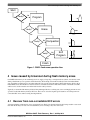
3 C90FL flash memory erase operation
The C90FL flash memory erase operation consists of multiple steps that are implemented by the C90FL flash memory
controller hardware.
1. Program: All bits in the selected flash memory block(s) are programmed to a threshold voltage (Vt) above the
program verify level (P) to allow the erase operation to begin at a consistent state.
2. Erase: The erase step will erase all bits to a threshold voltage (Vt) that is below the erase verify level (E). Since erase
is a bulk operation in which an erase pulse will move all the bits in a flash block, some of the bits will be over-erased,
in other words, below compaction verify or soft program verify level.
3. Compaction: This step moves any bits that are over-erased up to reduce column leakage of the flash array.
4. Soft Program: At the soft program step, all the bits with a threshold voltage (Vt) below the soft program verify level
will be programmed back with very low gate bias to avoid overshoot of erase verify level for any bits. As a result, when
an erase operation is completed, all the bits in the selected blocks will have their threshold voltage within a predefined
window between erase verify level (E) and soft program verify level (SP).
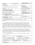
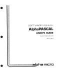
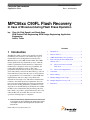
A flow diagram of these steps is shown in the figure below. In addition to the flow of the erase operation, this figure also
includes a graphical representation of the threshold voltage of the flash bits in the cells. The graphs show the threshold
voltage distribution of the flash bits after each operation in the flash cell by number of bits (#) versus the threshold voltage
(V). It shows the relative values of:
• Program verify level (P)
• Soft program level (SP)
• Erase level (E)
NOTE
Erased bits (1) have a low threshold voltage and programmed bits (0) have a high
threshold voltage.
MPC56xx C90FL Flash Recovery , Rev. 1, 02 May 2012
2
Freescale Semiconductor, Inc.
Issue caused by brownout during flash memory erase
Start
#
Verify?
No
Program
Yes
0
SP E
P
Vt
SP E
P
Vt
SP E
P
Vt
SP E
P
Vt
#
Verify?
No
Erase
Yes
0
#
Verify?
No
Compaction
0
Yes
Verify?
No
Soft
Program
Yes
#
0
Finish
Figure 1. C90FL flash erase operation flow
4 Issue caused by brownout during flash memory erase
On C90FL flash memory, if an accidental power loss, supply voltage drop, or unexpected reset (that is, a brownout) occurs
during a flash memory erase operation, the flash memory blocks being erased will most likely be left in an indeterminate
state, depending on which step was executing when the erase operation was interrupted. If the flash memory block is in an
indeterminate state, then the Error Correction Code for each flash word will not match the contents of the flash word. This
will be seen as an uncorrectable error if the flash word is read by software.
Typically, to return the flash memory block(s) being interrupted back to a working state, users can simply perform an erase
operation on the flash memory block(s). However, there are two cases that require special attention: recovering from noncorrectable ECC errors and recovering from depleted bits.
4.1 Recover from non-correctable ECC errors
A brownout during a flash memory erase operation will very likely leave the bits in the block(s) being erased in a state such
that when the block(s) are read, non-correctable ECC (error correcting code) errors will occur.
MPC56xx C90FL Flash Recovery , Rev. 1, 02 May 2012
Freescale Semiconductor, Inc.
3
Issue caused by brownout during flash memory erase
NOTE
In the C90FL flash memory, single-bit error correction and double-bit error detection
(SEC-DED) ECC code is used.
For example, if the brownout occurs during the program step in the erase operation, many flash memory pages including the
corresponding ECC bits will be left programmed. Note that all zeros is not a valid ECC codeword, and hence this will cause
non-correctable ECC errors when reading those flash memory block(s). This can also be seen if the brownout occurs after the
program step but in the middle of the erase step.
Even in this state, the flash memory block(s) can still be erased to recover. However, many flash programming tools, by
default, may read flash memory while executing the erase code from RAM before performing an erase operation. As a result,
an ECC error will be generated and hence an exception. If the flash programming tool does not have a proper exception
handler implemented, the exception may cause code execution to hang. This will cause the erase operation to fail.The tool
may include an option to not perform a read of a block prior to the erase operation2. See Example debugger erase script
(Appendix A) for a sample debugger script that performs an erase operation without first performing a read of the flash
memory.
To recover from such a state, users need to be aware of possible flash programmer tool failure for an erase operation caused
by a flash ECC exception. Users can either use the FlashErase function provided in the MPC56xx C90FL flash standard
software driver to erase the interrupted flash memory block(s), or use a Nexus/JTAG debugger script to simply toggle the
low-level flash register bits to perform the erase operation. Please refer to Example debugger erase script (Appendix A) for a
sample Lauterbach Trace32 script for erasing C90FL flash.
4.2 Recover from depleted bits
It is also possible that a brownout during the flash erase operation will leave the bits in the flash memory block(s) being
erased in an over-erased or depleted state. For instance, if the brownout occurs after the erase step, but prior to the
compaction and soft program steps are completed, it is possible that the flash bits will be left in a depleted state (very low
threshold voltage).
Depending on how depleted the bits are, excessive column leakage caused by the bits may cause the following program
operation to fail due to suppressed drain bias. In other words, there would be insufficient voltage to allow the bit to be
programmed. Note that the first step in an erase operation is a program step, and thus for this case, the erase operation to
recover the interrupted flash memory block(s) might fail. It will appear to users that the flash memory block(s) cannot be
erased and recovered.
In this case, to recover the depleted flash memory block(s), users first need to use the binary C-array FlashDepletionRecover
function provided in the MPC56xx C90FL flash standard software driver to recover the depleted bits in the flash memory
block(s). Then the erase operation must be restarted to recover the block(s). The FlashDepletionRecover function in the flash
driver is called in a similar way as any of the other binary C-array flash driver functions. Please refer to Example depletion
recovery code (Appendix B) for example code for calling this function to recover depleted blocks.
For EEPROM emulation applications, this case is handled in the MPC56xx C90FL EEPROM emulation software driver
provided by Freescale. Basically, there is brownout handling code in the FSL_InitEeprom function. If an erase operation fails
to recover the interrupted flash memory block(s), a call to FlashDepletionRecover function will be made to recover the
depleted bits, and then an erase operation will be started again to recover the interrupted flash memory block(s).
2.
Check with your flash programming tool provider for instructions to disable reads prior to an erase.
MPC56xx C90FL Flash Recovery , Rev. 1, 02 May 2012
4
Freescale Semiconductor, Inc.
Conclusion
5 Conclusion
Typically, if an erase operation is interrupted due to a brownout, simply repeating the flash erase operation will recover the
the flash memory block(s). However, special care needs to be considered for cases in which an erase operation does not
remove ECC errors and depleted bits. A generic erase should always be used initially. If the generic erase fails, the new
FlashDepletionRecover function should be used to to fix non-correctable ECC errors and bits left in a depleted state.
6 Revision history
Table 2. Revision history
Revision number
Date
1
02 May 2012
Description of changes
Substantially expanded information
throughout document and added
images. (Revision 0 not publicly
released.)
Appendix A Example debugger erase script
Here is an example script (erase_blk.cmm) that will restore a C90FL flash to a standard erased state. This is essentially the
same as the FlashErase() function of the MPC56xx C90FL flash standard software driver. This example is written for the
MPC564xL using the Lauterbach Trace32 debugger.The script is called with the values of the Low/Mid-Address Select
register value and the high-address select register value in the following manner to erase the Low Address Space block 0
(LAS0). :
do erase_blk.cmm 1 0
Here is a listing of the erase_blk.cmm script file
;lblk and hblk are inputs (corresponding to the Low/Mid-address space block
;and high-address select registers) to select which block(s) to be erased
local &mcr &peg &lblk &hblk &mcr &fdone
entry &lblk &hblk
;reset MCR
data.set ea:0xc3f88000 %long 0
data.set ea:0xc3f88000 %long 0
;enable block
data.set ea:0xc3f88010 %long &lblk
data.set ea:0xc3f88014 %long &hblk
&fdone=0
;set ERS
data.set ea:0xc3f88000 %long 0x4
;interlock write
data.set ea:0x00000000 %long 0xffffffff
;set EHV
data.set ea:0xc3f88000 %long 0x5
;wait for DONE
while &fdone==0
(
MPC56xx C90FL Flash Recovery , Rev. 1, 02 May 2012
Freescale Semiconductor, Inc.
5
&mcr=data.list(ea:0xc3f88000)
&fdone=&mcr&0x0400
)
;clear EHV
data.set ea:0xc3f88000 %long 0x4
&mcr=data.list(ea:0xc3f88000)
&peg=&mcr&0x0200
if &peg==0
print "fail"
else
print "pass"
;clear ERS
data.set ea:0xc3f88000 %long 0
Appendix B Example depletion recovery code
This listing is an example of calling the FlashDepletionRecover function from the MPC56xx C90FL flash standard software
driver to recover depleted blocks of the flash memory.
#include
#include
#include
"ssd_types.h"
"ssd_c90fl.h"
"normaldemo.h"
extern const unsigned int FlashInit_C[];
extern const unsigned int FlashDepletionRecover_C[];
extern const unsigned int SetLock_C[];
/* Assign function pointers */
pFLASHINIT
pFlashInit
= (pFLASHINIT)
FlashInit_C;
pSETLOCK
pSetLock
= (pSETLOCK)
SetLock_C;
pFLASHDEPLETIONRECOVER
pFlashDepletionRecover
= (pFLASHDEPLETIONRECOVER)
FlashDepletionRecover_C;
SSD_CONFIG ssdConfig = {
C90FL_REG_BASE,
MAIN_ARRAY_BASE,
0,
SHADOW_ROW_BASE,
SHADOW_ROW_SIZE,
0,
0,
0,
0x10,
FALSE
};
/*
/*
/*
/*
/*
/*
/*
/*
/*
/*
UINT32 main(void)
{
UINT32 returnCode;
BOOL
UINT32
UINT32
UINT32
c90fl control register base */
base of main array */
size of main array */
base of shadow row */
size of shadow row */
block number in low address space */
block number in middle address space */
block number in high address space */
page size */
debug mode selection */
/* Return code from each SSD function. */
shadowFlag;
lowEnabledBlocks;
midEnabledBlocks;
highEnabledBlocks;
/*
/*
/*
/*
shadow select flag
selected blocks in
selected blocks in
selected blocks in
*/
low space */
middle space */
high space */
/*========================= Initialize Part =========================*/
returnCode = pFlashInit( &ssdConfig );
if ( C90FL_OK != returnCode )
{
ErrorTrap(returnCode);
}
/* Unlock all main array blocks */
MPC56xx C90FL Flash Recovery , Rev. 1, 02 May 2012
6
Freescale Semiconductor, Inc.
returnCode = pSetLock( &ssdConfig,
if ( C90FL_OK != returnCode )
{
ErrorTrap(returnCode);
}
returnCode = pSetLock( &ssdConfig,
if ( C90FL_OK != returnCode )
{
ErrorTrap(returnCode);
}
returnCode = pSetLock( &ssdConfig,
if ( C90FL_OK != returnCode )
{
ErrorTrap(returnCode);
}
returnCode = pSetLock( &ssdConfig,
if ( C90FL_OK != returnCode )
{
ErrorTrap(returnCode);
}
returnCode = pSetLock( &ssdConfig,
if ( C90FL_OK != returnCode )
{
ErrorTrap(returnCode);
}
LOCK_LOW_PRIMARY, 0, FLASH_LMLR_PASSWORD);
LOCK_LOW_SECONDARY, 0, FLASH_SLMLR_PASSWORD);
LOCK_MID_PRIMARY, 0, FLASH_LMLR_PASSWORD);
LOCK_MID_SECONDARY, 0, FLASH_SLMLR_PASSWORD);
LOCK_HIGH, 0, FLASH_HLR_PASSWORD);
/*===== Deletion recover main array space ========================*/
shadowFlag = FALSE;
/* Select the all main array blocks */
lowEnabledBlocks = 0xffffffff;
midEnabledBlocks = 0xffffffff;
highEnabledBlocks = 0xffffffff;
returnCode = pFlashDepletionRecover( &ssdConfig, shadowFlag, lowEnabledBlocks,
midEnabledBlocks, highEnabledBlocks, NULL_CALLBACK );
if ( C90FL_OK != returnCode )
{
ErrorTrap(returnCode);
}
}
/*=========== DEMO FINISHED =============================*/
/* DEMO PASSED */
return ((UINT32)DEMO_PASS);
/*******************************************************************
| function implementations (scope: module-local)
|------------------------------------------------------------------*/
/* Error trap function */
void ErrorTrap(UINT32 returnCode)
{
VUINT32 failedReason;
failedReason = returnCode;
}
while(1)
{
;
}
The function pointers for the driver functions are defined in “ssd_c90fl.h” as below:
typedef UINT32 (*pFLASHINIT) ( PSSD_CONFIG pSSDConfig );
typedef UINT32 (*pFLASHDEPLETIONRECOVER) (
PSSD_CONFIG pSSDConfig,
BOOL shadowFlag,
UINT32 lowEnabledBlocks,
UINT32 midEnabledBlocks,
MPC56xx C90FL Flash Recovery , Rev. 1, 02 May 2012
Freescale Semiconductor, Inc.
7
UINT32 highEnabledBlocks,
void (*CallBack)(void)
);
typedef UINT32 (*pSETLOCK) (
PSSD_CONFIG pSSDConfig,
UINT8 blkLockIndicator,
UINT32 blkLockState,
UINT32 password
);
Appendix C References
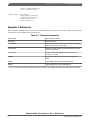
These documents, including each device's reference manual and data sheet, should also be referred to when working with the
flash modules. All are available at www.freescale.com.
Table C-1. Reference documents
MPCxxxxRM
Device reference manual
MPCxxxxx
Device data sheet
User manual1
MPC56xx C90FL Flash Standard Software Driver for Single
Module Flash (version 1.0.0 or later)
User manual1
MPC5674F_5676R_C90FL Flash Standard Software Driver
(version 1.0.0 or later)
User manual1
MPC56xx C90FL EEPROM Emulation Software Driver
(version 1.0.1 or later)
AN4365
"Qorivva MPC56xx Flash Programming Through Nexus/
JTAG"
EB618
"Typical Data Retention for Nonvolatile Memory"
EB619
"Typical Endurance for Nonvolatile Memory"
1. The user manual is installed in the directory with the flash driver and example code when the software driver is installed.
MPC56xx C90FL Flash Recovery , Rev. 1, 02 May 2012
8
Freescale Semiconductor, Inc.
How to Reach Us:
Home Page:
www.freescale.com
Web Support:
http://www.freescale.com/support
USA/Europe or Locations Not Listed:
Freescale Semiconductor
Technical Information Center, EL516
2100 East Elliot Road
Tempe, Arizona 85284
+1-800-521-6274 or +1-480-768-2130
www.freescale.com/support
Europe, Middle East, and Africa:
Freescale Halbleiter Deutschland GmbH
Technical Information Center
Schatzbogen 7
81829 Muenchen, Germany
+44 1296 380 456 (English)
+46 8 52200080 (English)
+49 89 92103 559 (German)
+33 1 69 35 48 48 (French)
www.freescale.com/support
Japan:
Freescale Semiconductor Japan Ltd.
Headquarters
ARCO Tower 15F
1-8-1, Shimo-Meguro, Meguro-ku,
Tokyo 153-0064
Japan
0120 191014 or +81 3 5437 9125
[email protected]
Asia/Pacific:
Freescale Semiconductor China Ltd.
Exchange Building 23F
No. 118 Jianguo Road
Chaoyang District
Beijing 100022
China
+86 10 5879 8000
[email protected]
Document Number: AN4521
Rev. 1, 02 May 2012
Information in this document is provided solely to enable system and software
implementers to use Freescale Semiconductors products. There are no express or implied
copyright licenses granted hereunder to design or fabricate any integrated circuits or
integrated circuits based on the information in this document.
Freescale Semiconductor reserves the right to make changes without further notice to any
products herein. Freescale Semiconductor makes no warranty, representation, or
guarantee regarding the suitability of its products for any particular purpose, nor does
Freescale Semiconductor assume any liability arising out of the application or use of any
product or circuit, and specifically disclaims any liability, including without limitation
consequential or incidental damages. "Typical" parameters that may be provided in
Freescale Semiconductor data sheets and/or specifications can and do vary in different
applications and actual performance may vary over time. All operating parameters,
including "Typicals", must be validated for each customer application by customer's
technical experts. Freescale Semiconductor does not convey any license under its patent
rights nor the rights of others. Freescale Semiconductor products are not designed,
intended, or authorized for use as components in systems intended for surgical implant
into the body, or other applications intended to support or sustain life, or for any other
application in which failure of the Freescale Semiconductor product could create a
situation where personal injury or death may occur. Should Buyer purchase or use
Freescale Semiconductor products for any such unintended or unauthorized application,
Buyer shall indemnify Freescale Semiconductor and its officers, employees, subsidiaries,
affiliates, and distributors harmless against all claims, costs, damages, and expenses, and
reasonable attorney fees arising out of, directly or indirectly, any claim of personal injury
or death associated with such unintended or unauthorized use, even if such claims alleges
that Freescale Semiconductor was negligent regarding the design or manufacture of
the part.
RoHS-compliant and/or Pb-free versions of Freescale products have the functionality and
electrical characteristics as their non-RoHS-complaint and/or non-Pb-free counterparts.
For further information, see http://www.freescale.com or contact your Freescale
sales representative.
For information on Freescale's Environmental Products program, go to
http://www.freescale.com/epp.
Freescale™ and the Freescale logo are trademarks of Freescale Semiconductor, Inc.
All other product or service names are the property of their respective owners.
© 2011–2012 Freescale Semiconductor, Inc.