1
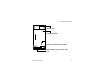
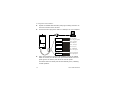
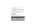
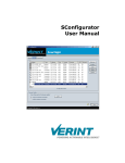
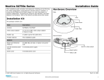
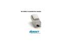
S1100w Installation Guide S1100w Installation Guide Verint Video Solutions © 2005 Verint Systems Inc. All rights reserved. By providing this document, Verint Systems Inc. is not making any representations regarding the correctness or completeness of its contents and reserves the right to alter this document at any time without notice. Verint, Actionable Intelligence, BehaviorTrack, Dellis, HealthCheck, Lanex, Loronix, Loronix Video Manager, MotionTrack, microDVR, nDVR, netDVR, Nextiva, Powering Actionable Intelligence, SmartSight, and Video Manager are trademarks of Verint Systems Inc., its subsidiaries or affiliates. All other registered trademarks, trademarks, and any associated logos are the properties of their respective owners. Published by: Verint Video Solutions 1800 Berlier Street Laval (Quebec) Canada H7L 4S4 www.verint.com/videosolutions Publication date: May 3, 2005 Warning: If you connect multiple devices on the same 24V AC power supply, always wire them the same way: The red power wires of all devices must be on the same power supply terminal. Since the black power wire of the device is internally connected to its chassis (earth), swapping the power connection scheme from device to device will short out the AC power supply. Warning: You can install third-party equipment with an earth-referenced power input on the same power source as the devices. To do so, you must connect the earth-referenced terminal of the equipment to the same AC terminal as the black wire of the devices. Failing to do so will short out the AC power supply. Verint Video Solutions iii T M Black Stat us Red T M Black Stat us T M Red Black Stat us Red Third-party equipment Isolated 24V AC AC main iv Verint Video Solutions Contents Preface .....................................................................................vii Who Should Read this Guide .................................................. viii How to Use this Guide .......................................................... viii About Us .............................................................................. ix Chapter 1 Overview ................................................................. 1 About the S1100w ..................................................................2 Shipment ...............................................................................3 Casing Description ..................................................................4 Chapter 2 Configuration and Installation ................................ 7 Overview ...............................................................................8 Configuration .........................................................................9 Point-to-Point Connection ....................................................... 16 Installation of the Transmitter ................................................ 18 Installation of an Antenna ...................................................... 21 Status LED ........................................................................... 22 Index ....................................................................................... 25 Verint Video Solutions v Contents Edge Device Description Form .................................................. 27 vi Verint Video Solutions Preface The S1100w Installation Guide explains how to configure and install the NextivaTM S1100w wireless video transmitters. Verint Video Solutions vii Preface Who Should Read this Guide This guide is intended for engineers and technicians who will install the S1100w edge devices. It provides basic information on how to configure and install the devices. This guide assumes that you are familiar with: Installation and manipulation of electronic equipment General use of computers Basic network concepts and practices Radio frequency (RF) regulations Microsoft Windows operating systems How to Use this Guide The S1100w Installation Guide is divided into the following chapters: 1. Overview—Provides a brief description of the features of the S1100w transmitter and an illustration of its casing. 2. Configuration and Installation—Presents the configuration and installation procedures of the transmitter. An index and a device description form complete the guide. viii Verint Video Solutions S1100w Installation Guide In addition to this guide, the following documentation is also available: S1100w User Manual—Contains conceptual information on the configuration, installation, and operation of the S1100w edge devices. SConfigurator User Manual—Presents the instructions on how to use a proprietary Verint Video Solutions software to configure the edge device, connect it to other devices, and update its firmware. Release Notes—Contain information about S1100w upgrades and known issues still under investigation, as well as a description of features not covered in this version of the documentation. All these documents are contained on the SmartSight Utilities CD shipped with the device. About Us Verint Systems (NASDAQ: VRNT) is a leading global provider of video security, surveillance and business intelligence solutions. Verint Video Solutions transform digital video into actionable intelligence: timely, mission-critical insights for faster, more effective decisions. Today, more than 1000 companies in 50 countries use Verint Systems solutions to enhance security, boost operational efficiency, and fuel profitability. Verint Video Solutions ix Preface Web Site For information about the Nextiva line of products, visit www.verint.com/ videosolutions. To download application notes and user documentation, as well as request the latest versions of firmware and software, you need access to the Verint Video Solutions partner extranet. To register, go to www.verint.com/smartsight/support. The data sheets of the Nextiva edge devices are also available directly at www.verint.com/smartsight/support. Support If you encounter any type of problem after reading this manual, contact your local distributor or Verint Video Solutions representative. You can also use the following sections on the Verint Video Solutions partner extranet to find the answers to your questions: SmartSight FAQ SmartSight Requests SmartSight My Account x Verint Video Solutions S1100w Installation Guide Verint Video Solutions technical support personnel is available to help you use your Nextiva edge devices and the related software: By phone: 1 888 494-7337 (North America) or +1 450 686-9000 Monday to Friday, from 8:30 to 17:30 EST By fax: +1 450 686-0198 Verint Video Solutions xi xii Verint Video Solutions 1 Overview The S1100w is the industry’s first wireless video transmitter allowing digital video transmission over multiple license-free bands. It delivers high-quality MPEG-4-based video at 30 frames per second in NTSC (25 in PAL) over local and wide area networks (LANs and WANs). This wireless server is built on open standards to provide long-term investment protection. Note: The S1100w transmitters require professional installation. Verint Video Solutions 1 1: Overview About the S1100w The S1100w leverages the SPCF MAC (Media Access Control) protocol, which resolves the “hidden node,” quality of service, range, and security problems inherent to 802.11 wireless networking products. The S1100w covers the 2.4 GHz and 5 GHz frequency bands in North America and Europe. You can purchase an S1100w transmitter with a motion track device (S1100w-MT). It provides the most accurate, cost effective wireless outdoor motion tracking capability available today. It incorporates adaptive digital processing technology to achieve highly sensitive detection in a wide range of operating environments with very low false alarm rates. For more information, refer to the S1100w User Manual. Each transmitter is configured to interface, right out of the box, with the most popular camera data port configuration (4800 baud, 8 data bits, no parity, 1 stop bit). 2 Verint Video Solutions S1100w Installation Guide Shipment Your S1100w shipment contains the following items: The requested transmitter, which comes with an integrated patch antenna (with a gain of 8.5 dBi in the 2.4 GHz band or 13 dBi in the 5 GHz band) A wall mount bracket set, already installed on the transmitter A pole mount bracket set, including stainless steel clamps A cable assembly for video, power, and serial port (CAB9P) The SmartSight Utilities CD containing the documentation and release notes for the device as well as the SConfigurator application This installation guide The shipment may also contain the following options: A high-gain antenna Warning: When choosing an antenna, you must ensure that the combined transmission power of the transmitter and antenna does not exceed the maximum value established by your country’s regulations. For more information, refer to the S1100w User Manual. A junction box (JBOX) Verint Video Solutions 3 1: Overview An alarm/audio cable assembly (CAB8P) A power supply Note: If you are using a power supply other than those supplied by Verint Video Solutions, you need to ensure that they have a minimum capacity of 1A (for 12V DC) or 30 VA (for 24V AC). Casing Description The S1100w electronics are enclosed in a weather-tight cast aluminum module. All cable entries are mounted on the underside of the module to maintain its weatherproof properties. The front panel integrates one bicolor visual indicator that illustrates the operational state of the transmitter. 4 Verint Video Solutions S1100w Installation Guide Antenna port Integrated antenna Status indicator Status Auxiliary connector (alarm, audio) Main connector (video, power, serial port) Verint Video Solutions 5 6 Verint Video Solutions 2 Configuration and Installation The steps required to prepare your S1100w transmitter for operation are: Basic configuration, mainly for communication and serial connection Establishment of a point-to-point connection between the S1100w transmitter and a receiver, if required Physical installation in its final location Verint Video Solutions 7 2: Configuration and Installation Overview In a wireless application, the order in which you configure the devices (either the first time or later when they are installed in the field) is critical if you do not want to lose access to them. You should then: 1. Configure the devices starting with the farthest (in terms of number of RF hops) from the computer used in the setup process. 2. One step at a time, get closer to the computer. The S1100w transmitters require the presence of an S3100 outdoor wireless bridge to send their digitized data to a wired network. The minimum hardware and software requirements for the host computer needed to configure the edge device are: An Ethernet network card A serial port (not through a USB converter) Windows 2000 Service Pack 2 or higher, or Windows XP 8 Verint Video Solutions S1100w Installation Guide Configuration The first step in preparing an S1100w transmitter is setting its wireless, IP, and serial port parameters using the embedded command line interface (CLI). Write down this information in the form located at the end of the guide, on page 27. To configure the transmitter, you need the proprietary SConfigurator tool. It is included on the SmartSight Utilities CD shipped with your device; you can also find its latest version on the Verint Video Solutions extranet (Technical Support > Downloads > Firmware Upgrades). You have to copy its executable file to the hard disk of your computer. For more information about the CAB9P cable supplied with your order, refer to the S1100w User Manual. To prepare the transmitter for configuration: 1. In a lab, unpack the S1100w transmitter and its associated S3100 outdoor wireless bridge and place them on a table. 2. Connect the external antenna on the S3100 and optionally on the S1100w. Warning: To avoid material damages, you must never power any two devices while their antennas are facing one another with a distance of less than 10 feet (3 meters). Verint Video Solutions 9 2: Configuration and Installation 3. Unpack the CAB9P cable assembly and plug its mating connector on the main connector of the S1100w. 4. Connect the DB-9 plug of the cable to a COM port on your computer. Red and black Status 5. Red - VIN (power) Black - VIN_return (power) Green and black Green - CTS (Rx+) Black - RXD (Rx-) Yellow and black Yellow - TXD (Tx+) Black - RTS (Tx-) Blue and black Blue - CAM4/MON Black - Video ground Brown and black Brown - Signal ground Black - Signal ground Power the transmitter using the red and black wires of the CAB9P cable. In 12V DC, the red wire is for input and the black wire is for power ground. In 24V AC, both wires are used for power. The status LED turns steady red and then flashes green, indicating normal operation. 10 Verint Video Solutions S1100w Installation Guide To set the parameters: 1. Start the SConfigurator software. The SConfigurator window appears. 2. From the General tab, click Console. The Verint Console window appears. 3. In the Connect using list, select the COM port used to communicate with the transmitter. Verint Video Solutions 11 2: Configuration and Installation 4. Click Connect. The CLI main menu appears. 12 Verint Video Solutions S1100w Installation Guide 5. Select Wireless Communication, then press Enter. The Wireless Communication menu appears. 6. Change the wireless passkey of the transmitter. The case-sensitive passkey must have exactly 16 characters (if the format is string—default) or 32 digits (if hexadecimal). For the wireless connection to be secure, do no enter a known name (like a street name), but instead use a mix of digits and letters. Furthermore, do not disclose the passkey. The connection security is based on the secrecy and uniqueness of the passkey. 7. Select the country of operation of the transmitter. Verint Video Solutions 13 2: Configuration and Installation 8. Press p to go back to the CLI main menu. 9. Select Network, then press Enter. The Network menu appears. 10. Set the local IP address, subnet mask, and gateway, as required. 11. Go back to the CLI main menu. 14 Verint Video Solutions S1100w Installation Guide 12. Select Serial Port > RS-232/422/485. The RS-232/422/485 menu appears. 13. Set the parameters to match those of the target equipment (for instance, a camera or dome). 14. Go back to the CLI main menu. 15. Save the changes by pressing s, then Enter. 16. Exit the CLI by pressing q, then Enter. The configuration of the S1100w is now complete. 17. Configure the outdoor wireless bridge for a point-to-multipoint application. For the complete procedure, refer to the S3100 Installation Guide. Verint Video Solutions 15 2: Configuration and Installation 18. Using SConfigurator, ensure that the S1100w and its wireless bridge communicate well together: In the Units tab, the S1100w transmitter should be hierarchically positioned under its S3100. In the Link Status pane of the S3100, the S1100w transmitter should be in the Clients/Slaves list. Ensure that there is end-to-end video transmission in the lab before installing the devices in their final location. Point-to-Point Connection To allow video display on a monitor in a point-to-point context, you have to create a fixed connection between the S1100w transmitter and an S1500e or S1600e receiver. Typically, both devices sit on the same IP subnet as SConfigurator and have the same VSIP port; to access other devices, refer to the device discovery section in the SConfigurator User Manual. Note: The receiver must be running firmware version 3.10 or higher. For more information about the connection procedure, refer to the “Managing Connections” chapter, in the SConfigurator User Manual. 16 Verint Video Solutions S1100w Installation Guide To perform a point-to-point connection: 1. Start SConfigurator. 2. In the Units tab, discover the desired devices. The discovered devices appear in the Units box. 3. Select the Connections tab, then click Add. The Connection Creator window appears. 4. Select a transmitter in the left column and a receiver in the right one. In the Transmitters column, you have access to the two encoders of each input; the video stream is the same for both. Verint Video Solutions 17 2: Configuration and Installation 5. To disable I/O data transmission (for example, alarms), clear Forward I/O. 6. To disable serial port data transmission (like PTZ commands), clear Forward Serial Port Data. 7. To enable audio between the devices, ensure that Enable Audio is checked, then select the audio mode. 8. Click Connect. You should now have video on the monitor connected to the receiver. Installation of the Transmitter When the S1100w is properly configured, it is ready to be installed. Warning: Always mount the transmitter with the mating connectors pointing downwards. Otherwise moisture may penetrate the device; the associated repair costs would not be covered by the warranty. When installing colocated wireless systems, you have to take into account the following distance limitations: 18 To avoid material damages, you must never power any two devices while their antennas are facing one another with a distance of less than 10 feet (3 meters). Verint Video Solutions S1100w Installation Guide With different frequency bands or with non-adjacent channels in the same band, two devices can be side by side with no minimum distance between them. If using adjacent channels, refer to the “Separation Between Devices Using Adjacent Channels” appendix in the S1100w User Manual for the minimum distances to respect. To install an S1100w transmitter: 1. To install the S1100w on a light pole or mast, use the supplied pole mount brackets and stainless steel clamps. For wall mounting, use the side brackets already installed on the transmitter. 2. If you are installing the S1100w equipment in a lightning prone environment or in a site where large AC mains power fluctuations are a common occurrence, add additional external surge protection to all vulnerable connections. Vulnerable connections are those that run for a long distance between the S1100w and the connected equipment. For more information, refer to the “Surge Protection” appendix in the S1100w User Manual. 3. If the S1100w will be directly exposed to the sun in an environment likely to reach 122°F (50°C), install a sun shield. 4. If required, install an external antenna (see page 21). Verint Video Solutions 19 2: Configuration and Installation 5. Apply silicone grease on the mating connector of the CAB9P cable and on the main connector of the device. For the detailed procedure, refer to the leaflet shipped with the cable. 6. Connect the CAB9P cable to the S1100w. To properly install the cable connector on the transmitter, you have to turn until you feel a positive click. 7. Plug the BNC video connector of the CAB9P cable on the target device. 8. Using the CAB9P cable, perform the serial connection to the target device. For example, here is an RS-422/485 4-wire setup: Tx+ Tx- Rx+ Rx- Tx+ Tx- Rx+ Gnd Rx- Gnd For the detailed description of the RS-422/485 connections, refer to the “Configuring and Installing the Device” chapter in the S1100w User Manual. 20 Verint Video Solutions S1100w Installation Guide 9. If you are using a junction box, route all wires to it first; then route the wires from the box to the target device. 10. Power up the transmitter. Installation of an Antenna If you bought a high gain antenna, install it after the S1100w is in place. The antennas provided by Verint Video Solutions are designed to be mounted on a mast or pole of 2–3 inch (5–7.5 cm) diameter. To install the antenna: 1. Install the antenna above the S1100w. If you bought your antenna from Verint Video Solutions, use the supplied pole mount bracket. 2. Screw the SMA connector of the antenna cable to the S1100w main antenna port and tighten it with a 0.25-inch (0.6 cm) wrench. Warning: Do not over-tighten to avoid damaging the connector. The recommended torque is 8 lb-in. (100 N-cm). You could use a calibrated SMA torque wrench (for instance, from the Pasternack company, available at www.pasternack.com). Verint Video Solutions 21 2: Configuration and Installation 3. Apply two or three layers of electrical tape around all RF (radio frequency) connections. The antenna cable and connectors are weather-tight; however, vibration caused by the wind will over time loosen the connectors and reduce the efficiency of the gaskets. The electrical tape will prevent this situation. 4. Carefully align the antennas of the S1100w and outdoor wireless bridge so that they have a clear RF line of sight. 5. To improve the signal level between both devices, use the antenna alignment utility from SConfigurator. Status LED The status LED is a bicolor (green-red) LED that provides detailed information on the current state of the transmitter. Condition Indication Steady red The device is powering up. Flashing red (1 sec. intervals) The IP address of the device is already assigned to another device in the network. Flashing green (3 sec. intervals) The firmware has started, but RF communication is not established. Flashing green (1 sec. intervals) The firmware has started, RF communication is established, but no video/serial* data is transmitted. 22 Verint Video Solutions S1100w Installation Guide Condition Indication Flashing green (0.2 sec. intervals) The firmware has started, RF communication is established, and video/serial* data is transmitted. Three consecutive red blinks No video source is detected and no video is every 2 sec. transmitted. Flashing green-red (1 sec. intervals) The device is undergoing a firmware update. Flashing red (0.1 sec. intervals) The device is being identified. * At least one of them must be transferred to get the LED condition. The following power-up conditions are abnormal: LED not lit—Check the power supply and cabling. If power is available and the LED stays off, call Verint Video Solutions technical support for assistance. Steady red LED—There is an internal error that prevents the device from starting normally. Power down the device, wait 30 seconds, then power it up. If the condition persists, call Verint Video Solutions technical support. Flashing green-red LED not during a firmware update—The device requires a new firmware with a serial connection. Verint Video Solutions 23 24 Verint Video Solutions Index Numerics 24V AC power connection warning iii A abnormal power-up condition 23 address, IP 14 antenna distance between 18 external 21 integrated 3 C CAB9P cable 10 camera data port configuration 2 casing of the device 4 CD, Utilities ix characteristics of the device 2 CLI (command line interface) main menu 12 COM port 11 communication between S3100 and S1100w 16 computer requirements 8 configuration camera data port 2 device 9–15 order, in the wireless cell 8 Verint Video Solutions connection point-to-point 16 power iii SConfigurator and device 11 serial device and transmitter 20 D description form 27 distance between antennas 18 E enclosure of the device 4 equipment list 3 external antenna 21 F features of the device 2 form, device description 27 I installation antenna 21 device 18–21 integrated antenna 3 IP address 14 25 Index L RF (radio frequency) parameters 13 LED, status 22 list of equipment 3 S M main menu of the CLI 12 N network parameters 14 O options, when ordering a device 3 order in the configuration process 8 P parameters, device 12–15 passkey, wireless 13 point-to-point connection 16 power connection, warning on 24V AC iii power requirement 4 power up conditions 23 protection, surge 19 R radio frequency (RF) parameters 13 receiver device 16 requirements computer 8 power 4 26 SConfigurator checking communication between devices 16 console 11 creating a connection 17 serial port parameters 15 shipment list 3 SmartSight Utilities CD ix status LED 22 support, technical x surge protection 19 T technical support x U Utilities CD ix V Verint Video Solutions web site x W web site, Verint Video Solutions x wireless parameters 13 Verint Video Solutions Edge Device Description Form Verint Video Solutions 27 Edge Device Description Form During configuration, write down the following settings that may be required by Verint Video Solutions technical support for troubleshooting: System Firmware version VSIP VSIP port Wireless Average signal RF channel RF bit rate Wireless passkey Video Video bit rate Frame rate Resolution Network IP address Gateway Subnet mask Security 28 SSL passkey Verint Video Solutions Verint Video Solutions 1800 Berlier Street Laval (Quebec) Canada H7L 4S4