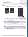
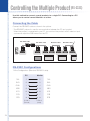
1
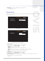
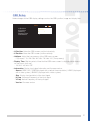
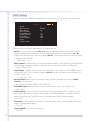
User’s Manual L421AL**** Make sure to read the Safety Precautions before using the product. Keep the User’s Manual(CD) handy so that you can refer to it whenever you want. Contents Safety Precaution . . . . . . . . . . . . . . . . . . . . . . . 02 Electrical Power Related Precautions . . . . . . . . . . . . . . . . . . . . . . . Precautions in installing the Product . . . . . . . . . . . . . . . . . . . . . . . Precautions in Using the Product . . . . . . . . . . . . . . . . . . . . . . . . . Precautions On Cleaning . . . . . . . . . . . . . . . . . . . . . . . . . . . . . 02 03 04 05 Getting Started . . . . . . . . . . . . . . . . . . . . . . . . 06 Checking the Control Panel . . . . . . . . . . . . . . . . . . . . . . . . . . . . 06 Checking the Connection Panel . . . . . . . . . . . . . . . . . . . . . . . . . . 07 Using the Remote Control . . . . . . . . . . . . . . . . . . . . . . . . . . . . . 08 Inserting the Button-type Battery in the Remote Control . . . . . . . . . . . . . . . . . . . . 09 Connecting . . . . . . . . . . . . . . . . . . . . . . . . . . 10 Connecting a Monitor to External Devices . . . . . . . . . . . . . . . . . . . . 10 To a PC . . . . . . . . . . . . . . . . . . . . . . . . . . . . . . . . . . . . . . . . . . . . 10 To a DTV Set Top Box . . . . . . . . . . . . . . . . . . . . . . . . . . . . . . . . . . . . 11 To external AV devices . . . . . . . . . . . . . . . . . . . . . . . . . . . . . . . . . . . . 11 When connecting multiple Monitors . . . . . . . . . . . . . . . . . . . . . . . . 12 Connecting the RGB Splitter . . . . . . . . . . . . . . . . . . . . . . . . . . . . . . . . . Connecting the HDMI Splitter . . . . . . . . . . . . . . . . . . . . . . . . . . . . . . . . . Connecting the RS-232C In/Out Port . . . . . . . . . . . . . . . . . . . . . . . . . . . . . Plug the Power Cord to the outlet. . . . . . . . . . . . . . . . . . . . . . . . . . . . . . . 12 12 13 13 Selecting the Source . . . . . . . . . . . . . . . . . . . . . 14 Source List . . . . . . . . . . . . . . . . . . . . . . . . . . . . . . . . . . . . . 14 Setting . . . . . . . . . . . . . . . . . . . . . . . . . . . . . 15 On-Screen Menu Navigation . . . . . . . . . . . . . . . . . . . . . . . . . . . . 15 How to adjust the OSD (On Screen Display) . . . . . . . . . . . . . . . . . . . 16 Setting the Menu . . . . . . . . . . . . . . . . . . . . . . . . . . . . . . . . . . 17 Picture Setup . . . . . . . . . . . . . . . . . . . . . . . . . . . . . . . . . . . . . . . . . Screen Setup . . . . . . . . . . . . . . . . . . . . . . . . . . . . . . . . . . . . . . . . . OSD Setup . . . . . . . . . . . . . . . . . . . . . . . . . . . . . . . . . . . . . . . . . . Utility Setup . . . . . . . . . . . . . . . . . . . . . . . . . . . . . . . . . . . . . . . . . . Multivision Setup . . . . . . . . . . . . . . . . . . . . . . . . . . . . . . . . . . . . . . . 17 19 21 22 24 User Menu . . . . . . . . . . . . . . . . . . . . . . . . . . . 25 Automatic setting the MULTIVISION menu (For 2 by 2) . . . . . . . . . . . . . . 25 0ii User's Manual Controlling the Multiple Product (RS-232C) . . . . . . . . . . 26 Connecting the Cable . . . . . . . . . . . . . . . . . . . . . . . . . . . . . . . . . . . . . RS-232C Configurations . . . . . . . . . . . . . . . . . . . . . . . . . . . . . . . . . . . Communication Parameter . . . . . . . . . . . . . . . . . . . . . . . . . . . . . . . . . . Transmission Protocol . . . . . . . . . . . . . . . . . . . . . . . . . . . . . . . . . . . . . Receiving Protocol . . . . . . . . . . . . . . . . . . . . . . . . . . . . . . . . . . . . . . Command Reference List . . . . . . . . . . . . . . . . . . . . . . . . . . . . . . . . . . . 26 26 27 27 27 28 Troubleshooting . . . . . . . . . . . . . . . . . . . . . . . . 32 No image is displayed. . . . Screen color is abnormal. . . Images look abnormal. . . . After-image remains. . . . . . . . . . . . . . . . . . . . . . . . . . . . . . . . . . . . . . . . . . . . . . . . . . . . . . . . . . . . . . . . . . . . . . . . . . . . . . . . . . . . . . . . . . . . . . . . . . . . . . . . . . . . . . . . . . . . . 32 32 33 33 Specifications . . . . . . . . . . . . . . . . . . . . . . . . . 34 L421ALN*** . . . . . . . . . . . . . . . . . . . . . . . . . . . . . . . . . . . . . . PC Mode – Preset Mode . . . . . . . . . . . . . . . . . . . . . . . . . . . . . . Power Indicator . . . . . . . . . . . . . . . . . . . . . . . . . . . . . . . . . . . Accesories . . . . . . . . . . . . . . . . . . . . . . . . . . . . . . . . . . . . . . 34 35 35 35 User's Manual 01 Safety Precaution Please read these safety precautions carefully before using the product. This indicates that there is a possibility of serious personal injury or loss of life if the operating procedure is not followed correctly. This indicates that there is a possibility of personal injury or damage to the product if the operating procedure is not followed correctly. Electrical Power Related Precautions • Make sure to plug the power cord until it is firmly inserted. - If the power cord is not plugged completely, a fire could occur. • Do not use a damaged power cord, plug, and loose outlet. - There is a risk of fire and electric shock. • Do not touch the power plug with wet hands. - You may be electrocuted due to excessive moisture. • Do not overload a single outlet with several extension cords, electrical appliances or electrical heaters. - Abnormal heat or a fire could occur. • Do not bend, pull the power cord or damage the cable by pressing with a heavy object. - Damaged power cord may cause a fire or electric shock. • Make sure to connect the power cable to the grounded current. - You may be electrocuted or injured. • Use the rated voltage only. - The product can be damaged, or you may be electrocuted. • In the presence of thunder and lightning, never touch the power cord and signal cable. - There is a serious danger of electric shock. • Do not insert a conductor (like metal chopsticks) into one end of the power cable while the other end is connected to the input terminal on the wall. - You may be electrocuted. • Do not touch the power cable right after plugging into the wall input terminal. You may be electrocuted. • The power supply cord is used as the main disconnection device. Ensure that the socket-outlet is easily accessibly after installation. • Remove dust around the cord pin or the outlet. - Dusty power plug may cause a fire. • Pull out the power cord by the plug, not by the cable. - Damaged power cord may cause a risk or electric shock. 02 User's Manual Precautions in installing the Product • Keep the power cord or the product away from heat sources like electrical heaters. - Doing so may cause a fire or electric shock. • Keep the packing anti-moisture material or vinyl packing out of the reach of children. - Anti-moisture material is harmful if swallowed. If swallowed by mistake, force the patient to vomit and visit the nearest hospital. Vinyl packing can also cause suffocation. • Do not install in a narrow and badly ventilated place such as on a shelf or a closet. - There is a risk of a fire by the increase of internal temperature. • Do not install in a vehicle or near dust, moisture, oil, smoke and water(rainwater). - There is a risk of a fire and electric shock. • Do not use the product in a location with high humidity. - Failure to do so may expose moisture to the internal part that may shorten the product life and cause a fire. • Allow more than two persons lift and carry the product safely. - If the product is dropped, a personal injury or damage to the product could occur. • Do not install in an unstable location such as a shaky shelf, a slanted floor or a location exposed to vibration. The product may fall and hurt children. - Install in a flat, stable place to prevent the heavy front part from being weighted forward. • Avoid the direct sunlight. - Failure to do so may shorten the product life and cause a danger of fire. • When moving the product, make sure to turn off the power and disconnect the power plug and cables between the products. - Failure to do so may damage the cord and cause a danger of fire and electric shock. • Do not leave the power or signal cable unattended on the pathway. - The passerby can falter which can cause electric shock, fire, product breakdown or injury. • For ventilation, keep a certain distance (more than 10cm) from the wall. - Failure to do so may cause a temperature rise between the wall and the product and cause a fire. • Do not block the ventilation opening with a table cloth or curtain. - The product can be deformed or a fire can occur due to overheating inside the product. • Do not use the product near a humidifier. - There is a danger of a fire or electric shock. • Install the product where no EMI(electromagnetic interference) occurs. User's Manual 03 Precautions in Using the Product • When a fixed image is displayed for an extended period of time, after-images or spots may appear. - When the product is not in use for a long time, set the power saving mode or turn on the screen saver on a PC. • If the product makes an abnormal sound, smell or smokes, unplug the power cord immediately and request service. - There is a danger of fire and electric shock. • Do not place a liquid container such as a flower vase, plants, drinks, cosmetics and medicines on the product. - If the water enters the product, a fire or electric shock may occur. • Do not allow children to hang onto or climb the product. - The product tip-over may cause a personal injury or death. • Do not place heavy objects, toys or snacks that are favored by children on the product. - Children may be hurt or die by the falling objects or the product tip-over. • Prevent children from swallowing batteries and keep them away from the reach of children. - If the battery is swallowed by children, consult physician immediately. • Do not put a candle, mosquito incense, cigarette, or ashtray on the product. - There is a danger of fire. • Do not use or keep an inflammable spray and materials near the product. - There is a danger of fire and explosion. • If a gas leaks, do not touch the product or power cord. Instead, ventilate immediately. - A spark may cause an explosion and fire. • Pull out the power plug when the product is not in use or unattended for an extended period of time. - If dust is accumulated, overheating, fire, electric shock and electric leakage may outbreak. • Do not drop or impart any shock to the product. - There is a danger of a fire and electric shock. • If the product is dropped or its case is damaged, turn off the power and pull out the power plug. - If you continue to use without taking proper measures, a fire or electric shock can occur. Contact the service center. 04 • Do not use the product where the temperature is too low (below 5°C). • Take a rest from time to time to protect your vision. User's Manual • Take a comfortable and natural position when working with a product to relax muscles. • Do no press strongly upon the panel with a hand or sharp object such as nail, pencil or pen, or make a scratch on it. • Do not dispose of this product with general household waste. Disposal of this product must be carried out in accordance to the regulations of your local authority. Precautions on Cleaning the Product • Do not attempt to disassemble, repair or reform the product. - The high voltage running in the product may cause a fire and electric shock. Contact the local service center for repair. • Do not spray water directly onto the product. Keep the product dry and away from water. - Failure to do so may cause a fire and electric shock. • When cleaning the brown tube surface, unplug the power cord and scrub with a soft and dry cloth. (Never use chemical goods such as wax, benzene, alcohol, thinner, mosquito repellent, lubricant and detergent.) -Failure to do so may damage the exterior and erase marks or indications. • Make sure to unplug the power plug when cleaning. Fire or electric shock could occur. • Use a cloth that is for cleaning only, to prevent the case from scratches. Do not clean with a wet cloth. - The water can sink into the product which can cause electric shock or serious malfunction. • Keep the product clean at all times. User's Manual 05 Getting Started Checking the Control Panel 1 2 SOURCE AUTO MENU 3 4 5 6 7 1 Power Indicator: Lights up green when the display operates normally in power-on mode. • When the display is in sleep (Energy Saving) mode, the indicator color changes to amber. • When the power is off, the indicator color changes to red. 2 POWER Button: Turn the power on and off. 3 SOURCE Button: Change available input sources depending on connected signal. • To select your desired input signal, you can also press the SOURCE button on the remote control or press the SOURCE button on the rear side of the product. 4 AUTO Button: Allows automatic adjustment (operational for the RGB signal only). 5 MENU Button: Show or hide the OSD(On Screen Display) menu screen. 6 Button: Select the OSD Menu Item and adjust value settings. : Value decrease : Value increase 7 Button: Navigate the OSD Menu up and down. Note 06 User's Manual The product image pictured in this user manual could be different from the actual image. Checking the Connection Panel TYPE A 1 4 TYPE B RGB IN 3 2 5 2 RGB OUT 1 3 RGB OUT 2 6 RS-232C IN 6 7 8 RS-232C IN RS-232C OUT 4 RGB OUT 3 7 8 9 5 RGB OUT 4 9 1 RS-232C OUT 1 POWER Connector 6 Component (Y,Pb,Pr) Video Input 2 Splitter (RGB Type, HDMI Type) 7 RS-232C Serial In(Male)/ Out(Female) 3 Wired Remote Control Input 8 Composite Video Input 4 DVI Input 9 S-Video Input 5 PC (RGB) Input Note The product image pictured in this user manual could be different from the actual image. User's Manual 07 Using the Remote Control 1 2 POWER SOURCE AUTO 3 4 MENU ZOOM 5 6 1 POWER Button: Turn the power on and off. 2 SOURCE Button: Change available input sources depending on connected signal. 3 AUTO Button: Allows automatic adjustment (operational for the RGB signal only). 4 MENU Button: Show or hide the OSD(On Screen Display) menu screen. 5 Button: Select the OSD Menu Item and adjust value settings. : Value decrease : Value increase 6 Button: Navigate the OSD Menu up and down. Zoom Hot key: Not Available. 08 User's Manual Inserting the Button-type Battery in the Remote Control 1 Slide off the battery cover. 2 Insert the button-type lithium battery into the battery holder with the correct polarity (+/-) matched. 3 Close the battery cover. Note • Replace the battery only with the same type (CR2025). If the battery is replaced incorrectly, there is a danger of explosion. • Do not pick up the battery using tweezers or other metal tools. This will cause a short circuit. • Keep the battery out of reach of children. Should any battery be swallowed, seek medical attention immediately. • Dispose used batteries in a recycle bin. Recycling batteries prevents environmental pollution by keeping heavy metals out of landfills and the air. User's Manual 09 Connecting Connecting a Monitor to External Devices Before connecting cables, make sure this product, computer and other peripherals are turned off. To a PC Connecting the Monitor(Video) jack of the PC Connect the RGB OUT port of the PC and the RGB IN port on the rear side of the Monitor with a D-Sub cable. PC Monitor D-Sub cable RGB IN RGB OUT Connecting the DVI input of the PC Connect the DVI input of the PC and the DVI IN port on the rear side of the Monitor with a DVI cable. PC Monitor DVI cable DVI IN 10 User's Manual DVI OUT To a DTV Set Top Box Connect the HDMI OUT jack of the Set Top Box and the DVI IN port on the rear side of the Monitor with a HDMI-DVI cable. Monitor Set Top Box HDMI-DVI cable HDMI OUT DVI IN To external AV devices Connect the VIDEO OUTPUT jack of the external devices and the VIDEO INPUT port of the Monitor by matching the jack colors. When using a Component video cable, for example, connect the Component Video(Y, Pb, Pr) Output jacks of the external devices to the Component Input jacks of the Monitor. Monitor COMPONENT OUT Y Pb DVD Pr Component cable Note • When connecting to external devices that do not have a Component Video jack, connect to the S-Video or Video jack. • Video output resolution differs depending on connected jacks. The output order is Component Video> S-Video > Video (from high to low). User's Manual 11 When connecting multiple Monitors Before connecting cables, make sure this product, computer and other peripherals are turned off. Connecting the RGB Splitter UsingtheD-Subcables,connecttheRGBSplittersontherearsideoftheproducttoeachRGB INPortoftheMonitorsthatyouwanttoconnect. TYPE B RGB IN RGB OUT 1 RGB OUT 2 RGB OUT 3 RGB OUT 4 RGB IN RGB IN RGB IN RGB IN Monitor Connecting the HDMI Splitter UsingtheHDMItoDVIcables,connecttheHDMISplittersontherearsideoftheproductto eachDVIINPortoftheMonitorsthatyouwanttoconnect. TYPE A Monitor 12 User's Manual HDMI OUT 4 HDMI OUT 3 HDMI IN HDMI IN HDMI IN HDMI OUT 2 HDMI OUT 1 HDMI IN HDMI IN Connecting the RS-232C In/Out Port RS-232C IN RS-232C cable RS-232C cable RGB OUT RS-232C IN RS-232C cable RS-232C IN Matrix Box RS-232C OUT Monitor RS-232C IN RS-232C OUT RS-232C cable RS-232C OUT RS-232C IN RS-232C OUT Monitor 1 Asshowninthepictureabove,connecttheMonitor(Video)portofthePCandthe Monitor(Video)InputPortoftheMonitor1withaD-Sub(RS-232C)cable. 2 ConnecttheMonitorOutputPortoftheMonitor1andtheMonitor(Video)InputPortofthe Monitor2withaD-Sub(RS-232C)cable. 3 RepeattheStep1-2toconnectuptofourMonitors. Plug the Power Cord to the outlet • YoucanplugeachPowerCordtothewalloutletormulti-outlet.Youcanalsoconnectthe CAPCordsfromOUTLETtoINLETinsequenceasshowninthepicture. Power Cord Power Cord Power Cord Power Cord Monitor User's Manual 13 Selecting the Source Source List RGB DVI/HDMI YPBPR VIDEO SVIDEO • RGB: Receives PC & DTV signal using the Dsub-15 Port. • DVI/HDMI: Receives PC DVI and HDMI signal using the DVI Port. • YPBPR: Receives Component signal. • VIDEO: Receives Composite Video signal. • SVIDEO: Receives S-Video signal. 1 Press the SOURCE button on the remote control to view the SOURCE list. 2 Press the or button to navigate the SOURCE Menu up and down. 3 On the desired SOURCE menu, press the button to select. Note 14 User's Manual If the screen displays "No Signal" message, check if the source is properly connected. Setting On-Screen Menu Navigation This OSD menu consists of 5 main menus: • PICTURE / SCREEN / OSD / UTILITY / MULTIVISION PICTURE (RGB) Brightness: 0~100 (Default 50) Contrast: 0~100 (Default 90) Color Temp: Cool/ Normal / Warm/ User User-R: 0~100 (Default 50) User –G: 0~100 (Default 50) User -B: 0~100 (Default 50) Backlight: 0~100 (Default 100) OSD H-Position V-Position Halftone: 0 / 13 / 25 / 38 / 50 / 63 / 75 / 88 / 100 Display Time: 15 / 30 / 45 / 60 / OFF Information UTILITY PICTURE (YPBPR, S-VIDEO, VIDEO) Mode: Standard (Default) / Movie / Vivid / User Brightness: 0~100 (Default 38) Contrast: 0~100 (Default 90) Color: 0~100 (Default 50) Tint (S-VIDEO, VIDEO-Only NTSC): 0~100 (Default 50) Sharpness: 0~100 (Default 43) 3D NR: LOW (Default) / MID / HIGH / OFF Color Tone: Normal (Default) / Cool / Warm Color System (S-VIDEO, VIDEO): AUTO (Default)/ PAL / SECAM /NTSC / PAL M / PAL N / NTSC 4.43 Backlight: 0~100 (Default 100) SCREEN Zoom Mode: Normal/ Zoom1/ Zoom2/ User V-END Line: 0~100 PC/DTV Mode (only RGB/DVI): PC/DTV XGA Mode (only RGB): 1024x768 / 1280x768 / 1360x768 /1366x768 H-Position (only RGB): 0~100 V-Position (only RGB): 0~100 Clock (only RGB): 0~100 Phase (only RGB): 0~100 Auto Adjust (only RGB) Set ID: 1~99 Multi Control: Master / Slave / OFF Multi Setup: 1x1 / 1x2 / 2x1 / 2x2 Source Select: Auto, RGB, DVI/HDMI, YPBPR, VIDEO, SVIDEO DVI/HDMI Input: Input 1,2,3,4 Power Saving: ON/OFF Pixel Shift: ON/OFF Cooling Mode: ON/OFF Timer: Time / Minute/ On Timer- On Time / On Minute/ Off Timer-Off Time / Off Minute System Reset MULTIVISION Multi Display: ON/OFF Matrix H: 1~4 Matrix V: 1~4 Position H: 1~4 Position V: 1~4 Mirror H: ON/OFF Flip V: ON/OFF Natural: ON/OFF Natural Gap H: 0~99 Natural Gap V: 0~99 Reset User's Manual 15 How to adjust the OSD (On Screen Display) A menu is a field of text shown on the screen. Selectable menus are generally activated (highlighted). Menus not activated cannot be selected. 1 2 3 Displays the menu screen 6 Move where you want to adjust 5 Adjust the status 7 4 Confirm the current selection 8 Save the adjustment Confirm the current selection Return to the main menu screen Move where you want to adjust 9 Exit the menu screen 1. Press the MENU button to display the menu screen. 2 Press the or button to move to the main menu you want to adjust. 3 On the desired main menu, press the button to confirm your choice. 4 Press the or button to move to the menu item you want to adjust. 5 On the desired item, press the or button to confirm your choice. 6 Press the or button to adjust the item to the desired status. 7 To save the changed setting, press the MENU button. 8 Press the MENU button to return to the main menu. 9 Press the MENU button again to exit the menu screen. 16 User's Manual Setting the Menu Picture Setup Customize picture settings such as screen brightness, contrast and color to suit your preference. When using RGB/DVI PICTURE Brightness Contrast Color Temp. User - R User - G User - B Backlight Normal • Brightness: Adjust the brightness level of the screen. - 0~100 (Default 50) • Contrast: Adjust the difference between the light and dark levels in the picture. - 0~100 (Default 90) • Color Temp.: Adjust the color saturation of the picture. - Cool: Slightly purplish white. - Normal: Slightly bluish white. - Warm: Slightly reddish white. - User: User can define settings. • User-R/G/B : Adjust the color range to suit user’s preference. This menu is available only when the Color Temp is set to User. • Backlight: Adjust the brightness of the lamp(CCFL). - 0-~100 (Default 100) User's Manual 17 When using YPBPR / VIDEO / S-VIDEO PICTURE Mode Brightness Contrast Color Sharpness 3D NR Color Tone Backlight Standard Low Normal < YPBPR Mode > PICTURE Mode Brightness Contrast Color Tint Sharpness 3D NR Color Tone Color System Backlight Standard LOW Normal AUTO < VIDEO / S-VIDEO Mode > 18 • Picture Mode: Select the type of picture which best corresponds to your viewing requirements. - Standard (Default) / Movie / Vivid / User - When the Mode is set to User, you can change the contrast, brightness, sharpness, color and tint to suit your preferences. • Brightness: - 0~100 (Default 38) • Contrast: - 0~100 (Default 90) • Color: - 0~100 (Default 50) • Tint: Adjust the color tint of the picture. (Available only with NTSC input) (Only VIDEO/S-VIDEO) - 0~100 (Default 50) • Sharpness: - 0~100 (Default 43) • 3DNR: Reduce static or ghosting noise that may appear on the screen. - LOW (Default) / MID / HIGH / OFF • Color Tone: Select the most comfortable color tone to your eyes. - Normal (Default) / Cool / Warm • Color system: Sets the color system by country and video system. (Only VIDEO/S-VIDEO) - AUTO (Default)/ PAL / SECAM /NTSC / PAL M / PAL N / NTSC 4.43 User's Manual • Backlight: Adjust the brightness of the lamp(CCFL). - 0~100 (Default 100) Screen Setup Adjust the screen size and position to display the optimal screen mode which corresponds to the connected source. SCREEN Zoom Mode V_END Line PC/DTV Mode Normal PC < DVI Mode > SCREEN Zoom Mode V_END Line Normal < YPBPR / VIDEO / S-VIDEO Mode > • Zoom Mode: Change the image size of the screen. Available only when Multi Display is set to OFF. - Normal: Displays the full picture. - Zoom1: Sets the picture size to a 4:3 aspect ratio - Zoom2: Sets the picture size to a widescreen format (Letter Box) - User : You can adjust the end of the picture vertically. • V_END Line: Adjust the vertical size of the picture. Available only when Zoom Mode is set to User. • PC/DTV Mode: Select the incoming PC video signal and display the same mode corresponding to a PC and Video format. - PC/DTV User's Manual 19 SCREEN Zoom Mode V_END Line PC/DTV Mode XGA Mode H-Position V-Position Clock Phase Auto Adjust Normal PC 1360 x 768 > < RGB Mode > 20 • Zoom Mode: Change the image size of the screen. Available only when Multi Display is set to OFF. - Normal: Displays the full picture. - Zoom1: Sets the picture size to a 4:3 aspect ratio - Zoom2: Sets the picture size to a widescreen format (Letter Box) - User : You can adjust the end of the picture vertically. • V_END Line: Adjust the vertical size of the picture. Available only when Zoom Mode is set to User. • PC/DTV Mode: Select the incoming PC video signal and display the same mode corresponding to a PC and Video format. - PC/DTV • XGA Mode: To display better picture quality, select the same mode corresponding to computer resolution. - 1024x768 / 1280x768 / 1360x768 /1366x768 • H-Position: Move the screen position horizontally. (0~100) • V-Position: Move the screen position vertically. (0~100) • Clock : Minimize any vertical bars or strips visible on the screen background. Setting this item will also change the horizontal screen size. This function is available for analog signals only. - 0~100 • Phase : Adjust the focus of the display. This item allows you to remove any horizontal noise and clear or sharpen the images of characters. This function is available for analog signals only. (0~100) • Auto-Adjust (RGB PC input only): Automatically adjust the screen position, clock and phase. This function is available for analog signals only. User's Manual OSD Setup Make changes to the OSD display settings such as the OSD position, image and display time. OSD H-Position V-Position Halftone Display Time Information 15 > • H-Position: Move the OSD screen position horizontally. • V-Position: Move the OSD screen position vertically. • Halftone: Adjust the transparency of the OSD menu screen. - 0 (Opaque) / 13 / 25 / 38 / 50 / 63 / 75 / 88 / 100 (Transparency) • Display Time: Set the period of time that the OSD menu screen is displayed when there is no user input. (unit: sec) - 15 / 30 / 45 / 60 / OFF • Information: Display input signal information and firmware version. - Source: RGB / DVI / YPBPR(displayed with a vertical frame resolution) / VIDEO (displayed with a video system) / SVIDEO (displayed with a video system) - Size: Display size (resolution) of the input signal - H Freq: Horizontal Frequency of the input signal - V Freq: Vertical Frequency of the input signal - Version: Firmware version User's Manual 21 Utility Setup You can set the MULTIVISION configuration to control several sets at a time. Also setup other UTILITY Set ID Multi Control Multi Setup Source Select DVI/HDMI Input Power Saving Pixel Shift Cooling Mode Timer System Reset 1 Master 1x1 > > OFF OFF ON > > useful functions including Power Saving, Cooling Mode, etc. 22 • Set ID: You can assign a unique Set ID number (assigning name) to each product when several products are connected for display. Specify the number (1~99) using the or button, then exit the menu. Use the assigned Set ID to control each Monitor individually when using the Control Program. - 1~99 (For 84”, 1~4) • Multi Control: Using this menu, you can control several products at the same time. Only the Monitor with IR receiver can be set to Master. The Master set can transmit commands to the Slave set. - Master / Slave / OFF • Multi Setup: Change display format for 84” (2x2 sets). Each Monitor’s MULTIVISION menu is automatically set. (For this setting, assign the Set ID numbers properly corresponding to the position of each set.) - 1x1 / 1x2 / 2x1 / 2x2 • Source Select: Select the input source for each Monitor. (Available only when the Multi Control is set to Master.) - Auto, RGB, DVI/HDMI, YPBPR, VIDEO, SVIDEO • DVI/HDMI Input: Select the Matrix input for each Monitor. (Only use for Matrix 4:4.) - Input 1,2,3,4 • Power Saving: Turn on/off DPM mode. When the Power Saving is ON and there’s no H/V Sync signal, the product displays the message “Power Saving Mode,” then after 5 seconds enters the DPM mode. The DPM mode is cancelled when there’s incoming signal. - ON / OFF • Pixel Shift: A 2x2 pixel black box at the top of the screen shifts from left to right and up and down to remove after-images. - ON / OFF • Cooling Mode: Turn on the Cooling Fan. - ON / OFF User's Manual • Timer: Set the current time and On/Off Timer. UTILITY Time Minute On Timer On Time On Minute Off Timer Off Time Off Minute - - OFF - - OFF - - - - Time / Minute: Set the current time. - On Timer: Enable the Timer to Power On the product at a preset time. - On Time / On Minute: Set the Power On time. - Off Timer: Enable or disable the Timer to Power Off the product at a preset time. - Off Time / Off Minute: Set the Power Off time. • System Reset: Reset the system to the default values. Except for the Color Temp and Multivision setting. User's Manual 23 Multivision Setup This menu allows you to operate various display options for each MULTIVISION set. MULTIVISION Multi Display Matrix H Matrix V Position H Position V Mirror H Flip V Natural Natural Gap H Natural Gap V Reset 24 ON 1 1 1 1 OFF OFF ON 0 0 > • Multi Display : Turn on or off the Multi Display function. - ON / OFF • Matrix H/V: Select the number of monitors to display such as 2x2 or 3x3. - 1~4 • Position H/V: Set the position of each Monitor when the Multi Display function is on. - 1~4 • Mirror H: Flip the picture horizontal reverse for a stable display. - ON / OFF • Flip V: Flip pictures vertical reverse for a stable display. - ON / OFF • Natural: Enable or disable the adjustment of display gap between monitors. - ON / OFF • Natural Gap H/V: Adjust the horizontal or vertical gap between monitors. - 0~99 • Reset: Reset the MULTIVISION menus to default. User's Manual User Menu Automatic setting the MULTIVISION menu (For 2 by 2) 1. Press the MENU button to select the UTILITY Menu and select Set ID. REMOCON Receiver SET ID 2 SET ID 4 SET ID 1 SET ID 3 SET ID 4 SET ID 2 SET ID 3 SET ID 1 REMOCON Receiver 2. Input the Set ID according to the position of each product, then set Multi Control to Slave. 3. On the product with the IR Receiver is attached, use the remote control to select the UTILITY Menu, then set Multi Control to Master. Note • Only the product that is controllable by the front IR Receiver can be set as Master. • You can attach the IR Receiver to any of the product. 4. Select the UTILITY Menu to select Multi Setup and choose the display format. The MULTIVISION Menu is automatically set and pictures are displayed according to the setting. Note • For above setting, make sure RS232 cables are all connected between Monitors. • If you change the Automatic Setting in the product which is set to Master, all settings in other products change as well (except for the User setting in PICTURE Mode and MULTIVISION setting). User's Manual 25 Controlling the Multiple Product (RS-232C) Use this method to connect several products to a single PC. Connecting to a PC allows you to control several Monitors at a time. Connecting the Cable ConnecttheRS-232Ccableasshowninthepicture. *TheRS-232CprotocolisusedforcommunicationbetweenthePCandproduct. WhentheproductisconnectedtoyourPC,youcanturntheproducton/off,selectaninput sourceandadjusttheOSDmenufromthePC. RS-232C IN RS-232C cable RGB OUT RS-232C cable RS-232C IN RS-232C cable RS-232C IN RS-232C OUT RS-232C Configurations 7-WireConfigurations(StandardRS-232Ccable) PC Monitor TXD 2 2 TXD RXD 3 3 RXD GND 4 4 GND DSR 5 5 DSR DTR 6 6 DTR CTS 7 7 CTS RTS 8 8 RTS D-Sub9 (Female) 26 User's Manual D-Sub9 (Male) RS-232C IN RS-232C OUT RS-232C cable RS-232C OUT RS-232C IN RS-232C OUT Communication Parameter Baud Rate: 9600buadRate (UART) Data Length: 8bits Parity Bit: None Stop Bit: 1bit Flow Control: None Communication Code: ASCII code Use a straight cable. Transmission Protocol [Command1] [Command2] [ ] [Set ID] [ ] [Data] [Cr] * [Command 1]: First Command. * [Command 2]: Second Command. * [ ]: Space. ASCII code ‘0x20’ * [Set ID]: Set up the Set ID number of the product. Rang: 1~99. Setting the Set ID to ‘0’ will control all products. In case of operating more than 2 sets with their Set ID set to ‘0’ at the same time, the PC should not check the ACK message. Because all sets will send the ACK message, therefore, it’s impossible to check which set sent the ACK message. * [Data]: To transmit command data Transmit ‘FF” data to read status of command. * [Cr]: Carriage return. ASCII code ‘0x0D’ Ex1) kp 0 00<Cr> _ All Set, Power off Ex2) pt 21 01<Cr> _ ID 21, Color Temp Cool Receiving Protocol [Command2] [ ] [Set ID] [ ] [OK] [Data] [Cr] * T he Product transmits ACK(acknowledgment) based on this format when receiving normal data. At this time, if the data is in read mode, it indicates the present status data. If the data is in write mode, it returns the data from the PC. [Command2] [ ] [Set ID] [ ] [NG] [Data] [Cr] * If error occurs, it returns NG. User's Manual 27 Command Reference List Name Command 1 Command 2 Data[HEX] Description 0 Power off 1 Power on 0 RGB 1 DVI/HDMI 2 YPBPR 3 VIDEO 4 SVIDEO 0 Standard 1 Movie 2 Vivid 3 User Power & Source Change Power Source k k p s Picture Picture Mode m Brightness p b 00 ~ 64 Brightness Value[0~100] Contrast p c 00 ~ 64 Contrast Value [0~100] Color p s 00 ~ 64 Color Value[0~100] Tint p h 00 ~ 64 Tint Value[0~100] Sharpness p p 00 ~ 64 Sharpness Value[0~100] 0 OFF 1 Low 2 Mid 3 High 0 Normal 1 Cool 2 Warm 0 Auto 1 PAL 2 SECAM 3 NTSC 4 PAL_M 5 PAL_N 6 NTSC 4.43 00 ~ 64 Backlight Value[0~100] 3D NR Color Tone Color System Backlight 28 p User's Manual p p p p n o d l Color Temp p t 00 or 0 Normal 01 or 1 Cool 02 or 2 Warm 03 or 3 User User R p e 00 ~ 64 User R Gain Value[0~100] User G p r 00 ~ 64 User G Gain Value[0~100] User B p u 00 ~ 64 User B Gain Value[0~100] 0 Normal 1 Zoom1 2 Zoom2 3 User Screen Zoom Mode s z V-End Line s e 00 ~ 64 V-End line Value[0~100] H Position s h 00 ~ 64 H Position Value[0~100] V Position s v 00 ~ 64 V Position Value[0~100] PC/DTV s d 0 PC Mode 1 DTV Mode 0 1024 x 768 1 1280 x 768 2 1360 x 768 3 1366 x 768 XGA Mode s x Clock s c 00 ~ 64 Clock Value[0~100] Phase s p 00 ~ 64 Phase Value[0~100] Auto Adjust s a 0 Execute Auto Adjust function OSD H Position o h 00 ~ 64 OSD H Position Value[0~100] OSD V Position o v 00 ~ 64 OSD V Position Value[0~100] OSD Halftone o t 00 ~ 64 OSD Halftone Value[0~100] OSD OSD Display Time Information o o d i 0 Off 1 15 s 2 30 s 3 45 s 4 60 s 0 System Information User's Manual 29 Utility Multi Setup Source Select DVI/HDMI Input (Monitor to Matrix) u k 0 2x2 1 1x2 2 2x1 3 1x1 0 RGB 1 DVI/HDMI 2 YPBPR 3 VIDEO 4 SVIDEO h 0,1,2,3 Input 1,2,3,4 to Matrix Output A j 0,1,2,3 Input 1,2,3,4 to Matrix Output B k 0,1,2,3 Input 1,2,3,4 to Matrix Output C i 0,1,2,3 Input 1,2,3,4 to Matrix Output D 0 Off 1 On 0 Off 1 On 0 Auto 1 On 2 Off 0 Execute System Reset 0 Off 1 On m s u Power Saving u d Pixel Shift u P Cooling Mode System Reset u c u r Multi Display Enable m e Multi Display Matrix H m x 1~4 Multi Display Matrix H Value[1~4] Multi Display Matrix V m y 1~4 Multi Display Matrix V Value[1~4] Multi Display Position H m h 1~4 Multi Display Position H Value[1~4] Multi Display 30 User's Manual Multi Display Position V m v 1~4 Multi Display Position V Value[1~4] Multi Display Mirror H m r 0 Off 1 On Multi Display Flip V m f 0 Off 1 On Multi Display Natural Enable m g 0 Off 1 On Multi Display Natural Gap H M s 0 ~ 63 Multi Display Natural Gap H Value[0~99] Multi Display Natural Gap V M w 0 ~ 63 Multi Display Natural Gap V Value[0~99] Multi Display Reset M r 0 Execute Multi Display Reset Time t t 0 ~ 17 Time Value[0~23] Minute t m 0 ~ 3B Minute Value[0~59] On Timer Enable t o 0 Off 1 On On Time t p 0 ~ 17 On Time Value[0~23] On Minute t q 0 ~ 3B On Minute Value[0~59] Off Timer Enable t f 0 Off 1 On Off Time t g 0 ~ 17 Off Time Value[0~23] Off Minute t h 0 ~ 3B Off Minute Value[0~59] h ? 0 Output help message via serial port Timer Help Help message User's Manual 31 Troubleshooting No image is displayed. Symptom Explanation/Solution No image is displayed on the screen. • • • • Power is on, the power indicator is green, but no image is displayed. • The screen appears extremely dark. • The ‘Out of range’ message appears. • • • Check if the power switch is turned on. Check if the power cord is properly connected to the outlet. Check if the power indicator is on. Check if the power indicator is amber which indicates the product is in power saving mode. In this case, move the mouse or press any key. Turn both devices off and then back on. May need service. Contact your local service center. Adjust brightness and contrast again. Backlight may need repair. The signal from the PC (video card) is out of the vertical or horizontal frequency range of the product. Adjust the frequency range by referring to the Specifications in this manual. Maximum resolution RGB: 1920 x 1080 @60Hz DVI: 1920 x 1080 @60Hz The ‘No Signal’ message appears. • • The signal cable between PC and product is not connected. Check the signal cable. Press the SOURCE menu in the remote control to check the input signal. Screen color is abnormal. 32 Symptom Explanation/Solution Poor color resolution is displayed (16 colors). • Set the number of colors to more than 24 bits (true color). Select Control Panel-Display-SettingsColor Table menu in Windows computer. Screen color is unstable or monocolored. • Check the connection status of the signal cable or reinsert the PC video card. Back spots appear on the screen. • Several pixels (red, green, white, or black color) may appear on the screen which can be attributable to the unique characteristic of the LCD panel. It is not a malfunction of the LCD. User's Manual Images look abnormal. Symptom Explanation/Solution The screen displays distorted images. • • • Thin lines appear on the background. • • Horizontal noise appears or the characters look blurry. • • The screen is displayed abnormally. • Check if the screen position is properly adjusted For D-Sub analog signal, press the AUTO button in the remote control to automatically select the optimal screen mode which corresponds to the current source. Check if the video card resolution and frequency are supported by the product. If the frequency is out of range, set it to the recommended resolution in the Control Panel-Display-Setting menu. For D-Sub analog signal, press the AUTO button in the remote control to automatically select the optimal screen mode which corresponds to the current source. If the auto adjustment is not satisfactory, use the Clock OSD menu. For D-Sub analog signal, press the AUTO button in the remote control to automatically select the optimal screen mode which corresponds to the current source. If the auto adjustment is not satisfactory, use the Phase OSD menu. Check if the proper input signal is connected to the signal port. Connect the signal cable that matches the source input signal. After-image remains. Symptom Explanation/Solution When the product is turned off, after-images appear on the screen. • If the screen displays a fixed image for a long time, the pixels may be damaged quickly. Use the screen-saver function. User's Manual 33 Specifications The product specifications can change without prior notice for product improvement. L421ALN*** LCD Panel 42.02 inches (1067.30cm) TFT (Thin Film Transistor) LCD (Liquid Crystal Display) Panel 0.227mm X RGB X 0.681mm (Pixel Pitch) Power Rated Voltage Power Consumption AC 100-240V~ 50/60Hz 2.3A On Mode : 210W Typ. Sleep Mode : 4W Off Mode : 2W Dimensions & Weight Dimensions (Width x Height x Depth) 965mm x 558mm x 90mm H W D TFT LCD Module Dimensions 42.02” : 960mm x 553mm x 51mm Video Signal 34 User's Manual Net 20Kg Max. Resolution RGB : 1920 X 1080 @60Hz DVI : 1920 X 1080 @60Hz HDMI :1080P @60Hz - It may not be supported depending on the OS or video card type. Recommended Resolution RGB : 1920 X 1080 @60Hz DVI : 1920 X 1080 @60Hz HDMI : 1080P @60Hz - It may not be supported depending on the OS or video card type. Horizontal Frequency Vertical Frequency 15 - 70 kHz 47 - 72 Hz Synchronization Type Separate/Digital Input Connector Environmental Conditions 15-pin D-Sub, DVI/HDMI, YPBPR, VIDEO, SVIDEO Operational Condition Storage Condition Temperature: 5°C ~ 35°C , Humidity: 10% ~ 80% Temperature: -20°C ~ 60°C , Humidity: 5% ~ 90% PC Mode – Preset Mode Preset mode Horizontal Frequency (kHz) Vertical Frequency (Hz) Preset mode Horizontal Frequency (kHz) Vertical Frequency (Hz) 1 640 x 480 31.469 59.94 9 1360 x 768 47.72 59.799 2 720 x 400 31.468 70.08 10 1360 x 768 47.712 60.015 3 720 x 400 31.5 70.156 11 1366 x 768 47.13 59.65 4 800 x 600 37.354 59.861 12 1366 x 768 49.02 60.0 5 800 x 600 37.879 60.317 13 1280 x 1024 63.668 59.895 6 1024 x 768 47.816 59.92 14 1280 x 1024 63.981 60.02 7 1024 x 768 48.363 60.004 15 1920 x 1080 67.50 60.00 8 1360 x 768 47.72 59.799 16 1920 x 1080 67.08 60.00 Power Indicator Mode On Mode Sleep Mode Off Mode Product Green Amber Red User's Manual 35 Correct Disposal of This Product (Waste Electrical & Electronic Equipment) (Applicable in the European Union and other European countries with separate collection systems) This marking on the product, accessories or literature indicates that the product and its electronic accessories (e.g. charger, headset, USB cable) should not be disposed of with other household waste at the end of their working life. To prevent possible harm to the environment or human health from uncontrolled waste disposal, please separate these items from other types of waste and recycle them responsibly to promote the sustainable reuse of material resources. Household users should contact either the retailer where they purchased this product, or their local government office, for details of where and how they can take these items for environmentally safe recycling. Business users should contact their supplier and check the terms and conditions of the purchase contract. This product and its electronic accessories should not be mixed with other commercial wastes for disposal.