1
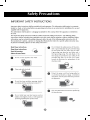
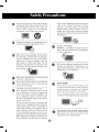
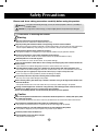
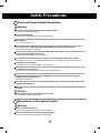
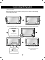
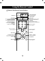
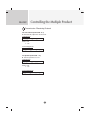
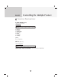
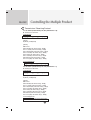
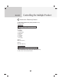
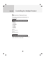
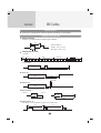
User’s Guide
M4212C
Make sure to read the Safety Precautions before using the product.
Keep the User's Guide(CD) in an accessible place for future reference.
See the label attached on the product and give the information to your dealer when you ask
for service.
Safety Precautions
Maintenance and Servicing
Never remove the back cover of the TV : this can expose you to
high voltage and other hazards. If the TV does not operate
properly, unplug it and call authorized service center or PDI.
Cleaning and Disinfection
Clean the exterior of this TV by removing dust with a lint-free cloth.
Caution : To avoid damage to the surface of the TV, do not use abrasive
or chemical cleaning agents.
Clean only with dry cloth.
Note to cable/TV Installer
This reminder is provided to call the CATV system installer's
attention to Article 820-40 of the National Electric Code.(U.S.A).
The code provides guidelines for proper grounding and, in
particular, specifies that the cable ground shall be connected to
the grounding system of the building, as close to the point of the
cable entry as practical.
1
Safety Precautions
2
Safety Precautions
3
Safety Precautions
Please read these safety precautions carefully before using the product.
Warning If you ignore the warning message, you may be seriously injured or there is a possibility of
accident or death.
Caution If you ignore the caution message, you may be slightly injured or the product may be damaged
Precautions in installing the Product
Warning
Keep away from heat sources like electrical heaters.
- Electrical shock, fire, malfunction or deformation may occur.
Keep the packing anti-moisture material or vinyl packing out of the reach of children.
- Anti-moisture material is harmful if swallowed. If swallowed by mistake, force the patient to vomit and visit the
nearest hospital. Additionally, vinyl packing can cause suffocation. Keep it out of the reach of children.
Do not put heavy objects on the product or sit upon it.
- If the product collapses or is dropped, you may be injured. Children must pay particular attention.
Do not leave the power or signal cable unattended on the pathway.
- The passerby can falter, which can cause electrical shock, fire, product breakdown or injury.
Install the product in a neat and dry place.
- Dust or moisture can cause electrical shock, fire or product damage.
If you can smell smoke or other odors or hear a strange sound unplug the power cord and contact the
service center.
- If you continue to use without taking proper measures, electrical shock or fire can occur.
If you dropped the product or the case is broken, turn off the product and unplug the power cord.
- If you continue to use without taking proper measures, electrical shock or fire can occur. Contact the service center.
Do not drop an object on or apply impact to the product. Do not throw any toys or objects on the product screen.
- It can cause injury to human, problem to product and damage the display.
Do not let the product fall or drop when connecting it with an external device.
- This may cause injury and/or damage to the product.
When connecting it with a game device, keep a distance of four times as long as the diagonal measurement of the
screen from the device.
- If the product falls because of the short cable, this may cause injury and/or damage to the product.
Leaving a fixed image on the screen for a long time may cause damage to the screen and cause
image burn-in. Make sure to use a screen saver on the product.
Burn-in and related problems are not covered by the warranty on this product.
Caution
Make sure the product ventilation hole is not blocked. Install the product in a suitably wide place (more
than 10cm from the wall)
- If you install the product too close to the wall, it may be deformed or fire can break out due to internal heat.
Do not block the ventilation hole of the product by a tablecloth or curtain.
- The product can be deformed or fire can break out due to overheating inside the product.
Install the product on a flat and stable place that has no risk of dropping the product.
- If the product is dropped, you may be injured or the product may be broken.
Install the product where no EMI occurs.
Keep the product away from direct sunlight.
- The product can be damaged.
4
Safety Precautions
Electrical Power Related Precautions
Warning
Make sure to connect the power cable to the grounded current.
- You may be electrocuted or injured.
Use the rated voltage only.
- The product can be damaged, or you may be electrocuted.
In the presence of thunder and lightning, never touch the power cord and signal cable because it can be
very dangerous.
- It can cause electric shock.
Do not connect several extension cords, electrical appliances or electrical heaters to a single outlet.
Use a power bar with a grounding terminal designed for exclusive use with the computer.
- A fire can break out due to overheating.
Do not touch the power plug with wet hands. Additionally, if the cord pin is wet or covered with dust, dry
the power plug completely or wipe dust off.
- You may be electrocuted due to excess moisture.
If you don’t intend to use the product for a long time, unplug the power cable from the product.
- Covering dust can cause a fire, or insulation deterioration can cause electric leakage, electric shock or fire.
Fix the power cable completely.
- If the power cable is not fixed completely, a fire can break out.
Hold the plug when pulling out the power cable. Do not bend the power cord with excessive force or put
heavy objects on the power cord.
- The power line can be damaged, which may cause electric shock or fire.
Do not insert a conductor (like a metal chopstick) into one end of the power cable while the other end is
connected to the input terminal on the wall. Additionally, do not touch the power cable right after
plugging into the wall input terminal.
- You may be electrocuted.
The power supply cord is used as the main disconnection device. Ensure that the socket-outlet is easily
accessible after installation.
Main power breaker is the power cord and this breaking device must be located at a location where it is easy
to operate.
Caution
Do not unplug the power cord while the product is in use.
- Electrical shock can damage the product.
Precautions in Moving the Product
Warning
Make sure to turn off the product.
- You may be electrocuted or the product can be damaged.
Make sure to remove all cables before moving the product.
- You may be electrocuted or the product can be damaged.
5
Safety Precautions
Caution
Do not shock the product when moving it.
- You may be electrocuted or the product can be damaged.
Do not dispose the product-packing box. Use it when you move.
Make the panel face forward and hold it with both hands to move.
- If you drop the product, the damaged product can cause electric shock or fire. Contact with the service center
for repair.
Precautions in Using the Product
Warning
Do not disassemble, repair or modify the product at your own discretion.
- Fire or electric shock accident can occur.
- Contact the service center for check, calibration or repair.
When the display is to be left unattended for an extended period of time, unplug it from the wall outlet.
Keep the product away from water.
- Fire or electric shock accident can occur.
Caution
Do not put or store inflammable substances near the product.
- There is a danger of explosion or fire due to careless handling of the inflammable substances.
When cleaning the brown tube surface, unplug the power cord and scrub with soft cloth to prevent
scratching. Do not clean with a wet cloth.
- The water can sink into the product, which can cause electric shock or serious malfunction.
Take a rest from time to time to protect your vision.
Keep the product clean at all times.
Take a comfortable and natural position when working with a product to relax the muscles.
Take a regular break when working with a product for a long time.
Do not press strongly upon the panel with a hand or sharp object such as nail, pencil or pen, or make
a scratch on it.
Keep the proper distance from the product.
- Your vision may be impaired if you look at the product too closely.
Set the appropriate resolution and clock by referring to the User’s Guide.
- Your vision can be impaired.
Use authorized detergent only when cleaning the product. (Do not use benzene, thinner or alcohol.)
- Product can be deformed.
On Disposal
The fluorescent lamp used in this product contains a small amount of mercury.
Do not dispose of this product with general household waste.
Disposal of this product must be carried out in accordance to the regulations of your local authority.
6
Connecting the Speakers
- Only on some models.
Mount the product onto the speaker by using a screw as shown in the following
connect the speaker cable.
After installing your speakers, use holders and cable ties to organize the speaker cables.
Cable holder
Remove the paper.
* This feature is not available in all model.
When the speaker is installed.
Cable tie
*Connect the input terminal with a
proper color match.
* This feature is not available in all model.
7
Using the Remote Control
Name of the Remote Control Buttons
• Power On/Off Button
• Input Select Button
(See next page)
• AV Button
• Sleep Button
When watching AV, RGB PC,HDMI/DVI
,Component1, Component2
The product will be automatically turned
off after a certain period of time.
Press this button repetitively to
select an appropriate time duration
• PSM Button
- Toggles through preset video
settings.
There is not a function
which is supported
1
2
3
4
5
6
7
8
9
• ARC button
Aspect Ratio Correction. Toggles
through aspect ratio options.
• Auto Button
Automatic adjustment function
(Operational for the analog signal only)
There is not a function
which is supported
0
There is not a function
which is supported
• Exit Button
• Menu Button
• Volume
Button
Volume up and down
• UP and Down buttons
Bring up and down direction
adjustment.
• Check Button
*
• Mute button
There is not a function
which is supported
8
Name and Function of the Parts
* The product image in the user’s guide could be different from the actual image.
Rear View
AV IN/OUT
Power Connector : Connect the power cord
RS-232C Serial Ports
RGB PC, HDMI/DVI Ports
-HDMI Supports High Definition input and HDCP (High-bandwidth Digital Content
Protection). Some devices require HDCP in order to display HD signals.
PC Sound Jack
: Connect the audio cable to the *LINE OUT jack of the PC sound card.
Wired Remote Control Port
AV Ports
Speaker Ports
*LINE OUT
A terminal used to connect to the speaker including a built-in amplifier (Amp). Make sure that
the connecting terminal of the PC sound card is checked before connecting. If the Audio Out of
PC sound card has only Speaker Out, reduce the PC volume.
If the Audio Out of the PC sound card supports both Speaker Out and Line Out, convert to Line Out using
the card jumper of the program (Refer to the Sound Card Manual).
9
Connecting to External Devices
When Connecting to your PC
First of all, see if the computer, product and the peripherals are turned off.
Then, connect the signal input cable.
A When connecting with the D-Sub signal input cable.
B When connecting with the HDMI to DVI signal input cable (not included).
A
PC
Rear side of the product.
PC/MAC
MAC
Macintosh Adapter (not included)
Use the standard Macintosh adapter since an incompatible
adapter is available in the market. (Different signaling system)
B
(not included)
Rear side of the product.
PC
* User must use shielded signal interface cables (D-sub 15 pin cable, DVI cable) with ferrite cores to maintain
standard compliance for the product.
Connect the Audio cable.
PC
Rear side of the product.
Connect the power cord.
Rear side of the product.
10
Connecting to External Devices
1 Turn on power by pressing the power button on the product.
SOURCE
AUTO/SET
ON/OFF
Power button
2 Turn on the PC.
Select an input signal.
Press the INPUT button on the remote control to select the input signal.
INPUT
SET
Or, press the SOURCE button on the back of the product.
SOURCE
AUTO/SET
A
When connecting with a D-Sub signal input cable.
• Select RGB PC : 15-pin D-Sub analog signal.
B
When connecting with a HDMI to DVI signal input cable.
• Select HDMI/DVI : HDMI to DVI Digital signal.
Note
Input
Input
AV
Component1
Component2
RGB PC
HDMI/DVI
AV
Component1
Component2
RGB PC
HDMI/DVI
• How to connect to two computers.
Connect the signal cables (HDMI to DVI and D-Sub) to each computer.
Press the INPUT button on the remote control to select the computer to use.
• Directly connect to a grounded power outlet or power strip (three prong connector.)
11
Connecting to External Devices
Daisy Chain Monitors
Use this function when displaying ANALOG RGB inputs of a PC to the other product.
• To use different products connected to each other
Connect one end of the signal input cable(15-pin D-Sub Signal Cable) to the RGB OUT
connector of product 1 and connect the other end to the RGB IN connector of other
products.
15-pin D-Sub Signal Cable
RGB IN
RGB IN
RGB IN
RGB IN
RGB OUT
RGB OUT
RGB OUT
RGB OUT
PC
PC
Product 1
Note
Product 2
Product 3
• When multi-connecting in/out cascade format, no loss cables are recommended.
We recommend that you should use cable distributor.
12
Product 4
Connecting to External Devices
VESA FDMI wall Mounting
This product supports a VESA FDMI compliant mounting interface. These mounts are purchaed
separately and not available from LG. Refer to the instructions included with Wall mount for more info.
The Set is equipped with a kensington Securify
System connector on the back panel. The cable and
lock are available separate and are not sold by LG.
For more info, visit http://www.kensington.com, the
internet home page of the Kensington company.
WARNING
GTo
prevent injury, this apparatus must be securely attached to the wall in accordance
with the installation instructions.
Optional Installer Remote Control for model No. Series M4212C
There is an optional Installer remote control available for the M4212C Models. The installer remote
control is NOT included with the TV.
Option Extras
Wall Mounting Bracket
(AP-WX60)
13
Connecting to External Devices
• AV Button
• Input Select Button
Toggles through video
If you press the button once,
the following Input Signal
Window will appear. Select
the signal type you want
using the
button.
AV
Component1
Component2
RGB PC
HDMI/DVI
1
2
Input
3
4
5
6
7
8
9
AV
Component1
Component2
RGB PC
HDMI/DVI
0
*
Inserting batteries into remote control.
1. Slide off the battery cover.
2. Insert the batteries with correct polarity (+/-).
3. Close the battery cover.
• Dispose of used batteries in the recycle bin to prevent
environmental pollution.
AAA Type
14
Connecting to External Devices
Video Input
Connect the video cable as shown in the below figure and then connect the power
cord (See page 10).
A When connecting with a BNC cable.
B When connecting with a S-Video cable.
• Connect to the S-Video input terminal to
watch high image quality movies.
• Connect the input terminal with a
proper color match.
Product
Product
IN
IN
OUT
OUT
Audio Cable
(not included)
Audio Cable
(not included)
BNC Cable
(not included)
S-Video Cable
(not included)
VCR/DVD Receiver
VCR/DVD Receiver
Select an input signal.
Press the INPUT button on the remote control to select the input signal.
INPUT
SET
Or, press the SOURCE button on the back of the product.
SOURCE
AUTO/SET
A
When connecting with an BNC cable.
• Select AV.
B
When connecting with an S-Video cable.
Input
AV
Component1
Component2
RGB PC
HDMI/DVI
• Select AV.
Note
• When the BNC cable is connected simultaneously with S-Video cable, S-Video input has a priority.
15
Connecting to External Devices
Component Input (480i/480p/576i/576p/720p/1080i)
Connect the video/audio cable as shown in the below figure and then, connect the
power cord (See page 10).
• Connect the input terminal with a proper color match.
Product
A
Product
M
BNC Cable
(not included)
B
Audio Cable
(not included)
M
BNC Cable
(not included)
HDTV Receiver
Audio Cable
(not included)
HDTV Receiver
Note
- Some devices may require HDCP in order to display HD signals.
- Component doesn't support HDCP.
Select an input signal.
Press the INPUT button on the remote control to select the input signal.
INPUT
SET
Or, press the SOURCE button on the back of the product.
SOURCE
A
• Select Component 1
B
• Select Component 2
AUTO/SET
16
Input
Input
AV
Component1
Component2
RGB PC
HDMI/DVI
AV
Component1
Component2
RGB PC
HDMI/DVI
Connecting to External Devices
HDMI Input (480p/576p/720p/1080i/1080p)
-HDMI Supports High Definition input and HDCP (High-bandwidth Digital Content
Protection). Some devices require HDCP in order to display HD signals.
Connect the video/audio cable as shown in the below figure and then connect the
power cord (See page 10).
Product
Product
HDMI to DVI
Signal Cable
(not included)
RCA-PC
Audio Cable
VCR/DVD/Set-top Box
HDMI Signal Cable
(not included)
VCR/DVD/Set-top Box
Note : Dolby Digital is not supported.
Select an input signal.
Press the INPUT button on the remote control to select the input signal.
INPUT
SET
Or, press the SOURCE button on the back of the product.
SOURCE
AUTO/SET
Input
When connecting with a HDMI to DVI signal input cable.
When connecting with a HDMI signal input cable.
• Select HDMI/DVI
17
AV
Component1
Component2
RGB PC
HDMI/DVI
Connecting to External Devices
Watching AV Outputs
- When using AV input, you can connect the AV Out to other monitors.
Video/TV
BNC Cable
(not included)
Audio Cable
(not included)
IN
Product
OUT
BNC Cable
(not included)
Audio Cable
(not included)
Video/TV
Note
• When multi-connecting in/out cascade format, no loss cables are recommended.
We recommend that you should use cable distributor.
18
User Menus
Screen Adjustment options
SOURCE
SOURCE
Power Button
AUTO/SET
ON/OFF
AUTO/SET
ON/OFF
• Press this button to turn on the power. Press this button again to
turn it off.
Power Indicator
• This Indicator lights up blue when the display operates normally(on
mode). If the display is in sleep (Energy Saving) mode, this indicator
color changes to amber.
MENU Button
• Use this button to show/hide the OSD (On Screen Display) menu
screen.
OSD Select /
Adjust Button
• Use this button to select an icon or adjust the setting in the OSD screen.
• Adjust the up and down.
• Adjust the volume.
19
Volume
35
User Menus
Screen Adjustment options
AUTO/SET Button
[For PC Analog signal]
[When XGA Mode is active and
1360 X768 is selected]
SOURCE Button
IR Receiver
SOURCE
AUTO/SET
- Toggles between inputs
Input
AV
Component 1
Component 2
RGB PC
HDMI/DVI
AV
Component1
Component2
RGB PC
HDMI/DVI
Composite Video, Separate Video
HDTV, DVD
HDTV, DVD
15-pin D-Sub analog signal
Digital signal
• This is where the unit receives signals from the remote control.
20
User Menus
OSD Menu
Icon
Function Description
Adjusts screen brightness, contrast and color that you prefer.
Picture
Adjusts the audio options.
Audio
Adjusts the timer options.
Time
Adjusts the screen status according to the circumstances.
Option
Adjust Set ID and check Serial No. and SW version.
Information
Note
OSD(On Screen Display)
The OSD function enables you to adjust the screen status conveniently since it provides
graphical presentation.
21
User Menus
How to adjust the OSD (On Screen Display) screen
Pops up
the menu
screen
Move where
you want to
adjust
Select a
menu icon
Move where
you want to
adjust
Select a
menu icon
Adjust the status
Save
adjustment
Exit from the
menu screen.
• Use the remote control to adjust the OSD screen.
1
Press the MENU Button, then the main menu of the OSD appears.
2
To access a control, use the
3
When the icon you want becomes highlighted, press the SET Button.
4
Use the
5
Accept the changes by pressing the SET Button.
6
Exit the OSD by pressing the EXIT Button.
Buttons.
Buttons to adjust the item to the desired level.
How to adjust the screen automatically
Press the AUTO/SET button (AUTO button on a remote Control) in the
PC analog signal. Then optimal screen settings will be selected that fit
into the current mode. If adjustment is not satisfactory, you can adjust
the screen manually.
22
[When XGA Mode is active and
1360 X768 is selected]
User Menus
Adjusting Screen Color
Picture
Mode
Picture
Picture Mode
Color Temperature
Advanced
Aspect Ratio
Picture Reset
Screen
Vivid
Standard
Cinema
Sport
Game
User1
User2
MENU
Toggles between screen presets.
• Vivid : Select this option to display with a sharp image.
• Standard : The most general and natural screen display status.
• Cinema : Select this option to lower brightness by one level.
• Sport : Select this option to display with a soft image.
• Game : To enjoy dynamic image when playing a game.
• User1,2 : Select this option to use the user-defined settings.
User2
Backlight
Contrast
Brightness
Color
Sharpness
Tint
Expert
20
90
50
50
50
50
MENU
Backlight : To control the brightness of the screen,adjust the brightness of LCD panel.
Contrast : Adjust the difference between the light and dark levels in the picture.
Brightness : To adjust the brightness of the screen.
Color : To adjust the color to desired level.
Sharpness : To adjust the clearness of the screen.
Tint :To adjust the tint to desired level.
Expert : To compensate for each image mode, or adjust image values according to a
particular image. (Applied only to User2 menu.)
Note
If the 'Picture Mode' setting in the Picturemenu is set to Vivid, Standard, Cinema,
Sport or Game the subsequent menus will be automatically set.
23
User Menus
Adjusting Screen Color
Color
Temperature
Picture
Picture Mode
Color Temperature
Advanced
Aspect Ratio
Picture Reset
Screen
Cool
Medium
Warm
User
MENU
Color Settings
• Cool : Slightly purplish white.
• Medium : Slightly bluish white.
• Warm : Slightly reddish white.
• User : Select this option to use the user-defined settings.
User
Red
Green
Blue
0
0
0
MENU
Red / Green / Blue
Set your own color levels.
24
User Menus
Adjusting Screen Color
Advanced
Picture
Picture Mode
Color Temperature
Advanced
Aspect Ratio
Picture Reset
Screen
To set
MENU
• Gamma : Set your own gamma value. : -50/0/50
On the monitor, high gamma values display whitish images and low gamma
values display high contrast images.
• Film Mode : (Function works in the following mode - AV, Component 480i/576i)
When you watch a movie, this function adjusts the set to the best picture
appearance.
• Black Level : (Function works in the following mode - AV(NTSC), HDMI/DVI
adjusts the contrast and the brightness of the screen using the
black level of the screen.
• Low : The reflection of the screen gets brighter.
• High : The reflection of the screen gets darker.
• NR : Removing the noise up to the point where it does not damage the
original picture.
25
User Menus
Adjusting Screen Color
Aspect Ratio To select the image size of the screen.
Picture
Picture Mode
Color Temperature
Advanced
Aspect Ratio
Picture Reset
Screen
16:9
Original
4:3
14:9
Zoom1
Zoom2
MENU
<AV>
16:9
Widescreen mode.
Just Scan
Allows you to enjoy the transmitted data fully without any images cut off.
(* This menu is activated only in 720p, 1080p and 1080i in Component mode.)
Original
The aspect ratio is not adjusted from the original. It is set by the program
being watched.
4:3
This picture format is 4:3 aspect ratio.
1:1
The aspect ratio is not adjusted from the original. Used in PC mode.
(Only HDMI/ DVI PC, RGB PC)
14:9
14:9 programs are viewed normally in 14:9 with black bars added to the
top and bottom. 4:3 programs are magnified on the top/bottom and
left/right sides.
Zoom1, 2
4:3 programes are magnified until they fill the 16:9 screen. The top and
bottom will be cut off.
ARC
MODE
DTV
16:9
Just Scan
Original
4:3
1:1
14:9
Zoom1
Zoom2
26
PC
PC
User Menus
Adjusting Screen Color
Picture Reset Return Picture Mode, Color Temperature, Advanced to the default factory
settings.
Picture
Picture Mode
Color Temperature
Advanced
Aspect Ratio
Picture Reset
Screen
To set
MENU
Screen
Adjust the screen video.
Picture
Picture Mode
Color Temperature
Advanced
Aspect Ratio
Picture Reset
Screen
Screen
To set
Auto Config.
Manual Config.
XGA Mode
Reset
To set
MENU
MENU
Auto Config. (RGB PC input only) : This button is for the automatic adjustment of the
screen position, clock and phase. This function is available for analog signals only.
Manual Config. : If the picture isn't clear after auto adjustment and characters are still
trembling, adjust the picture phase manually.
* Phase, Clock function are not available in Component, HDMI/DVI DTV.)
Clock : To minimize any vertical bars or stripes visible on the screen background. The
horizontal screen size will also change. This function is available for analog signals only.
Phase : To adjust the focus of the display. This item allows you to remove any horizontal
noise and clear or sharpen the image of characters. This function is available for analog
signals only.
H-Position : Moving the screen position horizontally.
V-Position : Moving the screen position vertically.
H-Size : Adjust the horizontal size of the screen.
V-Size : Adjust the vertical size of the screen.
XGA Mode (RGB-PC only). : For more improved or better picture quality, select the same
mode corresponding to computer resolution.
Reset: Return Manual config. to the default factory settings.
27
User Menus
Adjusting the audio function
Sound
Mode
The best sound tone quality will be selected automatically depending on the video type that you're currently watching.
Audio
Sound Mode
Auto Volume
Balance
Speaker
Clear Voice
Standard
Music
Cinema
Sport
Game
User
MENU
• Clear Voice : By differentiating the human sound range from others,it helps users listen to human
voices better.
• Standard : The most commanding and natural audio.
• Music : Select this option to enjoy the original sound when listening to the music.
• Cinema : Select this option to enjoy sublime sound.
• Sport : Select this option to watch sports broadcasting.
• Game : To enjoy dynamic sound when playing a game.
• User : Select this option to use the user-defined audio settings.
User
0.1
0.5
1.5
5.0
10
KHz
MENU
Auto
Volume
To adjust uneven sound volumes across all channels or signals automatically to the most
appropriate level. To use this feature, select On.
Balance Use this function to balance sound from the left and right speakers.
Speaker You can adjust internal speaker status.
If you want to use your external hi-fi stereo system, turn off the internal speakers of the set.
Note
When connected to your computer and the 'Sound
Mode' setting in the audio menu is Clear Voice, Standard, Music, Cinema or Sport, the
available menus are Balance, Auto Volume, Speaker.
28
User Menus
Adjusting the timer function
Time
_ _ : _ _ AM
Clock
On/Off Timer
Sleep Time
Auto Sleep
Power On Delay
MENU
Clock
If the current time is incorrect, reset the clock manually.
button to select the Time menu.
1) Press the MENU button and then use
2) Press the
button and then use
button to select the Clock menu.
3) Press the
button and then use
button to set the hour(00~23).
4) Press the
button and then use
button to set the minutes(00~59).
On/Off Timer The off time automatically switches the set to standby at the pre-set time.
1) Press the MENU button and then use
2) Press the
button and then use
3) Press the
button and then use
4) Press the
button and then use
5) Press the
button and then use
button to select the Time menu.
button to select On/Off Timer.
button to set the hour(00~23).
button to set the minutes(00~59).
button to select On or Off.
Sleep Time
The power is automatically turned off when the time set by a user is passed.
1) Press the MENU button and then use
button to select the Sleep Time menu.
2) Press the
button and then use
button to set the hour(00~23).
3) Press the
button and then use
button to set the minutes(00~59).
Auto Sleep
If Auto Sleep is active and there is no input signal, the set switches to off mode
automatically after 10 minutes.
button to select the Auto Sleep menu.
1) Press the MENU button and then use
2) Press the
button and then use
button to select On or Off.
Power On
Delay
When connecting multiple monitors and turning the power on, the monitors are
turned on individually to prevent overload.
Note
In the event of power interruption (disconnection or power failure), the clock must be reset.
Once the on or off time is set, these functions operate daily at the preset time.
Off time function overrides On time function if they are set to the same time.
When On time is operated, input screen is turned on as it was turned off.
29
User Menus
Selecting the options
Option
Language
Key Lock
ISM Method
Power Indicator
Logo Light
DPM Select
Tile Mode
Factory Reset
To set
MENU
Language
To choose the language in which the control names are displayed.
Key Lock
Use the
buttons to select On or Off. The monitor can be set up so that it can only be
used with the remote control. This feature can prevent unauthorized viewing.
In order to lock the OSD screen adjustment, set the Key Lock tab to the 'On' position.
In order to unlock it, do the following :
• Push the MENU button on the remote control and set Key Lock to the 'Off' position.
ISM Method
A frozen or still picture from a PC/Video game displayed on the screen for prolonged periods could
result in a ghost image remaining even when you change the image. Avoid allowing a fixed image to
remain on the screen for a long period of time.
Normal : Leave on normal if you don't foresee image burn in being a problem.
White wash : White wash fills the screen with solid white. This helps removes permanent
images burned into the screen. A permanent image may be impossible to clear entirely
with white wash.
Orbiter : May help prevent ghost images. However, it is best not to allow any fixed image to
remain on the screen. To avoid a permanent image on the screen, the screen will move every 2
minutes.
Inversion : This function inverts the panel color of the screen. The panel color is
automatically inverted every 30 minutes.
Dot Wash : This function moves the black dots of the screen. The black dots is automatically
moved every 5 second.
Power Indicator Use this function to set the power indicator on the front side of the product to
On or Off.
Logo Light
Use this function to set the Logo Light on the front side of the product to On or
Off.
DPM Select
A user can choose to turn the power saving mode on / off.
30
User Menus
Selecting the options
• To use this function
- Must be displayed with various other products.
- Must be in a function that can be connected to RS-232C or RGB Out
Option
Tile mode
Language
Key Lock
ISM Method
Power Indicator
Logo Light
DPM Select
Tile Mode
Factory Reset
Tile Mode
H-Size
V-Size
H-Position
V-Position
Reset
Tile ID
Natural
Off
0
0
<>
<>
It is used to enlarge the screen and
also used with several products to
view screen.
1
Off
MENU
• Tile Mode
Tile mode and choose Tile alignment and set the ID of the current product to set
location.
* Only after pressing the SET button the
adjustments made to the settings will be saved.
- Tile mode : row x column ( r = 1, 2, 3, 4,5 c = 1, 2, 3, 4,5)
- 5 x 5 available.
- Configuration of an integration screen is also available as well as
configuration of One by one Display.
- Tile mode (product 1 ~ 4) : r(2) x c(2)
row
ID 1
ID 2
column
ID 3
ID 4
31
User Menus
Selecting the options
- Tile mode (product 1 ~ 9) : r(3) x c(3)
row
ID 1
ID 2
ID 3
ID 4
ID 5
ID 6
ID 7
ID 8
ID 9
column
- Tile mode (product 1 ~ 2) : r(2) x c(1)
row
ID 2
ID 1
column
- Tile mode (product 1 ~16) : r(4) x c(4)
row
ID 1
ID 2
ID 3
ID 4
ID 5
ID 6
ID 7
ID 8
column
ID 9
ID10
ID 11
ID 12
ID 13
ID 14
ID 15
ID 16
32
User Menus
Selecting the options
Option
Tile mode
Language
Key Lock
ISM Method
Power Indicator
Logo Light
DPM Select
Tile Mode
Factory Reset
Tile Mode
H-Size
V-Size
H-Position
V-Position
Reset
Tile ID
Natural
Off
0
0
<>
<>
1
Off
MENU
Factory Reset
• H-Size
Adjust the horizontal size of the screen taking into account the size of the
bezel.
• V-Size
Adjust the vertical size of the screen taking into account the size of the bezel.
• H-Position
Moving the screen position horizontally.
• V-Position
Moving the screen position vertically.
• Reset
Function to initialize and release Tile.
All Tile setting are released when selecting Tile recall and the screen returns
to Full screen.
• Tile ID
Select the location of the Tile by setting an ID.
• Natural
The image is omitted by the distance between the screens to be naturally shown.
Select this option to return to the default factory settings.
33
User Menus
Adjust Set ID and check Serial No. and SW version.
Information
Set ID
Serial No.
SW Version
MENU
Set ID
You can assign a unique Set ID NO (name assignment) to each product when several
products are connected for display. Specify the number (1~99) using the
button
and exit. Use the assigned Set ID to individually control each product using the Product
Control Program.
Serial No.
This menu shows the serial number of the product.
SW Version
This menu shows the software version.
34
Troubleshooting
No image is displayed
● Is the product power cord connected?
• See if the power cord is properly connected to the
outlet.
● Is the power indicator light on?
• See if the power switch is turned on.
• May need service.
● Power is on, power indicator is blue but • Adjust brightness and contrast again.
the screen appears extremely dark.
• Backlight may need repair.
● the power indicator amber?
• If the product is in power saving mode, move the
mouse or press any key.
• Turn both devices off and then back on.
● Does the 'Out of range' message
appear?
• The signal from the PC (video card) is out of the
vertical or horizontal frequency range of the
product. Adjust the frequency range by referring
to the Specifications in this manual.
* Maximum resolution
RGB : 1600 x 1200 @60Hz
HDMI/DVI : 1920 x 1080 @60Hz
● Does the 'Check signal cable' message • The signal cable between PC and product is not
appear?
connected. Check the signal cable.
• Press the 'INPUT' menu in the remote Control to
check the input signal.
'Unknown Product' message appears when the product is connected.
● Did you install the driver?
• Install the product driver, which is provided with
the product, or download it from the web site.
(http://www.lge.com)
• See if the plug&play function is supported by
referring to the video card user manual.
'Key Lock On' message appears.
Note
• The control locking function prevents unintentional
OSD setting change due to careless usage. To unlock
the controls, simultaneously press the Menu button
and button for several seconds. (You cannot set this
function using the remote control buttons. You can set
this function in the product only.)
▲
● The 'Key Lock On' message
appears when pressing the Menu
button.
* Vertical frequency: To enable the user to watch the product display, screen image should be changed tens of times
every second like a fluorescent lamp. The vertical frequency or refresh rate is the times of image display per second.
The unit is Hz.
* Horizontal frequency: The horizontal interval is the time to display one vertical line. When 1 is divided by the
horizontal interval, the number of horizontal lines displayed every second can be tabulated as the horizontal
frequency. The unit is kHz.
35
Troubleshooting
The screen image looks abnormal.
● Is the screen position wrong?
• D-Sub analog signal – Press the “AUTO” button in
the remote control to automatically select the
optimal screen status that fits into the current
mode. If adjustment is not satisfactory, use the
Position OSD menu.
• See if the video card resolution and frequency are
supported by the product. If the frequency is out of
range, set to the recommended resolution in the
Control Panel – Display – Setting menu.
● Do thin lines appear on the
background screen?
• D-Sub analog signal – Press the “AUTO” button
in the remote control to automatically select an
optimal screen status that fits into the current
mode. If adjustment is not satisfactory, use the
Clock OSD menu.
● Horizontal noise appears or the
characters look blurred.
• D-Sub analog signal – Press the “AUTO” button
in the remote control to automatically select an
optimal screen status that fits into the current
mode. If adjustment is not satisfactory, use the
Phase OSD menu.
● The screen is displayed abnormally.
• The proper input signal is not connected to the
signal port. Connect the signal cable that matches
with the source input signal.
After-image appears on the product.
● After-image appears when the
product is turned off.
• If you use a fixed image for a long time, the pixels
may be damaged quickly. Use the screen-saver
function.
36
Troubleshooting
The audio function does not work.
● No sound?
• See if the audio cable is connected properly.
• Adjust the volume.
• See if the sound is set properly.
• Select the appropriate equalize sound.
● Sound is too dull.
• Adjust the volume.
● Sound is too low.
Screen color is abnormal.
● Screen has poor color resolution
(16 colors).
• Set the number of colors to more than 24 bits (true
color)
Select Control Panel – Display – Settings – Color
Table menu in Windows.
● Screen color is unstable or monocolored.
• Check the connection status of the signal cable.
Or, re-insert the PC video card.
● Do black spots appear on the screen?
• Several pixels (red, green, white or black color)
may appear on the screen, which can be
attributable to the unique characteristics of the
LCD panel. It is not a malfunction of the LCD.
37
Specifications
The product specifications can change without prior notice for product improvement.
LCD Panel
Power
Dimensions
&Weight
42 inches Visible diagonal (106.72 cm) TFT (Thin Film Transistor)
LCD (Liquid Crystal Display) Panel
0.681 mm X 0.681 mm (Pixel Pitch)
Rated Voltage
Power Consumption
AC 100-240V~ 50/60Hz 2.2A
On Mode
: 220W Typ.
Sleep Mode
: ≤ 1W (RGB) / 4W(HDMI/DVI)
Off Mode
: ≤ 1W
[1]
[2]
H
H
W
W
D
D
Width x Height x Depth
[1] 99.56 cm (39.19 inches) x 58.76 cm (23.13 inches) x 11.37 cm (4.47 inches)
[2] 99.56 cm (39.19 inches) x 58.76 cm (23.13 inches) x 11.37 cm (4.47 inches)
Net
[1] 21.1 kg (46.54 lbs)
[2] 23.7 kg (52.25 lbs)
NOTE
Information in this document is subject to change without notice.
38
Specifications
The product specifications can change without prior notice for product improvement.
Video Signal
Max. Resolution
RGB : 1600 X 1200 @60Hz
HDMI/DVI : 1920 X 1080 @60Hz – It may not be supported
depending on the OS or video card type.
Recommended Resolution RGB : WSXGA 1360 X 768 @60Hz
HDMI/DVI : WSXGA 1360 X 768 @60Hz – It may not be
supported depending on the OS or video card type.
Horizontal Frequency
RGB : 30 - 83 kHz
HDMI/DVI : 30 - 83 kHz
Vertical Frequency
RGB : 56 - 75 Hz
HDMI/DVI : 56 - 60 Hz
Synchronization Type Separate/Composite/Digital
15-pin D-Sub type, HDMI (digital), S-Video,
Composite Video, Component, RS-232C
Input Connector
Environmental
Conditions
Operational Condition Temperature: 0˚C ~ 40˚C , Humidity: 10% ~ 80%
Storage Condition
Temperature: -20˚C ~ 60˚C , Humidity: 5% ~ 90%
* Applicable only for models that support the speakers
Audio
RMS Audio Output
Input Sensitivity
Speaker Impedance
10W+10W(R+L)
0.7Vrms
8Ω
NOTE
Information in this document is subject to change without notice.
39
Specifications
PC Mode – Preset Mode
Preset mode
Horizontal
Frequency
(kHz)
Vertical
Frequency
(Hz)
640 x 350
720 x 400
640 x 480
640 x 480
800 x 600
800 x 600
832 x 624
1024 x 768
1024 x 768
1280 x 720
31.469
31.468
31.469
37.5
37.879
46.875
49.725
48.363
60.123
44.772
70.8
70.8
59.94
75
60.317
75
74.55
60
75.029
59.855
1
2
*3
4
*5
6
7
*8
9
*10
Preset mode
*11
*12
*13
*14
15
16
*17
1280 x 768
1360 x 768
1366 x 768
1280 x 1024
1280 x 1024
1600 x 1200
1920 x 1080
480i
576i
480p
576p
720p
1080i
1080p
HDMI/DVI(DTV)
o
o
o
o
o
o
X
x
x
o
o
o
o
o
Power Indicator
Mode
On Mode
Sleep Mode
Off Mode
47.7
47.72
47.7
63.981
79.98
75.00
67.5
60
59.799
60
60.02
75.02
60
60
1~16 : RGB mode
* : HDMI/DVI mode
DTV Mode
Component
Horizontal Vertical
Frequency Frequency
(Hz)
(kHz)
Product
Blue
Amber
-
NOTE
DTV/PC selection on HDMI/DVI inputs is available for PC resolutions :
640 X 480/60Hz, 1280 X 720/60Hz and DTV resolutions : 480p, 720p.
40
RS-232C
Controlling the Multiple Product
Use this method to connect several products to a single PC.
You can control several products at a time by connecting them to a single PC.
Connecting the cable
Connect the RS-232C cable as shown in the picture.
* The RS-232C protocol is used for communication between the PC and product. You can
turn the product on/off, select an input source or adjust the OSD menu from your PC.
RS-232C Cable
(not included)
PC
monitor 1
monitor 3
monitor 2
monitor 4
RS-232C Configurations
3-Wire Configurations (Not Standard)
7-Wire Configurations (Standard RS-232C cable)
PC
RXD
TXD
GND
DTR
DSR
RTS
CTS
2
3
5
4
6
7
8
D-Sub 9
(Female)
PC
Monitor
3
2
5
6
4
8
7
RXD
TXD
GND
DTR
DSR
RTS
CTS
TXD
RXD
GND
DSR
DTR
CTS
RTS
2
3
5
4
6
7
8
D-Sub 9
(Female)
D-Sub 9
(Female)
Communication Parameter
▲▲ ▲ ▲ ▲▲▲
Baud Rate : 9600buadRate (UART)
Data Length : 8bits
Parity Bit : None
Stop Bit : 1bit
Flow Control : None
Communication Code : ASCII code
Use a crossed (reverse) cable
A1
Monitor
3
2
5
6
4
7
8
D-Sub 9
(Female)
TXD
RXD
GND
DTR
DSR
RTS
CTS
RS-232C
Controlling the Multiple Product
Command Reference List
01. Power
02. Input Select
03. Aspect Ratio
04. Screen Mute
05. Volume Mute
06. Volume Control
07. Contrast
08. Brightness
09. Color
10. Tint
11. Sharpness
12. OSD Select
13. Remote Lock/ key Lock
14. Balance
15. Color Temperature
16. Abnomal state
17. ISM mode
18. Auto configuration
19. Key
20. Tile Mode
21. Tile H Size
22. Tile V Size
23. Tile ID Set
24. Natural Mode (In Tilemode)
25. Elapsed time return
26. Temperature value
27. Lamp fault check
28. Auto Volume
29. Speaker
30. Time
31. On Timer (On/Off Timer) On, Off
32. Off Timer (On/Off Timer) On, Off
33. On Timer (On/Off Timer) Time
34. Off Timer (On/Off Timer) Time
35. Sleep Time
36. Auto Sleep
37. Power On Delay
38. Language
39. DPM Select
40. Reset
41. S/W Version
42. Input Select
COMMAND1
k
k
k
k
k
k
k
k
k
k
k
k
k
k
k
k
j
j
m
d
d
d
d
d
d
d
d
d
d
f
f
f
f
f
f
f
f
f
f
f
f
x
COMMAND2
a
b
c
d
e
f
g
h
i
j
k
l
m
t
u
z
p
u
c
d
g
h
i
j
l
n
p
u
v
a
b
c
d
e
f
g
h
i
j
k
z
b
A2
DATA1
00H - 01H
02H - 09H
01H - 09H
00H - 01H
00H - 01H
00H - 64H
00H - 64H
00H - 64H
00H - 64H
00H - 64H
00H - 64H
00H - 01H
00H - 01H
00H - 64H
00H - 03H
FFH
00H - 10H
01H
Key Code
00H - 55H
00H - 64H
00H - 64H
00H - 19H
00H - 01H
FFH
FFH
FFH
00H - 01H
00H - 01H
00H - 06H
00H, FFH
00H, FFH
00H - 07H
00H - 07H
00H - 08H
00H - 01H
00H - 64H
00H - 09H
00H - 01H
00H - 02H
FFH
20H - A0H
DATA2
DATA3
00H
00H
00H
00H
00H
00 - 3BH
- 17H
- FFH
- FFH
- 17H
- 17H
00 - 3BH
00 - 3BH
RS-232C
Controlling the Multiple Product
Transmission / Receiving Protocol
Transmission
[Command1][Command2][ ][Set ID][ ][Data][Cr]
* [Command 1]: First command. (k)
* [Command 2]: Second command.(a ~ u)
* [Set ID]: Set up the Set ID number of product.
range : 1~99. by setting '0', server can control all products.
* In case of operating with more than 2 sets using set ID as '0' at the same
time, it should not be checked the ack message.
Because all sets will send the ack message, so it's impossible the check the
whole ack messages.
* [DATA]: To transmit command data.
Transmit 'FF' data to read status of command.
* [Cr]: Carriage Return
ASCII code ‘0x0D’
* [ ]: ASCII code Space (0x20)’
OK Acknowledgement
[Command2][ ][Set ID][ ][OK][Data][x]
* The Product transmits ACK (acknowledgement) based on
this format when receiving normal data. At this time, if the
data is data read mode, it indicates present status data.
If the data is data write mode, it returns the data of the PC
computer.
Error Acknowledgement
[Command2][ ][Set ID][ ][NG][Data][x]
* If there is error, it returns NG
A3
Controlling the Multiple Product
RS-232C
Transmission / Receiving Protocol
▲
01. Power(Command : a)
To control Power On/Off of the Set.
Transmission
[k][a][ ][Set ID][ ][Data][Cr]
Data 0 : Power Off
1 : Power On
Acknowledgement
[a][ ][Set ID][ ][OK][Data][x]
▲
To show the status of Power On/Off.
Transmission
[k][a][ ][Set ID][ ][FF][Cr]
Acknowledgement
[a][ ][Set ID][ ][OK][Data][x]
Data 0 : Power Off
1 : Power On
▲
02. Input Select (Command : b) (Main Picture Input)
To select input source for the Set.
You can also select an input source using the INPUT
button on the remote control.
Transmission
[k][b][ ][Set ID][ ][Data][Cr]
Data 2 : AV
4 : Component 1
5 : Component 2
7 : RGB (PC)
8 : HDMI (DTV)
9 : HDMI (PC)
Acknowledgement
[b][ ][Set ID][ ][OK][Data][x]
Data 2 : AV
4 : Component 1
5 : Component 2
7 : RGB (PC)
8 : HDMI (DTV)
9 : HDMI (PC)
A4
RS-232C
Controlling the Multiple Product
Transmission / Receiving Protocol
▲
03. Aspect Ratio(Command : c) (Main picture format)
To adjust the screen format.
You can also adjust the screen format using the ARC
(Aspect Ratio Control) button on remote control or in the
Screen menu.
Transmission
[k][c][ ][Set ID][ ][Data][Cr]
Data 1 : Normal Screen (4:3)
2 : Wide Screen (16 :9)
4 : Zoom1
5 : Zoom2
6 : Original
7 :14:9
9 : Just Scan(HD DTV), 1:1 (RGB PC, HDMI/DVI PC)
Acknowledgement
[c][ ][Set ID][ ][OK][Data][x]
▲
04. Screen Mute(Command : d)
To select screen mute on/off.
Transmission
[k][d][ ][Set ID][ ][Data][Cr]
Data 0 : Screen mute off (Picture on)
1 : Screen mute on (Picture off)
Acknowledgement
[d][ ][Set ID][ ][OK][Data][x]
A5
RS-232C
Controlling the Multiple Product
Transmission / Receiving Protocol
▲
05. Volume Mute(Command : e)
To control On/Off of the Volume Mute.
Transmission
[k][e][ ][Set ID][ ][Data][Cr]
Data 0 : Volume Mute On (Volume Off)
1 : Volume Mute Off (Volume On)
Acknowledgement
[e][ ][Set ID][ ][OK][Data][x]
Data 0 : Volume Mute On (Volume Off)
1 : Volume Mute Off (Volume On)
▲
06. Volume Control(Command : f)
To adjust Volume .
Transmission
[k][f][ ][Set ID][ ][Data][Cr]
Data
Min : 00H ~ Max : 64H
(Hexadecimal code)
Acknowledgement
[f][ ][Set ID][ ][OK][Data][x]
Data
Min : 00H ~ Max : 64H
• Refer to ‘Real data mapping’ page A7.
A6
RS-232C
Controlling the Multiple Product
Transmission / Receiving Protocol
▲
07. Contrast(Command : g)
To adjust screen contrast.
You can also adjust the contrast in the Picture menu.
Transmission
[k][g][ ][Set ID][ ][Data][Cr]
Data
Min : 00H ~ Max : 64H
• Refer to ‘Real data mapping’ as shown below.
Acknowledgement
[g][ ][Set ID][ ][OK][Data][x]
* Real data mapping
0 : Step 0
:
A : Step 10
:
F : Step 15
10 : Step 16
:
64 : Step 100
▲
08. Brightness(Command : h)
To adjust screen brightness.
You can also adjust the brightness in the Picture menu.
Transmission
[k][h][ ][Set ID][ ][Data][Cr]
Data
Min : 00H ~ Max : 64H
• Refer to ‘Real data mapping’ as shown below.
Acknowledgement
[h][ ][Set ID][ ][OK][Data][x]
* Real data mapping
0 : Step
:
A : Step 10
:
F : Step 15
10 : Step 16
:
64 : Step 100
A7
RS-232C
Controlling the Multiple Product
Transmission / Receiving Protocol
▲
09. Color(Command : i) (Video only)
To adjust the screen color.
You can also adjust the color in the Picture menu.
Transmission
[k][i][ ][Set ID][ ][Data][Cr]
Data
Min : 00H ~ Max : 64H
(Hexadecimal code)
• Refer to ‘Real data mapping’ page A7.
Acknowledgement
[i][ ][Set ID][ ][OK][Data][x]
Data
Min : 00H ~ Max : 64H
▲
10. Tint(Command : j) (Video only)
To adjust the screen tint.
You can also adjust the tint in the Picture menu.
Transmission
[k][j][ ][Set ID][ ][Data][Cr]
Data
Red: 00H ~ Green: 64H
(Hexadecimal code)
• Refer to ‘Real data mapping’ page A7.
Acknowledgement
[j][ ][Set ID][ ][OK][Data][x]
Data
Red: 00H ~ Green: 64H
* Tint Real data mapping
0 : Step -50
:
64 : Step 50
A8
Controlling the Multiple Product
RS-232C
Transmission / Receiving Protocol
▲
11. Sharpness(Command : k) (Video only)
To adjust the screen Sharpness.
You can also adjust the sharpness in the Picture menu.
Transmission
[k][k][ ][Set ID][ ][Data][Cr]
Data
Min : 00H ~ Max : 64H
(Hexadecimal code)
• Refer to ‘Real data mapping’ page A7.
Acknowledgement
[k][ ][Set ID][ ][OK][Data][x]
Data
Min : 00H ~ Max : 64H
▲
12. OSD Select(Command : l)
To control OSD on/off to the set.
Transmission
[k][l][ ][Set ID][ ][Data][Cr]
Data 0 : OSD Off
1 : OSD On
Acknowledgement
[l][ ][Set ID][ ][OK][Data][x]
Data 0 : OSD Off
1 : OSD On
▲
13. Remote Lock /Key Lock (Command : m)
To control Remote Lock on/off to the set.
This function, when controlling RS-232C, locks the remote control and the local keys.
Transmission
[k][m][ ][Set ID][ ][Data][Cr]
Data 0 : Off
1 : On
Acknowledgement
[m][ ][Set ID][ ][OK][Data][x]
Data 0 : Off
1 : On
A9
RS-232C
Controlling the Multiple Product
Transmission / Receiving Protocol
▲
14 Balance(Command : t)
To adjust the sound balance.
Transmission
[k][t][ ][Set ID][ ][Data][Cr]
Data
Min : 00H ~ Max : 64H
(Hexadecimal code)
• Refer to ‘Real data mapping’ page A7.
Acknowledgement
[t][ ][Set ID][ ][OK][Data][x]
Data
Min : 00H ~ Max : 64H
* Balance : L50 ~ R50
▲
15. Color Temperature (Command : u)
To adjust the screen color temperature.
Transmission
[k][u][ ][Set ID][ ][Data][Cr]
Data 0 : Medium
1 : Cool
2 : Warm
3 : User
Acknowledgement
[u][ ][Set ID][ ][OK][Data][x]
Data 0 : Medium
1 : Cool
2 : Warm
3 : User
A10
RS-232C
Controlling the Multiple Product
Transmission / Receiving Protocol
▲
16. Abnomal state (Command : z)
Abnormal State : Used to Read the power off status when Stand-by mode.
Transmission
[k][z][ ][Set ID][ ][Data][Cr]
Data FF : Read
0 : Normal (Power on and signal exist)
1: No signal (Power on)
2 : Turn the monitor off by remote control
3 : Turn the monitor off by sleep time function
4 : Turn the monitor off by RS-232C function
8 : Turn the monitor off by off time function
9 : Turn the monitor off by auto off function
Acknowledgement
[z][ ][Set ID][ ][OK][Data][x]
▲
17. ISM mode(Command: j p)
Used to select the afterimage preventing function.
Transmission
[j][p][ ][Set ID][ ][Data][Cr]
Data 1H : Inversion
2H : Orbiter
4H : White Wash
8H : Normal
10H : Dot Wash
Acknowledgement
[p][ ][Set ID][ ][OK][Data][x]
A11
RS-232C
Controlling the Multiple Product
Transmission / Receiving Protocol
▲
18. Auto Configure(Command: j u)
To adjust picture position and minimize image shaking
automatically. it works only in RGB(PC) mode.
Transmission
[j][u][ ][Set ID][ ][Data][Cr]
Data 1 : To set
Acknowledgement
[u][ ][Set ID][ ][OK][Data][x]
▲
19. Key(Command : m c)
To send IR remote key code.
Transmission
[m][c][ ][Set ID][ ][Data][Cr]
Data Key code : Refer to page A18.
Acknowledgement
[c][ ][Set ID][ ][OK][Data][x]
A12
RS-232C
Controlling the Multiple Product
Transmission / Receiving Protocol
▲
20. Tile Mode(Command : d d)
Change a Tile Mode.
Transmission
[d][d][][Set ID][][Data][x]
Data
Description
00
Tile mode is off.
12
1 x 2 mode(column x row)
13
1 x 3 mode
14
1 x 4 mode
...
...
55
5 x 5 mode
* The data can not be set to 0X or X0 except 00.
Acknowledgement
[d][][00][][OK/NG][Data][x]
A13
RS-232C
Controlling the Multiple Product
Transmission / Receiving Protocol
▲
21. Tile H Size(Command : d g)
To set the Horizontal size.
Transmission
[d][g][][Set ID][][Data][x]
Data
Min : 00H ~ Max : 64H
Acknowledgement
[g][][Set ID][][OK/NG][Data][x]
▲
22. Tile V Size(Command : d h)
To set the Vertical size.
Transmission
[d][h][][Set ID][][Data][x]
Data
Min : 00H ~ Max : 64H
Acknowledgement
[h][][Set ID][][OK/NG][Data][x]
A14
RS-232C
Controlling the Multiple Product
Transmission / Receiving Protocol
▲
23. Tile ID Set(Command : d i)
To assign the Tile ID for Tiling function .
Transmission
[d][i][][Set ID][][Data][x]
Data
Min : 00H ~ Max : 19H
(Hexadecimal code)
Acknowledgement
[i][][Set ID][][OK/NG][Data][x]
▲
24 Natural Mode (In Tilemode) (Command : d j)
The image is omitted by the distance between the screens to be naturally shown.
Transmission
[d][j][][Set ID][][Data][x]
Data 0 : Natural Off
1 : Natural On
ff : Read Status
Acknowledgement
[j][][Set ID][][OK/NG][Data][x]
▲
25. Elapsed time return(Command : d l)
To read the elapsed time.
Transmission
[d][l][][Set ID][][Data][x]
* The data is always FF(in Hex).
Acknowledgement
[l][][Set ID][][OK/NG][Data][x]
* The data means used hours.
(Hexadecimal code)
A15
RS-232C
Controlling the Multiple Product
Transmission / Receiving Protocol
▲
26. Temperature value (Command : d n)
To read the inside temperature value.
Transmission
[d][n][][Set ID][][Data][x]
* The data is always FF(in Hex).
Acknowledgement
[n][][Set ID][][OK/NG][Data][x]
* The data is 1 byte long in Hexadecimal.
▲
27. Lamp fault Check(Command : d p)
To check lamp fault.
Transmission
[d][p][][Set ID][][Data][x]
* The data is always FF(in Hex).
Acknowledgement
[p][][Set ID][][OK/NG][Data][x]
Data 0 : Lamp Fault
1: Lamp OK
A16
RS-232C
Controlling the Multiple Product
Transmission / Receiving Protocol
▲
28. Auto volume (Command : d u)
Automatically adjust the volume level.
Transmission
[d][u][][Set ID][][Data][x]
Data 0 : Off
1 : On
Acknowledgement
[u][][Set ID][][OK/NG][Data][x]
▲
29. Speaker (Command : d v)
Turn the speaker on or off.
Transmission
[d][v][][Set ID][][Data][x]
Data 0 : Off
1 : On
Acknowledgement
[v][][Set ID][][OK/NG][Data][x]
A17
RS-232C
Controlling the Multiple Product
Transmission / Receiving Protocol
▲
30. Time (Command : f a)
Set the current time.
Transmission
[f][a][][Set ID][][Data1][][Data2][][Data3][Cr]
[Data1]
0 : Monday
1: Tuesday
2 : Wednesday
3 : Thursday
4 : Friday
5 : Saturday
6 : Sunday
[Data2]
0H~17H (Hours)
[Data3]
00H~3BH (Minutes)
Acknowledgement
[a][][Set ID][][OK/NG][Data1][Data2][Data3][x]
*When reading data, FFH is inputted for [Data1], [Data2] and [Data3].
In other cases, all are treated as NG.
A18
RS-232C
Controlling the Multiple Product
Transmission / Receiving Protocol
▲
31. On Timer (On/Off Timer) On, Off (Command : F b)
Set days for On Timer.
Transmission
[f][b][][Set ID][][Data1][][Data2][Cr]
[Data1]
0 (Write), FFH(Read)
[Data2]
00H~FFH
bit0 : Monday On Timer On(1), Off(0)
bit1 : Tuesday On Timer On(1), Off(0)
bit2 : Wednesday On Timer On(1), Off(0)
bit3 : Thursday On Timer On(1), Off(0)
bit4 : Friday On Timer On(1), Off(0)
bit5 : Saturday On Timer On(1), Off(0)
bit6 :Sunday On Timer On(1), Off(0)
bit7 : Everyday On Timer On(1), Off(0)
Acknowledgement
[b][][Set ID][][OK/NG][Data1][Data2][x]
▲
32. Off Timer (On/Off Timer) On, Off (Command : f c)
Set days for Off Timer.
Transmission
[f][c][][Set ID][][Data1][][Data2][Cr]
[Data1]
0 (Write), FFH(Read)
[Data2]
00H~FFH
bit0 : Monday Off Timer On(1), Off(0)
bit1 : Tuesday Off Timer On(1), Off(0)
bit2 : Wednesday Off Timer On(1), Off(0)
bit3 : Thursday Off Timer On(1), Off(0)
bit4 : Friday Off Timer On(1), Off(0)
bit5 : Saturday Off Timer On(1), Off(0)
bit6 :Sunday Off Timer On(1), Off(0)
bit7 : Everyday Off Timer On(1), Off(0)
Acknowledgement
[c][][Set ID][][OK/NG][Data1][Data2][x]
A19
RS-232C
Controlling the Multiple Product
Transmission / Receiving Protocol
▲
33. On Timer (On/Off Timer) Time (Command : f d)
Set On Timer.
Transmission
[f][d][][Set ID][][Data1][][Data2][Data3][Cr]
[Data1]
0 : Monday
1: Tuesday
2 : Wednesday
3 : Thursday
4 : Friday
5 : Saturday
6 : Sunday
7 : Everyday
[Data2]
00H~17H (Hours)
[Data3]
00H~3BH (Minutes)
Acknowledgement
[d][][Set ID][][OK/NG][Data1][Data2][Data3][x]
*When reading data, FFH is inputted for [Data2], [Data3].
In other cases, all are treated as NG.
A20
RS-232C
Controlling the Multiple Product
Transmission / Receiving Protocol
▲
34. Off Timer (On/Off Timer) Time (Command : f e)
Set Off Timer.
Transmission
[f][e][][Set ID][][Data1][][Data2][][Data3][Cr]
[Data1]
0 : Monday
1: Tuesday
2 : Wednesday
3 : Thursday
4 : Friday
5 : Saturday
6 : Sunday
7 : Everyday
[Data2]
00H~17H (Hours)
[Data3]
00H~3BH (Minutes)
Acknowledgement
[e][][Set ID][][OK/NG][Data1][Data2][Data3][x]
*When reading data, FFH is inputted for [Data2], [Data3].
In other cases, all are treated as NG.
A21
RS-232C
Controlling the Multiple Product
Transmission / Receiving Protocol
▲
35. Sleep Time (Command : f f)
Set Sleep Time.
Transmission
[f][f][][Set ID][][Data][Cr]
Data
0 : Off
1 : 10
2 : 20
3 : 30
4 : 60
5 : 90
6 : 120
7 : 180
8 : 240
(Orderly)
Acknowledgement
[f][][Set ID][][OK/NG][Data][x]
▲
36. Auto Sleep (Command : f g)
Set Auto Sleep.
Transmission
[f][g][][Set ID][][Data][Cr]
Data 0 : Off
1: On
Acknowledgement
[g][][Set ID][][OK/NG][Data][x]
A22
RS-232C
Controlling the Multiple Product
Transmission / Receiving Protocol
▲
37. Power On Delay (Command : f h)
Set the schedule delay when the power is turned on (Unit: second).
Transmission
[f][h][][Set ID][][Data][Cr]
Data : 00H ~ 64H (Data value)
Acknowledgement
[h][][Set ID][][OK/NG][Data][x]
▲
38. Language (Command : f i)
Set the OSD language.
Transmission
[f][i][][Set ID][][Data][Cr]
Data
0 : English
1 : France
2 : Deutch
3 : Spanish
4 : Italian
5 : Portugues
6 : Chinese
7 : Japanese
8 : Korean
9 : Russian
Acknowledgement
[i][][Set ID][][OK/NG][Data][x]
A23
RS-232C
Controlling the Multiple Product
Transmission / Receiving Protocol
▲
39. DPM Select (Command : f j)
Set the DPM (Display Power Management) function.
Transmission
[f][j][][Set ID][][Data][Cr]
Data 0 : Off
1: On
Acknowledgement
[j][][Set ID][][OK/NG][Data][x]
▲
40. Reset (Command : f k)
Execute the Picture, Screen and Factory Reset functions.
Transmission
[f][k][][Set ID][][Data][Cr]
Data
0 : Picture Reset
1 : Screen Reset
2 : Factory Reset
Acknowledgement
[k][][Set ID][][OK/NG][Data][x]
A24
RS-232C
Controlling the Multiple Product
Transmission / Receiving Protocol
▲
41. S/W Version (Command : f z)
Check the software version.
Transmission
[f][z][][Set ID][][Data][Cr]
Data FFH : Read
Acknowledgement
[z][][Set ID][][OK/NG][Data][x]
▲
42. Input Select (Command : x b)
To select input source for the Set.
Transmission
[x][b][ ][Set ID][ ][Data][Cr]
Data 20H : AV
40H : Component 1
41H : Component 2
60H : RGB (PC)
90H : HDMI/DVI (DTV)
A0H : HDMI/DVI (PC)
Acknowledgement
[b][ ][Set ID][ ][OK][Data][x]
Data 20H : AV
40H : Component 1
41H : Component 2
60H : RGB (PC)
90H : HDMI/DVI (DTV)
A0H : HDMI/DVI (PC)
A25
IR Codes
RS-232C
▲
How to connect
Connect your wired remote control to Remote Control port on the Product.
▲
Output waveform
Remote Control IR Code
single pulse, modulated with 37.917KHz signal at 455KHz
Tc
Carrier frequency
FCAR = 1/Tc = fosc/12
Duty ratio = T1/Tc = 1/3
T1
▲
Configuration of frame
• 1st frame
Lead
code
Low
custom code
High
custom code
Data code
Data code
C0 C1 C2 C3 C4 C5 C6 C7 C0 C1 C2 C3 C4 C5 C6 C7 D0 D1 D2 D3 D4 D5 D6 D7 D0 D1 D2 D3 D4 D5 D6 D7
• Repeat frame
Repeat code
Tf
▲
Lead code
9ms
4.5ms
0.55ms
▲
Repeat code
9ms
2.25ms
▲
Bit description
• Bit "0"
• Bit "1"
0.56ms
0.56ms
1.12ms
2.24ms
▲
Frame interval : Tf
• The waveform is transmitted as long as a key is depressed.
Tf
Tf
Tf=108ms@455KHz
A26
IR Codes
RS-232C
Note
▲
R/C Button
▼
R/C Button
▲
00
01
02
03
08
C4
C5
09
98
0B
0E
43
5B
6E
44
10
11
12
13
14
15
16
17
18
19
5A
BF
D4
D5
C6
79
76
77
AF
99
Function
VOL( )
R/C Button
▲
Code(Hexa)
VOL( )
R/C Button
POWER ON/OFF
R/C Button (Power On/Off)
POWER ON
Discrete IR Code(Only Power On)
POWER OFF
Discrete IR Code(Only Power On)
MUTE
R/C Button
AV
INPUT
SLEEP
MENU
EXIT
PSM
SET
R/C Button
Number Key 0
R/C Button
Number Key 1
R/C Button
Number Key 2
R/C Button
Number Key 3
R/C Button
Number Key 4
R/C Button
Number Key 5
R/C Button
Number Key 6
R/C Button
Number Key 7
R/C Button
Number Key 8
R/C Button
Number Key 9
R/C Button
AV
COMPONENT1
COMPONENT2
RGB PC
HDMI/DVI
ARC
ARC (4:3)
ARC (16:9)
ARC (ZOOM)
AUTO CONFIC
Discrete IR Code(Input AV Selection)
R/C Button
R/C Button
R/C Button
R/C Button
R/C Button
R/C Button
Discrete IR Code(Input COMPONENT1 Selection)
Discrete IR Code(Input COMPONENT2 Selection)
Discrete IR Code(Input RGB PC Selection)
Discrete IR Code(Input HDMI/DVI Selection)
R/C Button
Discrete IR Code(Only 4:3 mode)
Discrete IR Code(Only 16:9 mode)
Discrete IR Code(Only ZOOM1, ZOOM2 mode)
Discrete IR Code
A27
P/NO : 3840TRL098E (0801-REV00)