1
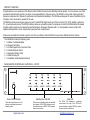
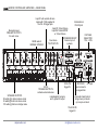
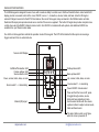
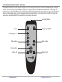
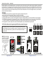
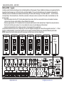
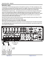
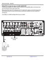
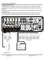
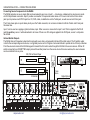
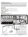
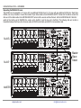
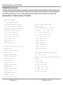
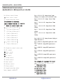
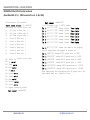
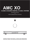
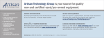
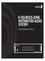
6-SOURCE 6-ZONE
DISTRIBUTED AUDIO
SYSTEM
Model: DAX66 User Manual
SAFETY INSTRUCTIONS
!
RISK OF ELECTRIC SHOCK
DO NOT OPEN
WARNING! TO REDUCE THE RISK OF
FIRE OR ELECTRIC SHOCK, DO NOT
EXPOSE THIS APPLIANCE TO RAIN
OR MOISTURE.
CAUTION! TO REDUCE THE RISK OF
SHOCK, DO NOT REMOVE THE COVER,
NO USER SERVICABLE PARTS INSIDE.
REFER SERVICE TO A DAYTON AUDIO
AUTHORIZED DEALER.
IMPORTANT SAFETY INSTRUCTIONS
• Read and keep these instructions.
• Heed all warnings and follow all instructions contained within this manual.
• Do not use this unit near water.
• Clean only with dry cloth.
• Do not block any ventilation openings. Install in accordance with the manufacturer’s instructions.
• Do not install near any heat sources such as radiators, heat registers, stoves, or other apparatus (including amplifiers) that produce heat.
• Do not defeat the safety purpose of the polarized or grounding-type plug. A polarized plug has two blades with one wider than the
other. A grounding type plug has two blades and a third grounding prong. The wide blade or the third prong are provided for your safety.
If the provided plug does not fit into your outlet, consult an electrician for replacement of the obsolete outlet.
• Protect the power cord from being walked on or pinched particularly at plugs, convenience receptacles, and the point where they exit
from the unit.
• Only use attachments/accessories specified by the manufacturer.
• Unplug this unit during lightning storms or when unused for long periods of time.
• Refer all servicing to qualified service personnel. Servicing is required when the unit has been damaged in any way, such as when the
power-supply cord or plug is damaged, liquid has been spilled, or objects have fallen into the unit, the unit has been exposed to rain or
moisture, does not operate normally, or has been dropped.
• Operate the unit only with the voltage specified on the rear. Fire and/or electric shock may result if a higher voltage is used.
• Do not modify, kink, or cut the power cord. Do not place the power cord in close proximity to heaters and do not place heavy objects
on the power cord and/or the unit itself, doing so may result in fire or electrical shock.
• Do not touch the speaker terminals as electric shock may result.
• Ensure that the safety ground terminal is connected to a proper ground. Never connect the ground to a gas pipe, as a severe explosion
and/or fire may result.
• Be sure the installation of this product is stable, avoid unlevel surfaces as the product may fall and cause injury, property damage,
electrocution and/or fire.
• Note that when the unit is turned off, it is not completely disconnected from the AC power outlet. Do not open the cover.
REFER ALL SERVICE TO A QUALIFIED SERVICE TECHNICIAN
daytonaudio.com
[email protected]
PRODUCT OVERVIEW
Congratulations on your purchase of the Dayton Audio DAX66 6-Source 6-Zone Distributed Audio System. You have chosen a unit that
provides the ultimate audio control in six stereo zones (expandable to 18 stereo zones). The DAX66 is a true matrix audio system that
delivers an extensive list of features for professional and residential installations. The DAX66 was designed for ease of installation by the
integrator, and to be simple to operate for the user.
The DAX66 provides six analog line inputs, and one Toslink S/PDIF digital audio input. Play music from CD, DVD, satellite or cable box,
PC, or personal audio device. The RS232 interface allows an automation system to manage and control the DAX66. Built-in IR repeater
provides a path to control source devices through the IR target in the keypad. Operates with 4 ~ 8 ohm speakers in stereo mode, 8 ohm
speakers in bridged mono mode, and provides a generous level of output power.
!
Please read and retain this manual to get the most from your Dayton Audio DAX66 6-Source 6-Zone Distributed Audio System.
The DAX66 kit includes the following parts:
1. 1 x Master Controller/Amplifier
2. 6 x Keypad Controllers
3. 1 x In-Wall Keypad Hub Connection Plate
4. 1 x Infrared Remote Control
5. 1 x Expansion Ribbon Cable
6. 1 x Rack Mounting Kit
7. 1 x Installation Guide/Operation Manual
DAX66 MASTER CONTROLLER / AMPLIFIER — FRONT
Power On/Off/Standby
Press the power button to turn the
system on and place all zones in
stand-by mode.
daytonaudio.com
Standby/Zone ON LED
All zones are in standby mode until activated
by a keypad. A BLUE LED indicates a zone
is in standby mode, a WHITE LED indicates
that a zone is active.
Peak LED
The PEAK LED indicates a connected
source level is too high. If the PEAK LED
emits a flashing or steady RED light, reduce
the zone input or output level.
[email protected]
MASTER CONTROLLER / AMPLIFIER — REAR PANEL
Stereo line-level
PRE-AMP OUTPUTS
for each zone
Input #1 will override all zone
inputs with 12Vdc applied to
the PA - IN trigger jack
Input #5: 3.5mm Stereo
Input #6: Toslink S/PDIF
or 3.5mm Stereo
MODE switch:
BRIDGE / STEREO
Four stereo
"RCA" INPUTS
12VDC
TRIGGER OUTPUTS
activate external devices
SPEAKER OUTPUTS
50 watts @ 4 ohms in stereo mode
25 watts @ 8 ohms in stereo mode
100 watts @ 8 ohms in bridge mode
Bi-directional
RS-232 port
EXPANSION IN/OUT;
Connect up to 3
systems
12Vdc PA
trigger IN
6-dedicated IR outputs
and 1-global IR output
KEYPADS
AC Input
Input connects
to keypad hub
Automatic Gain Control
brings low input levels
up to a pre-set level
12Vdc MUTE
trigger IN
daytonaudio.com
VOLTAGE
SELECTOR
115V - 230V
[email protected]
DAX66 KEYPAD FEATURES
The DAX66 keypad is designed for ease of use with a maximum ability to control sound. Soft-touch backlit buttons and a backlit LED
display provide convenient control of the zone; ON/OFF, source 1 ~ 6 selection, volume, treble, and bass. A built-in IR target or
external IR target connected to the EXT-IR terminals on the rear of the keypad, relay commands to the DAX66 master controller.
Dedicated IR output jacks provide remote source control of the source equipment. The built-in IR target also provides complete zone
control when using the DAXRC infrared remote control. One DAXRC is included with each system, and additional DAXRC are
available from your Dayton Audio dealer.
Five LEDs on the keypad face indicate the operation mode of the keypad. The EXT LED indicates that the system is receiving a
trigger command from an external device.
Numeric LED Display
Ext/Mute/PA selection LED
Volume up/down LED
Source selection LED
Down, volume, treble, bass, un-mute
Source select 1 ~ 6 descending
Treble up/down LED
Bass up/down LED
Up, volume, treble, bass, un-mute
Source select 1 ~ 6 ascending
Power ON/OFF & mode select
Infrared (IR) target
Press and hold for zone on/off, press
to toggle through volume, source,
treble and bass adjustment mode.
Use the select button with the volume
up/down buttons to adjust volume levels,
treble and bass levels
The select button emits a soft glow
when the zone is powered off
daytonaudio.com
[email protected]
DAX66 INFRARED REMOTE CONTROL FEATURES
The DAXRC infrared remote control provides complete zone control through the IR receiver located on the DAX66 keypad. All keypad
functions can be accessed using the DAXRC. In addition to the keypad functions, the DAXRC has a MUTE button to temporarily mute
audio in the zone. Once the MUTE function is activated the keypad's LED display will flash, indicating the mute status. Press the MUTE
button to continue playing music, or press the keypad volume up or down buttons to un-mute the zone. One DAXRC is included with
each system, and additional DAXRC are available from your Dayton Audio dealer.
!
Infrared IR Emitter
Mute
Source toggle 1 ~ 6
Treble up/down
Zone power ON/OFF
+
Bass up/down
Volume up/down
Balance left
daytonaudio.com
Balance right
[email protected]
DAX66 INSTALLATION — OVERVIEW
Install the DAX66 in a well-ventilated location; do not block the vents on the sides or top of the chassis, proper ventilation is required for
normal operation. Do not expose the unit to excessive dust and do not allow dust to build up on the unit and block the vent holes in the
chassis. Do not place the DAX66 above or below heat-generating components such as another audio amplifier. Be sure to leave at least
2 inches of space to the sides of the chassis with open air flow above and below the unit. Due to the weight of the unit, we recommend
using four-post racks at minimum.
OVERVIEW:
1. The DAX66 can be mounted in an equipment rack using the included rack mount kit.
2. Always disconnect AC power before making connections to the DAX66.
3. Use good quality 12 or 14 AWG stranded copper speaker wire for all speaker connections.
4. Use good quality cable for connection of the keypads to the master controller/amplifier; we recommend Cat5e to connect keypads.
5. The DAX66 uses a keypad hub; all keypads will connect to the hub. Install the keypad hub close to the master controller/amplifier.
For ease of installation, the keypads and the keypad hub are fitted with quick-disconnect screw terminal blocks.
6. The keypad hub connects easily to the master controller/amplifier using a standard Ethernet patch cable.
ZONE-1
NOTE: Set the Address of each keypad using the DIP switches on back of the keypad.
Each keypad must have a distinct address to communicate correctly with the
controller/amplifier. Select zone address numbers 1 through 6 by using the chart
to the right. A DIP switch in the up position is ON; a DIP switch in the down
position is OFF.
ON ON OFF
ON
1 2 3
ON
ON
ZONE-3
ON
OFF
1 2 3
1 2 3
1 2 3
ZONE-4
ZONE-5
ZONE-6
ON ON
ON OFF
OFF ON
1 2 3
1 2 3
1 2 3
NOTE: When attaching
a keypad to an electrical
box, use a screwdriver
to reduce the chance of
damage to the keypad.
daytonaudio.com
ZONE-2
[email protected]
DAX66 INSTALLATION — KEYPADS
INSTALLATION Keypads
Use high quality Cat5e/6 cable between the controller/amplifier and the keypads. Proper installation techniques will guarantee that the
keypads will work properly up to 600 feet from the controller/amplifier. The use of terminal blocks on the keypads and keypad hub
ultimately reduces the frustration associated with terminating UTP cable with RJ45 plugs. The PCB is labeled 1 ~ 6 at the location
corresponding to the terminal blocks. Attach the conductors in the same order on each end of the cable. See illustrations on the
previous page.
• Strip the insulation from the UTP (Cat 5e cable) about three inches. Don't be concerned that too much insulation has been
removed since the wire will be hidden in the wall behind the keypad.
• Remove approximately 1/4" of insulation from the conductors and insert into the terminal block. Tighten the screw terminal on
the block to hold the wire in place. Do not over tighten the screw to avoid stripping out the terminal.
• Attach the terminal block to the mating connector on the keypad or the keypad hub.
Use standard electrical boxes or low voltage rings to mount the keypads and keypad hub. Mount the keypad hub less than 7 ~ 10 feet
from the controller/amplifier. Connect the keypad hub to the master controller/amplifier using a standard Ethernet patch cable.
NOTE: Always follow local building codes and use proper electrical boxes and low voltage rings.
!
*
Cat5e/6
7~10 feet
daytonaudio.com
[email protected]
DAX66 INSTALLATION — SPEAKERS
INSTALLATION — Speakers
Use good quality 12-14 AWG stranded copper speaker wire. Most jurisdictions require the use of CL2 rated in-wall speaker wire, refer to
your local building code enforcement office for the proper cable type for your installation. If speaker wires must be run parallel to AC wires,
keep the speaker wires and AC wires at least 10 inches apart. If you must cross AC wires, always cross at a 90 degree angle.
The DAX66 amplifiers are capable of driving 4 ~ 8 ohm speaker loads in stereo mode, and 8 ohm loads in bridge mode. Never connect
more than two 8 ohm speakers wired in parallel to a single amplifier channel in stereo mode. Never connect more than one 8 ohm
speaker to a single channel in bridge mode. Never connect the Left & Right channels of the amplifier together or combine the (–) negative
channels of the amplifier. Improper speaker installation can damage the amplifiers and void the warranty. If you are unsure how to
connect speakers to the DAX66, contact a qualified technician.
Remove the terminal block connector and make sure that all contacts are open by turning each set screw counter clockwise. This helps
insure that the speaker wire will not fray when inserted into the terminal.
!
INSTALLATION: Connecting 8 ohm speakers to the DAX66 in STEREO MODE
Set the amplifier mode switch to STEREO. Remove approximately 5 inches from the cable jacket, strip 1/4" of insulation from the speaker
wire, and twist the copper strands. Insert the speaker wires into the connector per the label below the output terminals and tighten the set
screws. Repeat for the remaining zones.
Left
Set the MODE switch
to STEREO
4 ~ 8 ohm
speakers
daytonaudio.com
[email protected]
DAX66 INSTALLATION — SPEAKERS
INSTALLATION: Connecting 8 ohm speakers to the DAX66 in BRIDGE MODE
In BRIDGE mode the amplifier LEFT and RIGHT outputs are combined into one large MONO amplifier, thus doubling the output
power to 50 watts with a minimum speaker load of 8 ohms.
Remove approximately 5 inches from the cable jacket, strip 1/4" of insulation from the speaker wire, and twist the copper strands.
Insert the speaker wires into the connector per the label below the output terminals and tighten the set screws. Repeat for the
remaining zones.
It is permissible to mix STEREO and Bridged MONO outputs on one DAX66.
Set the MODE switch
to BRIDGE
MONO
- +
8 ohm
speaker
daytonaudio.com
[email protected]
DAX66 INSTALLATION — PRE-AMP OUTPUTS
Using the DAX66 PRE-AMP OUTPUTS
The DAX66 provides six stereo, unbalanced, line level PRE-AMP outputs, which correspond to the six-zone outputs. The PRE-AMP
outputs can be used to connect powered subwoofers to a zone or additional amplifiers to expand the available power in a large zone or
multiple zones.
The DAX66 can be used as the master controller in large commercial audio systems with constant voltage 25/70V amplifiers connected
to the PRE-AMP outputs.
The PRE-AMP output levels are variable and are controlled from the DAX66 keypad, Infrared remote, or RS232 from an automation
system. For best performance, the PRE-AMP output cables should be less than 25 feet long and be high-quality, shielded cables.
!
Stereo mode
4 ~ 8 ohm
speakers
70 volt speakers
Powered Subwoofer
daytonaudio.com
[email protected]
DAX66 INSTALLATION — CONNECTING SOURCES
Connecting Source Components to the DAX66
The DAX66 provides six source inputs that can be accessed by any zone. Inputs 1 ~ 4 are stereo, unbalanced, line level source inputs
via RCA style female connectors. Input 5 provides a connection for a personal audio device or PC sound card via the 3.5mm stereo
jack. Input 6 provides one S/PDIF input for a CD, DVD, cable, or satellite box via the Toslink jack, as well as a second 3.5mm jack.
!
The 3.5mm stereo jack on input 6 takes priority over the Toslink connector; do not connect cables to both the Toslink and 3.5mm jack
the same time.
Input 1 can be used as a paging or global; all-zones, input. When a source is connected to input 1 and 12Vdc is applied to the PA-IN
jack (tip positive), source 1 will be broadcast to all zones. If there is no DC voltage is applied to the PA-IN jack, source 1 will operate
like normal.
Infrared Emitter Outputs
The DAX66 has an IR repeater system built-in and each source has a corresponding Infrared (IR) emitter output. The IR emitter output
is tied to the corresponding source device, or all (global) source control. Program a universal remote to operate all six of the input devices.
Point the universal remote at the DAX66 keypad to transmit the IR control codes through the DAX66 to the source devices. With an IR
emitter connected to an IR EMITTER output jack and the emitter placed over the source device IR receiver window, the source devices
can be controlled from any zone.
CD, DVD or Music Player
COAX
RCA
(OPTICAL)
POWER
SATELLITE IN
IR Emitter
daytonaudio.com
3.5mm
Stereo
S-VIDEO OUT
VIDEO OUT
AUDIO OUT
DIGITAL
AUDIO OUT
HDMI
ETHERNET
Digital Optical
[email protected]
SATA
PHONE LINE
DAX66 INSTALLATION — 12V TRIGGERS
Using the DAX66 12VDC Trigger Inputs and Outputs
The DAX66 provides six 12Vdc trigger outputs which correspond to the six DAX66 zones. When a zone is powered ON by the DAX66
keypad, the corresponding zone sends 12Vdc to the trigger output jack. When the zone is powered OFF, 12Vdc is disconnected from the
trigger output. The triggers can be used to automatically switch peripheral equipment ON/OFF. The DAX66 also provides a master control
12Vdc trigger output that sends 12Vdc to the CONTROL OUT jack when any zone is powered ON and disconnects the 12Vdc when all
zones are powered off.
DAX66 Trigger outputs:
ZONES 1 ~ 6: Zone ON; 12Vdc applied to the TRIGGER OUTPUT, Zone OFF; 12Vdc
removed from the TRIGGER OUTPUT.
CONTROL: Any zone ON; 12Vdc applied to the CONTROL OUT, All zones OFF; 12Vdc
removed from the CONTROL OUT
DAX66 Trigger Inputs:
PA- IN: Apply 12Vdc for input #1 override on all six zones.
MUTE – IN: Apply 12Vdc to mute all zones.
!
To Projection
Screen 12 Vdc
Trigger In
Motorized Projection Screen
daytonaudio.com
External Amplifier Control
To External
Amplifier
12VDC Trigger In
WIRING: 3.5mm Mono
Plug: Tip Positive.
[email protected]
DAX66 INSTALLATION — EXPANSION
Expanding the DAX66 to 18 zones
The DAX66 can be expanded to 12 zones with one additional DAX66 kit and to 18 zones with two additional DAX66 kits. Stack three
DAX66, one on top of another. Connect the included 18-pin ribbon cable to the EXPANSION OUTPUT terminal of the bottom unit and the
other end of the ribbon cable to the EXPANSION INPUT terminal of the second and then third unit. Set the MASTER/SLAVE-1/SLAVE-2
switch of the bottom unit to MASTER, the center unit to SLAVE-1, and the top unit to SLAVE-2. The following data and control is
transmitted between the three units; all source audio, all RS232 control data, and all MCU communication data.
!
SLAVE 2
Master
Slave
Select
SLAVE 1
MASTER
daytonaudio.com
[email protected]
DAX66 INSTALLATION — RS-232 CONTROL
DAX66 RS-232 Serial Port Control
The DAX66 provides an RS-232 serial port for connection to and control by automation systems. The DB-9 connector on the back of the
unit supports bi-directional RS-232 communication for third party automation systems. An automation system can control all keypad and
remote control functions for up to 18 zones (3 master controller units), linked together using the included 18 pin expansion cable.
(Baud Rate 9600, 8, N, 1, DB9 Connector Pin out, TX, RX, GND)
!
DAX66 RS-232 CONTROL
'CR':Carriage Return (0x0D)
No case capitalization/ lowercase
Control order structure <xxPPuu'CR'
Reply control order frame >xxPPuu'CR'
xx: stands for control object code
10 :All Zone of Main unit 1.
20 :All Zone of Main unit 2.
30 :All Zone of Main unit 3.
:Zone1 of Main unit 1.
:Zone2 of Main unit 1.
:Zone3 of Main unit 1.
...............
PP: Stands for control action code.
PR:Power control
PR00:Power off PR01:Power on
MU:Mute control
MU00:Mute off MU01:Mute on
DT:Do Not Disturb control
DT00:DT control off
DT01:DT control on
VO:Volume control
VO(00-38):Volume control
TR:Treble control
TR(00-14):Treble control
BS:Bass control
BS(00-14):Bass control
BL:Balance control
BL(00-20):Balance control
daytonaudio.com
CH:Source Channel control CH(0106):Source control
Inquiry command structure (1) ?xx'CR'
xx: stands for control object code
10 : All Zone of Main unit 1.
20 : All Zone of Main unit 2.
30 : All Zone of Main unit 3.
: Zone1 of Main unit 1
: Zone2 of Main unit 1
: Zone3 of Main unit 1
: Zone1 of Main unit 2
: Zone2 of Main unit 2
: Zone3 of Main unit 2
...............
Reply command: >xxaabbccddeeffgghhiijj'CR'
aa: PA control status
bb: Power control status ([5]:Backup Zone Power
Status
(only on zone)
cc: Mute control status
dd: DT control status
ee: Volume control status
ff: Treble control status
gg: Bass control status
[email protected]
DAX66 INSTALLATION — RS-232 CONTROL
DAX66 RS-232 Serial Port Control continued.
(Baud Rate 9600, 8, N, 1 , DB9 Connector Pin out, Tx, Rx, GND)
!
hh: Balance control status
Source control status
jj: keypad connecting status
xx:
20
30
11
12
13
14
16
All Zone
All Zone
All Zone
Zone1 of
Zone2 of
Zone3 of
Zone4 of
Zone5 of
: Zone6 of
:
:
:
:
:
:
of Main unit
of Main unit 2.
of Main unit 3.
Main unit 1
Main unit 1
Main unit 1
Main unit
Main unit
Main unit 1
PP: Stands for control action code.
PA: PA control
Power control
Mute control
DT control
VO: Volume control
TR: Treble control
BS: Bass control
BL: Balance control
CH: Source control
LS: keypad connecting status
Reply command: >xxPPuu'CR'
Key in 1<********'CR' change Source 1 Name
display;********needs to be 8 valid ASCII codes.
Key in 2<********'CR' change Source 2 Name
display
Key in
3<********'CR' change Source 3 Name
display
Key in
4<********'CR' change Source 4 Name
display
Key in
5<********'CR' change Source 5 Name
display
Key in
6<********'CR' change Source 6 Name
display
Key in
keypad
Key in
Key in
19200
Key in
38400
Key in
57600
Key in
115200
Key in
230400
M<********'CR' change the name display on
when turn on.
<9600'CR' change RS232 speed rate to 9600
<19200'CR' change RS232 speed rate to
<38400'CR' change RS232 speed rate to
<57600'CR' change RS232 speed rate to
<115200'CR' change RS232 speed rate to
<230400'CR' change RS232 speed rate to
cord, the baud speed rate returns to 9600.
ee:
jj:
daytonaudio.com
[email protected]
DAX66 INSTRUCTIONS — RS-232 CONTROL
DAX66 RS-232 Serial Port Control continued
(Baud Rate 9600, 8, N, 1 , DB9 Connector Pin out, Tx, Rx, GND)
!
(00:disconnect 01:connected)
(2) ?xxPP'CR'
xx: stands for control object code
10 : All Zone of Main unit 1.
20 : All Zone of Main unit 2.
30 : All Zone of Main unit 3.
11 : Zone1 of Main unit 1
12 : Zone2 of Main unit 1
13 : Zone3 of Main unit 1
14 : Zone4 of Main unit 1
15 : Zone5 of Main unit 1
16 : Zone6 of Main unit 1
PP:
PA:
PR:
MU:
DT:
VO:
TR:
BS:
BL:
CH:
LS:
Stands for control action code.
PA
Power
Mute
DT
Volume
Treble
Bass
Balance
Source
keypad connecting status
: >xxPPuu'CR'
daytonaudio.com
: >xxPPuu'CR'
;********needs to be 8 ASCII codes.
1<********'CR' change Source 1
2<********'CR' change Source 2
3<********'CR' change Source
4<********'CR' change Source
5<********'CR' change Source 5
6<********'CR' change Source 6
M<********'CR' change the name in the display
On the keypad when the keypad is turned on.
<9600'CR' change RS232 speed rate to 9600
<19200'CR' change RS232 speed rate to 19200
<38400'CR' change RS232 speed rate to 38400
<57600'CR' change RS232 speed rate to 57600
<115200'CR' change RS232 speed rate to 115200
<230400'CR' change RS232 speed rate to 230400
unplugging
and re-plugging the AC power cord, the
When
Baud speed rate will return to 9600.
[email protected]
DAX66 SPECIFICATIONS & WARRANTY
!
!
!
RMS Power @ 8 ohms
25 watts x 12
RMS Power @ 4 ohms
50 watts x 12
RMS Power @ 8 ohms Bridge
Mode
100 watts x 6
S/N Ratio
>85dB A Weighted
THD
<0.1%
Frequency Response
20 ~ 20,000 Hz
Input Impedance
>47K ohms
Input Sensitivity
250mv
Amplifier Protection
Overload, Short Circuit & Thermal
Trigger Systems ON Voltage
DC + 12V
Trigger External Mute Voltage
DC + 12V
Infrared Frequency Band
38kHz
Input Connectors
3.5mm stereo, RCA, Toslink
Output Connectors
Terminal Block, RCA
Power Supply (switchable)
AC115V/60Hz, 230V/50Hz
Dimensions
16.9" (W) x 3.5" (H) x 16.4" (D)
Weight
24.25 lbs.
Warranty
5 Years
daytonaudio.com
Specifications are subject to change from time to time
without notice.
Contact Information:
Dayton Audio
705 Pleasant Valley Drive
Springboro, OH 45406
PH: 937-743-8248
E-Mail: [email protected]
Web: www.daytonaudio.com
Warranty
This Dayton Audio® product is warranted free from defects
in material and workmanship for a period of five years from
date of purchase. Product registration is not required;
however keep the original invoice as proof of purchase.
Warranty does not apply to misuse, abuse, neglect,
accident, improper use, etc.
To process a return or have your product replaced under
warranty, please contact your Dayton Audio reseller to
to obtain an RA #. Pack merchandise carefully to avoid
further damage and complete the Return Form on the bottom
of the invoice. Record customer and RA numbers on the
outside of the box. Ship merchandise back to your Dayton
Audio reseller prepaid.
[email protected]
© Dayton Audio® Last Revised: 4/20/2015