1
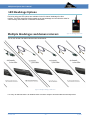
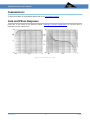
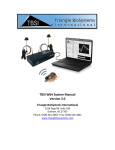
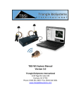
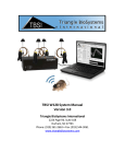
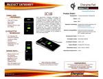
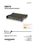
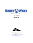
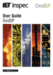
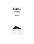
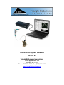
TBSI M Series System’s Manual
Version 3.0
Triangle BioSystems International
2224 Page Rd. Suite 108
Durham, NC 27703
Phone: (919) 361-2663 • Fax: (919) 544-3061
www.trianglebiosystems.com
Multiplexed System User’s Manual
Contents
32 CHANNEL MULTIPLEXING HEADSTAGE SYSTEMS ............................................................................................................... 3
Introduction ............................................................................................................................................................................. 3
Features ................................................................................................................................................................................... 3
System Configuration .............................................................................................................................................................. 4
Multiplexed Headstage Specifications ..................................................................................................................................... 4
Multiplexer System Parts List .................................................................................................................................................. 5
Headstage Specifications ......................................................................................................................................................... 6
Headstage Mechanical Overview ............................................................................................................................................ 7
32 Channel Headstage Pinout.................................................................................................................................................. 7
Demultiplexer Base Station Specifications .............................................................................................................................. 8
Demultiplexer Base Station Mechanical Overview .................................................................................................................. 8
Demultiplexer Base Station Interface Options ........................................................................................................................ 8
Demultiplexer Base Station Analog Output ............................................................................................................................. 9
Demultiplexer Base Station Digital Interface ........................................................................................................................ 10
System Setup and Testing ...................................................................................................................................................... 11
Headstage Accessory Options................................................................................................................................................ 12
LED Headstage Options.......................................................................................................................................................... 13
Multiple Headstages and demux recievers............................................................................................................................ 13
Commutators ......................................................................................................................................................................... 14
Gain and Phase Response ...................................................................................................................................................... 14
Troubleshooting ..................................................................................................................................................................... 15
Application Notes .................................................................................................................................................................. 15
Contact Us.............................................................................................................................................................................. 15
Version 3.0
-2-
8/2014
Multiplexed System User’s Manual
32 CHANNEL MULTIPLEXING HEADSTAGE SYSTEMS
Introduction
Figure 1: Multiplexing Headstage System
Triangle BioSystems International (TBSI) offers a multiplexed analog headstage that is used to provide a reduced
wired connection between implanted electrodes, neural recording and analysis equipment. The main function of
the headstage is to precondition the neuron pulse signals and provide a high gain, bandpass filtered buffered
connection over a 3 wire cable. Each headstage design is based on a custom, low power VLSI developed by TBSI.
The result is a solution with superior performance and reduced wire connection in a very small form-factor with
less weight.
The 32 channel high gain, bandpass filter headstages are available with system gain of 800 with an adjustable
bandpass filtering from the factory.
Features
•
3 wire interface cable for 32 channels with typical of
2 to 3 feet length
•
•
32ch: Size:5x15x20 mm @ 0.8 grams
•
•
•
•
Options for multiple headstages providing 62, 93,
124, 155, 186, 207 recording channels with 4, 5, 6,
7, 8, 9 wired cables respectively.
Available with system gain of 800
Bandpass filtering of .8Hz to 7khz
Optional Blue, Red and Green LED available for
video tracking
Option to choose between both Analog and/or
Digital outputs
Version 3.0
Figure 2: Headstage and Base Station
-3-
8/2014
Multiplexed System User’s Manual
System Configuration
See the section entitled System Setup and Testing for more details on proper system assembly and positioning.
Figure 3: TBSI Multiplexed Recording Setup
Multiplexed Headstage Specifications
The multiplexed neural headstage system consists of a Tethered Headstage, Slip-ring Commutator, and
Demultiplexer Base Station as shown below:
Figure 4: Multiplexed Headstage System Flow Diagram
Version 3.0
-4-
5/2015
Multiplexed System User’s Manual
Multiplexer System Parts List
Figure 5: Multiplex System Parts
Multiplexer System Parts List
Item #
Part Number
1
Various
2
Various
3
Various
4
Various
5
6
7
8
Version 3.0
100-0000-11
202-0001-10
008-0012-01
200-0011-00
Description
Headstage
Commutator
Demultiplexed Base Station
Multiplexer Test Cable
Base Station 6 VDC power supply 120 VAC/240 UL and FCC
approved
DB37 Connector
Headstage Shorting Plug (For M64 and up)
Earth Ground Cable
-5-
5/2015
Multiplexed System User’s Manual
Headstage Specifications
PARAMETER
Power Supply
Headstage Pwr supply
Average I cc 3.0V
Analog Channel
Max Input voltage
range
Max Output Voltage
range
Common mode center
DC Offset
System Gain 800
Bandwidth @ 3V
Input impedance
Output impedance
MIN
TYP
MAX
UNITS
2.99
3.0
3.01
V
5.6
6.1
6.7
mA
-2
-1.2
-10
790
.8
0
0
800
+2
mV
+1.2
V
V
10
810
7000
mV
Hz
11
158
MΩ
Ω
Input referred noise
8.5
µVrms
Input referred noise
Channel sample Rate
THD
Phase Delay
Headstage Mechanical
Measurements (Length,
Width, Height)
5.5
50
µVrms
Weight
Version 3.0
kHz
-63
dB
30
24
14
µSecs
3
mm
2.7
g
-6-
NOTES
3.0 Bipolar power (+2.1V, -.9V and ACgnd
@ 0V)
Without LEDs
For gain of 800 System (headstage gain of
100)
Measured at DB37 connector of Base
Station
ACgnd @ 0V
For Bipolar power supplies only
Factory default gain
-3dB input signal level BW
At 1kHz
At 1khz
For DC – 10khz frequency with all inputs
grounded
For 500Hz – 5kHz frequency with all inputs
grounded
Per-channel sampling rate
@5kHz and 1 volt p-p input
@ 5kHz input
Dimensions of 32ch headstage board only
Headstage only (wire not included in
weight)
5/2015
Multiplexed System User’s Manual
Headstage Mechanical Overview
Top View
Bottom View
Figure 6: Headstage Mechanical Overview
Complete headstage weight is 2.7 g (coated) or 3.4 grams (standard version)
32 Channel Headstage Pinout
Pin #
1
2
3
4
5
6
7
8
9
10
11
12
13
14
15
16
17
18
Pin Connection
GND
Channel 17
Channel 18
Channel 19
Channel 20
Channel 21
Channel 22
Channel 23
Channel 24
Channel 25
Channel 26
Channel 27
Channel 28
Channel 29
Channel 30
Channel 31
Channel NC
GND
Pin #
19
20
21
22
23
24
25
26
27
28
29
30
31
32
33
34
35
36
Pin Connection
GND
Channel 1
Channel 2
Channel 3
Channel 4
Channel 5
Channel 6
Channel 7
Channel 8
Channel 9
Channel 10
Channel 11
Channel 12
Channel 13
Channel 14
Channel 15
Channel 16
GND
.025” Omnetics Female
TBSI P/N: A9409
Mating Male Electrode Connector
TBSI P/N: A9707
Version 3.0
-7-
5/2015
Multiplexed System User’s Manual
Demultiplexer Base Station Specifications
•
•
•
•
•
Input referred noise, typical: 4 µV RMS
Input voltage range: +/- 0.5 V
Analog channel bandwidth: 7 kHz
DC offset: < 100 µVDC
Phase delay typical: 30 µsec at 10 kHz
Demultiplexer Base Station Mechanical Overview
Figure 7: Demultiplexer Base Station Overview
Demultiplexer Base Station Interface Options
The Base Station is available in many different configurations to accommodate a wide range of data acquisition interface
requirements. Custom interface cables for adaption to other Data Acquisition Systems are available upon request and
purchase. There are three configurations which are a composition of analog and digital output configurations. The first is
purely a digital output, the second is a purely analog output and the third is a combination of digital and analog.
Version 3.0
-8-
5/2015
Multiplexed System User’s Manual
Demultiplexer Base Station Analog Output
Pin #
1
2
3
4
5
6
7
8
9
10
11
12
13
14
15
16
17
18
19
20
21
22
23
24
25
26
27
28
29
30
31
32
33
34
35
36
37
Figure 8: Demultiplexer Base Station Output Image
Version 3.0
-9-
Description
GND
Channel 30 Output
Channel 28 Output
Channel 26 Output
Channel 24 Output
Channel 22 Output
Channel 20 Output
Channel 18 Output
Channel 16 Output
Channel 14 Output
Channel 12 Output
Channel 10 Output
Channel 8 Output
Channel 6 Output
Channel 4 Output
Channel 2 Output
No Connect
No Connect
No Connect
Channel 31 Output
Channel 29 Output
Channel 27 Output
Channel 25 Output
Channel 23 Output
Channel 21 Output
Channel 19 Output
Channel 17 Output
Channel 15 Output
Channel 13 Output
Channel 11 Output
Channel 9 Output
Channel 7 Output
Channel 5 Output
Channel 3 Output
Channel 1 Output
GND
No Connect
5/2015
Multiplexed System User’s Manual
Demultiplexer Base Station Digital Interface
TBSI offers an internal DAQ board option and NeuroWare™ software which can be used for data acquisition and analysis.
The DAQ board information is sent to the PC via a USB connection.
Figure 9: TBSI NeuroWare Screen Shot
Version 3.0
- 10 -
5/2015
Multiplexed System User’s Manual
System Setup and Testing
The steps below should be followed when setting up your Multiplex system to optimize its
performance.
1) Connect power supply to de-multiplexer Base Station
Plug the DC end of the power supply cable into the Base Station. The Base Station is powered by an AC line wall
adapter. Use a suitable International adapter to mate the standard US plug to your AC outlet.
Figure 10: Power Supply Image
2) Connect signal output cable to Base Station analog output DB37 connector
If you have an Analog Output Base Station, connect the analog output cable to the DB37 connector. It can be
added to the DB37 mating connector to check for signal output. The lengths of the wires are not critical. The
analog output channel positions are described in the section entitled Base Station Signal Interface – Analog
Output.
If you have a Digital Base Station, plug the USB cord into the Base Station and PC and follow the instructions
provided in the Neuroware Manual or your data acquisition software for signal acquisition and viewing.
3) Turn on Base Station
Turn on Base Station, the power light will illuminate.
4) Connect a function generator to the headstage via headstage signal cable
Once the Base Station and headstage (see #7 below) have both been switched on, the “Signal Lock” LED on the Base
Station front panel should light up. After confirming the signal lock integrity, you can view the analog signals (output
from the DB37 connector on the back of the Base Station) with an oscilloscope. Please note the default system gain is
800, therefore you can expect the analog output values to be about 800 Vp-p of the signal from the function generator.
Connect function generator to test cable with an input of 1kHz Sine Wave signal at maximum 4m Vp-p amplitude.
Figure 11: Headstage and Signal Cable
Version 3.0
- 11 -
5/2015
Multiplexed System User’s Manual
Headstage Accessory Options
Three optional biosensors. These accessories replace channels typically used for neural recording on the headstage. The
features can be installed individually or together in any combination. See the TBSI Biosensors Brochure for more
information.
Accelerometer
This accelerometer will measure x, y, and z acceleration and outputs the information via three recording channels.
Ultrasonic Microphone
This single ultrasonic microphone enables recording of audio frequencies between 1 kHz and 35 kHz using one recording
channel.
Temperature Sensor
A Thermistor temperature sensor option is available. The sensor must be attached to a mating connector and externalized
to the head of the animal much like traditional recording electrodes. This sensor utilizes one recording channel.
Figure 12: Headstage with Temperature Sensor
Version 3.0
- 12 -
5/2015
Multiplexed System User’s Manual
LED Headstage Options
Red, blue and green LED options are available for the 32 channel headstage for video
tracking. The LEDs are placed facing upward on the top headstage and are utilized to allow for
video tracking. Both LEDs turn on with the On/Off switch.
Multiple Headstages and demux recievers
Figure 13: Headstage with LED's
The 32, 64, 96 and 128 channel M-series are shown below:
Figure 14: Multiple Headstages and Receivers
For every 32 channels there is an addition DB37 Connector output to accommodate the new output load.
Version 3.0
- 13 -
5/2015
Multiplexed System User’s Manual
Commutators
To learn more about our commutators please refer to our commutator brochure.
Gain and Phase Response
Please refer to the section of this document entitled “Headstage Transmitter Specifications” for numerical data on
bandwidth and input referred noise.
Figure 15: Gain and Phase Response Graphs
Version 3.0
- 14 -
5/2015
Multiplexed System User’s Manual
Troubleshooting
Problem:
Suggestion:
No neural signals are visible on any of the analog outputs at the DB37 connector.
Verify the AC power connection is in place and the green “Power” LED is
illuminated on the front of the Base Station box.
Problem:
Suggestion:
Not all channels are visible on the neural signal.
Make sure the headstage connection to the animal is secure.
Application Notes
1) If you do not intend to record from all of the available signal channels you must ground any unused channels at the
electrode connector or EIB interface. Failure to do so can create artifact noise from the floating channels on the
other signal channels.
Contact Us
Triangle BioSystems International
2224 Page Rd. Suite 108
Durham, NC 27703
Phone: (919) 361-2663 • Fax: (919) 544-3061
www.trianglebiosystems.com
Need more help? You can reach TBSI customer support by phone at the number listed above (M-F
Eastern US Time) or email us at [email protected]. If you need replacement parts
or accessories for your system or to learn the latest about available TBSI products visit our website,
call or email us at [email protected].
Version 3.0
- 15 -
5/2015