1
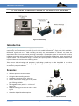
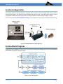
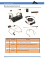
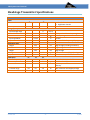
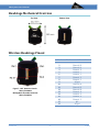
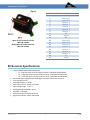
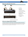
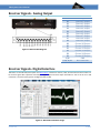
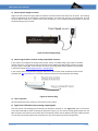
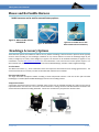
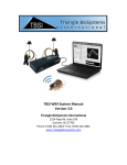
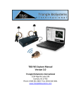
TBSI W16 System Manual
Version 3.0
Triangle BioSystems International
2224 Page Rd. Suite 108
Durham, NC 27703
Phone: (919) 361-2663 • Fax: (919) 544-3061
www.trianglebiosystems.com
W16 System User’s Manual
Contents
16 CHANNEL WIRELESS NEURAL HEADSTAGE SYSTEM ........................................................................... 3
Introduction ............................................................................................................................................. 3
Features ................................................................................................................................................... 3
System Configuration ............................................................................................................................... 3
System Block Diagram.............................................................................................................................. 3
Wireless System Parts List ....................................................................................................................... 4
Headstage Transmitter Specifications ..................................................................................................... 5
Headstage Mechanical Overview ............................................................................................................ 6
Wireless Headstage Pinout ...................................................................................................................... 6
RF Receiver Specifications ....................................................................................................................... 7
RF Receiver Mechanical Overview ........................................................................................................... 8
RF Receiver Signal Interface Options ....................................................................................................... 8
Receiver Signals - Analog Output ............................................................................................................. 9
Receiver Signals– Digital Interface ........................................................................................................... 9
System Setup and Testing ...................................................................................................................... 10
Internal and External Batteries .............................................................................................................. 13
Mouse and Rat Saddle Harness ............................................................................................................. 14
Headstage Accessory Options................................................................................................................ 14
LED Headstage Options .......................................................................................................................... 15
Wireless Power Headstage Option ........................................................................................................ 15
Electrodes .............................................................................................................................................. 15
Gain and Phase Response ...................................................................................................................... 15
Troubleshooting ..................................................................................................................................... 16
Application Notes................................................................................................................................... 16
Contact Us .............................................................................................................................................. 17
Version 3.1
-2-
7/2015
W16 System User’s Manual
16 CHANNEL WIRELESS NEURAL HEADSTAGE SYSTEM
Figure 1: System Setup
Introduction
The Triangle BioSystems International (TBSI) W16 wireless recording headstage system allows researchers to
continuously and simultaneously monitor up to 15 single ended biopotentials as single units, EEG and ECOG.
Differential signals such as an EMG recording can easily be accommodated in software. No longer do
experiments have to be constrained by tethering a test subject. The complete system is comprised of a wireless
headstage transmitter with integrated battery, RF signal receiver/baseband demodulator, power supply and all
required cables. With an effective range of 3 meters, this system provides a wireless connection between the
implanted electrodes and the data recording system.
TBSIs custom ASIC technology and proprietary radio design provide up to 7kHz bandwidth in a wireless
headstage that is both small and light weight (4 g). This design also incorporates preamplifier circuitry to create
an extremely compact headstage.
Features
•
•
•
•
•
•
•
Wireless operations across 3 meters
15 single ended recording channels
Headstage transmitter weight: 4.0 grams
Default Total System voltage gain of 800, other
gain offerings available
Rechargeable battery with 3.5 – 4.2 hours of
battery life
Bandpass filtering per channel at .8 Hz to 7 kHz
typical
Covered or dipped headstage options
Figure 2: Headstage
Figure 3: Receiver with Dual Antenna
Version 3.1
-3-
7/2015
W16 System User’s Manual
System Configuration
The receiver antennas must be clipped to a surface within 3 meters from the animal at all times to achieve
optimal signal quality. They should be positioned above the animal’s cage. Be careful not to obstruct the lineof-sight path between the animal and the receiver antenna with any material except for glass or plastic.
See the section entitled System Setup and Testing for more details on proper system assembly and positioning.
Figure 4: Standard TBSI Wireless Recording Setup
System Block Diagram
The wireless neural headstage system consists of a wireless transmitter headstage, an RF receiver and baseband
demodulation subsystems as shown below:
Figure 5: System Block Diagram
Version 3.0
-3-
3/2014
W16 System User’s Manual
Wireless System Parts List
Wireless System Parts List
Item #
Part Number
1
Various
2
Various
3
110-0001-00
4
300-0002-10
5
100-0000-10
6
100-00001-00
7
200-0021-10
8
300-0000-00
9
202-0001-10
10
200-0011-00
Version 3.0
Description
Headstage
Wireless Radio Receiver (Analog or Digital)
W-Series Receiver Antenna
Receiver Antenna Extension Cable and Mounting Clamp, 5 ft
Receiver 6 VDC power supply 120 VAC/240 UL and FCC approved
Record or Stim Wireless Headstage Battery Charger, 4.7 V
W16 Signal Input Test Cable, All Channels Combined, Single GND
Magnetic Wand, Headstage On/Off, 12 In
Male DB 37 Connector and housing
4 foot earth GND cable for receiver banana jack (Not Pictured)
-4-
3/2014
W16 System User’s Manual
Headstage Transmitter Specifications
PARAMETER
Power
Current Draw
MIN
13A
Battery
Analog Input Specs
Input voltage range
Gain Selection
Bandwidth
Input impedance
Input referred noise
Mechanical Specs
Length
Width
Height
Weight
Input connector
Radio Specs
Center frequency
Transmit power
Transmit antenna
Transmit range
Version 3.0
TYP
MAX
UNITS
NOTES
24B
mAh
A. Standard Version
B. High Power Version
mAh
60
790
0.8
800
4
810
7000
6.5 M
8.3
mVp-p
Hz
Ω
µVrms
22.2
16.5
14.2
4.0
4.2
F1
3.05
300
3.05
F2
3.375
300
3.375
F3
2.725
300
2.725
3.0
3.0
3.0
mm
mm
mm
g
-5-
Factory selectable total system gain
-3 dB input signal level BW
At 1kHz
for 1 Hz – 7 kHz frequency, 35 µVp-p
Edge to Edge (including connectors)
Edge to Edge
Edge to Edge
With connector and dipped package
8 Pin Omnetics, .025"
With +/- 100 MHz bandwidth
µW @ 3 M FCC Sec. 15 109B(a)
GHz
Tuned chip antenna with circular
diversity
With connector and dipped package
M
GHz
3/2014
W16 System User’s Manual
Headstage Mechanical Overview
Top View
Bottom View
Figure 6: Mechanical Overview
Wireless Headstage Pinout
Pin #
1
2
3
4
5
6
7
8
9
10
11
12
13
14
15
16
17
18
Figure 7: .025” Omnetics Female
TBSI P/N: A9094
Mating Male Electrode Connector
TBSI P/N: A8784
Version 3.0
-6-
Pin Names and Connection
Channel 15
Channel 13
Channel 11
Channel 9
Channel 7
Channel 5
Channel 3
Channel 1
ACgnd
Channel 14
Channel 12
Channel 10
Channel 8
Channel 6
Channel 4
Channel 2
NC
ACgnd
3/2014
W16 System User’s Manual
Pin #
1
2
3
4
5
6
7
8
9
10
11
12
13
14
15
16
17
18
19
20
Figure 8: .050” Omnetics Female
TBSI P/N: A11862
Mating Male Electrode Connector
TBSI P/N: A11449
Pin Names and Connection
Channel 15
Channel 13
Channel 11
Channel 9
Channel 7
Channel 5
Channel 3
Channel 1
NC
ACgnd
NC
Channel 14
Channel 12
Channel 10
Channel 8
Channel 6
Channel 4
Channel 2
NC
ACgnd
RF Receiver Specifications
•
•
•
•
•
•
•
•
•
•
Three available transmission frequencies
o F1 - 3.05 GHz center transmit frequency with +/-100 MHz FM bandwidth
o F2 – 3.375 GHz center transmit frequency with +/-100 MHz FM bandwidth
o F3 – 2.725 GHz center transmit frequency with +/-100 MHz FM bandwidth
3.0 M maximum range between headstage transmitter and receiver antennae
Front-end gain: 60 dB
Intermediate gain: 10-20 dB
Input referred noise, typical: 4 µV RMS
Input voltage range: +/- 0.5 V
Analog channel bandwidth: 20 kHz
DC offset: < 100 µVdc
Phase delay typical: 30 µsec at 10 kHz
Signal lock indicator: LED on front panel
Version 3.0
-7-
3/2014
W16 System User’s Manual
RF Receiver Mechanical Overview
Figure 9: Receiver Mechanical Overview
RF Receiver Signal Interface Options
The W32 RF Receiver Base Station is available in different system configurations to accommodate a range of interface
requirements. The RF signal from the wireless headstage is demodulated and processed by the RF Receiver Base Station.
Each headstage neural channel is directly fed as an analog output signal to one or two DB37 connectors. The analog neural
channels are interfaced to the user's neural data acquisition system, where the analog signals are converted to digital
signals, fed into a PC system, and analyzed by the user's neural software.
Version 3.0
-8-
3/2014
W16 System User’s Manual
Receiver Signals - Analog Output
Pin #
20
21
22
23
24
25
26
27
28
29
30
31
32
33
34
1,36
2-19, 35, 37
Figure 10: Receiver Box Diagram
Description
Channel 1 Output
Channel 2 Output
Channel 3 Output
Channel 4 Output
Channel 5 Output
Channel 6 Output
Channel 7 Output
Channel 8 Output
Channel 9 Output
Channel 10 Output
Channel 11 Output
Channel 12 Output
Channel 13 Output
Channel 14 Output
Channel 15 Output
GND
No Connection
Receiver Signals– Digital Interface
TBSI offers an internal DAQ board option and NeuroWare™ software for the 5ch, 16ch, 32ch and 64ch receivers which can
be used for signal data acquisition and analysis. Digital output and event input information is sent to the PC via a USB
connection. The total system gain for the digital receiver is 800.
Figure 11: NeuroWare Software Image
Version 3.0
-9-
3/2014
W16 System User’s Manual
System Setup and Testing
The steps below should be followed when setting up your W16 system to optimize its performance.
1) Charging the Headstage Lithium Ion Battery
The wireless headstage includes an integrated
rechargeable battery which should be recharged
when not in use. Recharging is accomplished by
the following procedure:
a)
Turn off the headstage transmitter using
the magnetic wand (blue light will turn
off as indication).
b) Connect the battery charging adapter to
a wall socket.
c)
The white charging plug is keyed and
mates with the white socket on the side
of the headstage. Connect the charging
cable to the headstage, making sure that
the connection is sound.
Figure 12: Headstage and Charger
d) The indicator light on the charging unit is red while charging and green when the connected battery is
halfway recharged. A dead battery will become fully charged within approximately one and a half
hours after the light has turned green.
2) Correctly position the receiver near the animal’s cage:
It is critical for transmission performance to correctly position the receiver next to or inside the animal’s cage.
First, screw the antennas onto both antenna clamps gold input SMA connectors located on the side of each
clamp. Attach the SMA connector of the antenna cable to the mating SMA connector on the receiver box.
For best results, position the antennae at 45 degree angles with respect to the cage area and aim them
towards center of the cage.
Figure 13: Antennae Positions Image
Version 3.0
- 10 -
3/2014
W16 System User’s Manual
3) Connect power supply to receiver
Plug the DC end of the power supply cable into the back of receiver and the other end into an AC outlet. The recording
system is powered by an AC line adapter transformer/regulator. This power unit connects to a 100-240 VAC, at 47-63
Hz and is rated at 6 VDC at 2.5 A power source and is UL approved. Use a suitable International adapter to mate the
standard US plug to your AC outlet.
Figure 14: Power Supply Image
4) Connect signal cable to receiver analog output DB37 connector
If your system was configured for analog system output, connect a suitable analog output cable to the DB37
receiver connector. Five signal wires and a ground wire can be added to the DB37 mating connector to check
for signal output. The lengths of the wires are not critical. The analog output channel positions are described
in the section entitled Receiver Signal Interface – Analog Output.
If your receiver has an integrated DAQ, plug the USB cord into the receiver and PC and follow the instructions
provided in the Neuroware Manual or your data acquisition software for signal acquisition and viewing.
5) Turn on Receiver
Figure 15: Receiver Plug
Flip the on/off button of the receiver to control power to the receiver.
6) Signal Lock LED and measure analog output signals
Once the receiver and headstage (see #7 below) have both been switched on, the “Signal Lock” LED on the receiver
front panel should light up. After confirming the signal lock integrity, you can view the analog signals (output from the
DB37 connector on the back of the receiver) with an oscilloscope. Please note the default system gain is 800, therefore
you can expect the analog output values to be about 3.2 Vp-p of the signal from the function generator.
Version 3.0
- 11 -
3/2014
W16 System User’s Manual
7) Test headstage signal transmission with the W16 Signal Input Test Cable
Figure 16: Headstage and Signal Transmission Test Cable
a)
Line up the two guide pins on the headstage with the guide pin holes on the test cable. Make sure that the
labels on the connectors face the same direction.
b) W16 Signal Input Test Cable(200-0021-10) supplied with receiver
c)
Signal leads – connect to positive side of function generator
d) GND Leads – connected to signal Ground side of function generator: - Input a 1 kHz sine wave signal at
maximum 4 mVp-p amplitude. The function generator signal output voltage cannot exceed 4 mVp-p,
otherwise the headstage input voltage range will saturate.
e) Once the test cable has been attached, use the magnetic wand to turn on the headstage. Briefly hold the black
tip of the wand next to the top of the headstage until you see the blue “power on” LED. The headstage will
transmit data continuously while this LED is on.
8) Inductive Power Headstage and Charging
Figure 17: Inductive Power Images
If the wireless power charging accessory is used, please follow the steps below for charging the headstage.
a)
Plug in the Inductive charger power supply. Turn on the inductive power transmitter using the power
switch on the face of the Inductive power base station.
b) Turn on the headstage charge coil using the RED end of the magnetic wand. “On” will be
indicated by a RED LED lit.
c) With the RED LED lit place the headstage in the Inductive field. A GREEN LED
will indicate that the battery is being charged. Charge the headstage for 2 hours to fully charge the
headstage battery.
d) Use the BLUE end of the magnet wand to turn on the TBSI headstage for recording. The headstage radio ON is
indicated by a BLUE LED.
Version 3.0
- 12 -
3/2014
W16 System User’s Manual
Internal and External Batteries
The TBSI W16 recording headstage is typically configured with a 60 mAh internal battery. The W16 headstage can also be
built with an internal 75 mAh internal battery for increased recording capacity. Alternatively the headstage can be
configured for use with an external battery. Several different external batteries are available and are listed in the table
below. For rodent applications we offer both a mouse and a rat saddle harness with Velcro pad (See the section entitled
Mouse and Rat Saddle Harness below).
Removing the internal battery will reduce the weight and size of the headstage by an amount comparable to the battery
specifications as listed in the following table.
TBSI W-Series External Batteries
Capacity
Weight
Size (L xW x H)
Hours (SPT/HPT)1
Product Number
10 mAh
0.6 g
12 x 11 x 3 mm
(0.8/0.4)
109-0001-10
40 mAh
1.5 g
15.3 x 15 x 6 mm
(3.1/1.7)
109-0002-10
60 mAh
1.6 g
16.2 x 11 x 6 mm
(4.6/2.5)
109-0003-10
75 mAh
4.4 g
25.2 x 20 x 4.7 mm
(5.8/3.1)
109-0004-10
Capacity
Weight
Size (L xW x H)
Hours (SPT/HPT)1
Product Number
180 mAh
5.3 g
28 x 20 x 4.5 mm
(13.9/7.5)
109-0005-10
200 mAh
4.7 g
34 x 11.6 x 6.2 mm
(15.4/8.3)
109-0012-10
220 mAh
5.3 g
30 x 25 x 3.8 mm
(16.9/9.2)
109-0013-10
500 mAh
11.6 g
40 x 29.8 x 4.6 mm
(38.5/20.8)
109-0025-10
1.
Hours of Operation: STP - Standard Power Transmission headstage; HPT – High Power Transmission headstage
Figure 18: 100-0001-04
External Battery Charger 2 prong male
connector
Version 3.0
Figure 19: External Battery and
Headstage Connector
- 13 -
Figure 20: International Plug Adapters
3/2014
W16 System User’s Manual
Mouse and Rat Saddle Harness
Saddle harnesses can be used for external battery options:
Figure 21: Mouse Saddle Harness
004-0001-10
Figure 22: Rat Saddle Harness
Figure 23: Rat Saddle Harness with
Mounted 500 mAh External Battery
Headstage Accessory Options
Three biosensor options are available as add-ons for any wireless headstage. These accessories replace channels typically
used for neural recording on the headstage. Installation of any of these features increases the headstage length by 0.4
inches, its height by 0.2 inches, and its weight by 0.4 grams. The features can be installed individually or together in any
combination. See the TBSI Biosensors Brochure for more information. Due to the fact that sensor options require 1 or 3
data channels each, these may not be practical for use with the W16 headstage; consider a W16 or higher headstage.
Accelerometer
This add-on will monitor x, y, and z acceleration vectors and output the information via three analog signal channels. The
animal head orientation or velocity can later be calculated with software such as Matlab.
Ultrasonic Microphone
This single ultrasonic microphone enables recording of audio frequencies between 1 kHz and 25 kHz (W5 and W32
Headstages) or 1-40 kHz (W16 and W64 Headstages) and uses one recording channel.
Temperature Sensor
A Thermistor temperature sensor option is available. Many sensor sizes are available including very small ones that can be
implanted within or near the brain. The sensor must be attached to a mating connector and externalized to the head of the
animal much like traditional recording electrodes. Sensors are customized to your particular research needs.
Figure 24: Headstage Sensors and Dimensions
Version 3.0
- 14 -
3/2014
W16 System User’s Manual
LED Headstage Options
Red, blue or green permanently affixed LEDs or socket mounted LEDs are available for the W16
headstage. The LEDs are placed facing upward on top of the headstage and are suitable for use with
most video tracking software applications. The LEDs will turn on when the headstage is turned on.
Installation of LEDs on the headstage may reduce battery life by as much as 15%.
Figure 25: Headstage
Wireless Power Headstage Option
This unique wireless power system is designed to keep a wireless headstage internal battery
perpetually charged, thereby enabling indefinitely and uninterrupted device operation.
There are 4 major components including the power amplifier transmitter, transmitter coil
around the animal’s cage, power supply and headstage pickup coil with harvester. Since the
transmitter coil is carefully tuned and sized for the animal cage dimensions, it is important to
note that the wireless power transmit coil must be placed carefully on a bench top or cage
rack without nearby metal and at least 15 inches from other TBSI wireless powering systems.
Figure 26: Inductive
Power Headstage
Electrodes
Many electrode manufactures offer electrode arrays compatible with TBSI wireless headstages. Cambridge Neurotech
offers an extensive line of silicone probes suitable for chronic signal recordings from our wireless headstages. Compatible
electrode arrays are also available from Microprobes, Inc., NeuroNexus and others electrode providers.
Gain and Phase Response
Please refer to the section of this document entitled “Headstage Transmitter Specifications” for numerical data on
bandwidth and input referred noise.
Figure 27: Gain and Phase Graphs
Version 3.0
- 15 -
3/2014
W16 System User’s Manual
Troubleshooting
Problem:
No neural signals are visible on any of the analog outputs at the DB37 connector.
Suggestion: Verify the AC power connection is in place and the green “Power” LED is
illuminated on the front of the RF receiver box. Also, verify that the yellow
“Signal Lock” light is illuminated, which confirms that the receiver is receiving
the signal transmitted from the headstage.
Problem:
Suggestion:
Visible neural signal is missing information.
Keep the animal within the 4 meter range of the receiver. If you exceed this
range, the radio signal from the headstage will not be strong enough to
maintain reliable signal monitoring of the animal. Also, be sure to keep the area
under the RF receiver unit’s antennas free from metallic objects, which will
reduce signal range and introduce noise.
Problem:
Suggestion:
Not all channels are visible on the neural signal.
Make sure the headstage connection to the animal is secure.
Application Notes
1) The wireless headstage is a low-power device, it is critical that the RF receiver be carefully located for the system
to operate. DO NOT place the receiver on the outside of a metal wire cage. Try to minimize the distance between
the receiver and the wireless headstage. Please refer to the section in this document entitled System Setup and
Testing for orientation suggestions.
2) If you do not intend to record from all of the available signal channels you must ground any unused channels at the
electrode connector or EIB interface. Failure to do so can create artifact noise from the floating channels on the
other signal channels.
Figure 28: Headstage Tie-Down Mechanism
Version 3.0
- 16 -
3/2014
W16 System User’s Manual
Contact Us
Triangle BioSystems International
2224 Page Rd. Suite 108
Durham, NC 27703
Phone: (919) 361-2663 • Fax: (919) 544-3061
www.trianglebiosystems.com
Need more help? You can reach TBSI customer support by phone at the number listed above (M-F
Eastern US Time) or email us at [email protected]. If you need replacement parts
or accessories for your system or to learn the latest about available TBSI products visit our website,
call or email us at [email protected].
Version 3.0
- 17 -
3/2014