1
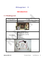
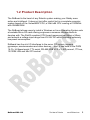
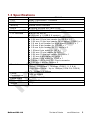
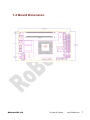
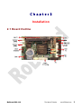
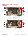
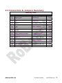
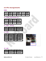
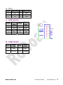
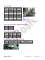
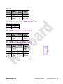
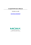
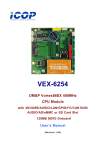
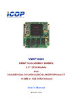
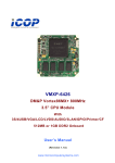
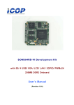
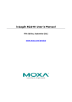
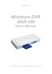
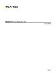
RoBoard RB‐110 Manual V1.00 The Heart of Robotics Mar 2010 DMP Electronics Inc Copyright The information in this manual is subject to change without notice for continuous improvement in the product. All rights are reserved. The manufacturer assumes no responsibility for any inaccuracies that may be contained in this document. And makes no commitment to update or to keep current the information contained in this manual. No part of this manual may be reproduced, copied, translated or transmitted, in whole or in part, in any form or by any means without the prior written permission of the DMP Electronics Inc. Copyright 2010 DMP Electronics Inc. Manual No. RoBo110-01 Ver.1.0A Mar, 20101 Trademarks Acknowledgment Vortex86DX is the registered trademark of DMP electronics Inc. Other brand names or product names appearing in this document are the properties and registered trademarks of their respective owners. All names mentioned herewith are served for identification purpose only. TableOfContents C h a p t e r 1 ............................................................................................ 4 Introduction ........................................................................ 4 1.1 Packing List.......................................................... 4 1.2 Product Description.............................................. 5 1.3 Specifications ....................................................... 6 1.4 Board Dimension ................................................. 7 C h a p t e r 2............................................................................................. 8 Installation.......................................................................... 8 2.1 Board Outline ....................................................... 8 2.2 Connectors & Pin 1 Location ............................... 9 2.3 Connectors & Jumpers Summary ...................... 10 2.4 Pin Assignments ................................................. 11 PWM.......................................................... 11 J2: COM 3 Full Duplex TTL ........................ 11 J3: USB -- 90 Deg ...................................... 11 J4: USB ..................................................... 11 J5: LAN ..................................................... 11 J7: COM1 RS-232 ...................................... 12 J8: COM2 RS-485 ...................................... 12 J11: A/D 8Ch .............................................. 13 J12: Power Connector (Board)(DC 6V-24V) 13 J16: COM4 Full Duplex TTL ....................... 13 J17: PWM initial Pull up/down switch ........ 13 J18: I2C ...................................................... 14 J19: Power Connector (PWM)(DC 6V-24V) . 14 J20: COM5 Hi-Speed serial ........................ 14 J22: COM6 Hi-Speed serial ........................ 14 2.6 Watchdog Timer ................................................. 15 C h a p t e r 3 ........................................................................................ 16 Driver Installation ............................................................ 16 A. Library, Sample and development code .............. 17 Chapter 1 Introduction 1.1 Packing List Product Name RB-100 Cable-RB-100 RoBoard RB-110 Package RoBoard RB-10 Power connector cable x 2 COM port cable x 4 (4 Pin) COM port cable x 1 (10 Pin) I 2 C cable x 1 LAN cable x 1 2x5 pin Cable x 1 The Heart of Robotics www.RoBoard.com 4 1.2 Product Description The RoBoard is the heart of any Robotic system making your Robby more active and intelligent. It does not just offer control but is a complete computer system based on the Vortex86DX CPU, a 32bit x86 CPU running at 1000MHz with 256MB RAM. The RoBoard allows users to install a Windows or Linux Operating System onto a bootable Micro-SD card offering engineers a common storage media to develop with. The RoHS compliant CPU board measures just 96mm x 50mm and accepts a voltage input range from 6V-24V DC whilst providing extremely low power consumption. RoBoard has the rich I/O interfaces to the servo, DC motors, sensors, gyroscope, accelerometers and other devices. Also, it has build-in the PWM 16 Ch, Hi-Speed serial, TTL serial, RS-485,USB V2.0 x 3, A/D convert, I2C bus, 10/100M LAN and Mini PCI socket. RoBoard RB-110 The Heart of Robotics www.RoBoard.com 5 1.3 Specifications CPU BIOS Memory ADCs Hi-Speed UART I /O Interface Connectors Resolution RB-100 DM&P Vortex86DX- 1000MHz AMI BIOS 256MB DDR2 onboard Analog Devices AD-7918 10-bit FTDI FT2232HL Hi-Speed UART Micro SD slot x1 USB port x 1 (USB 2.0 version) 2.54 mm 3-pin box header for PWM x 16 2.54 mm 10-pin box header for RS-232 x 1 2.54 mm 10 pin box header for Hi-speed (COM 6) x 1 2.0 mm 4 pin header for High speed (COM 5) x 1 2.0 mm 4-pin header for RS-485 x 1 2.0 mm 4-pin header for TTL serial x 2 1.25mm 6-pin wafer for I2C x 1 2.54 mm 16-pin header for A/D x 1 2.54 mm 10-pin box header for USB x 1 1.25 mm 4-pin wafer for LAN x 1 1.25mm 6-pin wafer for JTAG x 1 0.8mm 124-Pin Mini PCI Card connector 3.96 mm 2 pin for Power x 2 PWM : 20ns Serial : 115200bps ~ 750Kbps (COM 1, 2, 3 & 4) High Speed Serial : Up to 12Mbps (COM 5 & COM 6) I 2 C : 1Kbps ~ 3.3Mbps Power Consumption +5V @ 400mA Power Input Dimension Weight DC-in 6V to 24V 96mm X 56mm 40g RoBoard RB-110 The Heart of Robotics www.RoBoard.com 6 1.4 Board Dimension RoBoard RB-110 The Heart of Robotics www.RoBoard.com 7 Chapter2 Installation 2.1 Board Outline RoBoard RB-110 The Heart of Robotics www.RoBoard.com 8 2.2 Connectors & Pin 1 Location Connectors Pin 1 Location RoBoard RB-110 The Heart of Robotics www.RoBoard.com 9 2.3 Connectors & Jumpers Summary Summary Table J1 J2 J3 J4 J5 J6 J7 J18 J11 J12 J13 J16 J17 J8 J19 J20 J22 Description Micro-SD Slot COM 3 TTL USB USB x 2 LAN JTAG COM1 RS-485 A/D 8Ch Power Connector (Board) Mini PCI Socket COM4 TTL PWM initial pull up/down switch I2C Power Connector (PWM) COM 5 Hi-Speed (Port 1) COM 6 Hi-Speed (Port 2) RoBoard RB-110 Type of Connections Micro-SD slot Box Header,2.0mm , 4x1 USB 90 Deg Pin Header, 2,54mm, 5x2 Wafer, 1,25mm, 4x1 Wafer, 2.54mm,6x1 Pin Header, 2.54mm,5x2 Box Header,2.0mm , 4x1 Box Header, 2.54mm, 8x2 Pin Header, 3.96mm Mini PCI Type III Box Header,2.0mm , 4x1 DIP switch Wafer, 1,25mm, 6x1 Pin Header, 3.96mm Box Header,2.0mm , 4x1 Pin Header, 2.54mm,5x2 The Heart of Robotics Pin 13-pin 4-pin 4-pin 10-Pin 4-pin 6-pin 10-pin 4-pin 16-pin 2-pin 124-pin 4-pin 6-pin 2-pin 4-pin 10-pin www.RoBoard.com 10 2.4 Pin Assignments PWM Signal Name GND Pin # 1 Pin # 2 Signal Name Vxx Pin # 3 Signal Name GPxx J2: COM 3 Full Duplex TTL Signal Name GND TXD3 Pin # 1 3 Pin # 2 4 Signal Name Vxx RXD3 J3: USB -- 90 Deg Pin # 1 3 Signal Name Pin # Signal Name VCC 2 LUSBD2LUSBD2+ 4 GND J4: USB Pin # 1 3 5 7 9 Signal Name Pin # Signal Name VCC 2 VCC LUSBD04 LUSBD1LUSBD0+ 6 LUSBD1+ GND 8 GND GGND 10 GGND J5: LAN Pin # 1 3 Signal Name Pin # Signal Name LAN-TX+ 2 LAN-TXLAN-RX+ 4 LAN-RX- RoBoard RB-110 The Heart of Robotics www.RoBoard.com 11 J6: JTAG Pin # 1 3 5 Signal Name Pin # Signal Name VCC TCK TDI 2 4 6 GND TDO TMS J7: COM1 RS-232 Pin # 1 3 5 7 9 Signal Name DCD1 TXD1 GND RTS1 RI1 Pin # 2 4 6 8 10 Signal Name RXD1 DTR1 DSR1 CTS1 NC J8: COM2 RS-485 Pin # Signal Name Pin # Signal Name 1 GND 2 Vxx 3 RS-485+ 4 RS-485- RoBoard RB-110 The Heart of Robotics www.RoBoard.com 12 J11: A/D 8Ch Pin # 1 3 5 7 9 11 13 15 Signal Name AD-VIN0 AD-VIN1 AD-VIN2 AD-VIN3 AD-VIN4 AD-VIN5 AD-VIN6 AD-VIN7 Pin # Signal Name 2 4 6 8 10 12 14 16 ADGND ADGND ADGND ADGND ADGND ADGND ADGND ADGND J12: Power Connector (Board)(DC 6V-24V) Pin # Signal Name 1 2 Vxx GND J16: COM4 Full Duplex TTL Pin # 1 3 Signal Name GND TXD4 Pin # 2 4 Signal Name Vxx RXD4 J17: PWM initial Pull up/down switch Pin # 1 Signal Name PWM init Pull UP RoBoard RB-110 Pin # 2 Signal Name PWM init Pull Down The Heart of Robotics www.RoBoard.com 13 J18: I 2 C Pin # 1 3 5 Signal Name Vcc SCL Reset Pin # 2 4 6 Signal Name GND SDA 3.3V out J19: Power Connector (PWM)(DC 6V-24V) Pin # Signal Name 1 2 Vxx GND J20: COM5 Hi-Speed serial (Port 1) Pin # 1 3 Signal Name GND TXD5 Pin # 2 4 Signal Name Vxx RXD5 J22: COM6 Hi-Speed serial (Port 2) Pin # 1 3 5 7 9 Signal Name DCD6 TXD6 GND RTS6 RI6 RoBoard RB-110 Pin # 2 4 6 8 10 Signal Name RXD6 DTR6 DSR6 CTS6 TXDEN6 The Heart of Robotics www.RoBoard.com 14 2.6 Watchdog Timer There are two watchdog timers in Vortex86DX CPU. One is compatible with M6117D watchdog timer and the other is new. The M6117D compatible watchdog timer is called WDT0 and new one is called WDT1. We also provide DOS, Linux and WinCE example for your reference. For more technical support, please visit: http://www.dmp.com.tw/tech or download the PDF file: http://www.dmp.com.tw/tech/vortex86dx/ RoBoard RB-110 The Heart of Robotics www.RoBoard.com 15 Chapter 3 Driver Installation VGA The Vortex86DX processor also use external Display chip ““Volari™ Z9s” which is an ultra low powered graphics chipset with total power consumption at around 1-1.5 W. It is capable in providing VGA display output up to 1600x1200. With DVO interface, developers could easily connect flat Panel to support TFT and LVDS output. LAN The Vortex86DX processor also integrated 10/100Mbps Ethernet controller that supports both 10/100BASE-T and allows direct connection to your 10/100Mbps Ethernet based Local Area Network for full interaction with local servers, wide area networks such as the Internet. AUDIO CM119 is a highly integrated single chip USB audio controller specifically for VoIP (Voice over internet protocol) application. All essential analog modules are embedded in CM119, including dual DAC and earphone driver, ADC, microphone booster, PLL, regulator, and USB transceiver. The RB-100 provides the VGA and LAN drivers for Windows XP, Windows CE 5.0 and Windows Embedded CE 6.0R2 and Windows Embedded Standard (XPe). Please get from official website: http://www.roboard.com The RB-100 also supports most of the popular Linux distributions, for more detail information, please visit DMP official website: http://www.dmp.com.tw/tech/vortex86dx/ RoBoard RB-110 The Heart of Robotics www.RoBoard.com 16 A. Library, Sample and development code The RB-100 provides the Library, sample and development code. Please download from official website: http://www.roboard.com RoBoard RB-110 The Heart of Robotics www.RoBoard.com 17 Warranty This product is warranted to be in good working order for a period of one year from the date of purchase. Should this product fail to be in good working order at any time during this period, we will, at our option, replace or repair it at no additional charge except as set forth in the following terms. This warranty does not apply to products damaged by misuse, modifications, accident or disaster. Vendor assumes no liability for any damages, lost profits, lost savings or any other incidental or consequential damage resulting from the use, misuse of, originality to use this product. Vendor will not be liable for any claim made by any other related party. Return authorization must be obtained from the vendor before returned merchandise will be accepted. Authorization can be obtained by calling or faxing the vendor and requesting a Return Merchandise Authorization (RMA) number. Returned goods should always be accompanied by a clear problem description. RoBoard RB-110 The Heart of Robotics www.RoBoard.com 18