1
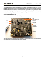
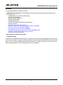
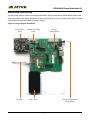
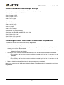
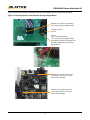
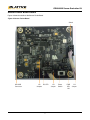
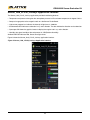
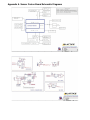
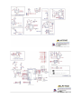
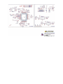
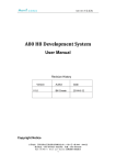
iCE40LM4K Sensor Evaluation Kit User’s Guide January 2014 EB83_01.0 iCE40LM4K Sensor Evaluation Kit Introduction Thank you for choosing the Lattice iCE40LM4K Sensor Evaluation Kit. This guide describes how to begin using the iCE40LM4K Sensor Evaluation Kit, an easy-to-use platform for rapidly prototyping system control designs using an iCE40LM FPGA. Along with the evaluation board and accessories, this kit includes a pre-loaded demo that allows communication between the iCE40LM4k Sensor Evaluation Kit and a Qualcomm Snapdragon APQ8060A board (not included in the package and may be purchased from Intrinsyc). The content of this user’s guide includes an overview of the features of the board and a step by step guide to using the iCE40LM4K Sensor Evaluation Kit with the Qualcomm Snapdragon APQ8060A. Figure 1. iCE40LM4K Daughter Card Humidity and Temperature Hall RGB Ambient Light Proximity IR Tx Barometer IR Rx Accelerometer Gyroscope iCE40LM4K Compass CAUTION: Static electricity can severely shorten the lifespan of electronic components. Be careful when handling the iCE40LM4K Sensor Evaluation Kit to prevent damage from ESD. 2 iCE40LM4K Sensor Evaluation Kit Features The iCE40LM4K Sensor Evaluation Kit includes: • iCE40LM4K Evaluation Board – The ICE40LM4k Evaluation Board features the following on-board components and circuits: – iCE40LM4K Device in the 25 WLCSP Package – High-Current LED Output – Infrared Transmit and Receive – Barcode LED/Emulation – Configuration SPI Flash – On-board FT2232HL for USB Programming/Interface – Numerous Sensors – Proximity Sensor (AMS-TAOS TMD27711) – RGB Color, Infrared, and Temperature Sensors (Maxim MAX44006) – Barometric Pressure Sensor (Bosch BMP085) – Accelerometer and Gyro (ST Micro LSM330DLC) – Magnetometer/Compass/Accelerometer (ST Micro LSM303DLHCTR) – Humidity and Temperature Sensor (Sensirion SHT20) – Hall Sensor (Rohm BU52051NVX) • SMA Connector for External Clock Input • On-Board Oscillator In addition to the iCE40LM4K Evaluation Board, an adapter board for connection to Dragon Board and a connector cable are also included. This secondary PCB connected by a cable allows the iCE40LM4k Sensor Evaluation Kit to interface with a Qualcomm 8060A Dragon Board (Dragon Board is available separately and not sold by Lattice). When connected properly, a sensor hub demonstration can be conducted. 3 iCE40LM4K Sensor Evaluation Kit Sensor Hub Demo Setup The demo setup consists of the Intrinsyc Dragon Board Gen2, Sensor Fusion Board, and flexible connecting cable. To set up the Sensor Hub demo, connect the Sensor Fusion Board to the Intrinsyc Adapter board which is placed on the Intrinsyc Dragon Board Gen2 as shown in Figure 2 Figure 2. Intrinsyc Dragon Board Gen2 Sensor Fusion Board OTG Mini Flexible Connecting Cable Intrinsyc Dragon Board Touch Screen Intrinsyc DragonBoard Power Supply 4 iCE40LM4K Sensor Evaluation Kit Sensor Fusion Board Default Jumper Settings This section provides the details of the Sensor Fusion Board jumper settings: • Set J2 jumper on OSC mode in EXT CLK. • Set J4 jumper on BAR. • Set J5 jumper on HALL. • Do not set J7 jumper. • Set J8 jumper. • Do not set J10 jumper. • Do no set J11 jumper. • Set J12 jumper. • Do not set J15 jumper. • Set both the J16 jumpers vertically. • Set jumper on IDD-CORE and IDD-TOP (J18 & J19). • Set VCCIO0 (J22) to 1.8V. • Set VCCIO2 (J17) set to 3.3V. • Set J20 jumper on USB mode. Connecting the Sensor Fusion Board to the Intrinsyc Dragon Board To connect the Sensor Fusion Board to the Intrinsyc Dragon Board 1. Power-off the Intrinsyc Dragon Board. 2. Connect the Intrinsyc Dragon Board end of the processor configuration cable to the Intrinsyc Adapter board mounted on the Intrinsyc Dragon Board. i. The marked pin of the cable connector should be connected to pin 1 of the connector on the Intrinsyc Adapter board near the white dot. 3. Connect the smaller connector on other end of the cable to the J21 connector of the Sensor Fusion Board. i. The marked pin of the cable connector should be connected to pin 1 of the J21 connector near the white dot. 4. Connect the larger connector on the other end of the cable to the J13 connector of the Sensor Fusion Board. i. The marked pin of the cable connector should be connected to pin 1 of the J21 connector near the white dot. 5. Power-on the Intrinsyc Dragon Board after the above connections are completed. Note: Do not connect the mini USB power cable to the Sensor Fusion Board when it is connected to the Intrinsyc Dragon Board. 5 iCE40LM4K Sensor Evaluation Kit Figure 3 shows the connections between the Sensor Fusion Board and the Intrinsyc Dragon Board. Figure 3. Connecting Sensor Fusion Board to Intrinsyc Dragon Board Marked end of cable connected to pin1 of the Intrinsyc Adapter board Jumper to be set at 3.3V 5V fly wire (supplied) to be connected between +5V on the Intrinsyc Adapter board (plugged in) and the C1300 right side terminal (soldered) on the Intrinsyc Dragon Board Marked end of smaller connector, connected to pin1 of J21 on the Sensor Fusion Board Marked end of larger connector, connected to pin1 of J13 on the Sensor Fusion Board 6 iCE40LM4K Sensor Evaluation Kit Sensor Fusion Board Details Figure 4 shows the details of the Sensor Fusion Board. Figure 4. Sensor Fusion Board Switch Mini USB Connector J16 D3 LED Jumpers 7 J21 Jumper Power Switch PWR SEL J20 J13 Jumper iCE40LM4K Sensor Evaluation Kit Flashing System Image and Boot Image to Intrinsyc Dragon Board Note that this procedure is not required if the Intrinsyc Dragon Board has already been flashed with the system image and boot image (cd Lightning_Demos_Drop_WITH_APK_INSTALL/Dragonboard_boot_images/). To flash the system image and boot image to the Intrinsyc Dragon Board: 1. Connect the Intrinsyc Dragon Board USB port to your host system through the OTG (mini-USB). i. Download and install android-sdk. Android-sdk for Linux and Windows environment at http://developer.android.com/sdk/index.html. Set <Installation path>/android_sdk/platform-tools/ to the PATH variable. 2. Run the command below in the terminal/command prompt. #sudo –s Note: This command is applicable only for Linux machines. For Windows machine administrative permission is necessary. 3. Reboot the Intrinsyc Dragon Board in fastboot mode. i. Keep Button Vol / Zoom + pressed on the Intrinsyc Dragon Board during restart. If the board is already On in adb mode, use the command below for fastboot mode #adb reboot bootloader ii. When the Intrinsyc Dragon Board is in FASTBOOT mode, a white screen comes on with only Intrinsyc name displayed on it. iii. Execute the command below in the terminal/command prompt to list the fastboot device number and its name. #fastboot devices The board is now ready to be flashed with boot.img. 4. Enter the command below to flash system image. #fastboot flash system system.img If flashing is successful, OKAY and Finished comments are displayed on the terminal. 5. Enter the command below to flash boot.img #fastboot flash boot boot.img If flashing is successful, OKAY and Finished comments are displayed on the terminal. 6. Enter the command below reboot the board for current boot.img. #fastboot reboot 7. After reboot, go to Settings > Developer options > Stay awake. 8 iCE40LM4K Sensor Evaluation Kit Installing Sensor Hub apk to Android To flash the system image and boot image to the Intrinsyc Dragon Board: 1. Connect the Intrinsyc Dragon Board USB port to your host system through the OTG (mini-USB). 2. Run the command below in the terminal/command prompt. #sudo –s Note: This command is applicable only for Linux machines. For Windows machine administrative permission is necessary. 3. Use below commands on the terminal to establish and verify 'adb' connection. #adb kill-server #adb start-server #adb devices If the connection is successful, the device id is displayed on the terminal. 4. Run the command below to install the Sensor Hub apk to the Intrinsyc Dragon Board. #cd Lightning_Demos_Drop_WITH_APK_INSTALL/Sensor_Hub_Demo_Quick_Strart /Android_Apllication Note: This step should be performed only if not currently in the Lightning_Demos_Drop_WITH_APK_INSTALL/Sensor_Hub_Demo_Quick_start/Android_Apllication/ folder #adb install Sensor_Hub_Demo.apk Demo Procedure To execute the demo: 1. Restart Intrinsyc Dragon Board by removing and re-plugging in the power supply, with the Sensor Fusion Board connected to it. When connecting the Sensor Fusion Board to Intrinsyc Dragon Board, make sure that jumper J20 on the Sensor Fusion Board is in DRG mode. 2. Wait for Android boot sequence to complete and the home screen to appear. 3. Unlock the screen. Go to the Android application menu and open Sensor_Hub_LP3.5k_Intrinsyc. 4. Wait for the Processor Configuration to be completed. This is indicated by the lighting of the D3 LED on the Sensor Fusion board. 5. The sensor data is displayed on the Sensor_Hub_LP3.5k_Intrinsyc application. 9 iCE40LM4K Sensor Evaluation Kit Sensor_Hub_LP3.5k_Intrinsyc Application Features The Sensor_Hub_LP3.5k_Intrinsyc application provides the following features: • Temperature and pressure data gives the atmosphere pressure in kPa and room temperature in degree Celcius. • Compass image points to the magnetic north w.r.t the Sensor Fusion Board. • Light sensor progress bar indicates the intensity of light form 0 – 4000 lux. • Accelerometer GUI indicates acceleration in x,y and z direction. The dots indicate the direction and acceleration. • Gyroscope GUI shows the graphical meter to display the angular rate in x,y and z direction. • Humidity data gives humidity of the environment in %RH(Relative Humidity). Ambient RGB GUI indicates Red, Green, Blue light values. Figure 5 shows the Sensor_Hub_LP3.5k_Intrinsyc application interface. Figure 5. Sensor_Hub_LP3.5k_Intrinsyc Application Interface 10 iCE40LM4K Sensor Evaluation Kit Troubleshooting If the Android application does not respond, perform the following procedure: 1. Close the Sensor_Hub_LP3.5k_intrinsyc process running in background. In the Android menu, go to Settings > Applications > Manage Applications > Sensor_Hub_LP3.5k_intrinsyc Force Stop 2. Restart the Intrinsyc Dragon Board. 3. Open the Sensor_Hub application from Android menu and application is ready to receive all sensor’s data. 4. If the android application crashes while being opened, it means that the library file has not been copied. Run the command below to install the Sensor Hub apk to the Intrinsyc Dragon Board. #cd Lightning_Demos_Drop_WITH_APK_INSTALL/Sensor_Hub_Demo_Quick_Strart /Android_Apllication Note: This step should be performed only if not currently in the Lightning_Demos_Drop_WITH_APK_INSTALL/Sensor_Hub_Demo_Quick_start/Android_Apllication/ folder #adb install Sensor_Hub_Demo.apk 11 iCE40LM4K Sensor Evaluation Kit Technical Support Assistance e-mail: [email protected] Internet: www.latticesemi.com Revision History Date Version January 2014 01.0 Change Summary Initial release. © 2014 Lattice Semiconductor Corp. All Lattice trademarks, registered trademarks, patents, and disclaimers are as listed at www.latticesemi.com/legal. All other brand or product names are trademarks or registered trademarks of their respective holders. The specifications and information herein are subject to change without notice. 12 Appendix A. Sensor Fusion Board Schematic Diagrams