1
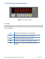
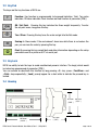
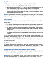
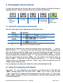
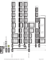
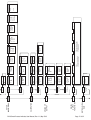
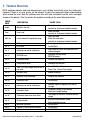
BX18
Smart Process Indicator
User Manual
SAFETY INSTRUCTIONS
CAUTION! READ THIS MANUAL BEFORE OPERATING OR SERVICING THIS EQUIPMENT.
FOLLOW THESE INSTRUCTIONS CAREFULLY. SAVE THIS MANUAL FOR FUTURE
REFERENCE. DO NOT ALLOW UNTRAINED PERSONNEL TO OPERATE, CLEAN, INSPECT,
MAINTAIN, SERVICE, OR TAMPER WITH THİS EQUIPMENT. ALWAYS DISCONNECT THIS
EQUIPMENT FROM THE POWER SOURCE BEFORE CLEANING OR PERFORMING
MAINTENANCE. CALL BAYKON ENGINEERING FOR PARTS, INFORMATION, AND SERVICE.
WARNING! ONLY PERMIT QUALIFIED PERSONNEL TO SERVICE THIS EQUIPMENT.
EXERCISE CARE WHEN MAKING CHECKS, TESTS AND ADJUSTMENTS THAT MUST BE
MADE WITH POWER ON. FAILING TO OBSERVE THESE PRECAUTIONS CAN RESULT IN
BODILY HARM.
WARNING! FOR CONTINUED PROTECTION AGAINST SHOCK HAZARD CONNECT TO
PROPERLY GROUNDED OUTLET ONLY. DO NOT REMOVE THE GROUND PRONG.
WARNING! DISCONNECT ALL POWER TO THIS UNIT BEFORE REMOVING ANY
CONNECTION, OPENING THE ENCLOSURE OR SERVICING.
WARNING! BEFORE CONNECTING/DISCONNECTING ANY INTERNAL ELECTRONIC
COMPONENTS OR INTERCONNECTING WIRING BETWEEN ELECTRONIC EQUIPMENT
ALWAYS REMOVE POWER AND WAIT AT LEAST THIRTY (30) SECONDS BEFORE ANY
CONNECTIONS OR DISCONNECTIONS ARE MADE. FAILURE TO OBSERVE THESE
PRECAUTIONS COULD RESULT IN DAMAGE TO OR DESTRUCTION OF THE EQUIPMENT
OR BODILY HARM.
CAUTION! OBSERVE PRECAUTIONS FOR HANDLING ELECTROSTATIC SENSITIVE
DEVICES.
RIGHTS AND LIABILITIES
All rights reserved.
No part of this publication may be reproduced, stored in a retrieval system, or transmitted in any form or by any
means, mechanical, photocopying, recording, or otherwise, without the prior written permission of BAYKON A.S.
No patent liability is assumed with respect to the use of the information contained herein. While every precaution
has been taken in the preparation of this book, BAYKON assumes no responsibility for errors or omissions. Neither
is any liability assumed for damages resulting from the use of the information contained herein.
The information herein is believed to be both accurate and reliable. BAYKON, however, would be obliged to be
informed if any errors occur. BAYKON cannot accept any liability for direct or indirect damages resulting from the
use of this manual.
BAYKON reserves the right to revise this manual and alter its content without notification at any time.
Neither BAYKON nor its affiliates shall be liable to the purchaser of this product or third parties for damages,
losses, costs, or expenses incurred by purchaser or third parties as a result of: accident, misuse, or abuse of this
product or unauthorized modifications, repairs, or alterations to this product, or failure to strictly comply with
BAYKON operating and maintenance instructions.
BAYKON shall not be liable against any damages or problems arising from the use of any options or any
consumable products other than those designated as Original BAYKON Products.
NOTICE: The contents of this manual are subject to change without notice.
Copyright © 2012 by BAYKON A.S. Istanbul, Turkey
Contents:
1. TECHNICAL SPECIFICATIONS ..................................................................................... 2
2. THE FRONT VIEW AND KEY FUNCTIONS ....................................................................... 3
2.1
2.2
2.3
2.4
2.5
2.6
Display
Key Pad
Key Lock
Housing
Accessories supplied with the instrument
Accessories sold separately
3
4
4
4
5
5
3. INSTALLATION ....................................................................................................... 6
3.1
3.2
Recommendations
How to install the instrument and Scale ?
6
6
Step 1. Mechanical Installation ......................................................................................................... 7
Step 2. Load Cell Connection ............................................................................................................ 7
Step 3. Power Supply Connection and Grounding.............................................................................. 7
Step 4. Energize the instrument ........................................................................................................ 8
Step 5. Set the calibration switch to programming and calibration .................................................... 8
Step 6. Programming ....................................................................................................................... 9
Step 7. Calibration ............................................................................................................................ 9
Step 8. Testing the scale performance.............................................................................................. 9
Step 9. Bring the DIP switch to up position to unlock the scale adjustment ....................................... 9
Step 10. Peripheral related parameters programming, if any .......................................................... 10
Step 11. Peripheral connections ..................................................................................................... 10
Step 12. Peripheral connections testing .......................................................................................... 14
4. PROGRAMMING AND CALIBRATION ........................................................................... 15
4.1
4.2
4.3
Entering the Programming and Calibration
Exiting the Programming and Calibration
Fast Access to the Calibration
15
15
21
5. ANALOGUE ......................................................................................................... 26
6. RS232C AND RS485 DATA OUTPUTS .................................................................... 27
6.1
6.2
6.3
6.4
Continuous Data Output
Fast Continuous Data Output
Print Mode
BSI Data Structure
27
28
28
29
7. TROUBLE SHOOTING ............................................................................................. 30
8. FREQUENTLY ASKED QUESTIONS ............................................................................. 31
DECLARATION OF CONFORMITY ................................................................................... 32
BX18 Smart Process Indicator, User Manual, Rev. 1.1, May 2013
Page 1 of 32
1. TECHNICAL SPECIFICATIONS
A/D Converter:
A/D converter type:
24 bit Delta-Sigma radiometric with integral analog and digital filters
Conversion rate:
Up to 1600 measurement values per second
Input sensitivity:
0.1 μV/e (non approved)
Analog input range:
0 mV to +18 mV ( unipolar ) ;
Internal resolution:
up to 16 000 000
- 18 mV to +18 mV ( bipolar )
External Resolution:
Display resolution
up to 999 999 increment
Scale Calibration and Functions:
Calibration:
Calibration is performed with or without test weights ( eCal )
Digital filter:
10 steps programmable adaptive filter
Taring, zeroing, auto zero tracking, motion detection, auto zero at power up, net
indication at power on, increased resolution
Weighing functions:
Linearity:
Within 0.0015% FS, ≤ 2 ppm/°C
Load cells:
Excitation:
5 VDC max. 300 mA
Number of load cells:
Up to 8 load cells 350 Ω or 18 load cells 1100 Ω in parallel
4- or 6-wire technique.
Cable length: maximum 250 m/mm² for 6-wire connection
Connection:
RS 485
RS 232
Communication:
Baudrate
1200 to 115200 baudrate, 8N1 / 7E1 / 7O1
Response speed:
Up to 4 ms. response delay after read/write commands
Baudrate
1200 to 115200 baudrate, 8N1 / 7E1 / 7O1
Response speed:
Up to 4 ms. response delay after read/write commands
Max Stations:
Up to 31 stations per segment
Analogue Output:
Voltage output:
0-5 VDC, 0-10 VDC
Current output:
4-20mA, 0-20mA
D/A Converter:
16 bit
Max. cable length:
300 meter
Max. load resistance:
500 Ω
(current output )
Digital Inputs and Outputs:
Digital Inputs
4 optoisolated digital input, 12 to 28 VDC, 10mA
Digital Outputs
6 free relay contact, 250 VAC or 30 VDC , 1A
DC Power supply:
12 to 28 VDC max. 300 mA
Environment and Enclosure:
Operation temp.:
-10 °C to +40 °C; 85% RH max, non-condensing
Enclosure
Polycarbonate, DIN rail type
Protection
Front panel IP65
BX18 Smart Process Indicator, User Manual, Rev. 1.1, May 2013
Page 2 of 32
2. THE FRONT VIEW AND KEY FUNCTIONS
Figure 2-1 - Front panel view of BX18
2.1 Display
The weight display of BX18 is seven segments LED. At the right side of the display there are three
LED’s for indicating the net, gross and the unit ( standard kg ). The meanings of the announcement
LED’s on the display are:
Gross
Announces the indicated value is the gross weight.
Net
Announces the indicated value is the net weight.
Announces the weight is in the center of zero.
Announces the weight value on the display is unstable.
Units
g, kg, t, lb, klb, N, kN units are located on the right of the
display.
BX18 Smart Process Indicator, User Manual, Rev. 1.1, May 2013
Page 3 of 32
2.2 Key Pad
The keys and the key functions of BX18 are:
Function: Key function is programmable to Increased Indication, Total, Tare value
indication, CN value indication, Peak function and Hold function at parameter [ 116 ].
GN / Set Point: Pressing this key indicates the Gross weight temporarily. To enter
the set point menu, long press this key.
Tare / Clear: Pressing this key tares the scale and get into the Net mode.
Zeroing: In Gross mode, if the scale doesn’t show zero while there is no load on the
pan, you can zero the scale by pressing this key.
Print: By pressing this key weight data and other information depending on the setup
parameters sent to a printer or a PC via serial port.
2.3 Key Lock
BX18 has ability to lock the keys to avoid unauthorized person’s interfere. The key(s) which would
be locked are programmed at parameter [ 115 ].
You can activate or deactivate this function by long pressing <F> key, press <Tare/Clear> and
<Print> keys sequentially. [ Lock ] prompt appear for a short while to indicate the pressed key is
locked.
2.4 Housing
67,5 mm 89,7 mm
( 2,66" ) ( 3,53" )
107,6 mm
( 34,24" )
BX18 Smart Process Indicator, User Manual, Rev. 1.1, May 2013
62,2 mm
( 2,45" )
Page 4 of 32
2.5 Accessories supplied with the instrument
The following accessories are supplied together with the BX18 instrument. If any part is missed,
please contact to your supplier.
Pieces
3-pos and 5,08 mm pitch green plug for Power supply
1
7-pos and 3,81 mm pitch black plug for load cell cable
and Digital outputs
2
3-pos and 3,81 mm pitch green plug for RS 232C and RS 485
2
5-pos and 3,81 mm pitch green plug for Analogue output
and Digital inputs
2
User Manual
1
Installation CD
(IndFace1X setup and technical documents)
1
Table 2.1 - Accessories supplied with instrument
2.6
Accessories sold separately
The following accessories can be supplied from BAYKON.
RS-232C cable for PC connection
( 3 meter )
√
Junction box for load cell connection
Refer to junction box catalog
Open end load cell cable
6 wire ( 0.22 cm2 each )
Maximum 200 meter length
Table 2.2 - Accessories supplied separate
BX18 Smart Process Indicator, User Manual, Rev. 1.1, May 2013
Page 5 of 32
3. INSTALLATION
PRECAUTION: Please read this section carefully before installation of the instrument. Applying the
recommendations in this section will increase your system reliability and long term performance.
3.1 Recommendations
Control Cabinet Design
Warning: Please care the following warnings for designing the control cabinet which will increase
your system reliability.
The control cabinet should be designed so that Analog Digitizer can operate safely. The panel
should be placed clean area, not getting direct sun light if possible, with a temperature between -10
ºC and +40 ºC, humidity not exceeding 85% non-condensing. All external cables should be installed
safely to avoid mechanical damages.
BX18 instrument is very low level signal measuring instrument. To avoid electrical noise, BX18
should be separated from the equipments that produce electrical noise. Preferable use metal
cabinet against radio frequency interference and the cabinet shall be connected to ground against
the electromagnetic disturbances. Load cell cable trays must be separated from others, if possible.
If there are noise-generating equipments such as heavy load switches, motor control equipments,
inductive loads etc., please be careful against the EMC interference in the cabinet. If possible
protect BX18 instrument with the faraday cage or install them in separate section or install them far
a way from this kind of equipments. Connect parallel reverse diodes to the DC inductive loads like
relays, solenoids etc. to minimize voltage peaks on the DC power lines.
Cabling
All cables coming to the control cabinet shall be shielded. Please use separate cable tray for these
low signal level cables. Distance from load cell cables, interface cables and DC power supply cables
to power line cables shall be minimum 50 cm.
Warning: Please always remember that BX18 instrument is very low voltage measuring instrument.
Your control cabinet design and proper installation increases reliability and performance of the
instrument. Please do not forget that the instrument must be powered off before inserting or
removing any peripheral connector.
3.2 How to install the instrument and Scale ?
Please folow the installation and commissioning steps described below carefully to prevent
unwanted results after installation.
BX18 Smart Process Indicator, User Manual, Rev. 1.1, May 2013
Page 6 of 32
Step 1. Mechanical Installation
Take care to the housing dimensions given in the Page 4. Install the indicator in the cabinet. Be
sure, all mechanical installation of your mechanical system and panel are finalizing before starting
the next step.
Step 2. Load Cell Connection
Warning: After load cell connection to the instrument, the welding on the mechanical constriction is
not recommended. Disconnect all connectors from indicator before welding on the mechanical
hardware.
Load cell connection detail is shown in Figure 3-1. In 4-wire installations the sense and excitation
pins with the same polarity should be short circuited at the connector side. If you have junction
box, use 6 wire cable between BX18 and the junction box, and short circuit these pins at junction
box for better performance.
4 wire LC connection
6 wire LC connection
Figure 3-1 - Load cell connections
Warning: Always connect Sense pins to Excitation pins for 4 wire connection. Non-connected
sense pins may cause the wrong Excitation voltage measurement and create an accuracy problem.
Warning: Connect the load cell cable shield to the reference ground or shield pin of the load cell
connector.
Step 3. Power Supply Connection and Grounding
The quality of the instrument’s ground will determine the accuracy and the safety of your measuring
system. A proper ground connection is needed to minimize extraneous electrical noise affects on
the measurement. A poor ground can result in an unsafe and unstable operation. It is important that
the instrument should not share power lines with noise-generating parts such as heavy load
switching relays, motor control equipments, inductive loads, etc. If the condition of the power line in
the plant is poor, prepare a special power line and grounding.
Power supply voltage of the instrument shall be between 12 VDC and 28 VDC. The pin configuration
of the 24 VDC power supply connector located left- bottom of the instrument is shown in figure
below. Be sure, the power supply is switched of before connection.
BX18 Smart Process Indicator, User Manual, Rev. 1.1, May 2013
Page 7 of 32
The pin layout of the
24 VDC connector of
BX18
( Top view )
24V 0V
Figure 3-2 - The pin layout of 24VDC connector
Warning: Before interfering the instrument, turn off the power and wait at least for 30 seconds.
Warning: Connect the grounding
pin to the reference ground.
Step 4. Energize the instrument
Check the mechanical installation, grounding, load cell connection and power supply connection to
be sure the correct electrical installation before energizing the instrument. If before steps are done
properly energize the instrument.
Step 5. Set the calibration switch to programming and calibration
Warning : If the scale is sealed before, call the authorized person before interfaring the scale.
If any, a set-up DIP switch is located under the blind cover as shown in the figure below and its
position should be “ON” ( downward ) to change the metrological related parameters including
calibration. If there is not set-up DIP switch on the instrument for industrial usage, its position is
always ON.
DIP Switch Description
1
Calib SW
2
Reserve
Figure 3-3 - The location of calibration DIP switch
BX18 Smart Process Indicator, User Manual, Rev. 1.1, May 2013
Page 8 of 32
Step 6. Programming
You will program the instrument according to your application in this step. Adjust;
• Interface parameters in block [ 00- ] RS232 and [ 01- ] RS485 serial ports,
• Configuration parameters in block [ 1-- ] for scale functions related with application like
saving tare before power off and restart in Net mode and digital I/O related entries.
• Set up parameters to set up the scale in block [ 2-- ] like zeroing range. Please remember
these parameter values are restricted for scale usage in trade. You have to enter the scale
capacity and devision values in this block.
Warning: The programming and parameter descriptions are referred in Page 15. We recommend
you to save these parameters before next step against to lost the adjustments in this step if
calibration can not performed somehow.
Step 7. Calibration
You will calibrate the scale after programming the parameters. You may follow one the calibration
methods below.
• eCal Electronic calibration without test weight need viaIndFace1x or fieldbus. Refer to Page 19
• Full calibration via keys on the instrument by using test weight. Refer to Page 19.
• Zero adjustment and span adjustment in sequence via keys or fieldbus. Span calibration is
needed test weight. You may save the zero adjustment before starting span adjustment.
Refer to Page 21.
• Zero adjustment and span adjustment under load in sequence via keys if the scale cannot be
emptied when the span adjustment is performed. Need test weight for span calibration. Refer
to Page 22.
You may access to the calibration menu from operation menu by following the description in fast
access to the calibration section ( Page 21 ). After the calibration go back to the operation menu
after saving adjustment ( Refer to Page 15 )
Remember: You may use parameter 905 to follow the load cell output voltage on loading, if you can
not perform the calibration.
Step 8. Testing the scale performance
You have to check your scale performance by testing the scale eccentricity, scale linearity at
loading until maximum loading value and unloading, repeatability etc. before using it. If testing
results are not in your limits recheck the steps above and your hardware to find the error source.
Step 9. Bring the DIP switch to up position to unlock the scale adjustment
If the DIP switch is bring to the downward position for programming, push it to the upward position
to lock the scale adjustment against interfaring the un-autorized persons in to the scale. If the scale
is used in non-trade industrial weighing, this step is not must.
Warning: If the scale is used in trade, the scale should be sealed after bringing the DIP switch to
the upward position sealed before. Call the authorized person for sealing the scale, if need be.
BX18 Smart Process Indicator, User Manual, Rev. 1.1, May 2013
Page 9 of 32
Step 10. Peripheral related parameters programming, if any
If you will connect any peripheral to the instrument, you have to set the related parameters up.
Refer to Page 10 for digital input/output and Page 22 for analog output programming.
Step 11. Peripheral connections
If you will make any peripheral connection like digital input, digital output, RS232 or RS485
switched off the power supply and connect you peripheral as described below and in the related
section of this manual. You will find detailed description on the peripheral connection and
interfacing details in the BX18 technical manual.
Important : Powered off the instrument before any connector installing to the instrument.
Digital Input Connection
BX18 inputs which are independently programmable for zeroing, taring, clear, print, key lock, peak,
hold, and as a fieldbus input port. If the input is programmed as a fieldbus input port, the input
status is transferred to the PLC by fieldbus command.
Inputs are 12~28 VDC,10 mA.
Zero or Tare functions :
Peak function :
Hold function :
Inputs connection diagram is shown in Figure 3-4.
Figure 3-4 - BX18 Inputs connection
diagram
BX18 Smart Process Indicator, User Manual, Rev. 1.1, May 2013
Page 10 of 32
Digital Output Connection
BX18 instrument’s digital outputs are can be used as a standard, threshold and window. Threshold
and window outputs are also programmable positive or negative polarity. Digital outputs of BX18 are
also programmable as a fieldbus port to control them with a fieldbus commands. Refer to parameter
[ 130 ] and [ 70- ].
Outputs are 250 VAC or 30 VDC, 1A. Outputs connection diagram is shown in Figure 3-5.
Figure 3-5 - BX18 Outputs connection diagram
Standard Output:
Only one set point value is entered.
The output state is forced active high
when the weight is higher than SP1,
else the output is passive.
Refer to parameter [ 130 ].
Threshold Output:
2 set point values are entered. SP1 is
the point that the output goes active
when the weight increased from
SP1_H. SP1_L is the point that the
output drops to passive state when
the weight decreased to SP1_L.
Inverse function is available.
Refer to parameter [ 7-- ].
BX18 Smart Process Indicator, User Manual, Rev. 1.1, May 2013
Page 11 of 32
Window Output:
2 set point values are entered. The
output is active when the weight is
between SP1_L and SP1_H.
Inverse function is available.
Refer to parameter [ 7-- ].
RS 232C Connection
RS 232C port usage and specifications are shown in the table below.
Usage
Interfacing with PC or PLC, remote display connection,
programming via IndFace1X
Data
formats
Continuous, Fast Continuous, Printer Format, BSI Protocol,
Modbus-RTU High-Low, Modbus-RTU Low-High
(Parameter [ 000 ])
Baud rate
1200 / 2400 / 4800 / 9600 (Default) / 19200 / 38400 / 57600 / 115200 bps
(Parameter [ 001 ])
Length
and parity
Start/
Stop bits
8 bit no parity (Default), 7 bit odd, 7 bit even
(Parameter [ 004 ])
1 start bit and 1 stop bit
RS 232C serial connection is done with three wire as indicated below in Figure 3-6.
Figure 3-6 - RS 232C serial interface connections
Warning: Connecting the shield to the reference ground will protect your weighing system against
EMC disturbances.
BX18 Smart Process Indicator, User Manual, Rev. 1.1, May 2013
Page 12 of 32
RS 485 and Modbus-RTU Connection
RS 485 port usage and specifications are shown in the table below.
Usage
Interfacing with PC or PLC, remote display,
programming via Indface,
Data
formats
Continuous, Fast Continuous, Printer Format, BSI Protocol,
Modbus-RTU High-Low, Modbus-RTU Low-High
(Parameter [ 010 ])
Baud rate
1200 / 2400 / 4800 / 9600 (Default) / 19200 / 38400 / 57600 / 115200 bps
(Parameter [ 011 ])
Length
and parity
Start /
Stop bits
8 bit no parity (Default), 7 bit odd, 7 bit even
(Parameter [ 014 ])
1 start bit and 1 stop bit
RS 485 serial connection is done with three wire as indicated below in Figure 3-7. Line termination
resistors ( 110 ohm ) are needed both ends of the RS 485 line.
Figure 3-7 - RS485 serial interface connections
Warning: Connect the shield to the reference ground.
Warning: Disconnect IndFace1X PC software before starting Modbus-RTU interfacing.
Analogue Output Connection
BX18 is programmable to 4 – 20 mA, 0 – 20 mA, 0 – 5 V or 0 – 10 V analogue output types.
Analogue connections are done as indicated below in Figure 3-8 and Figure 3-9.
Figure 3-8 – BX18 Voltage output connections
BX18 Smart Process Indicator, User Manual, Rev. 1.1, May 2013
Page 13 of 32
Figure 3-9 - BX18 Current output connections
Step 12. Peripheral connections testing
Test your peripheral connections. You may change the related parameters in your testing for better
performance, if need be.
You may use also main parameter group [ 9-- ] for RS232, RS485, and digital In / Out testing.
BX18 Smart Process Indicator, User Manual, Rev. 1.1, May 2013
Page 14 of 32
4. PROGRAMMING AND CALIBRATION
The signs those take place on the lower right corner of the keys indicate the function of the keys in
programming menu. The basic meanings of these keys are given the table below.
• Return to main
block
• Exit without
saving
Advancing next
parameter
Select the digit will Changing parameter • Go to the next
be changed
value or increasing
parameter
the blanking digit • Enter
• Save and Exit
4.1 Entering the Programming and Calibration
Follow the steps below to enter programming and calibration menus.
Display
Operation
[123.456 kg]
Press
key until [ PASSWr ] prompts seen.
[PASSWr ]
Press
+
[---
]
Press
key for confirm.
[0--
]
First block of Programming menu.
+
keys sequentially.
Programming and Calibration menu consist of main blocks which are shown as [X-] and subblocks. By using < ↑ > key you can reach next main blocks. After reaching the desired main
block, you can get in by pressing < Enter > key. As you enter the block you will reach the first subblock in that main block. The sub-block address will be seen on the display as [X0- ]. You can
also search between the sub-blocks by using < ↑ > key and reach the first parameter of the subblock seen on the display by pressing < Enter > key. The number of the parameter comes on
display as [XY0
]. Again you can search between parameters by < ↑ > key. For entering
numerical value in the parameters, press the < Tare > key to select the digit and press the
< Zero > key the change the value.
You may adjust your parameters and calibrate the scale by using the diagram below:
4.2 Exiting the Programming and Calibration
If you press < F > key sequentially at any parameter, you reach the next up level blocks the
[ SAvE ] message appears after main block. Press < Enter > key to save, or you can press
< Tare > key to store the changes until the power goes off, or you can press < F > key to abort
changes. [ Waıt ] message will be seen on the display for a little while, and automatically go back
to the weighing operation.
BX18 Smart Process Indicator, User Manual, Rev. 1.1, May 2013
Page 15 of 32
BX18 Smart Process Indicator, User Manual, Rev. 1.1, May 2013
Page 16 of 32
0_ _
1_ _
INTERFACE
CONFIGURE
---
PASSWr
Input-1
131
Outputs
0 : No
1 : Standard
2 : Q6=Stable
3 : Q6=Error
4 : Not used
5 : Refer to [7--]
0
130
13_
I/O
Filter Adj.
FASTEST
120
Filter Adj.
NO FILTER
0
1
132
0 : No
1 : Zero
2 : Tare
3 : Clear
4 : Print
Input-2
0
2
120
115 ABCDE
120
0
Key Lock
A :B :GN
C :Zeroing
D :Tare/Clear
E :Print
113
A. Clear Tare
0 : Disable
1 : Enable
016
5 : Key lock
6 : Hold
7 : Peak
8 : Fieldbus
Input-3
133
F Key
0 : No
1 : x10
2 : Total
3 : Tare
4 : CN
5 : Hold
6 : Peak
0
1
120
Input-4
1324
Filter Adj.
MEDIUM
0
7
120
8
LF after prt.
X : 0,1
Y : 0,1,2......9
XY
3
1
1
Filter Adj.
SLOWEST
120
9
Sp on the Left
X : 0,1,2......9
047
LF before prt.
X : 0,1
Y : 0,1,2......9
XY
045
Print Method
0 : via key
1 : Auto
2 : Interlock
0
044
20
043
Min. Print
042
1
041
CN
0 : Disable
1 : Enable
12_
0
017
Line Feed
0 : Disable
1 : Enable
1
016
CarrigeReturn
0 : Disable
1 : Enable
0
Checksum
0 : Disable
1 : Enable
Length&Parity
0 : 8 None 1
1 : 7 Even 1
2 : 7 Odd 1
0
015
007
014
1
Address
01
006
013
0
Baudrate
Refer to [001]
3
005
011
0
Line Feed
0 : Disable
1 : Enable
004
CarrigeReturn
0 : Disable
1 : Enable
00
Checksum
0 : Disable
1 : Enable
003
Length&Parity
0 : 8 None 1
1 : 7 Even 1
2 : 7 Odd 1
3
Address
001
Baudrate
0 : 1200
1 : 2400
2 : 4800
3 : 9600
4 : 19200
5 : 36400
6 : 57000
7 : 115200
Filter
112
Tare Memory
0 : Disable
1 : Enable
11_
Start Up
1
2
040
Print Frmt
1 : Single Line
2 : Multi Line-1
3 : Multi Line-2
04_
Printer
5
010
Data Format
Refer to [000]
01_
RS485
000
Data Format
0 : No
1 : Continuous
2 : Print
3 : BSI
4 : Modbus HL
5 : Modbus LH
6 : Fast Cont.
3
sequentially
00_
+
RS232
+
long press
008
1
1
1
Qty of copies.
X : 1,2......9
048
Response S.
0 : Immediately
1 : 20ms delay
018
Response S.
0 : Immediately
1 : 20ms delay
BX18 Smart Process Indicator, User Manual, Rev. 1.1, May 2013
METROLOJICAL
DATA
DIGITAL
OUTPUT
FUNCTIONS
ANALOGUE
OUTPUT
CALIBRATION
SETUP
PARAMETERS
8_ _
7_ _
4_ _
3_ _
2_ _
Page 17 of 32
Legal
metrolojical
records
80_
Outputs
70_
Span
Adjustment
42_
Zero
Adjustment
41_
Signal
selection
40_
Adjustment
31_
Calibration
30_
Scale Build
21_
202
311
Calibration
Counter
800
Output-1
700
0
Output-2
701
421
Fine span
adjustment
Page 23
420
Coarse span
adjustment
Page 23
411
Fine zero
adjustment
Page 22
410
Coarse zero
adjustment
Page 22
**
312
Output-3
702
0
Span Adjustment
underload
Page 22
0 : No
1 : Threshold (Active High)
2 : Threshold (Active Low)
0
401
Set to analog
output to
calibration range
400
Output mode
0 : 4-20 mA
1 : 0-20 mA
2 : 0-5 VDC
3 : 0-10 VDC
Span Adjustment
Page 21
310
Zero Adjustment
Page 21
**
302
Linearity
301
4 : klb
5:N
6 : kN
Calibration
Page 19
1
214
Unit
0:g
1 : kg
2:t
3 : lb
300
**
0
Power on zero
0 : Disable
1 : ± 2%
2 : ± 10%
Gravity
CAP / d
Capacity
Opetion mode
0 : Weighing
5 : Force
0
212
0
210
201
x10 indication
0 : by x10 key
1 : Always x10
200
Approved
0 : No
1 : OIML
20_
Setup
0
0
142
Label number
14_
Entries
*
*
203
3
0
3 : Window (Active High)
4 : Window (Active Low)
5 : Fieldbus output
Output-4
703
eCal Calibration
Page 19
313
Zeroing range
0 : Disable
1 : ± 2%
2 : ± 20%
3 : ± 50%
204
0
Output-5
704
Auto zero
tracking
0 : Disable
1 : ± 0,5e
2 : ± 1e
3 : ± 3e
0
205
1
Output-6
705
Tare
0 : Disable
1 : Multitare
2 : via key
0
206
2
0 : ± 0,3e
1 : ± 0,5e
2 : ± 1e
3 : ± 2e
4 : Disable
Motion detector
207
0.0
Stability period
0.0 sn
:
:
9.9 sn
BX18 Smart Process Indicator, User Manual, Rev. 1.1, May 2013
Page 18 of 32
DIAGNOSTICS
SAvE
9_ _
: NO
: YES
**
991
Load default
990
Print all
parameters
99_
Printing
parameter
values
901
RS232C
Page 25
900
Key Pad
90_
Tests
902
RS485
Page 25
903
Inputs
Page 25
904
905
: Select the digit will be changed.
Shift
Enter
: Go to the next sub-block or parameter.
Accept the value.
Change : Increasing the blanking digit.
: Advancing next parameter.
Next
Escape : Go to next up level block.
mV indication
Page 25
enter into the parameter, press
key.
* ToPlease
look the Techical Manual for details.
** Changeable
with calibration DIP switch.
Outputs
Page 25
Calibration
Calibration with test load:
Access to the parameter 301 and follow the steps below to calibrate the scale.
1. Press < Enter > at the [ 301 ] prompt to start the calibration.
2. At the [ ZEro.CA ] prompt, remove any weight on the platform, then press < Enter >.
3. The terminal automatically starts to capture zero and the [ WAıt ] message indicating
the operation is in progress.
4. After the [ Load ] prompt, the test weight value will be used for the calibration seen
on the display as [ XXXXXX ] . If the value of the test weights that will be used is
different from the value shown on the display, type the new value via < Tare > and
< Zero > keys. A minimum of 20% of scale capacity is necessary for calibration;
BAYKON recommends 50 to 100%. A calibration error will result if insufficient weight
is used.
5. Place the test weights or another practical weight on the scale.
6. Press < Enter > to start span calibration. [ WAıt ] message will shown on the display
10 seconds while span calibration is being performed.
7. At the [ SAvE ] prompt press < Enter > key to continue to the next parameter or
press < F > key to exit without saving the calibration.
Note: Refer to Technical manual for multipoint calibration to correct the linearity.
eCal Electronic Calibration without test load:
Warning: The scale capacity and increment shall be entered before performing eCal.
This parameter lets you to perform calibration without using any test weights. BX18 A/D
coefficients are adjusted in production for increasing eCal accuracy. The calibration
coefficients are calculated by scale capacity, total load cell capacity, load cell full scale
output, and estimated dead load.
Access to the parameter 313 and enter the values below as;
[LC.CAP ]
[XXXXXX]
Enter total load cell capacity via < Tare > and < Zero > keys and press < Enter > key to go
to the next step.
Example : If the weighing system has 4 pcs 1000 kg load cell, enter 4000.
[LC.oUt ]
[XXXXXX]
Enter load cell output in mV/V via < Tare > and < Zero > keys. If the weighing system has
more than one load cell, calculate the mean value of load cells outputs mV/V indicated on the
certificates of the load cells. Press < Enter > key to go to the next step.
BX18 Smart Process Indicator, User Manual, Rev. 1.1, May 2013
Page 19 of 32
Example: If load cell outputs are LC1: 2.0010, LC2: 1.9998, LC3:1.9986 and LC4:2.0002, the
mean value will be
Mean of LC outputs = ( 2.0010 + 1.9998 + 1.9986 + 2.0002 ) ÷ 4 = 1.9999 mV/V.
[ZEr.AdJ]
[XXXXXX]
If the scale is empty and you want to make automatic zero adjustment instead of entering
estimated dead load ( look next step ), press < Enter > key appears [ Zero.CA ] and press
< Enter > key for starting zero calibration. The display will show [ WAıt ] message during
zero adjustment. In this while the scale must be unloaded and stable. Approximately 10
seconds later display will prompt you to save the calibration by [ SAvE ] message below.
If the scale is not empty or you prefer to enter estimated preload value, press the up
< G/N > key.
[PrE-Ld]
[XXXXXX]
Enter the dead load value of the weighing system in current unit by using < Tare > and
< Zero > keys. Press the < Enter > key to go to the next step.
[ SAvE ]
Save your eCal calibration by pressing < Enter > key or press < F > key to go out without
saving your eCal calibration.
Note: If you want to make zero adjustment after entering estimated preload value, empty the
scale, change the preload value as (estimated value + display value at empty scale ) or enter
parameter [ 310 ] for zero adjustment.
BX18 Smart Process Indicator, User Manual, Rev. 1.1, May 2013
Page 20 of 32
4.3 Fast Access to the Calibration
The instrument has fast access calibration feature to earn time to the service technician. If only the
calibration adjustment is needed, follow the steps below to access the calibration parameters fast.
Display
Operation
[123.456 kg ]
Press
key until [ PASSWr ] prompts seen.
[ PASSWr
Press
+
key for confirm.
]
+
keys sequentially.
[ ---
]
Press
[ 310
]
Zero Adjustment parameter.
Press
“Calibration”
key to start zero adjustment.
Or press
key to access span calibration without zero
adjustment.
[31-] Adjustment
In this sub-block you can only perform zero adjustment or span adjustment without full calibration
operation.
[310 ] Zero Adjustment
This parameter is only being used for refreshing the zero level of the scale to prevent wrong
weightings from zero drifts.
1. Press < Enter > at the [ 310 ] prompt to start the zero adjustment.
2. At the [ ZEro.CA ] prompt, remove any weight on the platform, then press < Enter >.
3. The terminal automatically starts to capture zero and the [ WAıt ] message indicating
the operation is in progress.
4. At the [ SAvE ] prompt press < Enter > key to continue to the next parameter or press
< F > key to exit without saving the calibration.
[311 ] Span Adjustment
This parameter lets you to perform span adjustment.
1. Press < Enter > at the [ 311 ] prompt to start the span adjustment.
2. At the [ XXXXXX ] prompt, the test weight value will be used for the calibration seen
on the display. If the value of the test weights that will be used is different from the
value shown on the display, type the new value via tare and zero keys. A minimum of
20% of scale capacity is necessary for calibration; BAYKON recommends 50 to 100%.
A calibration error will result if insufficient weight is used.
BX18 Smart Process Indicator, User Manual, Rev. 1.1, May 2013
Page 21 of 32
3. Place the test weights or another practical weight on the scale.
4. Press < Enter > to start span calibration. [ WAıt ] message will shown on the display
10 seconds while span calibration is being performed.
5. At the [ SAvE ] prompt press < Enter > key to continue to the next parameter or press
< F > key to exit without saving the calibration.
[312 ] Span Adjustment Under Load
This parameter is being used to perform span adjustment of a scale without lifting the load
on it. This operation especially used for span adjustment for filled tanks. You can make span
adjustment without emptying the tank.
1. Press < Enter > at the [ 312 ] prompt to start the span adjustment under load.
2. [ P.ZEro ] prompt appears on the display to indicate the scale load will be determined
as temporary zero.
3. Press < Enter > key and the display will show [ WAıt ] message during temporary
zero adjustment.
4. At the [ LoAd ] a little while and then [ XXXXXX ] prompt, the test weight value will
be used for the calibration seen on the display. If the value of the test weights that
will be used is different from the value shown on the display, type the new value via <
Tare > and < Zero > keys.
5. Place the test weights or another practical weight on the scale.
6. Press < Enter > to start span calibration. [ WAıt ] message will shown on the display
10 seconds while span calibration is being performed.
7. At the [ SAvE ] prompt press < Enter > key to continue to the next parameter or
press < F > key to exit without saving the calibration.
Analogue Output
The calibration of the analogue output is performed automatically after calibration the scale. If you
want to adjust the analog output manually access to the parameters below as seen at the in the
programming parameters flow diagram ( Page 16 ) and follow the descriptions below.
[410] Coarse Zero Adjustment
Press < Zero > key one after another to increase the analogue signal level or press
< Tare > key to decrease the analogue signal level.
[411] Fine Zero Adjustment
Press < Zero > key continuously one after another to increase the analogue signal level or
press < Tare > key to decrease the analogue signal level.
BX18 Smart Process Indicator, User Manual, Rev. 1.1, May 2013
Page 22 of 32
[420] Coarse Span Adjustment
Press < Zero > key continuously one after another to increase the analogue signal level or
press < Tare > key to decrease the analogue signal level by taking the full capacity value
as reference without placing any weight.
[421] Fine Span Adjustment
Press < Zero > key continuously one after another to increase the analogue signal level or
press < Tare > key to decrease the analogue signal level by taking the full capacity value as
reference without placing any weight.
[70-] Digital Output Functions
In this block, the digital outputs are programmed for the functions indicated in the table below.
Threshold Output :
2 set point values are entered. SP1 is
the point that the output goes active
when the weight increased from
SP1_H. SP1_L is the point that the
output drops to passive state when
the weight decreased to SP1_L.
Inverse function is available.
Window Output:
2 set point values are entered. The
output is active when the weight is
between SP1_L and SP1_H. Inverse
function is available.
Tablo 4.1 - Digital output functions
[700 0] Output 1
Refer to Tablo 4.1 to select the output function.
0
1
2
3
4
5
: No function on output 1
: Threshold (Active High)
: Threshold (Active Low)
: Window (Active High)
: Window (Active Low)
: Fieldbus output
BX18 Smart Process Indicator, User Manual, Rev. 1.1, May 2013
Page 23 of 32
[701 0] Output 2
Refer to Tablo 4.1 to select the output function.
0
1
2
3
4
5
: No function on output 2
: Threshold (Active High)
: Threshold (Active Low)
: Window (Active High)
: Window (Active Low)
: Fieldbus output
[702 0] Output 3
Refer to Tablo 4.1 to select the output function.
0
1
2
3
4
5
: No function on output 3
: Threshold (Active High)
: Threshold (Active Low)
: Window (Active High)
: Window (Active Low)
: Fieldbus output
[703 0] Output 4
Refer to Tablo 4.1 to select the output function.
0
1
2
3
4
5
: No function on output 4
: Threshold (Active High)
: Threshold (Active Low)
: Window (Active High)
: Window (Active Low)
: Fieldbus output
[704 0] Output 5
Refer to Tablo 4.1 to select the output function.
0
1
2
3
4
5
: No function on output 4
: Threshold (Active High)
: Threshold (Active Low)
: Window (Active High)
: Window (Active Low)
: Fieldbus output
BX18 Smart Process Indicator, User Manual, Rev. 1.1, May 2013
Page 24 of 32
[705 0] Output 6
Refer to Tablo 4.1 to select the output function.
0
1
2
3
4
5
: No function on output 4
: Threshold (Active High)
: Threshold (Active Low)
: Window (Active High)
: Window (Active Low)
: Fieldbus output
Diagnostics
The tests and measurings below are available to find the error source.
RS 232C Serial Interface testing
Short circuit the RXD and TXD pins of the RS232 serial port. Access to the parameter 901.
The characters in the alphabet will be seen double on the display by pressing < Zero > key
sequentily.
RS 485 Serial Interface testing
Access to the parameter 902.The characters in the alphabet will sequentially be transferred
from RS 485 serial interface port by pressing < Zero > key one after another. Received
numerical data is also seen on display.
Parallel Inputs
Access to the parameter 903. The prompt [ı X Y] appears on the display.
To perform parallel input test, enter the number of parallel input to Y digits via < Zero > key.
X shows the logical condition of that input.
Parallel Outputs
Access to the parameter 904. The prompt [o X Y] appears on the display.
To perform parallel output test, enter the number of parallel output to Y digits via < Zero >
key. To change the logical condition of that output via < Tare > key and X shows the logical
condition of that output.
Load cell output level in mV
Measuring load cell signal value is very difficult after installation the system. You can
measure the load cell signal value at parameter 904 without disconnecting the load cell
connector.
BX18 Smart Process Indicator, User Manual, Rev. 1.1, May 2013
Page 25 of 32
5. ANALOGUE
BX18 is programmable to 4 – 20 mA, 0 – 20 mA, 0 – 5 V or 0 – 10 V analogue output types. Analog
output is automatically adjusted to the weighing range after the calibration. The mid value of the
analog output is set to zero load at bipolar usage. The manual analog output adjustment is available
in parameter group [ 4-- ] ( Refer to Page 22 and technical manual ).
The analogue output is related with the gross load of the scale. The analog output signal operates
as described next.
Under Zero
Normal Range
Over High Limit
When the gross indication drops below zero, the analog output
reduces the analog output to 0mA or - 4 V to indicate error on the
analog output.
The analog output will reflect the gross value to the programmed
analog output 4 – 20 mA, 0 – 20 mA, 0 – 5 V or 0 – 10 V.
When the gross value exceeds the high limit, the analog signal
increase to approximately 24 mA or 11 V and remains there until the
weight display is no longer blanked or the analog signal returns to
within range.
The following table indicates the analog output value when the gross indication is out of the range
and if there is any error indication on the display.
Condition ( On Display )
The weight is more than the range
( Over )
The weight is under the zero range
( Under )
Error [ Err XX ]
ADC is out of operating range
[ Adc Out ]
4-20 mA
output
0-20 mA
output
0–5V
output
0 – 10 V
output
24 mA
24 mA
6 V
11 V
0 mA
0 mA
-4.0 V
-4.0 V
24 mA
24 mA
6 V
11 V
24 mA
24 mA
6 V
11 V
The error data indicated above can be used to follow the errors at PLC.
BX18 Smart Process Indicator, User Manual, Rev. 1.1, May 2013
Page 26 of 32
6. RS232C AND RS485 DATA OUTPUTS
In this section, you will find the data structure of different type of the data outputs via these serial
ports.
6.1 Continuous Data Output
Continuous data output of the instrument is transmitted in the following data structure. The serial
ports of BX18 are suitable for bi-directional communication. If, you transmit ASCII codes of P(print),
Z(zero), T(tare) or C(clear) letters to the serial port of BX18; the indicator will act like the related keys
are pressed. Details are in the technical manual. The data format is;
Status
STX
STA
STB
Indicated
STC
D5
D4
Tare
D3
D2
D1
D0
D5
D4
D3
D2
D1
D0
CR
LF
CHK
The including of the status bytes STA, STB and STC are ;
Definition Table for Status A ( STA )
Bits 3 and 4
Bit 5
1
0
2
0
Decimal point
XXXXOO
3
1
4
0
Increment size
X1
1
0
0
1
0
0
XXXXXO
XXXXXX
0
1
1
1
X2
X5
1
0
1
0
0
1
XXXXX.X
XXXX.XX
1
0
0
1
1
1
XXX.XXX
XX.XXXX
1
1
1
X.XXXXX
Always 1
0
0
Bit 6
Always 1
Bits 0, 1 and 2
Bit 7
X
Definition Table for Status B ( STB )
Bit 0
0 = Gross
1 = Net
Bit 1
Bit 2
0 = Weight positive
0 = No Error
1 = Weight negative
1 = Error
Bit 3
Bit 4
0 = Stable
Always = 1
1 = Unstable
Bit 5
Bit 6
Always = 1
0 = Not power on zeroed
Bit 7
x
1 = Zeroed with power on zero
Definition Table for Status C ( STC )
Bit 0
Always 0
Bit 1
Always 0
Bit 2
Always 0
Bit 3
Always 0
Bit 4
Always 1
Bit 5
Bit 6
Always 1
Always 0
Bit 7
x
BX18 Smart Process Indicator, User Manual, Rev. 1.1, May 2013
Page 27 of 32
CHK (Checksum) = 0 – ( STX + STATUS A + ..... + LF )
Error Messages: UNDER, OVER, A.OUT, L-VOLT, H-VOLT, are represented in Indicated data fields.
Note: The weight data is represented with right aligned, error messages are represented with left
aligned.
Note: The continuous data is started to send after 20 seconds after power-on. This property helps to
connect IndFace1X on RS 485 bus.
Important : The CR and LF shall be enabled for Baykon remote display interfacing.
6.2 Fast Continuous Data Output
Fast continuous “indicated weight” data output can be used only for the instruments which can
communicate fast. The output rate is related with the baud rate. Use higher baud rate for faster data
rate. Received ASCII codes of P(print), Z(zero), T(tare) or C(clear) letters, the indicator will act like the
related keys are pressed. CR and LF can be enabled in the related parameter.
The data format of the fast continuous data output is;
[STX][STATUS][SIGN][WEIGHT VALUE][CR][LF]
Examples
:
S+000123.4
D+000123.4
+
O
(weight is stable and 123.4)
(weight is dynamic and 123.4)
(Over load)
(Under load)
(ADC out error
6.3 Print Mode
The format of the data output in Print mode can be selected in 3 different type forms in the
parameter group [ 04- ] . Only continuous format is available more than one interface.
Single Line Format
You can send the data in single line like below by pressing < Enter > key as;
CN:
21
G:
3.000kg
CN
GROSS
M
S
D
L
S
D
9
S
P
3
M
S
D
L
S
D
13
T:
1.000kg
TARE
S
P
M
S
D
3
BX18 Smart Process Indicator, User Manual, Rev. 1.1, May 2013
2.000kg
NET
L
S
D
13
N:
S
P
3
M
S
D
L
S
D
13
L
F
C
R
1
1
Page 28 of 32
Multi Line Formats
You can send the data in multiple lines as seen in the label given below by pressing < Enter > key.
The data output structure can be programmed with printer parameters.
Multi Line-1 Format
Multi Line-2 Format
6.4 BSI Data Structure
BSI data format gives the reliable and speedy interface advantages with communicating PLC or PC
for process control or transactional applications. This interfacing is recommended especially at PC
interfacing. Details can be seen in the technical manual.
Command Table:
A
B
C
G
I
P
Q
R
S
T
U
V
W
X
Z
Read all weight data immediately
Read Gross weight value immediately
Clear the tare memory
Read voltage value of DC power supply
Read current weight (indicated) value immediately
Print: Read the current stable weight value
Load set points
Read set points
Read Status
Tare
Read digital inputs
Read digital outputs
Set/Reset digital outputs
Read current weight value in increased resolution immediately
Zero
BX18 Smart Process Indicator, User Manual, Rev. 1.1, May 2013
Page 29 of 32
7. TROUBLE SHOOTING
BX18 weighing indicator had been designed as a very reliable and virtually error free instrument.
However if there is an error occurs, do not attempt to repair the equipment before understanding
what caused the error. Note the problems you have with your instrument and the error messages
shown on the display. Then try to solve the problem according to the error table given below.
ERROR
CODE
DESCRIBTION
Under
Weight is too low
Over
Over Load
ADC Out
Load exceeds the operation range
Err 1
Err 2
ADC error
ADC error
Err 3
Indicator can not be calibrating
Err 10
EEPROM error
Err 20
Calibration error
- Calibrate the indicator..
Err 21
Configuration error
- Configure the indicator.
Err 22
Tare, CN, Total weight and the SP in
use error
- Check SP, PT and ID entries.
- Check Tare, CN and Total weight
Err 26
Set point error
- Reload Set points.
Err 27
Indicator is not calibrated
- Calibrate the indicator
Err 30
Processor Error
- Call BAYKON
Err 34
Indicator can not be calibrating
Err 35
Calibration Error
Err 36
Calibration load value entry Error
Err 37
Scale unstable
Err 47
Err 61
E XXXX
Main pcb info error
Eeprom is not installed or broken
Hardware error
BX18 Smart Process Indicator, User Manual, Rev. 1.1, May 2013
THINGS TO DO
- Check the load
- Load cell or instrument could be broken.
- Check the load
- Load cell or instrument could be broken.
- Check the load
- Check the calibration
- Load cell or instrument could be broken.
- Re-energize indicator
- Call BAYKON
- Check load cell cable and load then start
calibration again
- Configure the instrument
- EEPROM broken
- Load cell signal is negative, very low or
too high
- Calibration loading is not enough.
- Check test weight loading.
- Test weight is too small. Increase the test
weight.
- Wait until scale become stable.
- Check grounding wiring.
- Call BAYKON
- Call BAYKON
- Call BAYKON
Page 30 of 32
8. FREQUENTLY ASKED QUESTIONS
Question
Answer
Question
Answer
Question
Answer
Question
Answer
Question
Answer
Question
Answer
Question
Answer
Question
Answer
: My PC could not interface with BX18. How can I check the com port?
: − Connect the instrument to the PC and run Hyper Terminal.
− Check com ports as described in The Diagnostic Test section on Page 25.
: IndFace1X installation needs restart every time. How can I install it?
: − Read and follow the installation notes in the installation directory.
− Update your computer (visit http://update.microsoft.com).
: IndFace1X could not connect to instrument. What can I do?
: − Check the power, data cabling and PC port setting.
− Remove other connections. Re-energize the BX18 instrument and then make connection.
: My PC doesn’t have any COM port. How can I connect instrument to my PC?
: You can use RS-232 / USB converter for serial interfacing via USB port. And select com port
with Connection Settings menu.
: My PC have a COM port but I couldn’t see COM port in Connection Setting menu. How can I
solve that problem?
: Another software may be connected to that COM port. Close all applications before running
IndFace1X.
: My PC could not interface with BX18. How can I check the com ports?
: Short circuit your com port RXD and TXD pins. Check if the sending data is received or not
by using any terminal software. You may test also BX18 com ports as described in The
Diagnostic Tests section on Page 25 by short circuiting RXD and TXD terminals.
: I need very fast interfacing. What is the response delay time of BX18?
: BX18 response delay is max. 4 milliseconds for weight data. Extremely fast interfacing.
: What is the external conversion rate of BX18?
: Only the fast continuous data output rate might be called as an external conversion rate
which is depend on the baud rate and data length and up to 90 conversion/second.
BX18 Smart Process Indicator, User Manual, Rev. 1.1, May 2013
Page 31 of 32
DECLARATION OF CONFORMITY
We;
BAYKON ENDÜSTRİYEL KONTROL SİSTEMLERİ SAN. VE TİC. A.Ş.
Kimya Sanayicileri Organize Sanayi Bölgesi Organik Cad. No:31
34956 Tepeören Tuzla/İSTANBUL
To which this declaration relates, is in conformity with the following standard(s) or other
normative document(s).
EC Directive:
Applicable Standards:
Low Voltage Directive (LVD): (2006/95/EC)
EN 60950-1
Electromagnetic Compatibility (EMC): (2004/108/EC)
EN 61326-1
Baykon, March 2013
Muhammed YALÇINKAYA
Sedat AYDEMİR
General Manager
Quality Assurance Manager
BX18 Smart Process Indicator, User Manual, Rev. 1.1, May 2013
Page 32 of 32
Kimya Sanayicileri Organize Sanayi Bölgesi Organik Cad. No:31
Tepeören, 34956 Istanbul, TURKEY
Tel : +90 216 593 26 30 (pbx) Fax : +90 216 593 26 38
e-mail: [email protected]
http:// www.baykon.com


![Manual Mster disco 96 Español version 2[...]](http://vs1.manualzilla.com/store/data/006231891_1-1cde1092b79f743b833e51a9d2459349-150x150.png)