1
1. Uses
YUDO have produced the Sequence Injection Timer - SIT500 Series to provide
a means of controlling the mould filling sequence when using Valve Gate HotRunner Systems.
The Sequence Injection Timer enables the Valve Gates of a Hot-Runner System
to be individually controlled to provide the following benefits.
1) Removal or Positioning of Weld Lines
Quality of the moulded part can be improved by removing or re-positioning of
weld lines on visual surfaces, or sections where a weld line would cause a
weakness.
2) Regulation of the Injection Quantity by Gate Operation
Flash occurrence or short moulding is improved by the regulation of the
Injection Quantity from each individual gate.
3) Reduction of Clamping Force
Injection is performed with minimum clamping force because all of the gates
are not opened simultaneously.
4) Reduction of Flow Marks
Flow marks are minimized by being able to raise the injection rate at the gate.
2. Power Supply
Mains Power Supply (Timer case)
Single phase AC 220V (50/60 Hz)
Injection Signal Input Power Supply DC 24V, AC 110V, AC 220V
(Free Voltage)
Solenoid Valve Voltage
DC 24V, AC 110V, AC 220V
Operating Temperature Range
-10°C ~ +50°C
PCB Structure 1. Power PCB
Timer power
2. MAIN PCB
MPU out signal input.out injection
3. DISPLAY
Switch signal input, condition display
3
USER’S MANUAL
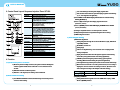
3. Control Panel Layout Sequence Injection Timer SIT-500
1. SIGNAL LED
2. OPEN LED
If injection signal is entered, lamp is turned on.
If gate is opened, lamp is turned on.
When it is manually operated in , lamp is also turned on.
3. DEL
The time until gate is started to be opened after receiving
injection signal. Mode A and mode B operate in the same
way.(Basic setting value : 3 seconds)
4. OPEN
The time when gate is being opened. Counting continues
in mode A until injection signal ends. Gate opens only
during setting time in mode B.
(Basic setting value : 3 seconds)
5. DEL SET Key
A key to set gate opening time after injection signal.
This is used by being pressed simultaneously with key
or key . ("SAVE" is displayed 5 seconds after setting,
and then setting value is saved. If signal is turned on
before "SAVE" display, it operates with the changed value,
and if AC input power is turned off and then turned on,
setting value is not saved.)
6. UP KEY
A key to set up time by pressing DEL or OPEN SET Key
simultaneously.
7. OPEN SET Key A key to set the time when gate is being opened.
This is used by pressing key or key simultaneously.
(Save function is the same as DEL SET key.)
8. DOWN KEY
A key to turn down time setting by pressing DEL or OPEN
SET key simultaneously.
9. MANU Key
A key to be operated when opening gate manually.
Gate is opened only when key is being pressed.
10. MODE A LED Lamp is turned on when it is set as A type.
(Refer to mode setting method)
11. MODE B LED Lamp is turned on when it is being set as B type.
(Refer to mode setting method)
12. Lamp is turned on when gate is opened manually.
13. Module Handle
14. Power switch (On / Off)
15. Module Securing Screw.
4. Function
1) Operation after power is connected
1) When the power is initially connected, the system conducts self-diagnosis
and the segment number starts count from 1 to 9 at an interval of 0.3
seconds.
2) LED blinks from LE1 to LE5 in sequence.
3) After the 1st self-diagnosis, the memory status is indicated.
2) Mode and time unit setting
1) Press MANU & OPEN SET switches simultaneously and connect power to
convert to mode setting.
4
"Set" starts blinking in the delay time display segment 'SET'.
Time set time unit saved in the open time display segment starts blinking
(1, 0.1, 0.01 aligned to the right side)
2) Press MANU and the MODE display LED indicates the selected mode by
blinking (MODE A, B)
3) Press >>(UP) and the open time display segment moves UP
(0.01=>0.1, 0.1=>1)
4) Press <<(DOWN) and the OPEN TIME display SEGMENT moves DOWN
(1=>0.1, 0.1=>0.01)
5) Setting is completed if there is no more input for 5 seconds.
6) All input/output function is suspended during the time of setting.
7) TIME setting not executed
3) Time setting(No blinking)
1) DELAY time adjustment
Setting Delay time through the use of the DEL SET & >>(UP) , DEL SET &
<<(DOWN) switches.
All MODE A, B can be set
Setting range
If there is no adjustment key-in for 5 seconds "Save" is displayed and
setting is completed
Display time functions first when the injection signal is entered during
the set time. (The system functions even during adjustment)
If MANU is pressed during the period of setting, system operates
manually. (Will not function during the period of adjustment)
If the adjustment key remains pressed, data can be entered continuously.
When data are saved from 1 Sec setting to the 999 Sec, 0.1 Sec setting is
displayed as 99.9 Sec and 0.01 Sec setting as 9.99 Sec. (Even the saved
time is changed according to the multiple of the time setting.)
Setting Range
1 Sec Setting
0.1 Sec Setting
0.01 Sec Setting
0--999 Sec
0--99.9 Sec
0--9.99 Sec
2) Adjusting OPEN time
Setting OPEN time through the use of the OPEN SET & >>(UP) , OPEN
SET & <<(DOWN) switches.
5
USER’S MANUAL
Only MODE B can be set.
DELAY time adjustment item : - - same
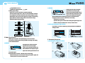
3) Setting output voltage
Remove the rear side of the Timer Case (Remove M4 bolt).
Select the desired voltage from C 24V, AC 110V and AC220V, and insert
the 2 jumpers into the top and bottom for the selected voltage on of the
PCB attached to the rear side of the separate case. (Refer to the following
figure). Match the selected voltage with the Solenoid Valve voltage
specifications (Basic Setting AC 220V)
2) MODE B
Selecting mode B - After the injection
signal has been received, the gate
remains Closed during the DEL time (t1).
After the DEL time has elapsed, the gate
Opens for the OPEN time setting (t2).
After the OPEN time has elapsed, the gate closes and remains closed.
Ex) Injection time:10 seconds DEL Time:3 second setting
OPEN time:4 second setting
Operation:Gate opens 3 seconds after receiving the injection signal, and
remains in the open condition for 4 seconds, and then closes.
3) Gate Opening by Mode Type Selection.
It is possible to set various conditions by selecting the DEL and OPEN timer
settings as below.
5. Mode Specification
A MODE
YUDO Sequence Injection Timer (SIT-500) may be set in two modes.
The opening/closing operation of the gate differs according to the setting
mode as illustrated below.
B MODE
6. Assembly Sequence
1) Assembling the Solenoid Valve Block
1) MODE A
Selecting mode A - After the injection
signal has been received, the gate
remains Closed during the DEL time (t1).
After the DEL time has elapsed, the gate
Opens and remains open until the end of
the injection signal.
Ex) Injection time:10 seconds DEL Time (t1):3 second setting
Operation:Gate opens 3 seconds after receiving the injection signal, and
remains open for 7 seconds, and then closes.
6
7
USER’S MANUAL
Assemble the solenoid valves, seal and air manifold using the M4*35 screws.
Install the Blanking Plugs in the air manifold.
Assemble the Air Supply connector and silencer in air manifold.
Assemble the Solenoid Valve Block Assembly to the mould using the M5*70
flat head cap screws, Ensuring that the sealing gasket is correctly fitted.
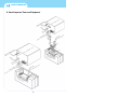
Connect the Solenoid Valve magnet power cable to a 10P or 16P
rectangular connector as indicated below.
7. Mould Machining
Connection sequence
Connector pin no
1, 2
3, 4
5, 6
7, 8
9, 10
11, 12
13, 14
15, 16
Sol Valve No
No. 1 Sol
No. 2 Sol
No. 3 Sol
No. 4 Sol
No. 5 Sol
No. 6 Sol
No. 7 Sol
No. 8 Sol
Connector specification
HAN 10A (250V 16A)
HAN 16A (250V 16A)
MALE P/N:09 20 010 2612
MALE P/N:09 20 016 2612
FEMALE P/N:09 20 010 2812 FEMALE P/N:09 20 016 2812
Assemble the connected
rectangular connector to
mold using M4*12 bolt.
The final assembled equipment
is illustrated below.
8
9
USER’S MANUAL
8. Valve Sequence Timer and Equipment
10