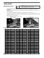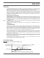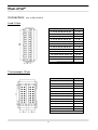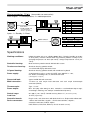
1
Operating Instructions
September 2014
(Subject to technical modifications)
PROFESSIONAL
HUMMEL AG
Lise-Meitner-Straße 2
D-79211 Denzlingen
Telefon: +49(0)7666/91110-0
Fax: +49(0)7666/91110-9799
Internet: www.hummel.com
Table of Contents
General Information
Warning Symbols, Safety Instructions, Warranty, Intended Use, General Information ............... 3
Set-Up, Cleaning, Maintenance, Disposal .................................................................................. 4
Controller
View of the Device ..................................................................................................................... 5
Control Board with Load Circuit Fuses ....................................................................................... 5
Replacing Circuit Fuses ............................................................................................................. 6
Zone / Controller Board Assignment .......................................................................................... 6
Start-Up ..................................................................................................................................... 7
Soft-Start Ramp ......................................................................................................................... 7
Connections: Load / Thermocouple ........................................................................................... 8
Connections: Alarm Connector .................................................................................................. 9
Specifications ............................................................................................................................. 9
Touch Screen Operating
Front View; Main-Functions .......................................................................................................10
“Display” Menu ..........................................................................................................................11
“Table” Menu.............................................................................................................................12
“Parameter” Menu .....................................................................................................................13
“Diagram” Menu ........................................................................................................................14
“Utilities” Menu ..........................................................................................................................15
“System” Menu ..........................................................................................................................16
“Options” Menu .........................................................................................................................17
“Diagnostics” Menu ...................................................................................................................18
LC Operating Panel
Front View .................................................................................................................................19
Alarm Indicators ........................................................................................................................19
Setpoints, Zones Switch off .......................................................................................................20
Function Keys ...........................................................................................................................20
Manual Mode ............................................................................................................................21
Change Parameters ..................................................................................................................22
Parameters, Factory Preset ......................................................................................................23
PC Operation
..................................................................................................................................................23
2
Safety Notices
WARNING: Danger of electric shock.
General danger warning symbol. If you see this pictogram attached to the device,
please refer to this documentation to determine the kind of danger involved and protect
yourself from potential hazards.
Symbol for protective conductor (ground) terminal.
Safety Notices
Carefully read these operating instructions prior to putting the product into service.
Only qualified personnel with qualified electrotechnical knowledge may service the device.
Be sure to disconnect the mains plug before opening the housing!
When replacing fuses, be sure to use the same type of fuse (see “Replacing Fuses“).
Prior to plugging in the mold cables, verify that all connectors have been properly connected
(see “Connections” or connection diagram for special pin assignments).
Check power supply cable and mold cables for potential defects on a regular basis! If cable
sheath is damaged, be sure to use a new connecting cable!
Warranty
All
plug-in controllers are subject to a 2-year warranty starting on the day of
shipment of the product. Excluded from coverage is damage due to improper handling,
wrong connection or non-intended use (see below).
Return goods must be sent to HUMMEL AG’s EL Division using the original packaging,
postage prepaid.
Intended Use
The
plug-in controllers are industrial temperature controllers designed for
regulating the temperature of hot-runner molds. To this end, the temperature of each control
zone is monitored by a temperature sensor whose input is used to adjust the power output
for the heating element as appropriate. Using the device for other purposes may
compromise its protective functions.
An external temperature fuse must be used for overtemperature protection in the event of
malfunction.
The manufacturer shall not be liable for damage due to improper use of the device.
General Information
A separate control zone is required for each load to be connected.
A “control zone” consists of a temperature sensor input and a load output including a fuse.
When wiring the molds, be sure to assign them to the correct pins (see “Connections”).
All unused control zones must be switched off.
A heat-resistant flexible cable must be used as a connecting lead for the load circuits. For
the temperature sensors, a special compensating lead is required! Leads and cables are
available as original accessories.
3
Set-Up
The device includes built-in, powerful fans that reliably prevent overheating of the output
stage during operation. The corresponding ventilation slots are located on the underside and
the rear side of the device. Make sure that air supply to and through these openings is not
blocked!
Cleaning
The external surfaces of the device and the operating panel may be cleaned with a soft cloth
saturated with alcohol. Do not use acid cleaners or scouring agents!
To prevent malfunction, the operating panel should only be cleaned after the device has
been switched off.
Maintenance
The device must be regularly subjected to a safety check complying with BGV A2
requirements (protection against accidents).
It is recommended to clean the dust filters of the fans at regular intervals. Replace the filters
as appropriate, depending on their working condition and duration of use.
In addition, the ventilation slots should be regularly checked for obstruction and cleaned if
necessary. However, this may only be done by qualified service personnel with adequate
electrotechnical knowledge.
No other maintenance work is required for the device beyond the tasks specified above.
Should malfunction occur, please contact the manufacturer.
Disposal
Once the device has reached the end of its service life, feel free to return it to the
manufacturer for proper disposal.
This device satisfies the essential protection requirements
specified in pertinent EU Directives (as of 2010)
4
View of the Device
Front side
Rear side
Operating panel connector
Controller board 1
Alarm connector
Interface connector
Main
switch
Thermocouple
connectors
Load connector
Controller board 16
Power supply cable
Controller Board with Load Fuses
IMPORTANT NOTICE:
l
k
j
i
h
g
f
e
d
c
b
a
Each controller board is designed for controlling
6 zones. The cards can be inserted into any
free slot.
Be sure to turn off the device before removing a
controller board! Following board exchange, the
device must be restarted.
To replace the load circuit fuses, unlock the
corresponding control card (rotate the 4 locks
by 90°), then withdraw card.
When replacing fuses, be sure to use fuses of
the same type (16 A FF); see “Replacing
Fuses“!
5
Replacing Fuses
WARNING
Danger of death from electric shock!
- Before starting any work on the device, be sure to pull mains plug!
The device may only be serviced by qualified personnel with consolidated electrotechnical
knowledge.
2 fuses for the main power supply are located inside the device. When replacing them, be sure to use fuses of
the same type/rating.
Each control card is designed for controlling 6 zones. For assignments, see tables below.
To replace the load circuit fuses, unlock the controller board (rotate lock by 90°) and withdraw card. Use the
auxiliary tool (attached inside the front door) to exchange the fuses as illustrated below. Be sure to use only
replacement fuses of the same type!
To reassemble the device, proceed in reverse order.
Removing fuses
Installing fuses
Assignment of zones to control cards
Zone
1
2
3
4
5
6
7
8
9
10
11
12
13
14
15
16
17
18
19
20
21
22
23
24
25
26
27
28
29
30
31
32
Board
1
1
1
1
1
1
2
2
2
2
2
2
3
3
3
3
3
3
4
4
4
4
4
4
5
5
5
5
5
5
6
6
Fuses
a+b
c+d
e+f
g+h
i+j
k+l
a+b
c+d
e+f
g+h
i+j
k+l
a+b
c+d
e+f
g+h
i+j
k+l
a+b
c+d
e+f
g+h
i+j
k+l
a+b
c+d
e+f
g+h
i+j
k+l
a+b
c+d
Zone
33
34
35
36
37
38
39
40
41
42
43
44
45
46
47
48
49
50
51
52
53
54
55
56
57
58
59
60
61
62
63
64
Board
6
6
6
6
7
7
7
7
7
7
8
8
8
8
8
8
9
9
9
9
9
9
10
10
10
10
10
10
11
11
11
11
6
Fuses
e+f
g+h
i+j
k+l
a+b
c+d
e+f
g+h
i+j
k+l
a+b
c+d
e+f
g+h
i+j
k+l
a+b
c+d
e+f
g+h
i+j
k+l
a+b
c+d
e+f
g+h
i+j
k+l
a+b
c+d
e+f
g+h
Zone
65
66
67
68
69
70
71
72
73
74
75
76
77
78
79
80
81
82
83
84
85
86
87
88
89
90
91
92
93
94
95
96
Board
11
11
12
12
12
12
12
12
13
13
13
13
13
13
14
14
14
14
14
14
15
15
15
15
15
15
16
16
16
16
16
16
Fuses
i+j
k+l
a+b
c+d
e+f
g+h
i+j
k+l
a+b
c+d
e+f
g+h
i+j
k+l
a+b
c+d
e+f
g+h
i+j
k+l
a+b
c+d
e+f
g+h
i+j
k+l
a+b
c+d
e+f
g+h
i+j
k+l
Start-Up
The PROFESSIONAL hot-runner controllers are designed for connection to a three-phase power
supply source (see “Specifications”). The unit features a CEE plug for this purpose. The mains switch,
which disconnects the device completely from the power supply, is located on the rear panel.
Connect the operating panel. If you use a PC for controller operation, connect the connecting cable to
the “interface” connector. After checking carefully that all connections have been made correctly,
connect the mold to the controller. The alarm connector (accessory) allows you to establish a
connection to the injection molding machine as well. Connect the mains cable, then turn on the
controller via the mains switch.
Touch Screen / PC operating
TIP!
Following initialization of the system and parameter loading, the operator must decide whether to use
the Setting Wizard or not. The Wizard helps you to make the main settings required for starting
production in just a few steps. Alternatively, adjust the setpoint values or load a mold program stored in
the system’s memory. Be sure to switch off all control zones that are not used currently! (See
“Parameters” menu)
The HELP button gives you access to the Help function. This function explains all the operating/setting
options offered in the currently active menu.
Following careful verification of the correctness of all settings, operate the I/O button to start the
heating process.
LC Operating Panel
Turn on the mains switchhis triggers a query prompting you to decide whether the control parameters
should be optimized for the respective hot-runner mold or not. Optimization is necessary only when a
mold is connected for the first time. Setting optimization to OFF (OPTI-N) accelerates the heating-up
process. However, if the setpoint values are retrieved from the tool memory, optimization is always
required. If no entry is made, the system will start without optimization after 1 minute.
The controller will now heat up all molds in a uniform manner. Moist heating elements are dried in the
process (soft-start ramp). If the “compound heating” option is used, all zones are heated up at the
same speed, thus reducing stress in the mold material. The heat-up speed of the soft-start ramp can
be adjusted via the “Options” menu.
When heating up molds for the first time, the controller automatically determines the best control
parameters for the connected heating zones. Therefore, to ensure optimal control results, do not
connect the device to warm molds!
It is possible to exchange the operating panel “in process”. This causes no interruptions. Just connect
your operating panel to the “operating panel” connector.
Soft-Start Ramp
Active by: Start-Up, Heating after standby or alarm.
Overtemperature
Undertemperatur
e
Setpoint
Pause
Ramp 2 (K / s)
Start-up temp.
Ramp 1 (K / s)
7
Connections
(acc. to DIN 16765-A)
Load, 24-pin
Zone
PIN
1, 13, 25, 37, 49, 61, 73, 85
1 / 13
2, 14, 26, 38, 50, 62, 74, 86
2 / 14
3, 15, 27, 39, 51, 63, 75, 87
3 / 15
4, 16, 28, 40, 52, 64, 76, 88
4 / 16
5, 17, 29, 41, 53, 65, 77, 89
5 / 17
6, 18, 30, 42, 54, 66, 78, 90
6 / 18
7, 19, 31, 43, 55, 67, 79, 91
7 / 19
8, 20, 32, 44, 56, 68, 80, 92
8 / 20
9, 21, 33, 45, 57, 69, 81, 93
9 / 21
10, 22, 34, 46, 58, 70, 82, 94
10 / 22
11, 23, 35, 47, 59, 71, 83, 95
11 / 23
12, 24, 36, 48, 60, 72, 84, 96
12 / 24
Ground connect to housing!
Thermocouple, 32-pin
Zone
PIN
1, 13, 25, 37, 49, 61, 73, 85
1+/9-
2, 14, 26, 38, 50, 62, 74, 86
2 + / 10 -
3, 15, 27, 39, 51, 63, 75, 87
3 + / 11 -
4, 16, 28, 40, 52, 64, 76, 88
4 + / 12 -
5, 17, 29, 41, 53, 65, 77, 89
5 + / 13 -
6, 18, 30, 42, 54, 66, 78, 90
6 + / 14 -
7, 19, 31, 43, 55, 67, 79, 91
7 + / 15 -
8, 20, 32, 44, 56, 68, 80, 92
8 + / 16 -
9, 21, 33, 45, 57, 69, 81, 93
17 + / 25 -
10, 22, 34, 46, 58, 70, 82, 94
18 + / 26 -
11, 23, 35, 47, 59, 71, 83, 95
19 + / 27 -
12, 24, 36, 48, 60, 72, 84, 96
20 + / 28 -
Ground connect to housing!
8
Alarm connector, 12-pin
(alarm cable see accessories)
Alarm outputs: 1 = overtemperature, 2 = undertemperature
M
Ö
S
max. SELV:
33VAC/70VDC, 2A
* Stop machinery
* Release production
PIN
Colour
Function
1
blue
Ö - Alarm 1 (Overtemp)
2
pink
M - Alarm 1 (Overtemp)
3
grey
S - Alarm 1 (Overtemp)
6
red
S - Alarm 2 (Undertemp)
7
black
M - Alarm 2 (Undertemp)
8
purple
Ö - Alarm 2 (Undertemp)
Inputs: 1 = Standby, 2 = Boost
PIN
Colour
Function
4+5
white + brown
E1 - Standby
10 + 12
green + yellow
E2 - Boost
Switch contact
Specifications
Working conditions:
Indoor Operation only, max. altitude 2000m M.S.L. Relative humidity up to 80%
at 30°C (86°F), moisture condensation not permitted, pollution severity level 2,
operating temperature 10...40°C (50–104°F), storage temperature 0…50°C (32–
122°F)
Controller housing:
Metal enclosure powder-coated, with lockable castors
Touchscreen housing:
Aluminum housing, powder-coated;
15“-SVGA-LCD display with touchscreen
LC panel housing:
Power supply:
Aluminum housing, powder-coated; with membrane keyboard
4-conductor three-phase system 3L+N+PE, 230 / 400VAC +/- 10%,
50…60 Hz; Overvoltage class II, CEE 63A connector
(other Supplies on request)
Connected load:
approx. 44kW with 63A connector
Mold connection:
12 zones to each 24-pin load connector and each 32-pin thermocouple
connector (HAN-A)
Thermocouple:
Type J, L or K
Power output:
Max. 16A (duty ratio <80%)per zone, contactless semiconductor output stage,
zero voltage switching, max. 48A per controller board (6 zones)
Control range:
50...500°C (122…932°F). Control accuracy better 1°C (if hotrunner permits)
Load fuse:
16 A FF (super fast)
Controller boards:
Plug-in cards, each for 6 zones with load circuit fuses. Replaceable without tool
Device connectors:
1 Alarm connector M23, 12-poles; 1 Panel connector M16, 10-poles;
2 Interface connectors SUB-D, 9-poles
USB; Ethernet; VGA; PS2; RS232 (1 of each at touch screen).
9
Touch Screen Operating Panel
Menu bar
Boost
Start / Stop
heating
Alarm
Standby
Navigation
System OFF
Diagram
Select Menu:
Via menu bar, selection directly on the screen.
Help:
The HELP button accesses the help function of the current menu window. You can open either
the user manual or the Setting Wizard.
Setpoint:
Can be entered directly via the “Parameters” menu. In the “Display” or “Table” menu, select the
zone of your choice and then SET to adjust the setpoint value. For groups, see “Group”.
Zones OFF:
You can deactivate zones individually via the “Parameters” menu.
Group:
Select first zone and last zone, then use the GROUP button to create a group. You can add
additional zones at your choice. Use the SET button to set the setpoint value, then click
CLEAR to return to normal operation. Button F1 allows you to define, designate and mark
groups (e.g. for multi-component molds). F2 highlights the 6 variable groups.
Start operation: To activate the heating function, click the I/O button.
Boost:
Temporary temperature increase, either with Boost button or via alarm connector.
Standby:
Temperature reduction for all active zones with Standby button or via alarm connector.
Alarm:
The Alarm button allows you to call up all currently active alarm messages.
Print:
The PRINT button allows you to print the current screen content.
Turn off:
First, terminate all control processes with the I/O button. Click the END button to close the
operating system, then turn off the device via the mains switch.
10
“Display” Menu
Function:
Standard view in operating mode. The screen displays all control zones belonging
to the controller, with zone name, actual value, setpoint value and % power output.
In addition, the controller status, the status of the alarm inputs and outputs and all
active alarm messages are indicated as well.
Setting:
Use the SET button to enter the setpoint value of your choice, if ready press
CLEAR to return to operating mode. You can also make this setting for a whole
group of control zones by selecting the corresponding zones with the GROUP
function.
The left/right buttons enable you to display the previous/next block of zones; for
single (line-by-line) steps, use the up/down buttons.
Submenus:
No submenus available.
TIP!
The “% power output” bargraphs give you an overview of the connected heat load
(nozzle or manifold). Once the set setpoint value has been reached, the output
should be no higher than 80%. If higher, the capacity of the heating system is
probably insufficient.
The GROUP and F1 (fixed-group) functions enable you to designate and mark the
respective systems when using multi-component molds. These systems can then
also be modified and started separately. F2 highlights the groups and displays them
separately.
11
“Table” Menu
Function:
This screen displays all control zones with zone name, actual value, setpoint value,
% power output, temperature unit, load current, boost and standby temperatures. In
addition, the controller status, the status of the alarm inputs and outputs and all
active alarm messages are indicated as well.
Setting:
Use the SET button to enter the setpoint value of your choice, if ready press
CLEAR to return to operating mode. You can also make this setting for a whole
group of control zones by selecting the corresponding zones with the GROUP
function.
The left/right buttons enable you to display the previous/next block of zones; for
single (line-by-line) steps, use the up/down buttons. The scroll bar on the right side
of the screen can be used for direct navigation.
Submenus:
No submenus available.
12
“Parameter” Menu
Function:
This screen displays the parameter set for a zone. This menu allows you to name zones and set the
zone parameters.
Setting:
Zones are selected in the top left field and can be given a name in the field immediately to the right.
The following two fields of this line indicate first the controller board (module) and then the channel of
this card. The following line allows you to switch the zone ON and OFF or switch to a different mode of
operation. “°C” stands for control mode, “%” for manual operation and the measuring symbol for
measurement zones. If you select manual operation, the output power must be additionally set (in %
power output) under Default Settings. The measurement zones enable you to display the mold
temperature and monitor mold cooling.
WARNING: There is no mold temperature monitoring in manual operation! Danger of destruction of
the connected heating system! The Substitute field allows you to set an alternative sensor for
providing the actual value for the zone in the event of sensor breakage.
In the Default Settings block, you can set the setpoint value, the boost and standby temperature and
the output power for manual operation in %.
The Channel State block provides information on the operation state and the actual load current of the
respective zone. The Current Limit field allows you to set the maximum permissible output current. If
the set level is exceeded, overcurrent alarm is automatically triggered.
The power output monitoring function compares the average output value to a reference value. If
the monitoring function is active, the system detects deviations caused e.g. by leakages in the
hotrunner system.
During the optimization phase, the controller checks the best control parameters for all the heating
elements connected. These values can be overwritten by adjusting the control parameters. However,
this leads to enhanced control accuracy only in exceptional cases and therefore should only be done
by experts!
Submenus:
•
No submenus available.
Depending on access level, not all setting options may be available! (See also “Options” menu)
13
“Diagram” Menu
Function:
This menu enables you to define 10 different diagrams with 10 different curves
each. Recording takes place during operation after pressing the “start all” button.
You can stop the recording process with “stop all ”.
Setting:
You can select the diagrams in the top left corner. The fields to the right enable you
to designate, activate and reset the respective diagram.
The “Recording” block allows you to select the recording intervals. The duration of
the recording process is automatically determined by the program. You can also
choose between continuous and non-continuous recording.
The “Y-axis” block allows you to set the range of values for the recording.
By clicking the “zone” field after selecting the zone of your choice, you can define
the type of value to be recorded. Options include: setpoint or actual value, for
temperature as well as % output power.
Submenus:
Clicking the OK field or operating the DIAGRAM button calls up the View mode.
Clicking the field/button again returns you.
14
“Utilities” Menu
Function:
This menu is used for displaying photos of any kind, e.g. mold halves or injectionmolded parts, as well as screen printouts for the system file or stored recording
data.
Setting:
On the bottom left, you can select between pictures, printings or datasave view. All
saved files are shown in the list above this field.
The zoom in, zoom out, original size and window size fields enable you to adjust the
image as required.
Image files can be stored in the program directory under Images, preferably as jpg
or bmp files.
Stored or running data records can be opened and zoomed and placed to the right
recording time with the image tool
Submenus:
Clicking the printings / pictures / datasave field switches between image, printout or
stored data view.
Tip:
Photos of mold halves can easily be marked with the mold cavities (e.g. using
WINDOWS® Paint). When stored as an image, such marking or lettering can be
helpful in identifying zones and setting zone parameters.
15
“System” Menu
Function:
This menu allows you to manage the mold memory “molds” and the “system
parameters”. Besides, the “system overview” provides information on the status and
the firmware version of the various controller boards.
Setting:
In the “molds” submenu, all parameter values of a running mold can be managed.
The “save as”, “save”, “load” and “delete” buttons are intended to guide the user
through this submenu. Once all parameters have been set correctly, they can be
saved with “save as” by entering a name for the part or simply the drawing number.
If changes have been made to an existing mold, these are saved with the “save”
button. To start control operations after the system had been switched off, the
appropriate program must first be loaded via the “load” function. The read-only data
record Default Settings stores the factory-preset parameters.
The “system parameter” submenu allows you to enter “global” values that are valid
for the entire system (e.g. soft-start parameters).
Submenus:
“system parameter”: For entering parameter data for all zones.
“system overview”: Indicates the status and the firmware version for each controller
card (module).
“molds”: Manages mold data with change history (mold memory).
•
Depending on access level, some setting options may not be available! (See also menu options)
16
“Options” Menu
Function:
There are various access levels that differ in the scope of the setting and viewing options
they provide. For Levels 1 and 2, 4-digit numerical passwords are required. Level 1 (user
level) is intended for production, Level 2 (master level) for parameter setting. All higher
access levels should only be used by system administrators!
Setting:
The “access” block is used for entering the passwords for Levels 1 and 2. Once the
passwords have been saved, access will be possible only after entering the correct password
in each case!
In the ”startup behaviour” block, the “compound heating” function or the “optimization”
function can be activated or deactivated. If the compound heating function is activated, the
fastest zone (e.g. nozzles) will wait for the slowest zone (e.g. manifold). This prevents mold
stress as far as possible during the heat-up process. During the soft-start phase, the
optimization function determines the best control parameters. However, this is required only
during the initial start of each mold.
The ”display” section allows you to select the basic temperature unit (°C or °F) and the
interactive language of your choice.
Data recording (e.g. for quality assurance purposes) can be activated and deactivated in the
”data backup” block. Besides, you can set the monitoring interval here. The info button gives
you access to a list of zones that have been activated for data recording. Such activation is
carried out via the actual temperature and output fields of the Parameters menu, either
individually or groupwise. The log data is stored in a special directory and can be retrieved
from there as an ASCII file.
Submenus:
“Start explorer” : Direct access to the data management area of the operating system.
“Error log” : Provides a list of all alarms that have been triggered, with date and time.
“System log” : Provides a list of all user actions, with date and time.
•
Depending on access level, some setting options may not be available!
17
“Diagnostics” Menu
Function:
Checks the wiring of the connected mold and indicates wiring or system errors. The
checks are performed for each zone separately. If the connected heating system
reaches the target temperature (offset) within the preset time, the zone is O.K.
Currently running tests are indicated for the respective zone. Should wiring or
system problems be detected, an error message is displayed.
Setting:
SET allows you to select the zones to be checked. In this way, it is possible to
select only the relevant heating circuits, e.g. after completion of repairs.
The ”temperature offset” field is used for setting the temperature differential by
which the temperature must be increased within the desired time interval. This value
can be entered via the ”maximum duration” field. The maximum % power output can
be set manually via the ”output” field.
Clicking the “start diagnostics” field starts the check and clicking ”stop diagnostics”
terminates it. Given p.e. 60 zones, the diagnostic process can take several hours if
the time range is utilized!
Submenus:
No submenus available.
TIP!
Recording the results of the diagnosis helps you to identify defective heating zones
later by assessing deviations from the % power output.
18
LC Operating Panel
Alarm indicators
Actual Value
Setpoint Value
Heating pulse
indicator
VIEW BLOCK
button
1-24, 25-48, etc.
Dialog window
SETPOINT
button
BOOST
button
OUTPUT
POWER
button
CANCEL PROGRAMMING/
ZONE OFF
button
UP / DOWN
buttons
PROGRAMMING /
ENTER
button
MANUAL
button
STANDBY
button
Alarm Indicators
Thermocouple alarm
Lights up in case of TC malfunction (open, reversal). The actual value display shows "- -" or the temperature of the controller by TC reversal. If Automode is active, the
display shows alternating " - - - " and " - A - ".
Temperature deviation alarm
Flashes during the heating-up phase of the soft-start ramp. Lights up continuously if
the temperature exceeds or falls below set limits. In case of overtemperature, the
power supply is interrupted.
Load alarm
Lights up if the set maximum current is exceeded or flashes by open load. In case of
overload, the power supply is interrupted.
19
Setting the Setpoint Value / Switching off Control Zones
Button
Command
Display
Display setpoint
Upon pressing this button, the setpoints are displayed, or
oFF for the non-active zones. The button indicator lights up.
The dialog window shows Z ALL.
Select zone
The selected zone is indicated in the Dialog window.
Z ALL for all zones. Z COPY allows one setting for all active
zones.
Confirm zone
The selected zone number flashes, or all with Z ALL.
TEMP is displayed in the Dialog window. At Z COPY the
common setpoint is diplayed in the center field.
Set setpoint,
- switching off zone
Change the setpoint with the UP / DOWN buttons.
Keeping the ESC / OFF button pressed for a few
seconds and press again, switches off the selected
zone.
Press the OK / PRG button 2 times will switch on the
selected zone. The last setpoint before deactivating
this zone will be set again.
- switching on zone
Confirm setting
Stores the changed values.
Setpoint display off
Button indicator off. Back to standard run mode.
Increased setpoints will be reached with 100% power
output!
* Cancel without saving:
Cancel
Pressing this button will lead back one programming
step without storing the changed value.
Function Keys
Button indicator lights up upon activation of respective button (On).
Output power
Pressing this button once indicates the output power
in % of the maximum in the setpoint display. Pressing
it again shows you the load current (in amperes). The
button indicator % or A lights up. Pressing once more
returns to the setpoint value.
Boost function active
Increases temperature temporarily.
(also externally via alarm connector)
Standby active
Decreases temperature permanently.
(also externally via alarm connector)
Pressing the button longer, switches off the outputs. The
button LED starts flashing. To resume operation, push the
button again.
Stop operation
* For manual operation, see separate section.
20
Manual Mode
ATTENTION:
In this mode the hotrunner is not controlled and not switched off in case of
overtemperature. So overtemperature and damaging is possible!
Button
Command
Display / Result
Manual mode
Upon pressing this button the setpoint display of all
inactive zones shows oFF.
The button indicator lights up.
Select zone
The selected Zone is displayed in the dialog window.
Confirm zone
The selected zone no. is flashing.
The dialog window shows PULS.
Set power value,
With the UP / DOWN buttons in percent.
- manual mode Off
Keeping the ESC / OFF button pressed for a few
seconds and press again, switches off the manual
mode of the selected zone.
- manual mode On
Press the OK / PRG button 2 times will switch on the
manual mode of the selected zone. The last power
value before deactivating will be set again.
Confirm setting
Stores the selected power value.
Exit setting
Button indicator off. Back to run mode. The setpoint
display of the zones in manual mode will toggle
between the selected power value in percent and
PLS.
* Exit Setting without storing:
Cancel
Pressing this button will lead back one programming
step without storing the changed value.
* To reset (deactivate) manual operation, just turn off the device with the main
switch!
21
Change Parameters
Button
for more
than 5 sec.
Command
Display
Change Parameters
The Dialog window shows Z ALL while the zone
numbers are shown in the setpoint displays.
Select zone
The selected zone is indicated in the dialog window.
Z ALL for all zones.
Confirm zone
The selected zone no. is flashing, or all zones at Z ALL
The Dialog window shows the first menu item.
Select menu item
The Dialog window shows the respective menu item.
Confirm menu item
Currently used parameters are shown in the setpoint
Display.
Change values
Modified parameters are shown in the setpoint display.
(see Parameters / Factory Preset)
Store *
Modified parameters will be stored.
Exit setting
Dialog display off. Back to standard run mode.
* Exit programming without storing:
Cancel
Pressing this button will lead back one programming
step without storing the changed value.
22
Parameters (Factory Preset)
Menu Item
Name
Function
Range
Standard
Factory-preset
The following parameters can only be set for all zones
OVTEMP
Overtemperature
Limit value, alarm output 1
0 - 50°C above
setpoint
10°C
UNTEMP
Undertemperature
Limit value, alarm output 2
0 - 50°C below
setpoint
10°C
RMPEND
Ramp end
Final temperature ramp 1
120°C
RMP T1
Rise, ramp 1
Heating speed, ramp 1
RMP T2
Rise, ramp 2
Heating speed, ramp 2
RMPPSE
Ramp pause
AUTO
Automode *
Pause between ramps 1 + 2
Automatic control if TC is open
(average output power)
Temperature below setpoint
Type of Thermocouple
°C or °F
Set to factory preset values
Software version controller card
Lock function
Deactivates softstart
synchronisation
80 - 120°C
1 - 10 seconds
for 1°C
1 - 10 seconds
for 1°C
1 - 10 minutes
TEMPDN
TC TYP
UNIT
PRESET
FW VER
CODE
SYNC
Standby
Thermocouple
Temperature unit
Preset
Actual firmware version
Access code
Compound heating
4 seconds
2 seconds
1 minute
1 = On; 0 = Off
0 (Off)
10 – 200°C
J, L or K
C or F
V…
0 - 250
50°C
J
°C
0 (inactive)
1 = On; 0 = Off
1 (On)
5–60°C
0–180 s
1–16 A
50–500°C
20°C
20 seconds
16 A
450°C
The following parameters can be set individually for each zone
TEMPUP
UPTIME
CURR
TMPMAX
Boost function
Boost time
Overload
Setpoint limitation
Temperature above setpoint
Duration of boost process
Limit value
Max. setpoint value permitted
* Automode function is available only after failure-free operation for approx. 15 min!
PC Operation
PC-based operation requires a licensed software available from HUMMEL AG.
Following installation of the software according to the instructions supplied with the product, you can
operate the controller in the same way as in the touchscreen version. The scope of functions
available is also identical with the touchscreen version, but the mouse pointer is now used for
navigation.
23