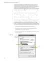
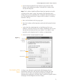
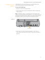
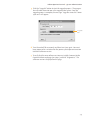
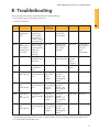
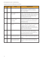
1
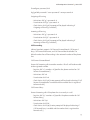
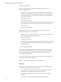
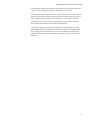
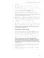
Iridium OpenPort Terminal
User Manual
9801
9701
I Above Decks Equipment
I Below Decks Equipment
Notice:
Trademark Information
Disclaimer
Every effort has been made to ensure the correctness and completeness of
the material in this document. No company shall be liable for errors contained
herein. The information in this document is subject to change without notice.
No warranty of any kind is made with regard to this material, including, but not
limited to, the implied warranties of merchantability and fitness
for a particular purpose.
Beta Test - June User Rev. 1
I Contents
1 Introduction . . . . . . . . . . . . . . . . . . . . . . . . . . . . . . . . . . . . . . . . . . . . . . . . . 1-1
About this Manual . . . . . . . . . . . . . . . . . . . . . . . . . . . . . . . . . . . . . . . . . 1-1
Terms to Know . . . . . . . . . . . . . . . . . . . . . . . . . . . . . . . . . . . . . . . . . . . . . 1-1
Reference Documents . . . . . . . . . . . . . . . . . . . . . . . . . . . . . . . . . . . . . 1-1
2 Safety . . . . . . . . . . . . . . . . . . . . . . . . . . . . . . . . . . . . . . . . . . . . . . . . . . . . . . . .2-1
Electrical Shock Warning . . . . . . . . . . . . . . . . . . . . . . . . . . . . . . . . . . 2-1
Radiation Hazard . . . . . . . . . . . . . . . . . . . . . . . . . . . . . . . . . . . . . . . . . . 2-2
3 Overview . . . . . . . . . . . . . . . . . . . . . . . . . . . . . . . . . . . . . . . . . . . . . . . . . . . . 3-1
Iridium Satellite Communications . . . . . . . . . . . . . . . . . . . . . . . . . 3-1
OpenPort Terminal Components . . . . . . . . . . . . . . . . . . . . . . . . . . 3-1
4 System Start-up . . . . . . . . . . . . . . . . . . . . . . . . . . . . . . . . . . . . . . . . . . . . . . 4-1
SIM Validation . . . . . . . . . . . . . . . . . . . . . . . . . . . . . . . . . . . . . . . . . . . 4-2
Starting the System . . . . . . . . . . . . . . . . . . . . . . . . . . . . . . . . . . . . . . . 4-2
5 Voice Calls . . . . . . . . . . . . . . . . . . . . . . . . . . . . . . . . . . . . . . . . . . . . . . . . . . . 5-1
Voice Call from Handset . . . . . . . . . . . . . . . . . . . . . . . . . . . . . . . . . . . 5-1
Voice Call using Prepaid Card . . . . . . . . . . . . . . . . . . . . . . . . . . . . . . 5-2
Supplemental Services . . . . . . . . . . . . . . . . . . . . . . . . . . . . . . . . . . . . 5-2
Captains PIN Feature . . . . . . . . . . . . . . . . . . . . . . . . . . . . . . . . . . . 5-2
Call Barring . . . . . . . . . . . . . . . . . . . . . . . . . . . . . . . . . . . . . . . . . . . . .5-2
Call Forwarding . . . . . . . . . . . . . . . . . . . . . . . . . . . . . . . . . . . . . . . . .5-3
Voice Mail . . . . . . . . . . . . . . . . . . . . . . . . . . . . . . . . . . . . . . . . . . . . . . 5-4
6 Data Transfer . . . . . . . . . . . . . . . . . . . . . . . . . . . . . . . . . . . . . . . . . . . . . . . . 6-1
Computer Set-up . . . . . . . . . . . . . . . . . . . . . . . . . . . . . . . . . . . . . . . . . 6-1
PC & Network Configuration . . . . . . . . . . . . . . . . . . . . . . . . . . . . . 6-2
Accessing the Internet . . . . . . . . . . . . . . . . . . . . . . . . . . . . . . . . . . . . 6-5
7 System Administration . . . . . . . . . . . . . . . . . . . . . . . . . . . . . . . . . . . . . . 7-1
ISU Web Pages . . . . . . . . . . . . . . . . . . . . . . . . . . . . . . . . . . . . . . . . . . . . 7-1
Configuring the System . . . . . . . . . . . . . . . . . . . . . . . . . . . . . . . . . . . 7-5
Software Upgrade . . . . . . . . . . . . . . . . . . . . . . . . . . . . . . . . . . . . . . . . 7-8
8 Troubleshooting . . . . . . . . . . . . . . . . . . . . . . . . . . . . . . . . . . . . . . . . . . . . . 8-1
Below Decks Equipment (BDE) LEDs . . . . . . . . . . . . . . . . . . . . . . . .8-1
Access Denied . . . . . . . . . . . . . . . . . . . . . . . . . . . . . . . . . . . . . . . . . . . . 8-3
Appendix A . . . . . . . . . . . . . . . . . . . . . . . . . . . . . . . . . . . . . . . . . . . . . . . . . . . . . A-1
Declaration of Conformity . . . . . . . . . . . . . . . . . . . . . . . . . . . . . . . . . . . .A-1
1 I Introduction
Thank you for purchasing the state of the art Iridium OpenPort
Terminal. Iridium is the only provider of truly global satellite voice and
data communications solutions with complete coverage of the entire
earth including oceans, airways and even polar regions. The Iridium
OpenPort Terminal delivers reliable, secure, real-time, simultaneous
high quality voice and up to 128kbit/s data connection to the Iridium
satellite network from any point on the globe.
About This Manual
This manual provides you with complete information on the use of
the OpenPort Terminal. This includes the following:
•
•
•
•
•
Terms to Know
Starting the system
How to make and receive voice calls
How to transfer data across the Internet
System Administration
Troubleshooting
ADE: Above Decks Equipment, the radiating unit.
BDE: Below Decks Equipment, the user interface unit.
ISU: Iridium Subscriber Unit, The ADE and BDE together.
POTS: Plain Old Telephony System
SIM: Subscriber Identity Module
PSU: Power Supply Unit Provisioned: A term used to indicate the SIM card is activated for
voice and data connection. This can only be done by the Service
Provider.
1.1
1 Introduction
Iridium OpenPort Terminal I 1 Introduction
1.2
Iridium OpenPort Terminal I 2 Safety
Warnings
The ADE and the BDE should be installed by a qualified professional
technician trained in the installation of marine electronics and antennas.
Failure to comply with these precautions or with specific warnings on the
equipment or in this manual violates the safety standards of the design,
manufacture and intended use of this equipment. Iridium Satellite LLC
assumes no liability for the customer’s failure to comply with these
requirements.
2 Safety
2 I Safety
! WARNING!
The Below Decks Equipment (BDE) contains extra low
voltage that may cause serious injury if opened or not
grounded. Ensure the unit is properly grounded before
operation and do not, under any conditions, open or
dismantle the BDE.
Note: Only a qualified professional technician trained in the installation
of marine electronics and antennas should remove the installation cover
on the BDE.
! CAUTION!
The Above Decks Equipment (ADE) transmits radio
frequency (RF) that is potentially harmful. When the
system power is ON keep all personnel a minimum of 1.0
m (3.3 ft.) from the antenna (see Radiation Hazard).
Figure 2 I 1
POWER
STATUS
SIGNAL
GPS
SIM
on / off
Installation
cover
data
voice 1
SIM cover
2.1
voice 2
Iridium OpenPort Terminal I 2 Safety
Radiation Hazard
Figure 2 I 2
Potentially hazardous radio frequency (RF) is transmitted from the ADE.
To avoid risk to personnel it is recommended people keep the following
distances between themselves and the antenna when the system power
is ON.
ation Hazar
i
d
d
Ra
1.0
m
(3
f
.3
t.)
2.2
Description
Minimum Distance from Antenna
within 0° - 180° of the antenna
elevation range
1.0 m (3.3 ft.)
Iridium OpenPort Terminal I 3 Overview
3 I Overview
Iridium Satellite
Communications
Iridium’s constellation consists of 66 low-earth orbiting (LEO), crosslinked satellites operating as a fully meshed network and supported
by multiple in-orbit spares. Iridium has gateways in Arizona and
Hawaii and additional telemetry, tracking and control facilities in
Alaska, Canada and Norway. It is the largest commercial satellite
constellation in the world.
3 Overview
Figure 3 I 1
OpenPort Terminal Above Decks Equipment
Components
Figure 3 I 2
1
1. Above Decks Equipment (ADE)
The Above Decks Equipment (ADE) provides the communication
connection between the BDE and Iridium’s satellites. The ADE will
automatically locate and track Iridium satellites overhead.
3.1
Iridium OpenPort Terminal I 3 Overview
Below Decks Equipment
Figure 3 I 3
2
4
power
status
signal
GPS
®
SIM
off / on
3
data
voice 1
voice 2
voice 3
6 SIM card, reset button
and on/off switch are
located behind panel
2. Below Decks Equipment: The Below Decks Equipment (BDE) is the
modem to which you connect your telephones and computers. It is
capable of handling three POTS/RJ11 telephone handsets and one
Ethernet data connection.
3. ADE / BDE Cable: The cable connects the ADE to the BDE. It is
shielded and has a waterproof connection for the ADE.
4. AC Power Supply Unit: The AC Power Supply Unit (PSU) provides
power to the BDE.
5. POTS Handsets (not shown): Three handsets are provided with your
OpenPort Equipment: a Captain’s Phone, for installation on the
bridge, and two Crew Phones, designed for quick access to Iridium
Crew Calling services.
6. SIM: The SIM card validates the system at start-up, allows
connection to the Iridium network and provisions the appropriate
phone and data lines.
3.2
Iridium OpenPort Terminal I 4 System Start-up
4 I System Start-up
Now that the system has been set up by the installer and is ready for
use when it is turned ON it is important to conduct the following
checks before using the system:
1. Is the equipment properly grounded and is there power to
the units?
2. Are all personnel the proper distance away from the RF
hazard zone?
3. Are there any obstructions around the ADE?
4. Is a valid OpenPort SIM card installed in the SIM holder and locked
into position?
power
status
signal
GPS
4 System Start-up
Figure 4 I 1
®
data
voice 1
voice 2
voice 3
Insert OpenPort SIM card
Figure 4 I 2
power
status
signal
GPS
®
data
voice 1
voice 2
voice 3
Slide locking tab
4.1
Iridium OpenPort Terminal I 4 System Start-up
SIM Validation
In order to access the Iridium network the BDE must have a valid
SIM installed. The number of voice lines available is set when your Service
Provider provisions (enables) the SIM card. For example: There are three
phone lines available but you choose to only provision one of them. Upon
system activation only one phone line will be available.
Your service provider is the only party capable of provisoning voice and
data lines. Contact your service provider to provision or remove phone
and data lines. Once the service provider has provisioned the appropriate
line(s) this information is downloaded to the OpenPort Terminal the next
time you access the network.
Note: If the SIM card is removed or unlocked any voice or data calls will be
terminated immediately. The SIM must be reinserted and locked into
position using the locking mechanism on the SIM card holder, then the
unit must be switched off and back on again to be reactivated.
Starting the
System
1. On the BDE, press the on/off switch located under the SIM cover.
The system authentication will be conducted and the ADE will
establish a link with an Iridium satellite. The on/off indicator will
illuminate green.
ON/OFF indicator
Figure 4 I 3
power
status
signal
GPS
®
data
voice 1
voice 2
voice 3
on/off switch
Note: If the ON/OFF indicator is not green see Section 8, Troubleshooting
the BDE.
2. Turn on your computers or network.
4.2
Iridium OpenPort Terminal I 5 Voice Calls
5 I Voice Calls
The BDE provides three connectors for POTS handsets, which can be used
simultaneously. In order to make or receive a phone call you must have a
valid SIM installed in the BDE. The BDE will indicate (illuminate green) the
lines that have been provisioned.
Provisioned lines will
illuminate green
Figure 5 I 1
power
status
signal
GPS
®
data
voice 1
voice 2
voice 3
The telephone interfaces are configurable to set the phone tones
(ring, dial and busy signal) to a specific country (see Figure 7.9). The
default line termination will be set to 600_ resistive and the default PSTN
characteristics (tones) are USA.
Voice Call from
Handset
A voice line can be configured to one of three line types, A crew line which
must use an OpenPort Crew handset, a captain line using the OpenPort
Captain Handset or a Normal line.
5 Voice Calls
Note: If none of the data or voice LEDs are green then it may be that no
services have been provisioned. If they are amber, you may be denied
access to the Iridium network. See Section 8, Troubleshooting the BDE.
Follow these steps when calling from a Captain/Normal line:
1. Connect the handset to the BDE.
2. Type in the International dialing code followed by the country code, the
phone number required, ending with the # key.
For example:
country code + local phone number + #
pound Key
5.1
2.2
Iridium OpenPort Terminal I 5 Voice Calls
Figure 5 I 2
;d[V[g_AbW`Badf
;d[V[g_AbW`Badf
F?
F?
5dWiBZa`W
6;3>;@9;@EFDG5F;A@E
5SbfS[`,
06[S^Uag`fdkUaVWbZa`W`g_TWdfZW`
BdWee
0;XB;@[eW`ST^WV,6[S^&V[Y[fB;@Uag`fdk
UaVWbZa`W`g_TWdfZW`bdWee
B^WSeWdWXWdfakagd;d[V[g_AbW`Badf_S`gS^
Xad[`Xad_Sf[a`a`bdaYdS__[`YSVV[f[a`S^
W`ZS`UWVXWSfgdWeegUZSeW`ST^[`YSB;@fa
bdWhW`fg`SgfZad[lWVUS^^[`Y
;d[V[g_9a5ZSf6[S^[`Y;`efdgUf[a`eXad
;d[V[g_AbW`Badf
# BdWee>S`YgSYW
$ 7`fWdbZa`W`g_TWdUUBZa`W@g_TWd
% IS[fXadha[UWbda_bffaW`fWdB;@
& 7`fWdB;@S`ViS[fXadUa``WUf[a`
BdWee^S`YgSYWTgffa`fi[UWXadSUUag`fTS^S`UW
5dWi5S^^[`Y,
IZW`ge[`Y;d[V[g_9a5ZSfbdWbS[VUS^^[`YUSdVe
b^WSeWdWXWdWfafZW[`efdgUf[a`e^aUSfWVa`fZW
TSU]aXfZWUSdV
7`Y^[eZ
1
2
$ 345
ABC
3 DEF
4 GHI
5 KLM
6 MNO
7PQRS
8 TUV
9WXYZ
0
#
*
345
ABC
3 DEF
4 GHI
5 KLM
6 MNO
7PQRS
8 TUV
9WXYZ
0
#
*
HA>
MUTE
SPKR
SPKR
Captain Handset
Supplemental
Services
$2
MUTE
HA>
REDIAL
Voice Call Using
Prepaid Card
FSYS^aY
1
Crew Handset
Iridium OpenPort uses a dedicated phone for crew calling with prepaid
scratch cards. Placing a call requires pressing a dedicated speed-dial
button, then entering the phone number followed by the #. At the
prompt enter your scratch card pin number. Additional instructions are
listed on each crew phone.
Captain PIN Feature
The PIN feature is only available for a “Captain” line.
• To disable PIN, dial *70*<PIN>#
• To enable PIN, dial *71*<PIN>#
• To change PIN, dial *72*<old PIN>*<new PIN>*<new PIN>#
• To change AND enable PIN, dial *73*<old PIN>*<new PIN>*<new PIN>#
If PIN is enabled, a user making call will need to prepend PIN before other
dialed digits; e.g.,
• <PIN><phone number>#
Regardless if PIN is enabled or not, PIN is NEVER required for emergency
calls and supplementary service code (including Captain PIN feature)
dialing.
Call Barring
Call Barring is supported to block all incoming or all outgoing calls. A 4digit password is used for all Call Barring operations (activation/
deactivation).
5.2
Iridium OpenPort Terminal I 5 Voice Calls
To configure password, dial:
*03*330*<old password>* <new password>* <new password>#
Outgoing call barring
• Activation: dial *33* <password> #
• Deactivation: dial *34* <password> #
• Check Status: dial *33# [A prompt will be played indicating if Outgoing call barring is enabled.]
Incoming call barring
• Activation: dial *35* <password> #
• Deactivation: dial *36* <password> #
• Check Status: dial *35# [A prompt will be played indicating if Incoming call barring is enabled.]
Call Forwarding
Iridium OpenPort supports Call Forward Unconditional, Call Forward
Busy, Call Forward No Answer, and Call Forward Not Reachable. The
default number for call forwarding is the voicemail number of the phone
line.
Call Forward Unconditional
Forward all incoming calls to another number. All calls will be forwarded
to the registered number.
• Register: dial *21* <number> # [Specifies the phone number for Call Forward Unconditional.]
• Activation: dial *21#
• Deactivation: dial *22#
• Check Status: dial *23# [A voice prompt will be played indicating if Call Forward Unconditional is enabled and the number that is registered to forward calls.]
Call Forward Busy
Forward incoming calls if the phone line is currently in a call.
• Register: dial *67* <number> # [Specifies the phone number for Call Forward Busy.]
• Activation: dial *67#
• Deactivation: dial *68#
• Check Status: dial *69# [A voice prompt will be played indicating if Call Forward Busy is enabled and the number that is registered to forward calls.]
5.3
Iridium OpenPort Terminal I 5 Voice Calls
Call Forward No Answer
Forwards incoming calls if the phone line does not no answer in a
specified amount of time.
•
Register: dial *61* <number>*<timeout> # [Specifies the number and timeout (in seconds) for Call Forward No Answer. If an incoming call is not answered by the unit in the time specified in the registration, the call is forwarded.]
• Activation: dial *61#
• Deactivation: dial *62#
• Check Status: dial *63# [A voice prompt will be played indicating if Call
Forward No Answer is enabled and the number that is registered to forward calls.]
Call Forward Not Reachable
Forwards incoming calls after no response in reaching the Iridium
OpenPort unit (e.g., unit is turned off).
• Register: dial *24* <number> # [Specifies the number to forward to if there is no response in reaching the unit.]
• Activation: dial *25#
• Deactivation: dial *26#
• Check Status: dial *27# [A voice prompt will be played indicating if Call Forward Not Reachable is enabled and the number that is registered to forward calls.]
Call Forwarding Precedence
Call Forward Unconditional takes precedence, then Call Forward Busy,
then Call Forward Not Reachable, then Call Forward No Answer. When a
status check command is sent, only the highest priority active Call
Forwarding is reported back.
Cancel all call forwarding – Cancels any and all types of call forwarding,
including sending a call to voice mail.
#002# - This command deactivates all call forwarding.
Voice Mail
If you have subscribed to voice mail then you will be notified that a voice
mail is waiting for you in three possible ways:
• Interrupted “stuttering” dial tone whenever the user picks up the phone to make an outgoing call. Activation: dial *86#
• Message Waiting LED on the phone (if using the Iridium Captain Handset).
• On ISU Status Page (see Section 7, System Administration)
5.4
Iridium OpenPort Terminal I 5 Voice Calls
One voicemail box is provisioned for each subscriber line provisioned as a
Captain’s line. No voice mail box is provided for a Crew line.
To access your Voice Mail box a user can dial *86#. The user will be able to
access the voicemail system to check and retrieve voice mail messages in
the language settings of the subscriber line. On an Iridium Captain’d
Handset the user can retrieve the voice Mail by pressing the red Voice
Mail Notification button at the bottom of the phone.
The Iridium OpenPort Voicemail System can also be reached by dialing
881663790000 from any phone line anywhere. When calling from other
than a subscriber line the voicemail system will default to English and
prompt for the subscriber line phone number to access the subscriber’s
voicemail.
5.5
5.6
Iridium OpenPort Terminal I 6 Data Transfer
6 I Data Transfer
CAUTION
The Iridium Subscriber Unit (ISU) supports “connect on demand” and
will make a connection across the Iridium network if a data device
tries to access an address outside the local area network. It is the
user’s responsibility to secure the system from outside access. Ensure
proper security (e.g.: firewall, virus protection, encryption) is in place
before using the system.
Computer Set-up
The internal structure of the computer network depends on your needs.
The ISU is capable of handling everything from the connection of a single
PC to a complete Ethernet network. The data port provides an Ethernet
connection of 10BaseT using an RJ45 connector connected
as MDI-X.
If the Below Decks Equipment (BDE) is to be connected to a down-stream
port of an Ethernet hub or switch then the user will need to use a
crossover cable. Again, the data port must be provisioned to connect to
the Internet. The data LED will be illuminated green.
Figure 6 I 1
BDE
baiWd
efSfge
e[Y`S^
Ethernet
9BE
E;?
a`!aXX
VSfS
ha[UW#
ha[UW$
ha[UW%
Crossover
Cable
HUB Switch
6.1
6 Data Transfer
PC
PC
Iridium OpenPort Terminal I 6 Data Transfer
PC & Network
Configuration
ISU Network Set-up
The internal structure of the computer network depends on your needs.
The ISU is capable of handling everything from the connection of a single
PC to a complete Ethernet network. The data port provides an Ethernet
connection of 10BaseT using an RJ45 connector.
If the Below Deck Equipment (BDE) is to be connected to a down-stream
port of an Ethernet hub or switch then the user will need to use a
crossover cable. Data Service must be provisioned before you can connect
to the Internet. The data LED will be illuminated green if your OpenPort
unit is provisioned for data.
For a single PC
• Connect directly to the data port of the BDE
• Use a straight through Ethernet cable
• Configure PC for static configuration ( for more details see Windows PC Set-up for Static Configuration)
For multiple PCs
• Connect the switch/hub/router to the data port on the BDE using a crossover cable.
•
Connect the PCs to the Ethernet switch, hub or router (Note: these multiple devices will be sharing the same satellite connection over the Iridium network, the more devices connected the smaller the share of the connection.)
• Depending on how your ship-side LAN is configured you may or may not want the ISU to act as a DHCP server and to perform DNS forwarding, see the following section to change this
Configuration of LAN Settings
The OpenPort ISU allows you to configure the following LAN settings, via
the web pages when logged on as ‘admin’. These settings include:
• IP Address
• Subnet Mask
• DHCP Server and IP Address Range to Use
• DNS Forwarding
IP Address
This is the IP address of the ISU as seen from the vessel. The factory
default is 192.168.0.1. You should not change this default unless there is
already LAN equipment on the vessel, in which case you must set this to
an unused IP address of the ship-side LAN.
6.2
Iridium OpenPort Terminal I 6 Data Transfer
Subnet Mask
This defines the subnet used on the vessel. The factory default is
255.255.255.0. You should only change this default if you change the IP
address of the ISU. All network devices must use the same subnet in order
to communicate with one another.
Dynamic Host Configuration Protocol (DHCP) server
This automatically provides unique IP addresses and appropriate
configuration parameters to each network device connected to the ISU. In
the current configuration, DHCP is disabled.
Note: While DHCP is disabled, devices connected to the ISU will need to
have their network settings manually configured. There must only be one
DHCP server on any network segment. Please see insert on “how to
configure network connections manually with windows.”
DHCP IP Address minimum and maximum
This sets the range of IP addresses for the DHCP server to use. The factory
default is 192.168.0.2 to 192.168.0.254. The range specifies the maximum
number of devices on the network. Both the maximum and minimum
value must be in the same subnet.
Domain Name System (DNS) forwarding
DNS is used to convert network names (such as www.google.com) into
the IP addresses needed to connect to the device. The factory default is
disabled. The ISU acts as a switching station so that it automatically
forwards DNS requests to the appropriate DNS server.
Once you change the LAN configuration and press the ‘Update IP
Configuration’ button the ISU will reboot to apply the configuration
changes - this will drop any calls. Once the ISU has rebooted any
connected network devices may take up to 10 minutes to automatically
obtain new settings. During this switch over time the network devices
may not be able to communicate with the ISU or/and duplicate IP address
settings can occur.
If you change the LAN settings it is advisable to reboot any attached
devices to avoid this issue
Note: The LAN Settings can be reset to the factory defaults using the
reset switch on the BDE.
6.3
Iridium OpenPort Terminal I 6 Data Transfer
Exactly how you configure the network clients on the vessel will vary
depending on the operating system. Refer to your operating system
manual or technical support organization to obtain the exact details to
achieve this. You should normally use the ISU DHCP server to
automatically configure the correct client settings. If you use this option
the clients must be setup to obtain their settings automatically. This is
the easiest way to setup a network.
If you use a static configuration you must ensure that the ISU is the
default gateway, that the ISU is on the same subnet as all devices and
each network address is unique.
Windows PC Set-up for Static Configuration
Depending on the needs of your computer network, it may be necessary
to statically assign an IP address to the computer directly connected to
the Iridium OpenPort unit. The following steps cover a Windows XP
configuration however they can generally be applied to all Windows
setups. For additional assistance in configuring your desktop computer
for a static connection please contact your local computer administrator.
1. Open Network Connections located in the Control Panel.
2. Locate the icon for the Local Area Connection connected to the OpenPort unit and right-click Properties.
3. From the list of connections used, highlight Internet Protocol (TCP/IP) and click Properties
Figure 6 I 2
Local Area
Connection
Properties
window
TCP/IP
Properties
6.4
Iridium OpenPort Terminal I 6 Data Transfer
4. On the Internet Protocol (TCP/IP) Properties page, click the radio button Use the following IP address: and enter an IP address to be used by this computer.
Note: This IP address should be different from the OpenPort unit while
still being in the same IP range. For example, if the OpenPort unit is
configured as 192.168.0.1 (default), then a computer connected to the ISU
must be configured within the IP range 192.168.0.x where x is anything
between 2 and 254.
5. Next, set the Subnet mask: to 255.255.255.0
6. Enter the IP address of the OpenPort unit for the field marked Default
gateway.
7. Lastly, check the radio button for Use the following DNS server
addresses: and enter the DNS server address provided by your Service
Provider for the Preferred DNS server address. If an address is not
provided use the OpenPort unit’s IP address as shown below.
8. Click OK to close any open properties pages.
Figure 6 I 3
Internet
Protocol
Properties
window
Subnet mask
Radio button
Accessing the
Web
As long as your data port is provisioned and the proper physical
connections made, access the Internet simply by starting your web
browser. The ISU allows you complete functionality to upload and
download data, web pages, and email. Note: Large files or graphic intense
web pages will take longer to transfer or display.
6.5
6.6
Iridium OpenPort Terminal I 7 System Administration
7 I System Administration
ISU Web Pages Diagnostics
There are two levels of diagnostic information available, basic and
administrator. The user can access any web page with the “Basic” heading.
Configuring the system and full diagnostics can only be done by the
System Administrator and requires a login password. The following Basic
diagnostics and configuration capability is available to the user.
To access the ISU Web Pages:
1. Connect a PC to the data port on the BDE
2. Open the web browser and in the web browser address window, type:
http://192.168.0.1.
Note: The default IP address is assigned to the ISU at the factory. The IP
address can be changed if there are multiple ISU’s at a single site. If this has
been done then type in the new IP address. To reset the IP address
back to the default (192.168.0.1), press the network reset button on the BDE.
3. Select the appropriate link:
• Basic Status
• Basic Counters
• Basic Diagnostics
7 System
Administration
Note: The information displayed on the web pages is not dynamically
updated. To update the information, refresh the web page from your
browser.
7.1
Iridium OpenPort Terminal I 7 System Administration
Basic Status
Figure 7 I 1
1
2
3
4
5
6
7
8
9
Select to link to:
Indicators:
1. Status
4. LEDs
2. Counters
5. Signal Strength
3. Diagnostics
6. SIM
7. GPS (status, location)
8. Satellite Connection
9. Voice Lines
7.2
Iridium OpenPort Terminal I 7 System Administration
Basic Counters
Figure 7 I 2
1
2
3
4
5
Select to link to:
This page provides:
1. Status
4. Voice Call information
2. Counters
5. Data Use information
3. Diagnostics
7.3
Iridium OpenPort Terminal I 7 System Administration
Basic Diagnostics
Figure 7 I 3
1
2
3
Select to link to:
This page provides:
1. Status
1. Useful diagnostic information such as:
2. Counters
3. Diagnostics
7.4
1
• Equipment ID
• MAC & IP address
• Hardware & Firmware revision level
Iridium OpenPort Terminal I 7 System Administration
Configuring the
System
Configuring the system and full diagnostics can only be done by the
System Administrator and requires a login password.
To access the ISU Web Pages:
1. Connect a PC to the data port on the BDE
2. Open the web browser and in the web browser address window, type:
http://192.168.0.1.
Note: The default IP address is assigned to the ISU at the factory. The IP
address can be changed if there are multiple ISU’s at a single site. If this has
been done then type in the new IP address. To reset the IP address back to
the default (192.168.0.1), press the network reset button on the BDE.
Figure 7 I 4
power
status
signal
GPS
®
data
voice 1
voice 2
voice 3
Reset button
3. Select “Login” for administrator level diagnostics. Type in the user
name and password specified by Iridium. Call your Service Provider if
login fails.
7.5
Iridium OpenPort Terminal I 7 System Administration
Figure 7 I 5
1
2
3
4. Select the appropriate link:
Note: The information displayed on the web pages is not dynamically
updated. To update the information, refresh the web page from you
browser.
Select to link to:
1. Status
2. Counters
3. Diagnostics
7.6
Iridium OpenPort Terminal I 7 System Administration
Status
Figure 7 I 6
1
2
3
4
5
6
7
8
9
10
11
Select to link to:
Indicators:
1. Status
6. LEDs
2. Counters
7. Signal Strength
3. Diagnostics
8. SIM
4. Configuration
9. GPS (status, location)
5. Admin Password
10. Satellite Connection
11. Voice Lines
7.7
Iridium OpenPort Terminal I 7 System Administration
Counters
Figure 7 I 7
1
2
3
4
6
5
7
Select to link to:
This page provides:
1. Status
6. Voice Call information
2. Counters
7. Data Use information
3. Diagnostics
4. Configuration
5. Admin Password
7.8
Iridium OpenPort Terminal I 7 System Administration
Diagnostics
Figure 7 I 8
1
2
3
4
6
5
Select to link to:
This page provides:
1. Status
6. Useful diagnostic information such as:
2. Counters
3. Diagnostics
4. Configuration
• Equipment ID
• MAC & IP address
• Hardware & Firmware revision level
5. Admin Password
7.9
Iridium OpenPort Terminal I 7 System Administration
Configuration
Figure 7 I 9
1
2
3
4
6
5
7
Select to link to:
This page provides:
1. Status
6. LAN IP configuration
2. Counters
7. Localisation configuration
3. Diagnostics
4. Configuration
5. Admin Password
7.10
Iridium OpenPort Terminal I 7 System Administration
Admin Password Change
Figure 7 I 10
Figure 7 I 11
7.11
Iridium OpenPort Terminal I 7 System Administration
Software
Upgrade
To upgrade the software you need:
• A windows-based PC
• Standard Ethernet cable
• OpenPort Terminal Upgrade Tool executable software
Follow these steps to upgrade the software:
1. Connect PC to OpenPort data port with a standard Ethernet cable.
2. Open a browser and verify connectivity with the OpenPort terminal by
navigating to 192.168.0.1, which is the default IP address assigned to all
OpenPort terminals at the factory. If the default has been changed,
enter the new IP address of the terminal.
3. If you see the OpenPort status web page, proceed to step 4.
Otherwise, you may need to configure TCP/IP properties in your
computer – please refer to Section 6 for detailed instructions on
computer setup.
4. Double click the OpenPort Upgrade tool executable. The following
window will appear. Enter the IP address of the OpenPort terminal.
Upgrade Tool
window
IP address
Upgrade
7.12
Iridium OpenPort Terminal I 7 System Administration
5. Click the “Upgrade” button to start the upgrade process. The progress
bar will move from 0 to 100 as the upgrade takes place. Once the
upgrade process is complete, the message “Upgrade successful. Power
cycle unit” will appear.
Progress
bar
6. Turn the unit off for 10 seconds and then turn it on again. You must
leave power on for 1 minute after the power cycle to prevent reversion
to the old software version.
7. To verify that the new software version was installed, connect to the
OpenPort Admin web page (see step 2), and click “diagnostics”. The
software version is displayed on this page.
7.13
7.14
8 I Troubleshooting
There are two main sources of information for troubleshooting:
1. The ISU Web Pages (as detailed in Section 7)
2. The LEDs on the BDE
LED
Off
power No power
supplied to
BDE
status Idle:
connected to
the Iridium
network but
no traffic
signal
Not Used
gps
Not Used
data
Data port not
provisioned.
voice 1 Voice port 1
not
provisioned. *
voice 2 Voice port 2
not
provisioned. *
voice 3 Voice port 3
not
provisioned. *
Green
Green
Flashing
Power
Not Used
supplied to
BDE and BDE
switched on.
Power is being
passed to ADE.
Active: Voice or Not Used
data is being
transferred to/
from the
Iridium
network
Strong
Not Used
network signal
detected
GPS signal
available to
ADE
Data port
provisioned for
use.
Not Used
Flashing
when data
call in
progress
Amber
Red
Red Flashing
Power supplied Not Used
to BDE, BDE
switched off
Not Used
Standby: not
connected to
the Iridium
network.
BDE cannot
communicate
with ADE –
check
connections.
Not Used
Weak network No
signal detected network
signal
detected.
Not Used
No GPS
signal
Access to
network
denied - see
Web Page for
details.
Voice port 1
Incoming
Access to
provisioned for call (ringing) network
use.
or call in
denied - see
progress.
Web Page for
details.
Voice port 2
Incoming
Access to
provisioned for call (ringing) network
use.
or call in
denied - see
progress.
Web Page for
details.
Voice port 3
Incoming
Access to
provisioned for call (ringing) network
use.
or call in
denied - see
progress.
Web Page for
details.
Not Used
Not Used
Not Used
Not Used
Not Used
Not Used
Not Used
Not Used
Not Used
Not Used
* The BDE does not know what services are provisioned until it has connected to the network so this LED will be off at initial power up.
8.1
8 Troubleshooting
Iridium OpenPort Terminal I 8 Troubleshooting
Iridium OpenPort Terminal I 8 Troubleshooting
Suggested actions for the following fault conditions:
LED
Color
power
Off
power
Amber
status
Reason
No power supplied to BDE
Suggested Action
Get a qualified person to check the power being
supplied to the BDE, it should be between 11 –
32VDC at the input to the BDE and capable of
providing up to 50W.
Power supplied to BDE, BDE Remove the SIM cover and ensure that the on/off
switched off
switch is in the on positions. With this switch in the
on position the LED should be green. If the switch is
on and this LED remains amber then call your
service provider for assistance.
Red
BDE cannot communicate
Flashing with ADE – check
connections.
Get a qualified person to check the connection
between the BDE and ADE, this should include the
connections at the BDE and ADE and the entire
cable between them.
signal
Red
No network signal
detected.
It is valid for this LED to go read for short periods of
time but it should not remain red. If it remains red
it implies that there is a problem with the
equipment. Please call your service provider and
report all the information you can see on the web
pages as well as the LED colours.
gps
Red
No GPS signal
You may be in an area where a gps signal cannot be
received, if the vessel moves and the problem
persists then contact your service provider and
report that internal GPS has failed.
data
Amber
Access to network denied see Web Page for details.
Access to the Iridium network has been denied,
there are a number of reasons for this below for
details.
voice
Amber
Access to network denied see Web Page for details.
Access to the Iridium network has been denied,
there are a number of reasons for this below for
details.
8.2
Iridium OpenPort Terminal I 8 Troubleshooting
Access Denied
Denial of access will be indicated by the voice and data LEDs on the BDE
illuminating Amber. Access to the Iridium network may be denied for a
number of reasons. The following items contain information that you
may be asked to provide when contacting your service provider.
Reason
Suggested Action
TMSI invalid
Unit will automatically try to access the
network using the IMSI.
IMSI invalid
Call service provider.
Authentication Failure
Check SIM status on Status web page, check
using a valid SIM card. If all ok call service
provider.
IMEI Blacklisted
Call service provider
Indeterminable Location
Check GPS LED on BDE. If LED is green, check
GPS status on web page. Contact Service
Provider with this information and denial
information.
Restricted Area
Wait until move into different geographical
area
8.3
8.4
Iridium OpenPort Terminal I Appendix A Approvals
Appendix A I Approvals
FCC Declaration of Conformity
On behalf of Iridium Satellite LLC, I declare under penalty of perjury that
the following device complies with the requirements of the United States
Federal Communications Commission pertaining to a personal computer
peripheral device:
Identification: Iridium Broadband Terminal, BBDE0801 Below Decks
Equipment
Compliance Statement: This device complies with Part 15 of the FCC Rules.
Operation is subject to the following two conditions: (1) this device may
not cause harmful interference, and (2) this device must accept any
interference received, including interference that may cause undesired
operation.
Responsible Party: Iridium Satellite LLC
6707 Democracy Blvd.
Suite 300
Bethesda, MD 20817
U.S.A.
Telephone: 1.301.571.6200
Date: Donna Betha Murphy
VP Regulatory Engineering
Iridium Satellite LLC
A.1
Iridium OpenPort Terminal I
Your comments and suggestions are welcome and greatly appreciated.
They help us develop superior products for demanding professionals like
you. For additional information about Iridium products and services,
please contact Iridium as follows:
By Telephone: Customer Service
Toll Free Number from USA: +1-866-947-4348 Local or International Number: +1-480-752-5155
By E-mail: [email protected]
By Mail: Iridium Satellite LLC
Attn.: Customer Service
8440 South River Parkway
Tempe, AZ 85284 USA
8. Beta Trial Support
Please send your questions and comments to [email protected]
Iridium
Iridium Satellite LLC
USA