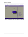
1
MANO840 ® Intel Bay Trail SoC CPU Mini ITX Motherboard User’s Manual Disclaimers This manual has been carefully checked and believed to contain accurate information. Axiomtek Co., Ltd. assumes no responsibility for any infringements of patents or any third party’s rights, and any liability arising from such use. Axiomtek does not warrant or assume any legal liability or responsibility for the accuracy, completeness or usefulness of any information in this document. Axiomtek does not make any commitment to update the information in this manual. Axiomtek reserves the right to change or revise this document and/or product at any time without notice. No part of this document may be reproduced, stored in a retrieval system, or transmitted, in any form or by any means, electronic, mechanical, photocopying, recording, or otherwise, without the prior written permission of Axiomtek Co., Ltd. CAUTION If you replace wrong batteries, it causes the danger of explosion. It is recommended by the manufacturer that you follow the manufacturer’s instructions to only replace the same or equivalent type of battery, and dispose of used ones. Copyright 2014 Axiomtek Co., Ltd. All Rights Reserved August 2014, Version A1 Printed in Taiwan ii ESD Precautions Computer boards have integrated circuits sensitive to static electricity. To prevent chipsets from electrostatic discharge damage, please take care of the following jobs with precautions: Do not remove boards or integrated circuits from their anti-static packaging until you are ready to install them. Before holding the board or integrated circuit, touch an unpainted portion of the system unit chassis for a few seconds. It discharges static electricity from your body. Wear a wrist-grounding strap, available from most electronic component stores, when handling boards and components. Trademarks Acknowledgments Axiomtek is a trademark of Axiomtek Co., Ltd. ® Windows is a trademark of Microsoft Corporation. AMI is a trademark of American Megatrend Inc. IBM, PC/AT, PS/2, VGA are trademarks of International Business Machines Corporation. ® Intel is a trademark of Intel Corporation. Realtek is a trademark of Realtek Semi-Conductor Co., Ltd. Other brand names and trademarks are the properties and registered brands of their respective owners. iii Conventions Used in This Manual To make sure that you perform certain tasks properly, take note of the following symbols used throughout this manual. Information to prevent injury to yourself when trying to complete a task. Warning Information to prevent damage to the components when trying to complete a task. Caution Instructions that you MUST follow to complete a task. Important Tips and additional information to help you complete a task. Note iv Table of Contents Disclaimers ..................................................................................................... ii ESD Precautions ........................................................................................... iii Conventions Used in This Manual............................................................... iv Chapter 1 Introduction ............................................. 1 1.1 Features ............................................................................................... 2 1.2 Specifications ...................................................................................... 2 1.3 Utilities Supported .............................................................................. 3 1.4 Block Diagram ..................................................................................... 4 Chapter 2 Board and Pin Assignments .................... 5 2.1 Board Layout ....................................................................................... 5 2.2 Rear Panel I/O ...................................................................................... 5 2.3 Jumper Settings .................................................................................. 6 2.3.1 2.3.2 2.3.3 2.3.4 2.4 Connectors .......................................................................................... 9 2.4.1 2.4.2 2.4.3 2.4.4 2.4.5 2.4.6 2.4.7 2.4.8 2.4.9 2.4.10 2.4.11 2.4.12 2.4.13 2.4.14 2.4.15 Chapter 3 3.1 Clear CMOS (CLR_CMOS) ........................................................................ 7 VCON Voltage Select (VCON) .................................................................... 7 LVDS Backlight Power Select (LCD_PWR1) .............................................. 7 COM RI/+5V/+12V Select (COM_RI) .......................................................... 8 Rear Panel Connectors ............................................................................. 10 FAN Connectors (CPU_FAN and SYS_FAN) ........................................... 10 Digital I/O Connector (DIO) ........................................................................ 11 Front Panel Connector (F_PANEL) ............................................................ 11 ATX Power Connector (ATX12V) .............................................................. 12 Audio Connector (F_AUDIO) .................................................................... 12 LVDS Connector (LVDS) ........................................................................... 13 LCD Inverter Connector (LVDSPW) .......................................................... 14 SATA Power Connector (SATA_PWR) ...................................................... 14 Speaker Connector (SPKR) ...................................................................... 15 SATA Connectors (SATA1 and SATA2) ..................................................... 15 USB 2.0 Connector (F_USB) .................................................................... 16 USB 3.0 Connector (USB3.0) ................................................................... 16 COM Connector (JCOM3-1) ..................................................................... 17 Parallel Port Connector (LPT) ................................................................... 17 Hardware Installation ........................... 19 Motherboard Overview ..................................................................... 19 v 3.1.1 3.1.2 3.2 System Memory ................................................................................. 20 3.2.1 3.2.2 3.3.3 3.2.4 3.3 Placement Direction .................................................................................. 19 Screw Holes .............................................................................................. 19 Overview ................................................................................................... 20 Memory Configurations ............................................................................. 21 Installing a SO-DIMM ................................................................................ 21 Removing a SO-DIMM .............................................................................. 23 Expansion Card ................................................................................. 23 3.3.1 3.3.2 3.3.3 3.3.4 Chapter 4 Installing an Expansion Card..................................................................... 23 Configuring an Expansion Card ................................................................ 24 PCI-Express x1 Slot (PCIE) ...................................................................... 24 PCI-Express Mini Card Connector ............................................................ 24 Hardware Description ........................... 25 4.1 Microprocessors ............................................................................... 25 4.2 BIOS ................................................................................................... 25 4.3 System Memory ................................................................................. 25 4.4 I/O Port Address Map ........................................................................ 26 4.5 Interrupt Controller (IRQ) Map ......................................................... 28 4.6 Memory Map ...................................................................................... 35 Chapter 5 AMI BIOS Setup Utility .......................... 37 5.1 Starting ............................................................................................... 37 5.2 Navigation Keys ................................................................................ 37 5.3 Main Menu.......................................................................................... 39 5.4 Advanced Menu ................................................................................. 40 5.5 Chipset Menu ..................................................................................... 52 5.6 Boot Menu.......................................................................................... 55 5.7 Security Menu .................................................................................... 57 5.8 Save & Exit Menu .............................................................................. 58 vi MANO840 Mini ITX Motherboard Chapter 1 Introduction ® MANO840 is designed with Intel Celeron™ J1900 SoC for industrial applications that request ® performance computing and reliable stability. The motherboard has onboard CPU Intel Celeron™ J1900 Quad core 2.42GHz. MANO840 has rich I/O connectivity with PS/2, COM port, Dual LAN, USB port and audio jack integrated in a standard 170mm x 170mm Mini ITX form factor. These motherboards also support dual display for LVDS, HDMI and VGA. MANO840 also comes with plenty of connectivity and expansion options. Vertical USB 3.0 port, 8-bit GPIO, two SATA 2.0 ports, PCI-Express Mini Card and PCI-Express x1 slot enable easy integration. 1000/100/10Mbps Ethernet port is also available to deliver high speed networking. Introduction 1 MANO840 Mini ITX Motherboard 1.1 Features ® Intel Celeron™ J1900 SoC processor 1 DDR3L 1333/1066MHz up to 8GB 1 PCI-Express x1 slot 1 USB 3.0 and 5 USB 2.0 supported 2 SATA 2.0 supported 6 COM ports supported Dual view display 1.2 Specifications CPU ® Intel Celeron™ J1900 SoC processor. BIOS AMI 64Mb SPI ROM. System Memory One 204-pin DDR3L SO-DIMM socket. Maximum up to 8GB DDR3L 1333/1066MHz memory. Onboard Multi I/O Serial ports: Six RS-232 ports and one RS-232 port with 5V/12V power. One PS/2 keyboard/mouse. Serial ATA Two SATA 2.0 ports (3Gb/s performance). USB Interface One USB 3.0 port. Five USB 2.0 ports. Display One VGA - up to 2560x1600 . One HDMI - up to 1920x1080 . One LVDS – up to 1920x1200 . Ethernet LAN1 - 1000/100/10Mbps with Realtek RTL8111G GbE LAN. LAN2 - 1000/100/10Mbps with Realtek RTL8111G GbE LAN. Audio HD audio compliant via Realtek ALC269. MIC-in and line-out. Digital I/O Eight channels. Expansion Interface One PCI-Express x1 slot. One PCI-Express Mini Card(support mSATA, share SATA Signal with SATA2 Conn) 2 Introduction MANO840 Mini ITX Motherboard Hardware Monitoring Detect CPU/system temperature, voltage and fan speed. Watchdog Timer 1~255 seconds; up to 255 levels. Power Management ACPI (Advanced Configuration and Power Interface). Form Factor Mini ITX form factor. All specifications and images are subject to change without notice. Note 1.3 Utilities Supported Chipset driver Ethernet driver Graphics driver Audio driver Introduction 3 MANO840 Mini ITX Motherboard 1.4 4 Block Diagram Introduction MANO840 Mini ITX Motherboard Chapter 2 Board and Pin Assignments 2.1 Board Layout 2.2 Rear Panel I/O Board and Pin Assignments 5 MANO840 Mini ITX Motherboard 2.3 Jumper Settings Jumper is a small component consisting of jumper clip and jumper pins. Install jumper clip on 2 jumper pins to close. And remove jumper clip from 2 jumper pins to open. The following illustration shows how to set up jumper. Before applying power to MANO840 Series, please make sure all of the jumpers are in factory default position. Below you can find a summary table and onboard default settings. Once the default jumper setting needs to be changed, please do it under power-off condition. Note Jumper Description Setting CLR_CMOS Clear CMOS Default: Normal Operation 1-2 Close VCON VCON Voltage Select Default: Ground 2-3 Close LCD_PWR1 LVDS Panel Power Select Default: +5V 1-2 Close COM_RI COM3 RI/+5V/+12V Select Default: RI 3-4 Close 6 Board and Pin Assignments MANO840 Mini ITX Motherboard 2.3.1 Clear CMOS (CLR_CMOS) This jumper allows you to clear the Real Time Clock (RTC) RAM in CMOS. You can clear the CMOS memory of date, time, and system setup parameters by erasing the CMOS RTC RAM data. The onboard button cell battery powers the RAM data in CMOS, which includes system setup information such as system passwords. To erase the RTC RAM: 1. Turn OFF the computer and unplug the power cord. 2. Remove the onboard battery. 3. Move the jumper clip from pins 1-2 (default) to pins 2-3. Keep the clip on pins 2-3 for about 5~10 seconds, then move the clip back to pins 1-2. 4. Re-install the battery. 5. Plug the power cord and turn ON the computer. 6. Hold down the <Del> key during the boot process and enter BIOS setup to re-enter data. Except when clearing the RTC RAM, never remove the clip on this jumper default position. Removing the clip will cause system boot failure! Caution Function Setting Normal operation (Default) Clear CMOS 1-2 close 2-3 close You do not need to clear the RTC when the system hangs due to overclocking. For system failure due to overclocking, use the C.P.R. (CPU Parameter Recall) feature. Shut down and reboot the system so the BIOS can automatically reset parameter settings to default values. Note 2.3.2 VCON Voltage Select (VCON) This jumper allows you to select the panel type of LVDS panel. Function Setting +3.3 GND(Default) 1-2 close 2-3 close 2.3.3 LVDS Panel Power Select (LCD_PWR1) This jumper allows you to select the panel power mode of LVDS panel. Function Setting +5V (Default) +3.3V 1-2 close 2-3 close Board and Pin Assignments 7 MANO840 Mini ITX Motherboard 2.3.4 COM3 RI/+5V/+12V Select (COM_RI) This jumper allows you to select the power mode of COM3 port. 8 Function Setting +12V RI (Default) +5V 1-2 close 3-4 close 5-6 close Board and Pin Assignments MANO840 Mini ITX Motherboard 2.4 Connectors Signals go to other parts of the system through connectors. Loose or improper connection might cause problems, please make sure all connectors are properly and firmly connected. Here is a summary table which shows connectors on the hardware. Connector Description DC_IN 12V DC Inlet PSKBM PS/2 Keyboard and Mouse Mini Din HDMI HDMI Port VGA VGA Port USBLAN1 LAN1 and 2 USB 2.0 Port USBLAN2 LAN2 and 2 USB 2.0 Port COM COM1 and COM2 Ports AUDIO Audio Jack CPU_FAN CPU Fan Connector SYS_FAN System Fan Connector DIO Digital I/O Connector F_PANEL Front Panel Connector ATX12V ATX Power Connector F_AUDIO Audio Connector LVDS LVDS Connector LVDSPW LCD Inverter Connector SATA_PWR SATA Power Connector SPKR Speaker Connector SATA1~SATA2 SATA Connectors F_USB USB 2.0 Connector USB3.0 USB 3.0 Connector JCOM3-1 COM3~COM6 Connector LPT Parallel Port Connector PCIE PCI-Express x1 Slot MPE PCI-Express Mini Card Connector DIMM 204-pin DDR3L SO-DIMM Socket Board and Pin Assignments 9 MANO840 Mini ITX Motherboard 2.4.1 1. 2. 3. 4. 5. 6. 7. 8. 9. 10. 11. Rear Panel Connectors DC_IN. This inlet is for 12V DC inlet. PS/2 mouse port (green). This port is for a PS/2 mouse. PS/2 keyboard port (purple). This port is for a PS/2 keyboard. VGA port. This 15-pin VGA port connects to a VGA monitor. HDMI port. This 19-pin HDMI 1.3 port connects to a HDMI monitor. LAN (RJ-45) ports. Each of these ports allows Gigabit connection to a Local Area Network (LAN) through a network hub. Refer to the table below for the LAN port LED indications. ACT/LINK LED Status Description Status OFF Yellow Blinking OFF Orange Green No link Link Data activity SPEED LED Description 10Mbps connection 100Mbps connection 1Gbps connection USB 2.0 ports 1~4. These four 4-pin Universal Serial Bus (USB) ports are available for connecting USB 2.0 devices. Serial connector. This 9-pin COM1 port is for serial devices. Serial connector. This 9-pin COM2 port is for serial devices. Line-out port (Green). This port connects a headphone or a speaker. Microphone port (pink). This port connects a microphone. 2.4.2 FAN Connectors (CPU_FAN and SYS_FAN) The fan connectors support cooling fans of 280mA (3.36 W max.) at 4800rpm or a total of 1A~2.22A (26.64W max.) at +12V. Connect the fan cables to the fan connectors on the motherboard, making sure that the black wire of each cable matches the ground pin of the connector. CPU fan interface is available through CPU_FAN, see table below. 10 Pin Signal 1 2 3 4 GND +12V SENSE GPO Board and Pin Assignments MANO840 Mini ITX Motherboard System fan interface is available through SYS_FAN, see table below. Pin Signal 1 2 3 4 GND +12V SENSE GPO Do not forget to connect the fan cables to the fan connectors. Insufficient air flow inside the system may damage the motherboard components. These are not jumpers! DO NOT place jumper caps on the fan connectors. Caution 2.4.3 Digital I/O Connector (DIO) This connector is for GPIO function. Pin Signal Pin Signal 2 1 3 5 7 9 GPIO_S0_SC17_DI GPIO_S0_SC18_DI GPIO_S0_SC19_DI GPIO_S0_SC20_DI 5VSB 2 4 6 8 10 GPIO_S0_SC21_DO GPIO_S0_SC22_DO GPIO_S0_SC23_DO GPIO_S0_SC24_DO GND 1 2.4.4 Front Panel Connector (F_PANEL) This connector is for a chassis-mounted front panel I/O module that supports power on/ reset switch and HDD/ power LED indicator. The functions are described as follows. Pin Signal Pin Signal 1 3 5 7 9 HDDLED+ HDDLEDGND RESET NC 2 4 6 8 POWERLED+POWERLEDPWSWITCH GND 2 1 ATX Power Button/Soft-off Button (Pin 6-8 PWRBT) This 2-pin connector is for the system power button. Pressing the power button turns the system on or puts the system in sleep or soft-off mode depending on the BIOS settings. Pressing the power switch and holding it for more than four seconds while the system is ON turns the system OFF. Reset Button (Pin 5-7 SYS_RST) This 2-pin connector is for the chassis-mounted reset button for system reboot without turning off the system power. Power LED (Pin 2-4 PWRLED) This 2-pin connector is for the system power LED. Connect the chassis power LED cable to this connector. The system power LED lights up when you turn on the system power, and blinks when the system is in sleep mode. Board and Pin Assignments 11 MANO840 Mini ITX Motherboard Hard Disk Drive Activity LED (Pin 1-3 HDLED) This 2-pin connector is for the HDD Activity LED. Connect the HDD Activity LED cable to this connector. The IDE LED lights up or flashes when data is read from or written to the HDD. 2.4.5 ATX Power Connector (ATX12V) The connector is for ATX power supply plugs. The power supply plugs are designed to fit these connectors in only one orientation. Find the proper orientation and push down firmly until the connectors completely fit. Pin Signal Pin Signal 1 2 GND GND 3 4 +12V +12V Note 2.4.6 2 1 Use of a PSU with a higher power output is recommended when configuring a system with more power-consuming devices. The system may become unstable or may not boot up if the power is inadequate. Make sure that your power supply unit (PSU) can provide at least the minimum power required by your system. Audio Connector (F_AUDIO) This connector is for a chassis-mounted front panel audio I/O module that supports either HD Audio or legacy AC ‘97 (optional) audio standard. Connect one end of the front panel audio I/O module cable to this connector. Pin Signal Pin Signal 1 3 5 7 9 MIC2_L MIC2_R HPOUT-R AUGND HPOUT-L 2 4 6 8 10 AUGND FP_AUD_DETECT MIC2-JD NC HPOUT-JD Important 12 1 For motherboards with the optional HD Audio feature, we recommend that you connect a high-definition front panel audio module to this connector to avail of the motherboard’s high-definition audio capability. Board and Pin Assignments MANO840 Mini ITX Motherboard 2.4.7 LVDS Connector (LVDS) The connector is for 24-bit dual channel LVDS panel. Pin Signal Pin Signal 1 3 5 7 9 11 13 15 17 19 21 23 25 27 29 31 33 35 37 39 LCD_VDD GND LCD_VDD TXO0TXO0+ GND TXO1TXO1+ GND TXO2TXO2+ GND TXOCTXOC+ GND DDC_CLK GND TXO3TXO3+ BKLT_EN 2 4 6 8 10 12 14 16 18 20 22 24 26 28 30 32 34 36 38 40 LCD_VDD GND LCD_VDD TXE0TXE0+ GND TXE1TXE1+ GND TXE2TXE2+ GND TXECTXEC+ GND DDC_DATA GND TXE3TXE3+ VCON Board and Pin Assignments 13 MANO840 Mini ITX Motherboard 2.4.8 LCD Inverter Connector (LVDSPW) The connector is for the control of internal LVDS brightness. Pin Signal 1 2 3 4 5 +12V GND ENBKL PWM +5V 1 Signal Description: PWM For inverter with adjustable backlight function, it is possible to control the LCD brightness through the PWM signal. Vadj = 0.75V ~ 4.25V (Recommended: 4.7KΩ, >1/16W) ENBKL LCD backlight ON/OFF control signal. 2.4.9 SATA Power Connector (SATA_PWR) This connector supports SATA device power. 14 Pin Signal 1 2 3 4 5 6 7 8 9 10 11 12 13 14 15 3.3V 3.3V 3.3V GND GND GND 5V 5V 5V GND GND GND 12V 12V 12V 1 Board and Pin Assignments MANO840 Mini ITX Motherboard 2.4.10 Speaker Connector (SPKR) This connector supports speaker signal. Pin Signal 1 2 3 4 SPK-LLSPK-LL+ SPK-RRSPK-RR+ 2.4.11 1 SATA Connectors (SATA1 and SATA2) These connectors support SATA 2.0 and are for the Serial ATA signal cables for Serial ATA hard disk drives. Pin Signal 1 2 3 4 5 6 7 GND SATA_TXP2 SATA_TXN2 GND SATA_RXN2 SATA_RXP2 GND Board and Pin Assignments SATA2 SATA1 15 MANO840 Mini ITX Motherboard 2.4.12 USB 2.0 Connector (F_USB) This connector is for USB 2.0 port. Connect the optional USB module cable to this connector then install the module to a slot opening at the back of the system chassis. This USB connector complies with USB 2.0 specification that supports up to 480Mbps connection speed. Pin Signal 1 2 3 4 5 PS2_USB USB_DN2_CMK USB_DP2_CMK GND NC 2.4.13 1 USB 3.0 Connector (USB3.0) This connector provides USB Rev. 3.0 supporting transmission rate up to 5Gbps and fuse protect. 16 Pin Signal 1 2 3 4 5 6 7 8 9 VCC -DATA1 +DATA1 GND -SRX1 +SRX1 GND -STX1 +STX1 Board and Pin Assignments MANO840 Mini ITX Motherboard 2.4.14 COM Connector (JCOM3-1) This connector is for four serial ports (COM3~COM6). Connect the serial port module cable to this connector then install the module to a slot opening at the back of the system chassis. Pin Signal Pin Signal 1 3 5 7 9 11 13 15 17 19 21 23 25 27 29 31 33 35 37 39 COM3_DCD# COM3_RXD COM3_TXD COM3_DTR# GND COM4_DCD# COM4_RXD COM4_TXD COM4_DTR# GND COM5_DCD# COM5_RXD COM5_TXD COM5_DTR# GND JDDCD6# JRRXD6 JTTXD6 JDDTR6# GND 2 4 6 8 10 12 14 16 18 20 22 24 26 28 30 32 34 36 38 40 COM3_DSR# COM3_RTS# COM3_CTS# RI3xPOWER GND COM4_DSR# COM4_RTS# COM4_CTS# COM4_RI# GND COM5_DSR# COM5_RTS# COM5_CTS# COM5_RI# GND COM6_DSR# COM6_RTS# COM6_CTS# COM6_RI# GND 2.4.15 1 Parallel Port Connector (LPT) This connector is for parallel port function. Pin Signal Pin Signal 1 2 3 4 5 6 7 8 9 10 11 12 13 -NSTB PD0 PD1 PD2 PD3 PD4 PD5 PD6 PD7 ACK_L BUSY PE SLCT 14 15 16 17 18 19 20 21 22 23 24 25 26 -AFD -ERROR -INIT -SLIN GND GND GND GND GND GND GND GND NC Board and Pin Assignments 14 1 17 MANO840 Mini ITX Motherboard This page is intentionally left blank. 18 Board and Pin Assignments MANO840 Mini ITX Motherboard Chapter 3 Hardware Installation Take note of the following precautions before you install motherboard components or change any motherboard settings. Caution 3.1 Unplug the power cord from the wall socket before touching any component. Use a grounded wrist strap or touch a safely grounded object or a metal object, such as the power supply case, before handling components to avoid damaging them due to static electricity. Hold components by the edges to avoid touching the ICs on them. Whenever you uninstall any component, place it on a grounded anti-static pad or in the bag that came with the component. Before you install or remove any component, ensure that the ATX power supply is switched off or the power cord is detached from the power supply. Failure to do so may cause severe damage to the motherboard, peripherals, and/or components. Motherboard Overview Before you install the motherboard, study the configuration of your chassis to ensure that the motherboard fits into it. Refer to the chassis documentation before installing the motherboard. Warning Make sure to unplug the power cord before installing or removing the motherboard. Failure to do so can cause you physical injury and damage motherboard components. 3.1.1 Placement Direction When installing the motherboard, make sure that you place it into the chassis in the correct orientation. The edge with external ports goes to the rear part of the chassis as indicated in the image below. 3.1.2 Screw Holes Place four (4) screws into the holes indicated by circles to secure the motherboard to the chassis. Do not over-tighten the screws! Doing so can damage the motherboard. Caution Hardware Installation 19 MANO840 Mini ITX Motherboard Place this side towards the rear of the chassis. 3.2 System Memory 3.2.1 Overview The motherboard comes with one 204-pin Double Data Rate 3 Low voltage (DDR3L) Small Outline Dual Inline Memory Modules (SO-DIMM) socket. A DDR3L module has the same physical dimensions as a DDR SO-DIMM but has a 204-pin footprint compared to the 204-pin DDR2 DIMM. DDR3L DIMMs are notched differently to prevent installation on a DDR2 DIMM socket. The following figure illustrates the location of the sockets: 204-pin DDR3L SO-DIMM socket 20 Channel Socket Channel A DIMM Hardware Installation MANO840 Mini ITX Motherboard 3.2.2 Memory Configurations You may install 1GB, 2GB, 4GB and 8GB non-ECC DDR3L SO-DIMM into the SO-DIMM socket using the memory configurations in this section. Important 3.3.3 1. If you installed over 4GB memory module, the system may detect less than 3GB of total memory because of address space allocation for other critical functions. This limitation applies to Windows 32-bit version operating system since it does not support PAE (Physical Address Extension) mode. If you install Windows 32-bit version operating system, we recommend that you install less than 3GB of total memory. Due to CPU limitation, SO-DIMM modules with 128Mb memory chips or double-sided x16 memory chips are not supported in this motherboard. Installing a SO-DIMM Unlock a SO-DIMM socket by pressing the retaining clips outward. Hardware Installation 21 MANO840 Mini ITX Motherboard 2. Align a SO-DIMM on the socket such that the notch on the SO-DIMM matches the break on the socket. DDR3L SO-DIMM notch Unlocked retaining clip 3. Firmly insert the SO-DIMM into the socket until the retaining clips snap back in place and the SO-DIMM is properly seated. Locked retaining clip Important Caution 22 A DDR3L SO-DIMM is keyed with a notch so that it fits in only one direction. DO NOT force a SO-DIMM into a socket to avoid damaging the SO-DIMM. The DDR3L SO-DIMM socket does not support DDR2 SO-DIMM. DO NOT install DDR2 SO-DIMM to the DDR3L SO-DIMM socket. Make sure to unplug the power supply before adding or removing SO-DIMM or other system components. Failure to do so may cause severe damage to both the motherboard and the components. Hardware Installation MANO840 Mini ITX Motherboard 3.2.4 1. 2. Removing a SO-DIMM Simultaneously press the retaining clips downward to unlock the SO-DIMM. Remove the SO-DIMM from the socket. Unlocked retaining clip Note 3.3 Support the SO-DIMM lightly with your fingers when pressing the retaining clips. The SO-DIMM might get damaged when it flips out with extra force. Expansion Card In the future, you may need to install expansion cards. The following sub-sections describe the slots and the expansion cards that they support. Make sure to unplug the power cord before adding or removing expansion cards. Failure to do so may cause you physical injury and damage motherboard components. Warning 3.3.1 1. 2. 3. 4. 5. 6. Installing an Expansion Card Before installing the expansion card, read the documentation that came with it and make the necessary hardware settings for the card. Remove the system unit cover (if your motherboard is already installed in a chassis). Remove the bracket opposite the slot that you intend to use. Keep the screw for later use. Align the card connector with the slot and press firmly until the card is completely seated on the slot. Secure the card to the chassis with the screw you removed earlier. Replace the system cover. Hardware Installation 23 MANO840 Mini ITX Motherboard 3.3.2 Configuring an Expansion Card After installing the expansion card, configure it by adjusting the software settings. 1. Turn on the system and change the necessary BIOS settings, if any. See Chapter 5 for information on BIOS setup. 2. Assign an IRQ to the card if needed. 3. Install the software drivers for the expansion card. 3.3.3 PCI-Express x1 Slot (PCIE) This motherboard supports one PCI-Express x1. The following figure shows a PCI-Express x1 card installed on the PCI-Express x1 slot. 3.3.4 PCI-Express Mini Card Connector This motherboard has one PCI-Express Mini Card slot which supports SATA/USB2.0/ PCIe signal. The following figure shows a PCI-Express Mini Card installed on this connector. Note: SATA2 Conn and mSATA share the same SATA signal, if mSATA is connected, SATA2 Conn will not be available, since mSATA is the first priority. 24 Hardware Installation MANO840 Mini ITX Motherboard Chapter 4 Hardware Description 4.1 Microprocessors ® TM The MANO840 Series supports Intel Celeron J1900 SoC processor, which enable your ® ® system to operate under Windows 7, Windows 8 and Linux environments. The system performance depends on the microprocessor. Make sure all correct settings are arranged for your installed microprocessor to prevent the CPU from damages. 4.2 BIOS The MANO840 Series uses AMI Plug and Play BIOS with a single 64Mb SPI Flash. 4.3 System Memory The MANO840 Series supports one 204-pin DDR3L SO-DIMM socket for maximum memory capacity up to 8GB DDR3L SDRAMs. The memory module comes in sizes of 1GB, 2GB, 4GB and 8GB. Hardware Description 25 MANO840 Mini ITX Motherboard 4.4 I/O Port Address Map ® TM J1900 SoC processor communicates via I/O ports. Total 1KB port The Intel Celeron addresses are available for assigning to other devices via I/O expansion cards. 26 Hardware Description MANO840 Mini ITX Motherboard Hardware Description 27 MANO840 Mini ITX Motherboard 4.5 Interrupt Controller (IRQ) Map The interrupt controller (IRQ) mapping list is shown as follows: 28 Hardware Description MANO840 Mini ITX Motherboard Hardware Description 29 MANO840 Mini ITX Motherboard 30 Hardware Description MANO840 Mini ITX Motherboard Hardware Description 31 MANO840 Mini ITX Motherboard 32 Hardware Description MANO840 Mini ITX Motherboard Hardware Description 33 MANO840 Mini ITX Motherboard 34 Hardware Description MANO840 Mini ITX Motherboard 4.6 Memory Map The memory mapping list is shown as follows: Hardware Description 35 MANO840 Mini ITX Motherboard This page is intentionally left blank. 36 Hardware Description MANO840 Mini ITX Motherboard Chapter 5 AMI BIOS Setup Utility The AMI UEFI BIOS provides users with a built-in setup program to modify basic system configuration. All configured parameters are stored in a flash chip to save the setup information whenever the power is turned off. This chapter provides users with detailed description about how to set up basic system configuration through the AMI BIOS setup utility. 5.1 Starting To enter the setup screens, follow the steps below: 1. 2. Turn on the computer and press the <Del> key immediately. After you press the <Del> key, the main BIOS setup menu displays. You can access the other setup screens from the main BIOS setup menu, such as the Advanced and Chipset menus. Note If your computer cannot boot after making and saving system changes with BIOS setup, you can restore BIOS optimal defaults by setting CLR_CMOS (see section 2.3.1). It is strongly recommended that you should avoid changing the chipset’s defaults. Both AMI and your system manufacturer have carefully set up these defaults that provide the best performance and reliability. 5.2 Navigation Keys The BIOS setup/utility uses a key-based navigation system called hot keys. Most of the BIOS setup utility hot keys can be used at any time during the setup navigation process. These keys include <F1>, <F2>, <Enter>, <ESC>, <Arrow> keys, and so on. Some of the navigation keys differ from one screen to another. Note AMI BIOS Setup Utility 37 MANO840 Mini ITX Motherboard Hot Keys Description Left/Right The Left and Right <Arrow> keys allow you to select a setup screen. Up/Down The Up and Down <Arrow> keys allow you to select a setup screen or sub-screen. Enter The <Enter> key allows you to display or change the setup option listed for a particular setup item. The <Enter> key can also allow you to display the setup sub- screens. +− Plus/Minus The Plus and Minus <Arrow> keys allow you to change the field value of a particular setup item. F1 The <F1> key allows you to display the General Help screen. F2 The <F2> key allows you to Load Previous Values. F3 The <F3> key allows you to Load Optimized Defaults. F4 The <F4> key allows you to save any changes you have made and exit Setup. Press the <F4> key to save your changes. Esc The <Esc> key allows you to discard any changes you have made and exit the Setup. Press the <Esc> key to exit the setup without saving your changes. 38 AMI BIOS Setup Utility MANO840 Mini ITX Motherboard 5.3 Main Menu When you first enter the setup utility, you will enter the Main setup screen. You can always return to the Main setup screen by selecting the Main tab. System Time/Date can be set up as described below. The Main BIOS setup screen is shown below. BIOS Information Display the auto-detected BIOS information. System Date/Time Use this option to change the system time and date. Highlight System Time or System Date using the <Arrow> keys. Enter new values through the keyboard. Press the <Tab> key or the <Arrow> keys to move between fields. The date must be entered in MM/DD/YY format. The time is entered in HH:MM:SS format. AMI BIOS Setup Utility 39 MANO840 Mini ITX Motherboard 5.4 Advanced Menu Launch PXE OpROM Enable or disable the boot ROM function of the onboard LAN chip when the system boots up. The Advanced menu also allows users to set configuration of the CPU and other system devices. You can select any of the items in the left frame of the screen to go to the sub menus: ► ► ► ► ► ► ► ► ► ► ► ACPI Settings RTC Wake Settings CPU Configuration SATA Configuration Intel IGD SWSCI OpRegion USB Configuration Super IO Configuration H/W Monitor TXE Configuration Trusted Computing DIO Configuration For items marked with “”, please press <Enter> for more options. Take caution when changing the settings of the Advanced menu items. Incorrect field values can cause the system to malfunction. Caution 40 AMI BIOS Setup Utility MANO840 Mini ITX Motherboard ACPI Settings You can use this screen to select options for the ACPI configuration, and change the value of the selected option. A description of the selected item appears on the right side of the screen. ACPI Sleep State Select the highest ACPI sleep state the system will enter when the suspend button is pressed. Configuration options are Suspend Disabled and S3 (Suspend to RAM). AMI BIOS Setup Utility 41 MANO840 Mini ITX Motherboard RTC Wake Settings Wake system with Fixed Time Enable or disable system wake on alarm even. When enabled, system will wake upon the hr/min/sec specified. 42 AMI BIOS Setup Utility MANO840 Mini ITX Motherboard CPU Configuration This screen shows the CPU information. AMI BIOS Setup Utility 43 MANO840 Mini ITX Motherboard SATA Configuration In this Configuration menu, you can see the currently installed hardware in the SATA ports. During system boot up, the BIOS automatically detects the presence of SATA devices. SATA Mode Determine how SATA controller(s) operate. Operation mode options are Disabled, IDE Mode and AHCI Mode. 44 AMI BIOS Setup Utility MANO840 Mini ITX Motherboard Intel IGD SWSCI OpRegion LCD Panel Type This option allows you to select the type of LCD panel connected to the motherboard’s built-in graphics chip. AMI BIOS Setup Utility 45 MANO840 Mini ITX Motherboard USB Configuration You can use this screen to select options for the USB Configuration, and change the value of the selected option. A description of the selected item appears on the right side of the screen. USB Devices Display all detected USB devices. Legacy USB Support Enable or disable support for USB device on legacy operating system. The default setting is Enabled. Auto option disables legacy support if no USB devices are connected. Disable option will keep USB devices available only for EFI applications. XHCI Mode Enable option allow XHCI mode support. Disable option will keep XHCI mode disable. Auto option will auto detect which mode is better. Smart auto option will auto detect the suitable mode for device plugged. 46 AMI BIOS Setup Utility MANO840 Mini ITX Motherboard Super IO Configuration You can use this screen to select options for the Super IO Configuration, and change the value of the selected option. A description of the selected item appears on the right side of the screen. For items marked with “”, please press <Enter> for more options. Serial Port 1~6 Configuration Set parameters of serial port 1 (COM1) ~ serial port 6 (COM6). Change settings Select an optimal setting for super IO device. Parallel Port Configuration Set parameters of LPT port. Change settings Select an optimal setting for super IO device. Restore AC Power Loss Set the state after power loss. Watch Dog Timer Select watchdog count mode second/minute. Watch Dog Timer Time Out Value Timer will start to count from end of POST. 00 - Time out Disable. AMI BIOS Setup Utility 47 MANO840 Mini ITX Motherboard H/W Monitor Use this screen for Smart Fan configuration and hardware health status monitoring. This screen displays the temperature of system and CPU, cooling fan speed in RPM and system voltages (CPU VCORE, 5V, 5VSB, 12V and 3.3V). Smart Fan Function Select CPU fan mode. When this feature is set to automatic the CPU’s fan speed will rotate according to the CPU’s temperature; the higher the temperature, the faster the speed of rotation. Smart Fan Mode Configuration Select Manual mode or Thermal Cruise mode. 48 AMI BIOS Setup Utility MANO840 Mini ITX Motherboard TXE Configuration TXE Enable or disable TXE firmware. AMI BIOS Setup Utility 49 MANO840 Mini ITX Motherboard Trusted Computing Security Device Support Enable or disable BIOS support for security device. 50 AMI BIOS Setup Utility MANO840 Mini ITX Motherboard DIO Configuration Allow user to check digital input 1~4 port state and set digital output 5~8 port setting. EUP Function AMI BIOS Setup Utility 51 MANO840 Mini ITX Motherboard 5.5 Chipset Menu The Chipset menu allows users to change the advanced chipset settings. You can select any of the items in the left frame of the screen to go to the sub menus: ► North Bridge ► South Bridge For items marked with “”, please press <Enter> for more options. 52 AMI BIOS Setup Utility MANO840 Mini ITX Motherboard North Bridge This screen is for North Bridge configuration. DVMT Total Gfx Mem When set to Max Mode, the graphics driver will reserve a Max. of system memory as graphics memory, according to system and graphics requirement DVMT Pre-Allocated Select DVMT pre-allocated graphics memory size used by the internal graphics device (IGD). Initiate Graphic Adapter Set initial graphic adapter. AMI BIOS Setup Utility 53 MANO840 Mini ITX Motherboard South Bridge LAN 1/2 Controller Enable or disable onboard LAN1/LAN2 controller. Azalia HD Audio Enable or disable onboard HD Audio controller. Azalia Internal HDMI Codec Enable or disable onboard Audio internal HDMI controller. Resume from LAN1/2 Enable or disable resume from LAN1/LAN2 function. Resume from WAK# / RING Enable or disable COM port WAK#/RING function. 54 AMI BIOS Setup Utility MANO840 Mini ITX Motherboard 5.6 Boot Menu The Boot menu allows users to change boot options of the system. Operation System Select Select which OS would be installed. Configuration options are Windows 7 or other OS, Windows 8.x, Windows 8.x with CSM and Manual. Quiet Boot Enable or disable Quiet Boot mode. Fast Boot Enable or disable Fast Boot mode. Setup Prompt Timeout Increasing the value will make the POST take longer; the default setting is 1 second. Bootup NumLock State Select the keyboard number lock status. AMI BIOS Setup Utility 55 MANO840 Mini ITX Motherboard Boot Mode Select This item could be set to Legacy or UEFI. Set Boot Priority Set boot device priority by BIOS setting. 56 AMI BIOS Setup Utility MANO840 Mini ITX Motherboard 5.7 Security Menu The Security menu allows users to change the security settings for the system. Administrator Password Set setup administrator password. User Password Set user password. AMI BIOS Setup Utility 57 MANO840 Mini ITX Motherboard 5.8 Save & Exit Menu The Save & Exit menu allows users to load your system configuration with optimal or fail-safe default values. Save Changes and Exit Exit system setup after saving the changes. Discard Changes and Exit Exit system setup without saving the changes. Restore Defaults Restore/load default values for all the setup option. 58 AMI BIOS Setup Utility