1
Stephen Parascandolo
Brunel University
BEng Computer Systems Engineering
Student ID: 9900239/1
Supervisor: Dr Ian Dear
Tutor: Mr Peter VanSanten
Model Railway
Computer Control Centre
Final Year Project Report
May 2003
Volume 1 – Main Report, References and Appendixes A – F
Contents
Model Railway Computer Control Centre
By Stephen Parascandolo
VOLUME 1
Contents ..........................................................................................................1
Introduction.....................................................................................................7
Model Railway Computer Control Centre ...................................................7
1.1 About this Report.............................................................................8
1.2 Aims and Objectives .......................................................................9
[1] Provide Realistic Signalling on the Model Railway...................9
[2] Provide a User Interface similar to Real VDU Control Centre .9
[3] Be Functional and Practical .....................................................10
[4] Be User Configurable ...............................................................10
[5] Be as simple as possible to configure .....................................11
[6] Develop within certain limitations.............................................11
1.3 Summary .......................................................................................11
Background...................................................................................................12
Modern UK Signalling Practice..................................................................12
2.1 Why Have Signalling?...................................................................12
2.2 Early Signalling..............................................................................13
Block Sections ...............................................................................13
Junctions and Conflicts..................................................................13
Track Circuits .................................................................................14
2.3 Modern Signalling .........................................................................15
1
Centralised Control ........................................................................15
Track Circuit Block.........................................................................15
Signals............................................................................................16
Route Setting .................................................................................17
In Depth features ...........................................................................17
2.4 Computer Based Signalling..........................................................19
VDU based signalling control........................................................19
Electronic interlocking....................................................................20
Symbols..........................................................................................20
Mouse Actions ...............................................................................20
2.5 Model Railway Features ...............................................................21
Junction Indicators.........................................................................21
ATP Relays ....................................................................................21
Miscellaneous ................................................................................21
2.6 Summary .......................................................................................21
Hardware System .........................................................................................22
3.1 Remote Panel Control System............................................................22
3.2 Horton Layout.......................................................................................23
Design ............................................................................................................24
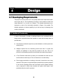
4.1 Developing Requirements ...................................................................24
4.1.1 Additional Functionality..............................................................24
4.2 Assessment of Options........................................................................25
4.2.1 Software Tools ...........................................................................25
Key Advantages of Visual Basic .NET .........................................26
4.2.2 Programming Philosophy ..........................................................26
4.3 System Fundamentals.........................................................................27
4.3.1 Multi Threaded Solution.............................................................27
2
4.3.2 Modes of Operation ...................................................................28
4.3.3 User Interface.............................................................................28
The Signalling Display...................................................................29
Menu Bar........................................................................................30
Signalling Data...............................................................................30
Summary........................................................................................30
4.4 Detailed Design....................................................................................31
4.4.1 Device Objects ...........................................................................31
4.4.2 Layout Data Class......................................................................33
4.4.3 Design Mode ..............................................................................34
User Interface.................................................................................34
4.4.4 Data Validation...........................................................................35
4.4.5 Test and Operate Modes...........................................................35
4.4.6 Hardware Class..........................................................................37
4.5 In Depth Extracts..................................................................................37
4.5.1 Points..........................................................................................38
4.5.2 Routes ........................................................................................40
Route Set .......................................................................................41
Route Cancel .................................................................................42
4.6 Summary ..............................................................................................43
Implementation .............................................................................................44
Testing ...........................................................................................................45
6.1 Strategy ................................................................................................45
6.1.1 Testing Plan................................................................................45
[A] Module Testing.........................................................................45
[B] Development Order..................................................................46
[C] User Interface Correspondence Testing.................................47
3
[D] Data Validation.........................................................................47
[E] Random Testing.......................................................................48
[F] Test Mode.................................................................................48
[G] Demonstration Track ...............................................................49
6.1.2 Limitations...................................................................................50
6.1.3 Summary ....................................................................................50
6.2 Functional Testing................................................................................51
6.2.1 Module Testing...........................................................................51
6.2.2 Development Order ...................................................................51
6.2.3 User Interface Correspondence Testing...................................52
6.2.4 Data Validation and Random Testing.......................................53
6.2.5 Test Mode...................................................................................53
6.2.6 Demonstration Track .................................................................54
6.3 Performance Tests...............................................................................54
6.3.1 Reaction and Response Times.................................................55
6.3.2 System Resources.....................................................................55
6.3.3 Hardware Requirements ...........................................................56
6.4 Summary ..............................................................................................56
Conclusions ..................................................................................................57
7.1 Achievements.......................................................................................57
7.2 Critical Review......................................................................................58
7.2.1 Missing Functionality..................................................................58
7.2.2 Data Format and Version Problems .........................................58
7.2.3 Graphics .....................................................................................59
7.2.4 Object Model and Retrieval .......................................................60
7.3 Future Enhancements .........................................................................61
References.....................................................................................................62
4
Websites .....................................................................................................62
Books ..........................................................................................................63
Other Documentation.................................................................................64
MERG Technical Bulletins..................................................................64
Railtrack Standards.............................................................................65
Appendix A....................................................................................................66
RPC System Overview ..............................................................................66
RPC PC – RPIC Interface Specification ...................................................71
Appendix B....................................................................................................82
Horton Layout.............................................................................................82
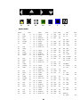
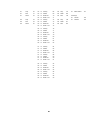
Appendix C....................................................................................................89
Symbol Set .................................................................................................89
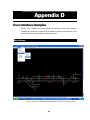
Appendix D....................................................................................................92
User Interface Samples .............................................................................92
Main Screen.........................................................................................92
Design Mode Forms............................................................................93
Test Mode............................................................................................97
Hardware Test Utility...........................................................................98
Operate Mode......................................................................................99
Appendix E ..................................................................................................100
Project Progress...................................................................................... 100
Project Plan....................................................................................... 100
Monthly Progress Reports ............................................................... 105
Appendix F ..................................................................................................113
Financial Statement ................................................................................ 113
5
VOLUME 2
Appendix G …………………………………………………………………….. 1
Source Code …………………………………………………………………1
A CD-ROM containing the Project Report, Source Code, Installation
Software and Supporting Documentation is attached to the rear cover of
Volume 2.
6
Introduction
Chapter
1
Model Railway Computer Control Centre
Realistic PC based Signalling for the Model Railway
Think of Model Railways, and you probably think of a Hornby train set or a carefully
modelled scene by elderly anoraks with finely crafted steam engines from the past.
Whilst these stereotypes remain true, there is more to model railways.
Some modellers prefer instead to recreate in miniature, the current railway scene. In
the UK, this has seen the increasing use of multiple unit operation, modern standard
locomotive designs and with privatisation, a huge array of colourful liveries. Few
notice the increasingly complicated signalling systems that allow the trains to operate
safely on crowded and complex track layouts.
A common feature of many so called, Modern Image layouts, is to incorporate a
working signalling system to add interest. Modern Signalling is colour light and
computer controlled. The left hand cover photo shows a real VDU based control
centre at Stoke On Trent. A basic tutorial in signalling is presented in Chapter 2.
In order to control realistic signalling for more complex track layouts, the switching and
interlocking required results in very complex hardware based solutions, often with
hundreds of electromechanical relays or a bewildering amount of logic gates. For this
reason, a number of railway modellers are turning to computer technology where
software can be used to save a mass of complex logic in hardware.
The Model Electronic Railway Group (MERG) are an international group of like
minded railway modellers who have developed a number of electronic solutions to
model railway problems and make them available as kits to members. A key product
family is the Remote Panel Control (RPC) system which provides Input and Output
capabilities to a PC via the serial or USB ports. The system is described in more detail
in Chapter 3.
7
During a work placement year, the author worked for a railway signalling company,
GE Transportation Systems. Amongst the product range is the Modular Control
System (MCS) which is a VDU based signalling indication and control system. The
MCS system linked to safety critical Solid State Interlockings (SSIs) which made the
vital interlocking checks.
This project sets out to develop software to provide modern signalling for the model
railway. As safety is not such an important consideration, implementation can be on a
standard PC and the User Interface, Interlocking and Hardware interface can be
integrated into a single piece of software.
1.1 About this Report
This report takes attempts to take a logical approach, taking the reader through every
aspect of this software project. This Introduction chapter establishes the background
to the project and sets out the key Aims and Objectives that the project is trying to
meet.
Chapter 2 provides a tutorial on the fundamental aspects of Railway Signalling in the
UK which is essential to understand the design decisions taken.
Chapter 3 has been provided to briefly explain the MERG RPC hardware system that
this software is being developed for. It also explains about the test bed for my project,
the Beckenham and West Wickham MRCs “Horton” layout. Photos and diagrams
assist in putting the theory and project into context.
Chapter 4 takes the reader into the Design of the Software. Starting with the
development of the project requirements and developing in detail the software design
and structure.
Details of the functionality of the final software and the testing strategies employed
can be found in Chapter 5 and 6 while Chapter 7 gives a critical evaluation of the
design decisions and project outcome, looking to future developments and looking
back with hindsight at elements of the design.
Full specifications of the RPC Hardware Interface, specific details on the
implementation on Horton, References for the project and the Visual Basic.NET
source code can be found in the Appendixes. The Source code and Installation files
8
together with this report are also provided on CD at the back of Volume 2 of this
report.
1.2 Aims and Objectives
The software should: [1] Provide Realistic Signalling on the Model Railway
The project is aiming for realistic modern signalling on the model railway. Further
details on relevant signalling can be found in Chapter 2.
However, there are some limitations and assumptions at this stage. It is assumed that
like on the real railway, a signaller will set the routes using the software, causing
signals to clear and points to change. And, a driver will drive the train, obeying the
signals. The trains are not controlled or driven by the software – although there may
be an interlock configured with the train power supply.
As a further limitation, and reflecting the operation of most model railways, there is no
timetable or sequence being operated and so there is no requirement for an
“Automatic Route Setting” system which would automatically set routes based on a
timetable. The signaller sets all routes manually.
It has to be assumed that the layout is suitably constructed and wired with suitably
chosen track sections (circuits), signal positions and wiring. For the software to be
effective, the layout needs to be signalled prototypically albeit with some
simplifications.
[2] Provide a User Interface similar to Real VDU Control Centre
A key objective is a desire to not just provide realistic signalling, i.e. correct signal
aspects and interlocking, but also for the User Interface to be similar to that found on
real VDU based control systems. This extends to many of the symbols and colours
used as well as the method of operation and mouse clicks. For the real railway, this is
set out in Railway Standards GK/RT/0025 and RT/E/S/17504. Railway Safety Ltd
does not permit their reproduction in this report.
9
The display has to update in real time based on what is happening on the railway.
Train movements can then be observed on the screen – there is no theoretical reason
why the signaller can not be remote from the layout.
In addition, a key operating concept, Entry – Exit (or NX) route setting is required to
speed and aid route setting. This is explained further in Chapter 2.
By providing a similar user interface, the operating experience for the layout operators
is enhanced and in addition, by projecting the computer screen onto a screen at
exhibitions, provides a dramatic and obvious demonstration to the public of how the
layout being is operated. This generates interest and educates on signalling
principles.
[3] Be Functional and Practical
This is not simply a university project – The author fully intends to use the software
developed to control a real model railway layout. In addition, it is intended to provide
the software free of charge and open source on the internet for others to use. So this
software must be fully functional and address the practical needs of model railway
layouts.
To this end, the software must be reliable and able to operate continuously for long
periods. A number of detailed design issues also need to be thought out to adapt
standard signalling practice to be useful and workable on a typical model railway. A
degree of flexibility is required to allow non standard extras to be controlled. Railway
modellers are ingenious and always finding new things to add. Examples might
include playing announcements, crossing warning lights or train sound effects.
[4] Be User Configurable
It should be stressed that the software is not just for a single model railway layout.
The software needs to be fully configurable for any reasonable exhibition sized layout.
This presents a number of challenges but makes the software a great deal more
flexible. The design of the layout is not a task that needs to be carried out frequently –
indeed once entered, it would only need changing if the physical track or signalling
was changed or if some aspects of the interlocking needed to be amended.
10
The infrequent change of the layout details mean that this section of the software can
be designed primarily for functionality and only secondly on usability grounds. It does
not matter if it takes some time to set out a complex layout.
A further issue that follows on is that the data created needs to be saved to disk and
opened again at a later date – data can not be recreated from scratch for each use of
the software.
[5] Be as simple as possible to configure
The interlocking data needs to be as user friendly as possible. Real systems and
some other model railway software relies on a script based approach. This puts off
many railway modellers who whilst understanding signalling, are not comfortable with
even the simplest elements of software.
[6] Develop within certain limitations
Finally, there are some limitations to the software which need to be set out at this
early stage. These have been set to match the author’s interest and personal
requirements but also to limit the project to some realistic boundaries!
These limitations are very simply that the software is designed for use only with the
MERG RPC Hardware System (running in RS232 mode only) and that the signalling
recreated is based on UK Colour Light signalling practice.
The software must be PC based and designed to work under MS Windows on a
modern PC. This is the most widely available platform. In addition, the RPC hardware
is designed to work with the RS232 serial port, easily available on most PCs.
1.3 Summary
The project has been introduced and 6 clearly defined objectives defined. These
Objectives are used extensively in the Chapter 4 to determine the direction of the
Design decisions.
Chapter 2 considers the Signalling concepts which the software is required to
implement and replicate.
11
Chapter
2
Background
Modern UK Signalling Practice
This section is designed to explain the UK Signalling principles which must be
understood in order to appreciate the design decisions taken. Whilst being based on
prototypical signalling, model railway signalling clearly does not have the serious
safety implications of the real railway. For this reason, even on well signalled model
railways, such as Horton, described in this chapter, the signalling does not come
close to that required of the real railway.
This tutorial on signalling will only focus on the aspects that are relevant to model
railways and to this project. Some areas have been simplified and there are some
areas where the Model Railway requires additional features to be practical in an
exhibition environment.
Any differences to signalling concepts for model railways have been identified but
large areas of Signalling Practice have been omitted for simplicity as they are not
relevant to the project.
For further reading, the author recommends: “BR Signalling Handbook” by Stanley Hall. ISBN 0-7110-2052-3 Ian Allan Publishing Ltd, 1992
Railway Technical Web Pages - http://www.trainweb.org/railwaytechnical/sigind.html
2.1 Why Have Signalling?
Signalling is a vital element of any railway. It ensures the safety of the train and
therefore the passengers. From the earliest railways, as soon as there was more than
one train on a network of railway tracks, there was the potential of trains colliding!
Unlike road vehicles, trains can not stop quickly. Even with modern braking systems,
a High Speed Train takes over a mile to stop from full speed – 125mph.
And so you have the two key reasons for signalling: 12
1) Keep trains apart from each other
2) Give trains sufficient warning of the need to stop
Neither of this is particularly relevant for model railways but the signals positioning
and indications are based on these key facts – even if they are only for show on the
model.
2.2 Early Signalling
Early signalling consisted of a “policeman” who stood by the side of the line and
indicated for a train to stop or proceed. After allowing one train to go, he would wait a
specified time before allowing a second train to proceed. After some time, a signal
was developed to replace hand signals and the semaphore signal was invented. This
was fine until the train in front broke down around the corner and the second just
ploughed in the back!
Block Sections
“Policemen” were soon replaced by railway signalmen and the newly invented signals
became mechanically controlled from signal boxes. Following some accidents and
with the development of the electric telegraph, systems were developed to allow
communication between adjacent signal boxes. The signalman at the far end of a
section could then tell the other signalman that the train had arrived safely and the line
must be clear to allow a second train.
The rules were very simple – signal boxes had to be positioned at suitable positions
along the line – usually at stations, and only one train was allowed in the “block
section” between signal boxes at any one time.
Soon the systems developed further, to electrically interlock the signals with the
electric telegraph between the signal boxes. And as train speeds rose, Distant Signals
were positioned ahead of the “Stop signals” to give advanced warning of the need to
slow down.
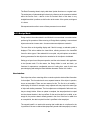
Junctions and Conflicts
We now come to junctions – that is where one line joins another using a switching
piece of track, called Points. Quite obviously, two into one doesn’t go. Signals protect
13
all junctions and conflicting movements. Before a signal can be cleared, the points
must be moved to the correct position for the movement. Points have two positions,
one for each direction, known as “Normal” and “Reverse”. Only one movement can
be signalled across a simple junction at a time.
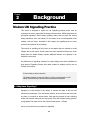
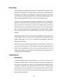
• Diagram 2.1 shows a simple junction layout. Signal 1 could not clear at the same time as Signal 2.
Points, A must be set correctly before the signal is cleared. Also, Points A must not move while there is a
train on the points.
This simple concept is known as interlocking and on both real and model railways is
vital to the safe and successful operation of the railway. It obviously extends to much
more complicated layouts to ensure that no two conflicting movements can
simultaneously have clear signals at the same time.
Track Circuits
As well as protecting points from moving under trains, signallers need to know or be
reminded where the trains are. Track Circuits were developed to detect where trains
are and provide train detection. This is achieved by splitting the track into sections.
These are then electrically isolated from each other by providing insulated joints in the
rails and electrically connecting all other rail joints.
A power supply is fed into one end across the two rails and a relay placed at the other
end. If a train is on the track, its wheels short circuit the relay and cause the relay to
de energise. The track circuit becomes Occupied. When the relay is energised, the
track circuit is Clear. The relay can then control lamps in the signal box or other
interlocking as required.
14
2.3 Modern Signalling
Centralised Control
To maximise efficiency and man power and to apply area wide regulation of lots of
trains through a network of lines, signal boxes got larger and more centralised. This
was achieved by the introduction of power signal boxes with electric, colour light
signals and motorised points and widespread introduction of track circuits.
• Photo 2.2 Large Power Signal Box at Exeter, © P.S.Bellamy
These centres consist of large illuminated track diagrams and push button control,
often with many signalmen in a single signal centre.
Track Circuit Block
In a large centre, Track Circuits are widely used. “Block Sections” as described
previously are replaced by one or more Track Circuits. Signals interlock with the Track
Circuits to ensure that the line is clear as far as the next signal. On the Signalman’s
diagram (or Panel), Occupied Track Circuits show as a row of red lights along the
track.
Away from station and junction areas, automatic signals are provided which require
no action from the signaller. They work automatically based on Track Circuits ahead
and the aspect (colour) of the following signal.
15
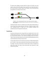
Signals
Modern Colour Light signals combine the standard semaphore signal with distant
signals to give drivers advanced warning of following signals. This permits higher line
speed and provides higher track capacity by allowing trains to follow each other more
closely, although at lower speeds. There are three types, Two Aspect, Three Aspect
and Four Aspect – Two and Three Aspect signals are used on quieter lines with fewer
trains and slower speeds.
Two Aspect Signals, simply show Red or Green. Distant, Yellow/Green signals are
often placed ahead of home signals.
Three Aspect Signals, show Red, Yellow or Green. Yellow indicated that the signal
ahead is at Red and therefore gives advanced warning for the driver to slow down.
Four Aspect Signals are most common on busy routes. A Double Yellow aspect is
included to give advanced warning of a single Yellow signal.
• Diagram 2.3 Sequence of Four Aspect Signal aspects behind a train, © Railway Technical Web Pages
The author appreciates that other types and variations of main signals exist for
various reasons.
16
Route Setting
In older signal boxes, signallers had to operate a mechanical lever or switch for each
individual point that had to be changed and then another for any signals required to
be changed. If the layout was complicated, a single train movement could require
numerous actions. With larger areas of control, route setting systems developed. This
has now been established as the Entry – Exit or NX Route Setting system.
The track layout and signal positions are shown in schematic form on a console. Each
Signal has a push button. Routes are defined as the path from one signal (The Entry
Signal) to the next (The Exit Signal). To set the route, signallers simply press the first
signal and then press the next signal the train will come to. The route setting system
will “call” all points in that route the required position and allow the Entry Signal to
show a proceed aspect, which it evaluates based on the track circuit occupation
beyond it.
If there were 3 signals in a row, S1, S2 and S3, the signaller would need to set Route
S1-S2 followed by S2 – S3. There is only a single button for each signal, so the
signaller would press S1, S2, S2, S3. A Route may be cancelled by “pulling” the
button at the Entry Signal.
Routes can be used to simplify the interlocking. If two routes conflict, it is obvious only
one can be set at the same time. Once requested, if the route is available, points are
called. If these are detected correctly set and all the track sections are clear, the
Route will set, enabling the Entry signal to clear. The Route Set is indicated by a row
of white lights on the track diagram.
In Depth features
Route Release
In modern signalling centres, after the passage of a train over a route, the route
automatically cancels itself. If a second train needed to travel, the signaller would
have to set the route again. This is known as Train Operated Route Release (TORR).
It should be realised that the Entry signal itself would return to danger (Red)
automatically as the train occupied track circuits beyond the Entry Signal. The route
needs to stay set until the train is clear of all track circuits within the route in order to
protect the route for that train.
17
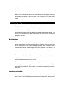
There is a limitation to this however. Consider the following example.
• Diagram 2.5 Route Release Example
Train x is signalled from Signal 1 to Signal 2 at the end of a station platform. The train
stops at the station. As the train has not cleared all the track circuits within the route,
the route stays set. Train y is now waiting at Signal 1 and wants to go to Signal 3. The
route is clear but the original route is still set. There must be a method for the initial
route to timeout once the train arrives at the platform so a second route can be set.
An equivalent system is needed for the model railway for the same reason.
Call On / Shunt signals
For shunting movements at slow speed, often in sidings, a special type of signal is
used which shows Stop or Proceed. Call On signals are similar in appearance but are
used to allow trains to enter already part occupied platforms. A separate Exit button is
used to select this rather than a normal signal aspect. When these signals are
mounted on the same post as a main signal, the shunt signal doesn’t have a stop
aspect, as there is already a Red, stop aspect on the main signal. This is reflected in
the signallers display.
Isolated Exits
For Call On signals and at the end of a line – a terminus or dead end siding, there is
no Exit Signal, but a button is still required to act as the exit signal for the route setting.
These are known as Isolated Exits.
Auto Buttons
When referring to Routes, it was stated that if a second train comes, the signaller has
to set each route again. This is fine if trains go different ways at a diverging junction
but if many of them go the same way, it is rather inefficient. For this reason, Controlled
Signals are often provided with an Auto Button or A Button. After setting a route, a
18
separate Auto Button may be set. This allows the signal to clear again on its own
once the first train is clear of the route. When a different route is required, the Auto
Button can be cancelled and another route set. (Real installations are slightly more
complicated than this)
Auto signals – ER Buttons
All signals so far described have been Controlled – The signaller sets them for each
movement. Away from junctions, there may be many miles of Automatic signals.
These always try to show the best possible aspect to the driver and are only affected
by the occupation of track circuits beyond them. For emergencies, they may be
provided with Emergency Replacement (ER) buttons to force them to Red.
Point Keys
For maintenance, safety protection, or if the points are failing to operate properly, it
can be useful to manually operate individual points. Switches, known as Point Keys
are provided for this purpose. These have three states – Normal, Centre and
Reverse. When Centred, the points are free for the Route Setting system to call as
required. When Normal or Reverse, the points are moved and locked in that position
although if set correctly, a route may be set through them.
Point Pairs
Two points may operate as a pair. A common configuration is a crossover, allowing
trains to move from one line, to an adjacent one. One control operates both ends of a
crossover – two sets of points.
2.4 Computer Based Signalling
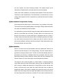
VDU based signalling control
Large Signal Centres are now moving from illuminated panels with push buttons to
computer based control on VDUs. The track layout and all indications are shown on
screens to the signaller. Control switches are replaced with clicks on screen elements
with a tracker ball. The left hand cover photo shows a typical arrangement.
Often Automatic Route Setting can be provided using timetable data. As defined in
Objective 1, this is not to be developed for Model Railways.
19
Electronic interlocking
Electromechanical relays to perform interlocking and route setting functions are
replaced with Vital Computer Processors, data links and interlocking data.
Symbols
A series of symbols have been developed to depict the schematic of the railway and
signalling states on the screen. Model Railway Computer Control Centre (MRCC)
needs to look similar to meet Objective 2.
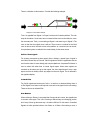
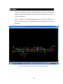
• Figure 2.4 Typical Screen Layout, © SimSig (Simulation Screenshot). This shows many features not
described or required for model railways.
Mouse Actions
There are pre-defined mouse actions to control the railway which need to be similar to
meet Objective 2.
Signaller Action
L / R Click
Click on?
L (Normal)
R (Reverse)
Point Tips
Route Setting
Left
Entry Signal, then
Exit Signal
Cancel Route
Right
Entry Signal
Left
Control symbol
Right
Control symbol
Key Points
Set Misc Control or A Button
Cancel Misc Control or A Button
20
2.5 Model Railway Features
On the model railway, some things have to be different to the real railway for practical
reasons. Safety is not as important! One example is for Points – in reality, these
would be locked if there was a train on them, on a model, unreliable track circuits may
lock them unnecessarily. Running trains is more important than safety on a model! In
any case, model track circuiting is far more complex – See Chapter 3 for how the
RPC system achieves this.
Junction Indicators
Junction Indicators are rows of white lights on top of signals to indicate to the driver
that a diverging route is to be taken. They only display when the signal is showing a
proceed aspect and the route is set for the diverging route. On the Model Railway, a
separate output bit controls the Junction Indicators and this needs to be defined with a
Signal and a Route to control the output.
ATP Relays
To prevent embarrassing collisions on Model Railways, sections of track ahead
signals protecting junctions can be electrically isolated, bringing the electric train to an
immediate halt. This is achieved through an Automatic Train Protection (ATP) relay in
the power supply to that section. The relay can be connected to an output bit and the
software needs to ensure the output is set when the signal is not at danger or if a
move in the reverse direction is signalled.
Miscellaneous
There will always be miscellaneous functions which may be useful. Extra Controls
and interlocks for various reasons or gimmicks such as sound effects, working level
crossings or warning lights might be some of the extras that add interest to the model.
A flexible system for configuring additional inputs and outputs would be a real benefit.
2.6 Summary
This chapter has set out the signalling that is required to be implemented. Chapter 4
develops these into the Project Requirements. The next chapter provides information
on the Hardware system that provides the interface to the model railway.
21
Chapter
3
Hardware System
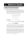
3.1 Remote Panel Control System
Developed by the Model Electronic Railway Group
The scope of this project relates only to the software development. However, the
software is ultimately being designed to integrate with a hardware system. Initially, this
is limited by Objective 6 to the MERG Remote Panel Control (RPC) system and only
in RS232 mode. However, the design should be such that it would be straightforward
to change to a similar hardware system or alternative RPC interface.
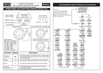
• Diagram 3.1 MERG RPC System Stack Diagram © MERG
The RPC system (when running RS232 mode) is based around an RS232 serial
connection to the PC. At the head of an RPC “stack” of modules is an RPIC Interface
module based around a PIC microprocessor. This handles the serial communications
with the PC and sends and receives data from plug in modules making up the stack.
Input and Output Modules are available and plugged in as required to suit user
requirements. Key modules are the SRI4 and SRO4 32 bit Input and Output modules
respectively. Other modules include Relay Output boards and importantly, the FTC
Track Circuit board. This detects trains in sections for model railways based around a
current sensor which is required as model railways use the running rails to power the
trains and conventional relay track circuits can not be used.
22
The software needs to know the configuration to determine the range of Input or
Output bits available to assign to devices on the screen synchronise with the
hardware. Input and Output ranges are separate, i.e. there is an input bit 0 and an
output bit 0 and these are independent.
MERG Technical Bulletins in the G16 series define the logic for this modules and
standard aspect codes for multiplexed operation of signals.
There is a comprehensive serial protocol defined for PC – RPIC communication and
this provides for individual bit, byte or whole system changes within a single message.
MERG Technical Bulletin G16/4 defines this protocol and this is presented in
Appendix A.
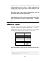
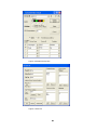
3.2 Horton Layout
The test bed for the software is the Horton Layout which the author has largely
designed and constructed. Some statistics are presented here as a measure of a
typical large layout’s requirements. This will provide a reference point when analysing
performance of the software and assists in the design of the user interface.
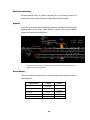
Size
8m x 3m (28’ x 10’)
Simultaneous train movements
6
Points
23
Signals
24
Routes
43
Track Circuits
39
RPC Modules
SRO4 x 3
DPR x 2
FTC x 5
SRI4 x 1
• Figure 3.2 Statistics for Horton (excluding old section of layout)
Further Details including RPC Bit allocation and a track diagram are to be found in
Appendix B.
Beckenham and West Wickham MRC: http://www.bwwmrc.org.uk
MERG: http://www.merg.org.uk
23
Design
Chapter
4
4.1 Developing Requirements
This project is unusual in that there is a very clearly defined set of requirements which
were known early on. The requirements are simply to work towards a solution that
meets Objectives 1 to 6 as set out in Chapter 1. The detailed requirements are to
implement as much of the functionality described in Chapter 2 as possible. The
detailed explanation of relevant signalling is by far the best way of presenting what
needs to be achieved.
4.1.1 Additional Functionality
In terms of functionality, a number of additional features were considered and the
design seeks to implement these where possible or ensure that the design does not
preclude them.
Point Detection would allow input bits to provide feedback on whether points have
actually moved.
Intelligent response from the Interlocking would ensure that if a request was
rejected, an explanation of why would be provided to the user. This is not
provided on real signalling systems but would assist less experienced operators.
A Train Describer would allow an identity to be associated with each train and
track that train around the layout. This is of limited use on a model railway.
Event Logging would allow a recording to be made of events that occur during
operation of the system. A logical development would firstly be passive playback
to view how the operating session went, and finally to active playback whereby
once a sequence of actions was recorded, the system could repeat it and
potentially relieve the need for operators.
24
4.2 Assessment of Options
Objective 6 presented within Chapter 1 sets out some limitations in order to be
practical. The key decisions are that the system must be PC based under MS
Windows utilising the RS232 interface to the RPC hardware system.
Objective 4 sets out the need for the system to be user configurable for different
layouts. Objective 2 requires some careful attention with the User Interface design.
4.2.1 Software Tools
An early decision was made to use a modern development environment. This was
primarily to familiarise the author with current software tools which is good experience
but also to allow the simple development of a professional looking application. Several
existing applications to work with the RPC system are outdated – some are even
DOS based. I wished to have a 32 bit windows application. Well known and therefore
well supported development tools were chosen – The author was inexperienced and
needed the support of websites, forums, books and other documentation. This
pointed towards Microsoft products.
A shortlist was drawn up of: MS Visual J
MS Visual C
MS Visual Basic
Visual J, being based on Java was ideal for an object orientated approach. However,
its support for Serial Port communication was limited. The software was to run on a
stand alone PC where as Java pointed more towards a Server – Client environment.
The clear choice was between Visual C and Visual Basic. Again, the author’s
inexperience played a significant role. Having worked with VBA behind MS access,
the author was more comfortable with VB. The project was considered to be
sufficiently complex without the steep learning curve of some elements of Visual C.
The memory management of Visual Basic was considered to be useful to a beginner
25
as VB’s “garbage collector” deals with freeing up RAM, helping to eliminate “memory
leaks” which common in C programmes if not carefully understood.
Further research revealed that the current version of Visual Basic, Visual Basic .NET
provided VB with almost the same functionality as C. The .NET framework provides
for reuse of many key structures which are common across all .NET applications.
.NET will be integrated into the next version of Windows, and until then, applications
will only run on PCs with the .NET framework installed. The .NET framework is
available free of charge from Microsoft and is redistributable.
Key Advantages of Visual Basic .NET
Easy to Program and learn the language. Wide range of support books, websites,
forums and documentation.
Full support for Object Orientation including Inheritance, polymorphism and
interfaces.
Built in, efficient data storage types such as ArrayList and SortedList.
Automated Memory Management and freeing up of dynamically allocated
memory when no longer required.
Good, simple graphical functionality which is essential for the GUI with specialist
symbols.
Built in serialization functions to serialize objects to file
4.2.2 Programming Philosophy
The choice between traditional procedural programming and Object Orientated
design was an easy one to make. Railway signalling consists of a limited set of
devices, many similar to each other. Object Orientation was an obvious solution. Each
device becomes an object and the objects interact with each other.
The approach is more flexible and allows for iteration of the design as understanding
of the problem and programming techniques developed. The system instantly
becomes more expandable, more flexible and simpler to understand.
26
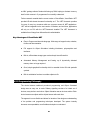
4.3 System Fundamentals
It was quickly decided that there needed to be a central storage of all User Configured
data. A database was considered but rejected as being unnecessary and over
complicated and so a LayoutData class was developed to store the required data.
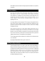
4.3.1 Multi Threaded Solution
After considering the Operate Mode requirements, a multi - threaded approach was
decided to be the most straightforward to allow devices such as signals and track
circuits to continuously update at the same time as the user was interacting with the
user interface. At the same time, the hardware should be constantly synchronising
with the software. So, there are three Operate and Test Mode threads: GUI,
DataProcessing and Hardware, all communicating through the objects that make up
the layout, which are stored within the LayoutData class.
• Diagram 4.1 Multi-Threaded Approach and Central Data Storage
Design Mode requires only the User Interface thread and the Layout Data. This
design also accommodates the testing strategy very well. The Hardware thread can
be coded and tested by the Hardware Test Utility and then integrated with the rest of
the system to form Operate Mode which utilises all three threads.
27
4.3.2 Modes of Operation
There need to be at least two modes of operation. A Design Mode where users define
the layout and interlocking and an Operate Mode where the system runs as a VDU
based signalling control centre as described in Chapter 2. This concept is already
adopted by at least three existing software packages for control of the RPC system
and is the most logical method.
However, with the complexity of interlocking data, coupled with the fact that many
layouts are large and often kept in storage when not exhibited, there is a need for an
off line test of the interlocking configuration. If the user, having set up and configured
the layout, had the ability to simulate inputs from the layout, any errors where data
was valid but not what was intended could be rectified.
This would also be useful for training and more importantly, would be the only
practical way to test the software functionality without the need for a large layout.
Chapter 6, Testing explains the testing methodology in detail.
Therefore, there will be three modes – Design, Test and Operate. Only Operate mode
will connect to the hardware.
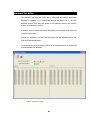
A need has also been identified to test the layout wiring and electronics. The
Hardware Test Utility should consist of a simple display of all input and output bits and
the ability to set and clear individual bits. This will also form a key part of the Testing
strategy.
4.3.3 User Interface
The User Interface has been considered as being fundamental to the system
because the Operating mode relies on specific symbols to both display the status of
the layout and allow the user to request operations on the layout. The whole screen,
with the sole exception of the menu is therefore available for the Signalling Display.
The obvious solution for the Design Mode is to view the same graphical image as
required when in Operating Mode. The layout can then be built up and amended as
required using a what-you-see-is-what-you-get interface. The alternative approach
28
would be to have some kind of text data format to be interpreted into a graphical
display. This would make designing layouts difficult and not user friendly.
The Signalling Display
A decision was taken to split the Signalling Display into a grid of lots of small tiles.
This is easier to manage than elements of differing sizes and it also gives way to
creating a symbol set of bitmap images. The alternative approach of drawing the
symbols would probably have led to a performance increase as less processing is
required, however it was decided that the most straightforward approach should be
taken, and this was to draw a set of bitmap images.
An example was found in a textbook of the User Interface for a Chess Game1. This
was heavily modified to provide a grid of 80 x 64 tiles. This was evaluated based on
the complexity of a typical large layout to fit on a screen with a sensible tile size of 16
x 16 pixels, being the smallest size to be able to draw a signal symbol and have user
controls at a useable size.
The whole display would therefore fill a large screen running at 1200 x 1600
resolution. Scrollbars are provided for lower resolutions.
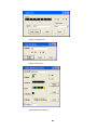
A symbol set was designed of 16 x 16 pixel symbols, each with a code and any tile
could have its symbol changed to any of the symbols. Appendix C shows the symbol
set and the codes used. Clicking on a tile would result in parameters identifying which
tile had been clicked. One object only may be assigned to each tile, giving each object
an x, y, and symbol code.
This is very important as this gives way to a central index of each tile in the grid,
referencing the relevant objects from the store of object. There would have been
significant problems linking to the correct objects if a system other than a grid was
chosen.
In addition to objects that are related to a display tile, Routes, and the RPC Module
Configuration are not directly related to the screen.
1
Visual Basic .NET for Experienced Programmers, Prentice Hall : Fig 13.26
29
Menu Bar
It was decided that a Menu bar would be provided to give control to the users when
designing and configuring layouts and to allow changes of mode, and exiting the
software. This allows easy disabling of commands by setting the Enabled property.
Other options would have resulted in less space being available for the signalling
display and this is unacceptable as the whole display is used as an overview of the
layout to the operator. Floating windows for example, would obstruct the display.
Signalling Data
The direction for interlocking data to take is also fundamental to the way the system
operates. The interlocking data which is linking all the types of device together as
required could be based on user typed scripts, executed when called, as used by the
Solid State Interlocker application. It was considered that whilst greater flexibility is
gained by having, for example, signal aspects, based on an IF / THEN / ELSE
structure, it would not be user friendly. Railway modellers are not necessarily
computer programmers, and would rather deal only with signalling terminology.
For this reason, the objects have been designed to work with the minimum of
information and required data is only of a signalling nature and inputted via standard
windows controls, and not by any form of scripting.
Scripting would again benefit performance as scripts would only be run as required
but it was decided to avoid it for simplicity, both in programming and for users setting
up layout data.
Summary
The User Interface, featuring the signalling display, is at the heart of the system from
the users point of view. The grid concept underpins the way the system references
the Device objects and this is explained further in section 4.4.2.
The Symbol Set can be found in Appendix C and examples and explanation of the
elements of the User Interface are shown in Appendix D.
30
4.4 Detailed Design
4.4.1 Device Objects
The objects were modelled in UML. After some iteration the following Class diagram
was decided. As will be analysed in the Conclusion, with the benefit of experience, it
would not be done in the same way if repeated. It is appreciated that it may have
helped to break down objects further but it was considered that the additional code
required would probably exceed that used to repeat some blocks of similar code in
multiple objects.
Diagram 4.3 on the following page shows the UML Class Diagram of Device Objects,
showing the Generalisation that has been designed. Key Associations are also shown
for the Point and Track associations. In addition to these objects, there is a Route
Class. The Route Class is shown in Diagram 4.2 below. The Device Objects and
Routes are stored within the Layout Data Class and their operation described further
in subsequent sections.
Route
+ ID : String
+ EntrySig : String
+ ExitSig : String
+ Conflicting : ArrayList
+ NPoints : ArrayList
+ RPoints : ArrayList
+ TkSections : ArrayList
+ MiscTrue : String
+ MiscFalse : String
+ EarlyReleaseTrack : String
+ EarlyClrOcc : String
+ AButtonRef : String
+ USet : Boolean
+ AButtonSet : Boolean
+ TracksClear : Boolean
+ UpdateDetails (ID, SigEntry, SigExit, Conflicting, NPoints, RPoints,
Tracks, MiscTrue, MiscFalse, EarlyRelease, EarlyClrOcc, AButtonRef)
+ ValidateID () : Boolean
+ ValidateNX() : Boolean
+ ILDataValid() : Boolean
+ ValidateILData() : String
+ CallRoute()
+ CancelRoute()
+ Update()
• Diagram 4.2 UML Class Diagram for Route Class
31
ScreenElement
{abstract}
+ X_Pos :Integer
+ Y_Pos :Integer
+ ChangePosition(x , y)
Signal
{Abstract}
StaticMisc
+ DeviceID : String
+ CurrentState : Boolean
+ Symbol : Integer
+ MiscType : String
+ TypeCode : Integer
+ RPCRef : Integer
+ UpdateSigDetails (SigID, DefAspect, Symbol, Routes,
ILMiscTrue, ILMiscFalse)
+ ChangeSymbol (Symbol)
+ ValidateSig() : Boolean
+ ILDataValid() : Boolean
+ ValidateILData() : String
+ UpdateDetails (DeviceID, TypeCode, RPCRef)
+ ChangeSymbol (Symbol)
+ Validate() : Boolean
+GetNextSigAspect() : Integer
+ Update()
+ SetMisc()
+ CancelMisc()
+ EnterDesignMode()
+ EnterTestMode()
+ EnterOperateMode()
TrackElement
{Abstract}
TrackSection
MiscOutput
+ SignalID :String
+ SigDefAspect :Integer
+ SigAspect : Integer
+ Symbol : Integer
+ MiscTrue : String
+ MiscFalse : String
- RoutesFromSig : ArrayList
+ TkName :String
+ Symbol :Integer
+ TC : Boolean
+ TOcc : Boolean
+ USet : Boolean
+ TORRAv : Boolean
+ APressed : Boolean
+ TCInputBit : Integer
+ AttachedTrackElements : Boolean
- TrackElements : ArrayList
+ DeviceID : String
+ CurrentState : Boolean
+ Symbol : Integer
+ MiscType : String
+ TypeCode : Integer
+ RPCRef : Integer
+ ILAndTF : Boolean
+ ILActiveChk1 : Boolean , ILDeviceType1 : Integer, ILDeviceID1 : String, ILCondition1 : String
+ ILActiveChk2 : Boolean , ILDeviceType2 : Integer, ILDeviceID2 : String, ILCondition2 : String
+ ILActiveChk3 : Boolean , ILDeviceType3 : Integer, ILDeviceID3 : String, ILCondition3 : String
+ ILActiveChk4 : Boolean , ILDeviceType4 : Integer, ILDeviceID4 : String, ILCondition4 : String
+ ILActiveChk5 : Boolean , ILDeviceType5 : Integer, ILDeviceID5 : String, ILCondition5 : String
+ UpdateDetails (DeviceID, TypeCode, RPCRef, ILAndTF, ILActive1, ILType1, ILID1, ILCond1,ILActive2, ILType2, ILID2,
ILCond2, ILActive3, ILType3, ILID3, ILCond3, ILActive4, ILType4, ILID4, ILCond4, ILActive5, ILType5, ILID5, ILCond5)
+ ChangeSymbol (Symbol)
+ Validate() : Boolean
- CheckConditionValid(DevType, DevID, Condition) : Boolean
+ ValidateILData() : String
- CheckLineValid(CheckTF, DevType, DevID) : String
- GetDevTypeStr (DevType) : String
+ UpdateAspect()
+ EnterDesignMode()
+ EnterOperateMode()
SignalShunt
Signal2Aspect
+ Multiplexed : Boolean
+ MainSigAssn :String
+ RPC1 : Integer
+ RPC2 : Integer
+ Multiplexed : Boolean
+ RPC1 : Integer
+ RPC2 : Integer
+ Update()
+ EnterDesignMode()
+ EnterTestMode()
+ EnterOperateMode()
PlainTrack
+ PointAssn : Boolean
+ PointsRef : String
+ PointsPosRef : String
+ PointsRef2 : String
+ PointsPosRef2 : String
+ UpdatePointAssn (AssnTF, Ref1, Ref1NR, Ref2, Ref2NR)
+ Validate() : Boolean
+ UpdateSymbol(Symbol)
+ UpdateDetails (SigID, DefAspect, Symbol, MultiTF, RPCRef1,
RPCRef2, MainAssnTF, Routes, ILMiscTrue, ILMiscFalse)
+ Validate() : Boolean
+ UpdateAspect()
+ EnterDesignMode()
+ EnterOperateMode()
+ UpdateDetails (SigID, DefAspect, Symbol, MultiTF,
RPCRef1, RPCRef2, Routes, ILMiscTrue, ILMiscFalse)
+ Validate() : Boolean
+ UpdateAspect()
+ EnterDesignMode()
+ EnterOperateMode()
Signal3Aspect
Signal4Aspect
+ Multiplexed : Boolean
+ MainSigAssn :String
+ RPC1 : Integer
+ RPC2 : Integer
+ RPC3 : Integer
+ Multiplexed : Boolean
+ MainSigAssn :String
+ RPC1 : Integer
+ RPC2 : Integer
+ RPC3 : Integer
+ RPC4 : Integer
+ UpdateDetails (SigID, DefAspect, Symbol, MultiTF, RPCRef1,
RPCRef2, RPCRef3, MainAssnTF, Routes, ILMiscTrue, ILMiscFalse)
+ Validate() : Boolean
+ UpdateDetails (SigID, DefAspect, Symbol, MultiTF, RPCRef1, RPCRef2,
RPCRef3, RPCRef4, MainAssnTF, Routes, ILMiscTrue, ILMiscFalse)
+ Validate() : Boolean
+ UpdateAspect()
+ EnterDesignMode()
+ EnterOperateMode()
+ UpdateAspect()
+ EnterDesignMode()
+ EnterOperateMode()
• Diagram 4.3 UML Class Diagram of Device Objects
32
+ UpdateDetails (PointID)
+ Validate() : Boolean
+ UpdateTkAssn (AssociatedTF, TkSecAssn)
+ ValidateTk() : Boolean
+ ChangeSymbol (Symbol)
+ SubRouteSet()
+ SubRouteClr()
+ OccupyTrack()
+ ClearTrack()
IsolatedExit
+ AssociatedPointID : String
+ SymbolCode : Integer
+ UpdateKey(NCR)
+ Update()
+ EnterDesignMode()
+ UpdateDetails (TkSecID, TC, RPCBit)
+ Validate () : Boolean
+ AddTrackElement (x,y)
+ RemoveTrackElement (x,y)
+ Update()
- EvaluateCondition(DevType, DevID, LineCond) : Boolean
+ EnterDesignMode()
+ EnterTestMode()
+ EnterOperateMode()
+ UpdateDetails (SigID,
DefAspect, Symbol,
Routes, ILMiscTrue,
ILMiscFalse)
+ Validate() : Boolean
PointKey
+ DeviceID : String
+ Symbol : Integer
+ IsTkAssn : Boolean
+ TkSecAssn : String
Points
+ PointName : String
+ MiscTrue : String
+ MiscFalse : String
+ OutputBit : Integer
+ NRInvert : Boolean
+ PointPair : String
+ Position : String
+ Key : String
+ PointAssn : Boolean
+ PointsRef : String
+ PointsPosRef : String
+ AttachedTrackElements : Boolean
- PointAssns : ArrayList
+ UpdatePointAssn (AssnTF, Ref, NR, PointPair)
+ UpdatePoint (PointName, RPCBit, NRSwap, MiscTrue, MiscFalse)
+ Validate() : Boolean
+ UpdateSymbol(Symbol)
+ AddTrackElement (x, y)
+ RemoveTrackElement (x, y)
+ ILDataValid() : Boolean
+ ValidateILData() : String
+ SubRouteSet()
+ SubRouteClr()
+ OccupyTrack()
+ ClearTrack()
+ MoveNormal()
+ MoveReverse()
+ KeyNormal()
+ KeyReverse()
+ KeyCentre()
+ CallNormal (Sender)
+ CallReverse (Sender)
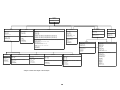
4.4.2 Layout Data Class
A central data depository was planned to allow a single location to retrieve objects
from. It was also logical to have data stored within a single class in order to use the
.NET serialization functions to Save to disk and reconstruct from Disk.
The .NET framework provides a simple, dynamic, efficient object storage mechanism,
known as an ArrayList. It is said to be a cross between an Array and a Linked List. An
ArrayList is provided for each type of object. For the main Device Objects, a further
ArrayList, Devices contains the ArrayList’s holding the objects. Routes objects are
stored in similar SortedList structure to aid efficient retrieval by RouteID.
The Layout Data Class also manages the data retrieval by other objects and to do
that, a number of indexes are maintained.
A key Index is the DeviceIndex which is an 80 x 64 x 2 array. Layer 1 maintains a
value for Object Type which is a numeric value referring to the location of the Object
Collection within the Devices ArrayList, or -1, indicating that position on the grid is
empty, and hence available for objects to be created. Layer 2 of the Array maintains
the position within each Object Collection of the specific Object Instance. This Index is
essentially the link between the grid position on the user interface, which is used as
the main reference point for Device Objects, and the actual location of the object in
memory.
Devices which require them and Routes must have unique names to act as
references and so indexes are maintained to record names currently in use.
A register of Hardware Bits allocated is kept to ensure that the number of bytes
available can not be reduced (by changing the Module Configuration) while objects
exist referencing a bit that would no longer be available. The maximum number of
bytes available in the current hardware configuration is also stored.
A very large number of functions are provided to aid retrieval of data and updating of
indexes from the class. Interfaces are also set up through functions provided in this
class and the Operate Mode DataUpdate() functions are all in this class to call
Update() functions of each object instance requiring continuous update.
33
The Data Processing thread, simply calls these Update functions on a regular basis.
The easiest way of understanding this class is by reference to the comments included
within the Source Code – data.vb is the file involved. Much of this class is very
straightforward but it performs a vital function at the centre of the system, as diagram
4.1 shows.
Subsequent sections refer to some of these processes in more detail.
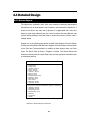
4.4.3 Design Mode
Design mode is the mode started in and finished in to ensure data is consistent when
performing file operations. When returning to Design Mode, updating is removed and
objects returned to a known state – the same state new objects are created in.
The user clicks on the signalling display and if the tile is empty, a selected symbol is
displayed. This action enables the Insert Menu, allowing access to the Insert/Edit
forms for device types. If the selected tile is occupied, only edit options are enabled,
allowing parameters for that object to be amended or for the object to be deleted.
Setting up a layout is an infrequent operation, and the main interest in this application
is the Operate mode. For this reason, the Design Mode is crude and basic, yet
functional. It represents a considerable amount of coding time, most of which was
spent designing and testing the Data Validation elements. Section 4.4.4 refers.
User Interface
Each object has a form containing all the controls required to obtain all the information
for that object. The form also has its own, separate instance of the object in question,
known as tempobject. There are two reasons for this. The first is to aid usability –
whilst laying out a track for example, many adjacent cells may require the same type
of object with similar parameters. The form objects are not disposed of after each use,
they are simply hidden. When an update is complete, the tempobject data is copied
into the relevant location in the LayoutData. So the next time the form is called, on an
empty tile, the previous data is already present in the form. If the form is called from
an occupied tile, the data is copied from the LayoutData to the tempobject.
The second benefit is to assist with ensuring that invalid data is not allowed in the
LayoutData. If the new or altered data (temporarily stored within tempobject) is invalid,
34
data validation prevents the data from being accepted and the data is not copied into
LayoutData.
4.4.4 Data Validation
One of the most essential elements of the system is data validation. The purpose of
Data Validation is very clear - to ensure the data is valid, complete and accurately
cross referenced. It is designed to be robust enough to prevent illegal data to be
accepted that would cause the system to crash or cause data corruption. It is not
however designed to ensure the data is necessarily sensible or correct from a
signalling point of view.
A two stage validation has been developed. The first stage must be passed before an
object can be created or updated. The second is checked and a detailed error report
generated if required but the data is accepted. In all cases, a relevant error message
is displayed to the user.
All the second level checks are run again before changing modes and the user is
prevented from changing modes if the checks fail. The reason for this two stage
approach is to give more flexibility in entering data. If rules were rigidly enforced all the
time, the user would have to create objects in precisely the right order to pass all the
validation checks first time. This would become very frustrating.
The two stage approach allows a reference to be made but for the referenced device
to be created later.
An example of Data Validation Code is given in section 4.5.1.
4.4.5 Test and Operate Modes
Test and Operate modes are very similar to each other but work quite differently to
Design mode. Before changing from Design Mode, the second level of data validation
is checked and if successful, all devices are set up for the new mode. The Signal and
Miscellaneous Devices interfaces are set up and Signals are set to their default
aspect (as specified by the user). Symbols are changed to their default state and in
Operate Mode, some symbols are hidden as they are not required (Track Sections
and Hidden Miscellaneous Devices).
35
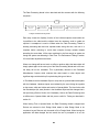
The Data Processing thread is then launched and this executes with the following
sequence: Wait
100ms
Update() called for
each Route
Update() called for
each Track Section
Update() called for each Signal
(using the ISignal Interface)
Update() called for each Misc Device
(using the IMisc Interface)
• Diagram 4.4 Data Processing Thread
Each step, causes the Update() function of the individual objects stored within the
LayoutData to be called and the objects have the necessary code to update as
required. A semaphore is used to indicate when the Data Processing Thread is
actually processing data and user requests made during this time, wait until it is
complete before executing to avoid data corruption through multiple threads
amending the same data. 100ms was considered to be fast enough to appear as
though the system was behaving in Real Time. The Performance Testing in section
6.3 looks further at performance issues.
Where one change will have a knock on effect on another object, the latter object will
simply update again at the next cycle of the Data Processing thread and to the user
the delay will not be noticeable. This is particularly relevant to the Calculated
Miscellaneous Outputs which evaluate their state based on other objects and
significant logic could be built up if required using this type of device.
In Test Mode, there the Hardware Object is set up but no synchronisation takes place
with the Hardware. Hardware Inputs are simulated by the user clicking the symbols
on the screen, which are hidden and inactive in Operate Mode. The User Action calls
the SimulateInput (bit, state) function in the Hardware Object and this changes bits in
the Input Array (Refer to Section 4.4.6 Hardware). Hence, the Data Processing sees
no difference to Operate Mode and this proves useful for Testing as described in
section 6.1.
When leaving Test or Operate Mode, the Data Processing thread is stopped and
Devices are returned to their Design Mode states to allow Design Mode to be
consistent. Layout Data can only be saved to file in Design Mode. When leaving the
application with data changed and not saved, the user is prompted to do so, the
36
software switching itself back to Design Mode if required. File Open can only take
place in Design Mode.
4.4.6 Hardware Class
The Hardware Class is responsible for all hardware aspects of the software.
Essentially it maintains two arrays of Boolean values that are dimensioned according
to the number of Modules connected. One form is provided to obtain this information
and the maximum number of bytes is stored with the Layout Data. ReadBit(bit) allows
the Input Array to be read back and objects poll this as part of their update routines.
SetBit(bit) and ClearBit(bit) set bits in the Output Array.
The Hardware Object contains a synchronize function which uses RPC Type 0
messages to send and receive all bytes from the hardware to and from the arrays.
RPC Type 3, 4 and 5 messages are also coded and these are used by the integral
Hardware Test utility which provides a simple user interface to deal direct with the
Hardware. The RPC Message formats are defined in Appendix A.
Connect and Disconnect functions prompt the user for which Port to use. The code
for the Com Port Select form and the separate RS232 Class which provides serial
communications are taken directly from an RS232 Tester application2 found on the
web and were reused. Once connected, a new thread is launched to perform the
synchronisation at the same rate as the Data Processing thread.
4.5 In Depth Extracts
This section looks in detail at the design of two elements of the project; Points and
Routes.
The Points example focuses on the Design Mode with samples of Data Validation
and Object Creation and modification.
The Routes example shows how this critical element of the interlocking works in Test
and Operate Modes. This shows the complex nature of the logic for interlocking and
animation of the correct symbols on the screen.
2
http://www.freevbcode.com/ShowCode.Asp?ID=4666
37
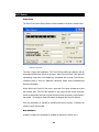
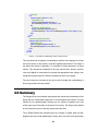
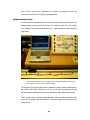
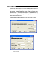
4.5.1 Points
Points Form
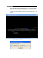
The Point Form used in Design Mode to obtain the data for the point is shown below.
• Figure 4.5 Points Form
The form is largely self explanatory. The Track Section makes the reference with an
electrically isolated track section on the layout. Many Point and Plain Track elements
representing single tiles of the display are associated with a single Track Section.
Interlocking data is used for additional interlocking based around Miscellaneous
Devices to be added.
Works With is the Point ID of the point it works with if the point operates as a pairs
with another point. The RPC Bit reference is the output bit that moves the points.
Points are assumed to have the “Normal” direction as the horizontal or vertical track in
the symbol – Checking the Swap N/R makes the diagonal the “Normal” direction.
Point Leg Association is required for animating the screen correctly. If checked, the
reference given must be valid.
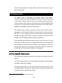
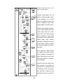
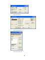
Data Validation
As data is changed, the tempobject is updated as described in Section 4.4.4.
38
Points Form
Point Object
Layout Data
Result = True
Call Validate()
•
[No ID]
Lookup XY using
Name Index
[ID Exists]
Object 1st Stage Data Validation
Return Device
Type using
Device Index
Call Data.Check
Reference(ID)
Result = False
● Diagram 4.6 UML Activity Diagram of Points
Show Error
Message
[<> -1]
[-1]
ID In Use
ID Free
Return relevent
Point Object
Get Point (ID)
[Device
is New]
Return relevent
Point Object
[Device exists
ID Changed]
Pressing Create/Update, the first
stage is to validate the data, as held
in the tempobject. For a Points
Check XY
Get Point (ID)
Check if IDs
Match
Object, the Validation process is as
[XY is not
this Object]
shown in Diagram 4.6 (left). Other
Result = False
[ID <> Stored ID]
Show Error
Message
Check if Track
Elements
reference
stored ID
objects validate in a similar manner.
[ID exists
for this Device]
[ID = Stored ID]
Following the successful completion
[References
Exist]
[No Refs]
of this 1st stage validation check, the
Result = False
Show Error
Message
second stage checks are made.
Validate Track Section
Reference
Check Track
Section Ref Exists
which is allowed to contain illegal
[Invalid]
Result = False
[Valid]
These are for the interlocking data
Show Error
Message
Validate RPC
Reference
references but must be fixed before
Check RPC Bit is
within range
determined via
Module
Configuration
leaving
design
mode.
Warning
messages are displayed to the user
[Invalid]
and the object created or updated
Result = False
Show Error
Message
[Valid]
Check Point
Reference if
Checked
[Valid]
by copying tempobject to the Layout
Check Point exists
[Invalid]
Result = False
[Point
References
Itself]
At the same time, various indexes
Show Error
Message
Result = False
Data Class.
are updated and related objects
[Point ID <> Point Ref]
Show Error
Message
may be updated. For example, the
Check Works With
Reference if entered
[Invalid]
Result = False
Show Error
Message
Check Point exists
the reverse reference to be added
[Valid]
[Point
References
Itself]
Result = False
Show Error
Message
Works With reference would cause
to the other point.
[Point ID
<>
Works With Ref]
As can be seen, this section is the
Check Works With Point not
referenced already
Return Works With
Point
[Other Point
already Paired]
most complex in the project and
accounted for a significant amount
[Other Point Free
to be paired]
[Paired with a
different point]
of development time. By ensuring
Result = False
Show Error
Message
[Paired with this
Point already or
old name of this point]
only valid data is allowed and all
possibilities have been covered, the
Return Result
End
39
Test and Operate modes become straightforward and very few validation checks are
needed during Operating, improving performance and adding reliability.
Validation code for each object can be found in the Source Code in the appendixes, in
ScreenElements.vb
4.5.2 Routes
Route Objects underpin the signalling interlocking as described in section 2.3. The
form is complex but straightforward if the signalling theory in Chapter 2 has been
understood. The form is provided here as a reference whilst the Route setting
operation is described for Test/Operate Mode.
• Figure 4.7 Routes Form
The following pages show the operations of Route Set and Route Cancel, including
the related objects. Much of this code relates to the animation of the tracks. Tracks
with a Routes Set show in White, otherwise, they display in Grey and tracks occupied
(by a train) in show in Red. However, the white (and Red while a route is set), only
40
applies to the path through a Track Section that is set. This complicates the
animation, which as will be seen, is controlled through the Track Section elements.
Signals aspects are based on other signals and Routes and these are not shown
here.
Route Set
The UML Interaction Sequence Diagram is shown in Diagram 4.8. At each stage until
the Set Route call, an error report is added to for any errors encountered in the route
checking and calling of the points. If the error report is empty, the route gets set, if not,
the error report is shown to the user, giving feedback on why the route can’t be set.
This is an intelligent response from the interlocking, achieving one of the additional
features in 4.1.1.
:Route
:LayoutData
:Points
:TrackSection
:PlainTrack
Signaller
Call Route()
*Check Conflicting Route()
Error Report
*Check Tracks Clear()
Error Report
*Check Misc True ()
Error Report
*Check Misc False ()
Error Report
* Call Normal()
Error Report
* Call Reverse()
Error Report
[Error Report = ""]
* Set Route()
[Error Report <> ""]
* SubRoute Set()
Error Report
[Device Type
= Points]
* SubRoute Set()
[Device Type
= PlainLine]
Update A Button Flag ()
Set USet = True
• Figure 4.8 UML Object Interaction Sequence Diagram for Route Setting
41
Route Cancel
Route Cancel works in a similar way to Route Set, but is much simpler. In addition, if
an Auto Button is specified for a Route, cancelling the Route also cancels the A
Button. The Code extracts that follow (from ScreenElements.vb) show how the Route
Cancel is achieved.
Public Sub CancelRoute()
Dim i As Integer
For i = 0 To TrackSections.Count - 1
Data.GetTKSection(TrackSections(i)).USet = False [See Fig 4.10 below]
Data.GetTKSection(TrackSections(i)).TORRAv = False
If AButton <> "" Then
Data.GetStaticMisc(AButton).CancelMisc()
Data.GetTKSection(TrackSections(i)).APressed = False
End If
Next
Me.USet = False
End Sub
• Figure 4.9 Code Extract for CancelRoute() from Route Class
'Clear Route
Dim i As Integer
For i = 0 To Me.TrackElements.Count - 1
Dim xy As Point = CType(TrackElements(i), Point)
Select Case (Data.GetDeviceType(xy.X, xy.Y))
Case 9 'Plain Track
CType(Data.GetDevice(xy.X, xy.Y), PlainTrack).SubRouteClr() [See Fig. 4.11 below]
Case 10 'Points
CType(Data.GetDevice(xy.X, xy.Y), Points).SubRouteClr()
Case Else
End Select
Next
• Figure 4.10 Code Extract for Setting USet Property of TrackSection to False(Not Set)
Figure 4.9 is executed by the Route Class when the route is cancelled. Figure 4.10
occurs for each TrackSection in that Route. The Track Section then passes this on to
all the track elements that make up that section. These can be either PlainTrack or
Points. Figure 4.11 goes on to show the SubRouteClr() function within PlainTrack.
Public Sub SubRouteClr()
'Displays Route Clear
If Data.GetTKSection(MyBase.TkSecAssn).TOcc = True Then
'Track Occupied and Route Cancelled
'Check if Track is Red
42
'Leave Red
If (MyBase.Symbol
- 99) Mod 3 = 0 Then
Else
If (MyBase.Symbol - 98) Mod 3 = 0 Then
'Change White - Red
MyBase.ChangeSymbol(MyBase.Symbol + 1)
GUI.UpdateDisplay(MyBase.X_Pos, MyBase.Y_Pos)
Else
'Change Grey - Red (Flood Track)
MyBase.ChangeSymbol(MyBase.Symbol + 2)
If TORRInProgressFlag = False Then GUI.UpdateDisplay(MyBase.X_Pos, MyBase.Y_Pos)
End If
End If
Else
'Track Not Occupied and Route Clear
If (MyBase.Symbol - 98) Mod 3 = 0 Then
'Change White - Grey
MyBase.ChangeSymbol(MyBase.Symbol - 1)
GUI.UpdateDisplay(MyBase.X_Pos, MyBase.Y_Pos)
End If
End If
End Sub
• Figure 4.11 Code Extract for SubRouteClr() function of PlainTrack Class
This code shows the complexity of evaluating the symbols to be displayed to provide
the correct colours on the screen to meet the signalling requirements. The design of
the Symbol Set, shown in Appendix C is invaluable as it was structured in a logical
manner. This reduced the complexity of the logic required here, allowing common
rules to be applied for most sections to calculate the appropriate colour change, even
though the symbols may be for different orientations of track on the display.
The use of extensive comments in the code to aid its reading and understanding is
shown to good effect in these extracts.
4.6 Summary
This Design Section has finalised requirements and outlined the fundamentals of the
design with the multi-threaded approach to aid development and testing. This was
followed by the detailed design showing how the modes of operation work and
outlining the Layout Data class at the heart of the system. The Objects were defined
and an introduction given to how they interact with each other.
The In Depth Extracts have followed some key concepts in greater detail via UML
diagrams and source code walkthroughs. Clearly, there is far more to this project than
43
what can be covered in this report. The full source code and further examples of the
User Interface can be found in the Appendixes.
The next section looks briefly at Implementation of the project and references the
supporting documentation.
Implementation
Chapter
5
The Design was used, together with the Testing Plan set out in Section 6.1.1 to help
form the Project Plan which has been presented in Appendix E. That appendix also
includes the monthly progress reports and an assessment of how the implementation
followed the plan.
Other supporting documentation has been placed in the appendixes including details
of the wiring of Horton in Appendix B, MERG technical bulletins in Appendix A and
Symbol codes in Appendix C.
Appendix D contains details of the user interface that was designed and gives an
indication of how the software looks. Appendix G presents the source code, which is
also supplied, along with the completed installation software on the CD-ROM at the
back of Volume 2.
A Project Website was also set up to allow others to comment on the design or assist
with testing. The Installation Software and other documentation are available for
download at http://homepage.ntlworld.com/dodonet/stephen/mrcc/
With a software project, trying out or observing a demonstration of the finished
software represents the best way of understanding the implementation of this design.
Chapter 6 looks at the Testing of the software, starting with the detailed strategy that
was developed to integrate with the design to form a logical and workable project
plan.
44
Testing
Chapter
6
6.1 Strategy
In line with real railway practice, testing was considered to be of critical importance.
Reliability of the software was essential as prolonged operation was envisaged whilst
operating the model railway at Exhibitions. This requirement was set out as Objective
3 in section 1.3.
With such a complex set of requirements and functionality, robust planning, design
and testing was needed to ensure that as many operating scenarios as possible were
tested in a controlled manner. Without a clear strategy for testing, it would become
very easy to miss a bug or design flaw until it was too late, making it difficult to trace
and time consuming to rectify.
The choice made early in Chapter 4 of an Object Orientated approach was a key part
of the Testing Strategy in that it allows for iteration of the design and testing as the
project develops, as opposed to the traditional “waterfall” approach.
As a result of this decision, testing was not left as an isolated activity to take place on
the completion of the project. It was an integral part of the design process and testing
helped to formulate the order in which the project was executed in order to minimize
the risk of failure at the end of the process.
6.1.1 Testing Plan
The Testing Plan is broken into many layers which build up to a comprehensive test
of the final product.
[A] Module Testing
Each Function or section of code was tested as extensively as was practical, as
quickly after coding as possible. The Visual Studio Integrated Development
45
Environment (IDE) provides extensive syntax checking as the code is written and
many other checks are made when the code is compiled.
Once any build errors had been rectified, that particular element of the code was
executed to ensure functionality as planned. This required extensive and repetitive
tests in some cases. These tests were not exhaustive however, due largely to time
constraints, but were completed until a reasonable degree of confidence could be
obtained.
[B] Development Order
The Project Plan (see Appendix E) was built around the testing strategy. The first
stage of the design was the development of the System Fundamentals in section 4.3.
Diagram 4.1 in Chapter 4 shows the Multi-Threaded solution whereby the project is
broken into three threads (Hardware, User Interface and Data Processing)
communicating with a central Layout Data object store.
The first section to be coded was the Hardware Interface. This was chosen as it
would underpin the system in Operate Mode. Without this, the software would not
work with the model railway layout. It was also considered to be a high risk for failure
as a result of the use of the RS232 port and the implementation of a specified
message protocol with the RPIC microprocessor.
The Hardware Interface included a built in Hardware Test Utility which synchronised
with a screen display of each bit. Each Hardware output could be controlled and all
bits read back from a pair of arrays within a Hardware Object. Extensive testing was
carried out to the hardware to ensure it functioned as planned and failure mode tests
were carried out on the serial link. Once complete, the Hardware thread could be
bolted on to the other threads of the software in the knowledge that it had been tested
and would work with the hardware when that stage was finally reached.
Design Mode was the next to be developed and involved the creation of the Layout
Data class and various elements of the User Interface. Again, testing could be carried
out using only the Layout Data and User Interface Thread.
The Test and Operate Mode Functions were then coded and the Data Processing
thread created. Test Mode could then be tested using the Layout Data together with
46
the User Interface and Data Processing threads. This allowed almost all the
functionality of Operate Mode to be tested without the need for Hardware.
Finally, when tested satisfactorily, the already tested Hardware Thread was joined to
Test Mode to create Operate Mode. This allowed tests to concentrate only on issues
relating to the integration of all the components, as each had been tested in isolation
in advance.
[C] User Interface Correspondence Testing
As the Design section makes clear, the User Interface is very important in this project.
This extends beyond the signalling display to the dialogs in Design Mode which allow
the creation and modification of device objects.
It is vital therefore to ensure that both of these accurately reflect the data that is stored
within the Layout Data class at all times. The data visible on the screen has to be
proved to be correct as it is being relied upon in subsequent tests. As a result, a
number of tests were carried out to ensure that on viewing the properties of an object,
the correct object was retrieved from the object store and all controls on that form
were correctly updated to reflect the data from that object. Equally data entered had to
be correctly stored in the Layout Data.
[D] Data Validation
Section 4.4.4 sets out the way Data Validation has been implemented. However, the
reasons behind that design lie in this Testing Strategy. There are fundamentally two
approaches to writing modules of code. The first is to ensure that all data passed to or
processed by the function is validated before being processed, while the second
assumes the data to be valid to start with. In many cases, the first is considered to be
the best. However, for most of this project, the second approach was taken.
The reason for this is that the system is a closed system. It revolves around the
Layout Data class which holds all the objects making up the user defined data. The
plan is simply to validate data extensively in Design Mode to ensure that the data
stored is valid and many cross checks are made. Data which does not affect the
storage and creation of the object is allowed to be stored with errors in the Layout
Data but the second stage of the two stage Data Validation ensures that the user can
not leave Design Mode until these are corrected. The end result is that almost all of
47
Design and Operate Modes can operate without validation checks, confident that the
data they use is valid.
Again, extensive testing was carried out by trying many combinations of invalid data.
These were entered in each dialog in Design Mode to ensure all errors were
recognised and appropriate error messages were returned to the user.
[E] Random Testing
In addition to the structured tests designed to test particular sections of code, random
testing was carried out by individuals who were not aware of the software design. As
the developer, it is very easy to always use the software as designed. It was felt that
getting other people to try the software without a manual and simply directed to
experiment with certain features would be a good test of unexpected scenarios.
This was particularly useful in the testing of the complex Design Mode where the Data
Validation code was protecting the software from getting into a situation where it may
crash. Data Validation code has to work by covering every scenario imaginable.
Random testing is particularly useful in finding scenarios that just couldn’t be thought
of when the code was designed. A number of loopholes were corrected in this way.
Friends and family, with varying computing skills and railway knowledge were used
and observed, although not aided, whilst using the software. In addition, a copy of the
software was placed on the internet and members of the Model Electronic Railway
Group invited to try it.
[F] Test Mode
It was identified early on that there was a need to test both the software functionality
and operation, and also the user defined data, without the need to set up a complete
model railway layout with relevant hardware. Horton, for example, is 24 square
metres and setting it up is no easy task. The Test Mode as described in section 4.3.2
provides for testing without the hardware. Hardware inputs are simulated by user
mouse actions on the screen.
This proved invaluable during development and for testing the Operate Mode
functions. The Test Mode removes the need for significant hardware to be wired up
and allows complex layouts or interlocking configurations to be tested virtually with no
need to actually build or wire them. This is needed to test features that the test be
48
layout, Horton doesn’t have. Scenarios that wouldn’t be possible can also be
simulated in comfort at the PC saving considerable time.
[G] Demonstration Track
In order to test the Operate Mode of the software without setting up a full layout, the
ultimate testing tool was created in the form of a small test track. The track is vastly
over signalled with six track sections and five 4 – Aspect signals on a short length of
single track.
• Photo 6.1 Demonstration and Test Track together with PC running Model Railway Computer Control
Centre Software and Control Panel housing RPC Hardware
The test track, which is fully wired with the hardware system by small modifications to
the Horton Control Panel, allows a train to run up and down operating track circuits
with the software displaying its position and updating the signal aspects as required.
This is an ideal way to test the final Operate Mode and prove that the software really
does work as designed with the hardware to provide a signalling control centre for a
model railway.
49
The test track is a convenient way to test the performance of the software and also to
investigate how the software copes with failure modes such as breaking the serial link
to the hardware whilst operating.
6.1.2 Limitations
The primary limitation to the testing is that there are 5120 tiles on the signalling
display, giving 5120 possible objects. There are 9 different object types or an empty
square resulting in 512010 combinations of objects. The data within each object
contain many more permutations giving trillions of combinations. Clearly only a tiny
fraction of these can be tested but the choice of tests is the key to testing such a
project.
The other major limitation that must be stated is that the tests performed are logical
ones – They ensure hopefully that the software is robust and reliable. They also make
some cross checks on user entered data. Checks also ensure that most of the
functionality and signalling described in Section 2 works correctly when the relevant
data for the users layout entered. However, the software and the testing does not in
any way ensure that the data entered is sensible or will work as intended. It simply
helps to ensure that when the right data is entered, it will work. Valid Data is not
necessarily Correct Data for the specific application of a product and the same applies
to many real computer systems.
6.1.3 Summary
This comprehensive strategy has allowed a significant degree of confidence to be
built up into the reliability and functionality of the software. With such a system, an
exhaustive test is completely impossible but with a well designed testing strategy, a
small amount of testing can cover a very large number of possible combinations.
By integrating the testing strategy into the design of the software, sections of the
project can be tested as component parts before the final system is brought together.
This minimizes the risk of the final product failing to achieve its objectives and allows
iteration in the design process.
Multiple layers of testing built up to provide a significant testing effort, culminating in a
full scale test track to permit full functional testing of the software.
50
6.2 Functional Testing
The testing plan described was followed throughout the development process. This
section looks at the results of testing each element of the plan and gives examples of
some of the structured tests which were used.
6.2.1 Module Testing
Each section of code was tested as it was coded in order to verify it had the desired
effect. In many cases, immediate changes were made as run time errors occurred.
Usually these were obvious. In other cases, the Debugging tools provided by the
Visual Studio IDE were used to set breakpoints or monitor the state of variables and
data stored. After iteration, all sections of code were believed to be functioning
correctly.
6.2.2 Development Order
The approach proved worthwhile as later stages fell into place very quickly. Test
Mode was coded quickly and largely worked first time and Operate Mode was also
developed rapidly with minimal effort.
Tests revealed some problems with integration however. Whilst the multi-threaded
approach was designed carefully, a number of additional semaphores were needed
to prevent threads from clashing with each other. Many of these problems were timing
related and only occurred occasionally. After testing had revealed problems, the
debugging information was used to pinpoint the location of the error and a thorough
mental walkthrough of the code carried out to identify the loophole.
For example, the update thread had a semaphore to indicate it was processing and
the GUI was put in a loop until the processing was complete before making a user
request. It was discovered that this check could be reached towards the end of the
Update thread’s sleep time. The loop would be passed as the Update thread was not
processing but as it executed, the Update thread would wake up and clash. A second
semaphore was required to provide the opposite check that the GUI was busy.
51
Mode changing was also a key area for testing. This included the requirement to
switch to Design Mode on closing the application and ensuring the processing or
hardware synchronisation was stopped in a controlled way during mode changes.
Tests were carried out by requesting actions followed immediately by mode changes
for example.
6.2.3 User Interface Correspondence Testing
As objects were created or modified, the debugger was used to pause execution to
examine the data in Layout Data and check that the expected data had been
changed. Problems were found with the Temp Objects (see 4.4.3) when the form
displayed and updated with data from the Temp Object. However, as the data was
copied into the form, the change to form controls caused an event to update the
Temp Object behind for a group of controls, resulting in data being lost in the Temp
Object. A formlock variable was used to prevent the problem.
To verify that each control was updated on viewing a Design form and that each
control was stored in the layout data, a test was developed for the Plain Track dialog,
the first to be coded.
Example Test
The layout in Figure 6.2 was created (it uses most symbol types for plain track). Data
was then added to each whereby each field had changed from the adjacent tile and
was documented. The Design form was then called up for each tile in turn, to ensure
that the data displayed was 100% correct. This proves both storage and retrieval of
the correct objects and the correspondence of the User Interface. Each property was
then changed to a sequence and a further check made to ensure the update of the
object worked correctly.
• Figure 6.2 Test Layout as part of User Interface Correspondence Testing
52
6.2.4 Data Validation and Random Testing
The rigorous testing with invalid data and the use of random testing to identify
unexpected scenarios worked well. The data validation tests consisted of entering
data that was designed to trigger each branch of the data validation code. For second
stage data validation, other items would then be added as required such that the
original interlocking data was now valid. A further check was made to ensure that the
error had been removed from the list when it no longer applied.
A small number of loopholes were identified with random testing which would not
have been found if this technique had not been employed. All faults found were
rectified and retested.
6.2.5 Test Mode
Test Mode, which was identified as a requirement for users to test that their data was
fit for purpose, proved invaluable in simulating real life situations without the need for
hardware or physical wiring. It was ideal to test all aspects of the software and is a
good training tool too.
Testing involved creating a section of real model railway (a section of Horton was
used) and using the controls to set routes and mimic train movements. This allowed
the testing of interlocking and track animation. Features like Route Release and
Signal Aspects were also tested extensively, including unexpected and unrealistic
scenarios.
One test revealed that when a track section went clear through points, the whole
section would flash red momentarily as it cleared. This was identified to be a result of
TORR (see section 2.3) rightly clearing the route as the track cleared. However, this
occurred before the red indication had been removed and so parts of the track not on
the set route saw the route cancelled and the track occupied and flooded in red
briefly. A small modification prevented the change to red if TORR was in progress.
The code which deals with this is shown in figure 4.11.
Numerous other minor faults were quickly rectified as a result of the decision to
provide this testing facility as part of the software.
53
6.2.6 Demonstration Track
The demonstration track was a good final test for the software allowing a thorough
and realistic test of actual operating conditions.
A number of problems were found whilst trying using the demonstration track. Firstly,
the logic was wrong on Track Circuits, resulting in inverted operation. A simple
modification was made.
The second problem was more subtle but at various times, it was found the hardware
would freeze and require a reset before continuing. The archives of the MERG group
were searched to reveal a similar problem had been reported by other members. The
problem related to modern software techniques such as multi-threading and the
interaction with the Windows operating system which can result in Windows delaying
outgoing messages. If the software continues to read and then write a second
message, it is possible for the input buffer of the microprocessor to get corrupted,
causing it to lock up. Advice of MERG members was taken which resulted in
modifications to the code to extend the timeout allowed by the software. Changes
were also made to prevent sending subsequent messages if a timeout was raised by
the software and delay until such time as the hardware would have timed out. In
addition, a firmware upgrade was made to the RPIC microprocessor which is
designed to improve the reliability of the “inter-byte” timeout on the hardware.
Problems were also experienced with some mode changes where some loopholes
were found that could lead to a potential failure of the software. Some error messages
were improved to give the user more guidance on what to do to recover the situation.
Tests were also made to ensure that failure conditions were dealt with. Tests involving
power failure on the microprocessor and link failure, breaking the serial connection,
were made and the software found to react appropriately.
6.3 Performance Tests
An important element of the software was for it to appear to be working in real time.
This is especially important on model railways, where short track sections and
proportionally fast trains result in less time for operators to make decisions.
54
6.3.1 Reaction and Response Times
After creating a substantial portion of the data for Horton and adding the test track to it
(demo.mrc provided as a sample on the CD-ROM), tests were carried out in both Test
and Operate Mode to asses the speed at which the software responds.
Using an Intel Pentium 4, 1.8 GHz machine, with 512 Mb RAM and Windows XP
SP1, the software functioned very well. Graphics on the screen animated almost
instantly although the colour changing of whole track section was visibly not an
instantaneous action.
Reaction to events or requests, whether by hardware or simulation, was again almost
instantaneous, such that meaningful timings were not possible. A limitation of the
hardware was noted in that the hardware for track circuits takes about 200ms to clear
detect a clear track and as a result, running a train fast on the test track with very
short sections can result in state where a track section shows occupied after it has
cleared for a very short time.
Using an AMD K6, 380 MHz machine, with 64 Mb RAM and Windows 2000, reaction
was again good but delays were noticeable in changing symbols on the screen,
especially with long track sections. This is likely to be partly a result of retrieving these
from disk each time and performing some graphics processing to obtain the correct
symbol.
6.3.2 System Resources
Whilst using the Pentium 4 machine, the software was seen to have a continuous
requirement of less than 1% CPU usage in Operate mode when continuous
processing is taking place. This rises momentarily when a user makes a request such
as setting a route. Memory usage was steady at about 30Mb although this fluctuates
as the software allocates memory and the garbage collector frees unused memory.
Forums suggest that about 29Mb is usually eaten by the .NET framework and so this
is normal. Future versions of Windows will include the framework and will result in
much more efficient use of memory, with individual applications not showing such
high usage.
55
On the older machine, CPU usage was maintained at about 20%. This is poor and
shows the amount of processing power used by the application. It is likely that a
significant part of this is a result of the high number of type conversions being carried
out and some inefficient coding of the data storage and retrieval of my software. This
is addressed in Chapter 7.
Point Keys
Whilst testing the software, the CPU and memory usage were monitored using the
Windows Task Manager. The importance in doing this was demonstrated when it was
observed that the addition of point keys to a layout resulted in a massive hit on
performance in Test and Operate Modes. On the newer machine, CPU usage
reached 30% and memory was seen to rise continuously with time.
It was found that when coding the Point Key’s Update() function, no check was made
to see if the symbol had to be changed – it was redrawn at each cycle of the Data
Processing thread. This was a minor error but had severe impact on performance.
6.3.3 Hardware Requirements
Microsoft state the minimum requirement for running applications on the .NET
framework as an Intel Pentium 90Mhz processor; Windows 98, ME, NT4, 2000 (with
latest service pack) or XP; 32Mb RAM with 96Mb recommended. The framework
requires 70Mb of disk space (160Mb during installation); 800x600 graphics at 256
colours; a mouse and Internet Explorer v5.01 or later.
Model Railway Computer Control Centre requires just 700kb of disk space and, as
the test have shown, a modern processor and more RAM gives significant benefits.
6.4 Summary
The application of a robust testing strategy and continuous testing as part of the
development process has lead to a reliable, functional application that meets most of
the original requirements.
The final chapter evaluates the project and looks at what has been achieved and
what elements could have done improved.
56
Conclusions
Chapter
7
7.1 Achievements
The project has been a great success. A working application has been completed,
testing and is working, fulfilling the original aims and objectives set out in chapter one.
Looking back to the requirements that were set out at the start of chapter four, most of
the signalling functionality has been included and is working as planned. Beyond the
basic functionality, one of the additional requirements that was identified has also
been achieved – that of an intelligent response from the interlocking when a request is
rejected.
The final application has also been completed largely to the original project plan and
has been finished on time at a steady pace throughout. The good planning which
went into the development of the plan and the integration of the Design with the
Testing strategy has also paid off. Risky areas of the software such as the hardware
interface were tackled first to give maximum time to rectify any problems.
Equally, the rigorous approach to testing at all stages of the project has captured
errors as they were coded, at an early stage, making the task of solving them more
straightforward. Testing of the threads of the project in isolation and then integrating
them in a controlled manner has further simplified the fault finding actions where
problems have occurred.
In designing and developing the application, a much greater appreciation of the
benefits of the Object Orientated programming philosophy has been gained.
Theoretical concepts have been taken forward into a practical solution for a real life,
complex object problem. After working with the initial object model, and on
discovering the power of interfaces in order to implement polymorphism, it was
realised that it was a very useful tool indeed. A great deal of code for the aspect
sequencing in particular was saved by using this approach.
The project has proved a useful vehicle for developing the project management skills
and discipline required to understand and bring together many subsections of a
57
complex problem into a single, working system. With approximately 15,000 lines of
code, this was a very large project to undertake, given the authors limited previous
software experience.
The author has gained significantly from the exercise. Not only has a useful and
working application been developed, but a good appreciation and understanding of a
major, modern, object orientated programming language has been obtained.
7.2 Critical Review
With the benefit of software experience that the project has provided, and a degree of
hindsight, it is possible to identify areas of the project that could have been done
better.
7.2.1 Missing Functionality
Of the basic signalling outlined in chapter two, the only significant omission was that
of an automatic signal. This was in fact largely due to an oversight which was not
identified early enough to easily rectify. Controlled signals, with Auto buttons have
been included and the data can be worked in such a way as to provide the
functionality of an automatic signal although there are some minor drawbacks.
A number of the more obscure features, such as junction indicators and ATP relays
have not been addressed individually but the use of two types of Miscellaneous
device has given the software a great deal of flexibility for ingenious users who
understand how to manipulate the data to their advantage.
7.2.2 Data Format and Version Problems
A decision was made to abandon a planned structured data format to store objects on
disk. A structured format, such as XML would have been developed and it would have
been human readable. However, to save time, the .NET serialization functions were
used to perform a binary serialization. Whilst this was very straightforward and fast to
implement, it introduced a limitation.
58
If the Object model is amended or additional properties added to an object, a
serialization saved using the old model, can not be deserialized into the new model.
This presents a limitation to future development of the application as complex layouts
that had been created, would have to be recreated from scratch. If a structured data
format was used, additional properties could be added, but an old file could still be
open but with no data for the new properties.
7.2.3 Graphics
The basic structure of the graphics code was based on an example of a Chess Game
GUI in a textbook (see section 4.3.3). This greatly assisted with getting the graphics
functioning, allowing time to develop other areas of the software.
However, the approach resulted in some limitations. Firstly, in design mode, if an
object is selected, there is no identification of which tile is selected. If the tile is empty,
a selection symbol is displayed but if a tile is occupied, you can’t replace the graphic
with selected because you would not be able to see the original symbol. A solution
would be to create a second, transparent layer of graphics over the original signalling
display to display the selection symbol.
As the graphics are based on 16x16 pixel tiles, there is no method for adding text
labels to the signalling display. Solutions could include displaying text on the
proposed second graphics layer, or perhaps adding the labels as “tool tips” as the
mouse is hovered over the symbols.
When the Performance Testing was conducted (see section 6.3), it was obvious that
there was a delay incurred drawing tiles of the signalling display. On investigation, the
graphics symbols are stored on disk. A single file, symbols.png holds all the symbols
in a row as a single graphic. Every time a tile is changed, the file is accessed and the
correct symbol retrieved through a graphics function from the larger image. This is
likely to be the cause of the delay. The solution would be to load all the graphics
symbols into memory on startup, including the processing to split each symbol from
the single image.
59
7.2.4 Object Model and Retrieval
With improved understanding of the power of Object Orientation and the functionality
provided under .NET to implement OO theory, a much improved and simplified object
model could be created. In many cases, repetitive code was required which was a
clear sign that the object model was deficient. Signals for example didn’t require
separate objects for each type.
Point Associations
Some sections of the model should have been broken down further. Point Association
which is used to correctly animate track sections based on the settings of points within
a track section should have been separated from both the Plain Track and Points
objects into a single shared object. This would have allowed the validation of the Point
Association to be required only in a single object, rather than two. It would also give
unlimited flexibility to adding further Point Associations for complex track layouts. The
existing design allows only for a fixed number for each track section, which has been
identified as being inadequate.
Object Retrieval
Reviewing the final code, it is obvious that there is a lack of consistency in the object
retrieval from the LayoutData object where all other objects are stored. Many
functions are used to retrieve objects and these together are inefficient. Different
types of objects are retrieved in different ways and much of the data validation is
carried out by the Design Forms, and not by the central data store – within the
LayoutData object. Data Validation involving other objects should be carried out by
LayoutData and not outside, as this results in a large number of Type Conversions
(the CType keyword). Much of the Operate Mode functionality suffers from similar
problems
The problems have come as a result of developing the software at the same time as
learning the language. Later parts of the code, are much more efficiently coded, but
still have to work with earlier structures. The solution to this problem would be a
fundamental redesign of the LayoutData object. This underpins the operation of all
aspects of the software and would be a major exercise.
60
7.3 Future Enhancements
A number of future enhancements to the software have been identified, which are
practical additions to add functionality and address some of the problems identified in
previous section. A number of these will be implemented by the author before the
software is suitable for taking full control of the Beckenham and West Wickham
MRC’s Horton layout (see Appendix 2).
Automatic Signals
Automatic Signals will be added to the software, probably by adding an additional
Boolean value to the Signal Object. This would restrict the number of Routes from the
signal to one in Design Mode. In Operate Mode, the single route given, would be set
automatically and Route Cancel inhibited.
Symbols
The Symbols will be accessed from file, processed and stored in memory on starting
the software. Symbol changes will simply require retrieval from memory and not from
disk, with no graphics processing. This should give significant performance gains,
especially on older machines.
Data Logger
A data logger with playback facility could be added relatively easily to the software.
This feature was identified and described as an Additional Feature in Chapter 4.
RS485 Multi-drop Support
The RPIC module and the RPC hardware system can be configured using an RS485
Multi-drop protocol, rather than RS232. The RPC System Overview in Appendix A
explains this mode further. Changes would be required to the Hardware object to
support the protocol and changes made to the RPC Bit References for each device to
allow the entry of a Processor Identifier. This mode of operation is used by many
MERG members to save physical wiring and would give the software a wider potential
user base.
61
References
Websites
All accessible 22nd April 2003.
Beckenham and West Wickham Model Railway Club
http://www.bwwmrc.org.uk
FreeVBCode.com – Code samples and VB.NET RS232 Interface
http://www.freevbcode.com/
GPP Software – Solid State Interlocker
http://www.gppsoftware.com/ssi/ssi.htm
Google Search Engine
http://www.google.com
Microsoft Corporation
http://www.microsoft.com
Model Electronic Railway Group
http://www.merg.org.uk
http://groups.yahoo.com/group/merg
MERG Members Only Discussion Group
Model Railway Computer Control Centre – Project Website
http://homepage.ntlworld.com/dodonet/stephen/mrcc/index.html
.NET 247 – Forum and Advice on .NET framework
http://www.dotnet247.com
Railway Technical Web Pages – Signalling Index
http://www.trainweb.org/railwaytechnical/sigind.html
62
SimSig / The Railway Engineering Company – Signalling Simulation Software
http://www.simsig.co.uk/
http://www.theraileng.co.uk/
Books
BR Signalling Handbook
Stanley Hall
Ian Allan, 1992
ISBN: 0-7110-2052-3
Object-Orientated Systems Analysis And Design (2nd Edition)
Simon Bennett, Steve McRobb and Ray Farmer
McGraw-Hill, 2002
ISBN: 0-07-709864-1
Visual Basic .NET for Experienced Programmers
H.M.Deitel, P.J.Deitel, T.R.Nieto, C.H.Yaeger
Prentice Hall, 2003
ISBN: 0-13-046131-8
Visual Basic .NET Serialization Handbook
Andy Olsen, Matjaz B. Juric, Eric Lippet, Adil Rehan
Wrox Press, 2002
ISBN: 1-86100-800-7
Visual Basic .NET Threading Handbook
Kourosh Ardestani, Fabio Claudio Ferracchiati, Sandra Gopikrishna, Tejaswi Redkar, Scrinivasa
Sivakumar, Tobin Titus
Wrox Press, 2002
ISBN: 1-861007-13-2
63
Other Documentation
MERG Technical Bulletins
G16/3 RPC System Overview
Gordon Hopkins
Model Electronic Railway Group, 1996
Issue 1
(Reproduced in Appendix A)
G16/4 RPC Interface Specification
Gordon Hopkins
Model Electronic Railway Group, 2001
Issue 2
(Reproduced in Appendix A)
G16/5 RPC Remote Panel Interface PIC Module
Gordon Hopkins
Model Electronic Railway Group, 2001
Issue 3
G16/6 RPC Double Pole Relay Module
Gordon Hopkins
Model Electronic Railway Group, 1997
Issue 1
G16/7 RPC Shift Register Output 4 Bytes Module
Gordon Hopkins
Model Electronic Railway Group, 1997
Issue 1
G16/8 RPC Floating Track Circuit Module
Gordon Hopkins
Model Electronic Railway Group, 1997
Issue 1
64
G16/16 RPC Multiple Aspect Signal Driver Module
Gordon Hopkins
Model Electronic Railway Group, 1999
Issue 1
G16/19 Shift Register Input 4 Bytes Module
Gordon Hopkins
Model Electronic Railway Group, 1999
Issue 1
G16/22 Serial Communications and Shift Registers
Gordon Hopkins
Model Electronic Railway Group, 1999
Issue 1
Railtrack Standards
IECC Operating Specification for Signalling Control and Indication Purposes
RT/E/S/17504
Railtrack PLC, 2001
Issue 2
65
Appendix A
RPC System Overview
The following Model Electronic Railway Group (MERG) technical bulletin G16/3
explains the philosophy of the MERG RPC system. This is for background information
on the hardware system.
The technical bulletin was written by MERG Member, Gordon Hopkins.
66
G16/3 Page 1
67
G16/3 Page 2
68
G16/3 Page 3
69
G16/3 Page 4
70
RPC PC – RPIC Interface Specification
The following Model Electronic Railway Group (MERG) technical bulletin G16/4
details the communications specification with the hardware system. Only the RS232
mode has been implemented in this software.
The technical bulletin was written by MERG Member, Gordon Hopkins.
71
G16/4 Issue 2 Page 1
72
G16/4 Issue 2 Page 2
73
G16/4 Issue 2 Page 3
74
G16/4 Issue 2 Page 4
75
G16/4 Issue 2 Page 5
76
G16/4 Issue 2 Page 6
77
G16/4 Issue 2 Page 7
78
G16/4 Issue 2 Page 8
79
G16/4 Issue 2 Page 9
80
G16/4 Issue 2 Page 10
81
Appendix B
Horton Layout
Horton is a layout of the Beckenham and West Wickham Model Railway Club. Full
details and photos of the layout can be found at http://www.bwwmrc.org.uk
The following pages show the layout information and track diagram, followed by the
RPC Bit allocation. The latter is a vital reference document as to the wiring of the
modules within the Control Panel.
Sample Layout File, Horton.MRC provided on the CD-ROM at the back of Volume 2,
is an extract of this layout and is set up to work with the RPC Bit allocation shown
here.
The Testing of Operate Mode was carried out to the Horton Control Panel as
described in the Testing Section.
82
Horton Layout Information – Page 1
83
Horton Layout Information – Page 2
84
Horton RPC Bit Allocation – Page 1
85
Horton RPC Bit Allocation – Page 2
86
Horton RPC Bit Allocation – Page 3
87
Horton RPC Bit Allocation – Page 4
88
Appendix C
Symbol Set
The symbol set was carefully designed to provide for all the symbols needed to
represent each type of device in each possible state combination.
They were designed to fit together to make up a larger image and numbered logically
to allow algorithms to remain the same for different orientations for example.
Each symbol is a 16 x 16 pixel bitmap image.
All were created as one .PNG file (2560 x 16 pixels to hold 160 symbols).
Symbol Types
S1
S2
S3
S4
S5
S6
S7
S8
P1
P2
P3
T1
T2
D1
D2
T3
D3
P4
P5
P6
T4
T5
T6
D4
D5
89
P7
P8
X1
X2
M1
M2
X3
M3
X4
M4
A1
Z1
K1
Symbol Codes
Signals
Code
Points
Code
Track
Code
Misc.
Code
S1
Grey
0
P1
N
All Grey
36
T1
Grey
100
M1
Off
133
S1
DGrey
1
P1
N
All Red
37
T1
White
101
M1
On
134
S1
Red
2
P1
N
Route Set
38
T1
Red
102
S1
Yellow
3
P1
N
Route + Occ
39
M2
Grey
135
S1
DYellow
4
P1
R
All Grey
40
T2
Grey
103
M2
Green
136
S1
Green
5
6
P1
R
All Red
41
T2
White
104
M2
Red
137
P1
R
Route Set
42
T2
Red
105
M2
Yellow
138
P1
R
Route + Occ
43
S2
Grey
S2
DGrey
7
T3
Grey
106
M3
Grey
139
S2
Red
8
P2
N
All Grey
44
T3
White
107
M3
Green
140
S2
Yellow
9
P2
N
All Red
45
T3
Red
108
M3
Red
141
S2
DYellow
10
P2
N
Route Set
46
M3
Yellow
142
S2
Green
11
P2
N
Route + Occ
47
P2
R
All Grey
48
T4
White
110
M4
Tk Section
143
S3
Grey
12
P2
R
All Red
49
T4
Red
111
M4
TC Clear
144
S3
DGrey
13
P2
R
Route Set
50
M4
TC Occ
145
S3
Red
14
P2
R
Route + Occ
51
S3
Yellow
15
S3
DYellow
16
P3
N
All Grey
52
S3
Green
17
P3
N
All Red
53
P3
N
Route Set
54
T6
Grey
S4
Grey
18
P3
N
Route + Occ
55
T6
White
116
Exits
S4
DGrey
19
P3
R
All Grey
56
T6
Red
117
X1
Grey
148
S4
Red
20
P3
R
All Red
57
X1
White
149
S4
Yellow
21
P3
R
Route Set
58
D1
Grey
118
S4
DYellow
22
P3
R
Route + Occ
59
D1
White
119
X2
Grey
150
S4
Green
23
D1
Red
120
X2
White
151
S5
Grey
24
D2
Grey
121
X3
Grey
152
X3
White
153
X4
Grey
154
X4
White
155
P4
N
All Grey
60
P4
N
All Red
61
T4
Grey
109
T5
Grey
112
T5
White
113
T5
Red
114
Auto Button
A1
Manual
146
A1
Auto
147
115
S5
Red
25
P4
N
Route Set
62
D2
White
122
S5
White
26
P4
N
Route + Occ
63
D2
Red
123
P4
R
All Grey
64
S6
Grey
27
P4
R
All Red
65
D3
Grey
124
S6
Red
28
P4
R
Route Set
66
D3
White
125
S6
White
29
P4
R
Route + Occ
67
D3
Red
126
Black Tile
Z1
90
Black
156
S7
Grey
30
P5
N
All Grey
68
D4
Grey
127
S7
Red
31
P5
N
All Red
69
D4
White
128
S7
White
32
P5
N
Route Set
70
D4
Red
129
P5
N
Route + Occ
71
P5
R
All Grey
72
S8
Grey
33
D5
Grey
130
S8
Red
34
P5
R
All Red
73
D5
White
131
S8
White
35
P5
R
Route Set
74
D5
Red
132
P5
R
Route + Occ
75
P6
N
All Grey
76
P6
N
All Red
77
P6
N
Route Set
78
P6
N
Route + Occ
79
P6
R
All Grey
80
P6
R
All Red
81
P6
R
Route Set
82
P6
R
Route + Occ
83
P7
N
All Grey
84
P7
N
All Red
85
P7
N
Route Set
86
P7
N
Route + Occ
87
P7
R
All Grey
88
P7
R
All Red
89
P7
R
Route Set
90
P7
R
Route + Occ
91
P8
N
All Grey
92
P8
N
All Red
93
P8
N
Route Set
94
P8
N
Route + Occ
95
P8
R
All Grey
96
P8
R
All Red
97
P8
R
Route Set
98
P8
R
Route + Occ
99
91
Z1
Black Outline
157
Point Keys
K1
Normal
158
K1
Reverse
159
Appendix D
User Interface Samples
Section 4.3.3 explains the theory behind the elements of the User Interface.
Examples are given here, together with an indication of their use and purpose. A full
User Manual has not been written as part of this project.
Main Screen
• Figure D.1 Main Screen in Design Mode showing Menu based commands and WYSIWYG Interface.
92
Design Mode Forms
In Design Mode, the user uses the mouse to select a tile to work with. If empty, the tile
shows a selected symbol (a blue square as shown top left in figure D.1 on the
previous page). The Insert or Modify menus are then available as required to Insert
devices or modify or delete existing ones. A selection of Design Mode forms are
shown in the following pages and these provide the opportunity to enter or view all
stored information about the layout.
In addition, the Routes Table on the Interlocking Menu allow Routes to be defined.
• Figure D.2 Plain Track Form
• Figure D.3 Point Form
93
• Figure D.4 Track Section Form
• Figure D.5 Four Aspect Signal Form
• Figure D.6 Aspect Conditions Form
94
• Figure D.7 Isolated Exit Form
• Figure D.8 Point Key Form
• Figure D.9 Miscellaneous Input Form
95
• Figure D.10 Miscellaneous Output Form
• Figure D.11 Route Form
96
Test Mode
Test Mode as described in Section 4 allows simulation of the layout to check on the
interlocking data entered. Symbols are provided for simulating inputs from the layout
by user mouse actions.
This is in addition to the normal Operate Mode actions to control the layout. This
Mode in all other ways acts like Operate Mode but no synchronisation to hardware
takes place.
• Figure D.12 Main Screen in Test Mode showing Trains, Routes Set and Signal Aspects
97
Hardware Test Utility
The Hardware Test Utility was coded first to understand the interface specification
described in Appendix A to communicate through the RS232 link to the RPC
hardware system. This utility also allows for the hardware class to be tested in
isolation, as described in Section 5.
In addition, layout functions and module functionality can be tested without the need
to enter full layout data.
Controls are provided to Connect and Disconnect from the Hardware and to Set,
Clear and Read individual bits.
The screen shows the current state of all Inputs and Outputs and this is continuously
synchronised with the hardware.
• Figure D.13 Hardware Test Utility
98
Operate Mode
Operate Mode hides all Hidden Miscellaneous devices and Track Section symbols,
leaving a view that is very similar to the real VDU control screen shown in Section 2.
The interlocking returns messages to inform the user if the requested action is not
available.
• Figure D.14 Main Screen in Operate Mode
• Figure D.15 Intelligent Response from Interlocking to Request that is not available
99
Appendix E
Project Progress
The project has progressed well and closely matched the original schedule. This was
the result of a clear objectives and a robust, well thought out project plan. The plan
has allowed the project to meet timely milestones and complete on time.
Project Plan
The Project Plan was worked out at the beginning of the project and has been worked
to throughout. The Plan was updated as work progressed. The final version, reflecting
the completed project is presented on the following four pages. The plan has been
colour coded to indicate actual progress compared with the plan.
The plan shows that there were some overruns on the predicted time. This is largely
due to having little prior programming experience and as a result, there was no
benchmark to predict development time from. In particular, Defining Data Formats
took longer than expected. It was initially expected that a text file would be used and a
custom format designed to output all data. Research revealed the Serialization
techniques available in Visual Basic. This took some time to research and implement
and as a result, the activity overran the schedule.
Towards the end of the project, it the design work really paid off and the project fell
together very easily. As a result many activities were completed early. The “Additional
Features” were built into the design at a much earlier stage than expected and the
initial development built in advanced features at the same time.
Some activities such as Testing and the Project report started earlier but took longer
to complete. This was partly due to taking a more relaxed pace but also due to using
the extra time to complete more testing and produce the report to a higher standard.
100
[Project Plan Page 1]
101
[Project Plan Page 2]
102
[Project Plan Page 3]
103
[Project Plan Page 4]
104
Monthly Progress Reports
In accordance with the Department Project Handbook, Monthly Progress reports were
prepared to summarise achievements and current problems at the end of each month
and present a plan for the next month.
The seven monthly reports, for October 2002 through April 2003 are presented on the
following pages.
105
[October 2002 Progress Report]
106
[November 2002 Progress Report]
107
[December 2002 Progress Report]
108
[January 2003 Progress Report]
109
[February 2003 Progress Report]
110
[March 2003 Progress Report]
111
[April 2003 Progress Report]
112
Appendix F
Financial Statement
Excluding the hardware that was outside the scope of this project, and obviously
development time, the only financial cost has been for software and textbooks.
Item
Cost
Visual Basic .NET Standard Edition
£83.35
Visual Basic .NET for Experienced Programmers
£32.99
Visual Basic .NET Threading Handbook
£19.39
Visual Basic .NET Serialization Handbook
£19.49
Total Project Costs
£155.22
All items were purchased online at the best prices possible. Suppliers were Insight UK
and Computer Manuals Ltd.
113
Stephen Parascandolo
Brunel University
BEng Computer Systems Engineering
Student ID: 9900239/1
Supervisor: Dr Ian Dear
Tutor: Mr Peter VanSanten
Model Railway
Computer Control Centre
Final Year Project Report
May 2003
Volume 2 – Source Code and CD-ROM
Appendix G
Source Code
The full Source Code of the project follows.
Source Files, this report and the Installation software for the project are also included
on CD-ROM attached to the rear cover of this Volume.
Updates and other information can also be downloaded from the Web at: http://homepage.ntlworld.com/dodonet/stephen/mrcc/
N.B.
RS232.vb is from www.vbcode.com as explained in the main text.
It should be noted whilst viewing the source code that the emphasis in coding has
very much been one of achieving functionality and meeting the Objectives of this
project, rather than to serve as a textbook example of Software Code. This is a real
life problem, not a straightforward textbook sample. As the Chapter 7 looks at, the
author acknowledges that with hindsight, the code wouldn’t be structured in the same
way if repeated.