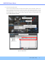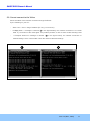
1
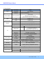
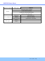
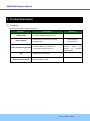
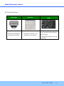
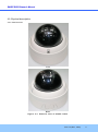
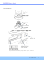
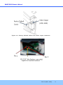
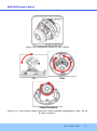
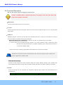
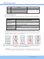
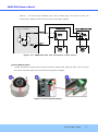
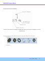
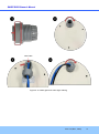
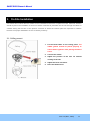
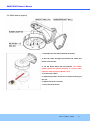
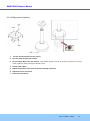
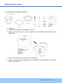
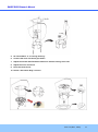
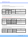
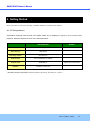
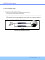
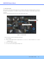
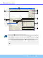
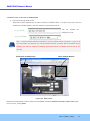
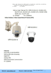
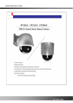
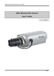
ONSIP O2D3 Owner ’s Manual ONSIP 02P3 Rev.1.0 (Nov., 2011) 1 ONSIP O2D3 Owner ’s Manual Directions Be careful not to cause any physical damage by dropping or throwing ONSIP O2D3. Especially keep the device out of reach from children. Do not disassemble ONSIP O2D3. No After Service is assumed when disassembled. Use only the power adapter provided with ONSIP O2D3. Be careful to prevent moisture or water penetration into the unit. Particular attention is needed when installing ONSIP O2D3. The screw holes for the installation screws and pipe should be maintained water tight during the whole life time of the product. All the electrical connection wires running into the unit should be prepared so that water from the outside cannot flow into the unit through the surface of the wires. Penetration of the moisture through the wire for extended period can cause malfunction of the unit or deteriorated image. Note This equipment has been tested and found to comply with the limits for a Class a digital device, pursuant to part 15 of the FCC Rules. These limits are designed to provide reasonable protection against harmful interference in a residential installation. This equipment generate, uses and can radiate radio frequency energy and, if not installed and used in accordance with the instructions, may cause harmful interference to radio communications. However, there is no guarantee that interference will not occur in a particular installation. If this equipment does cause harmful interference to radio or television reception, which can be determined by turning the equipment off and on, the user is encouraged to try to correct the interference by one or more of the following measures: Reorient or relocate the receiving antenna. Increase the separation between the equipment and receiver. Connect the equipment into and outlet on a circuit different from that to which the receiver is connected Consult the dealer or an experienced radio/TV technician for help. Rev.1.0 (Nov., 2011) 2 ONSIP O2D3 Owner ’s Manual Caution Any changes or modifications in construction of this device which are not explicitly approved by the party responsible for compliance could void the user’s authority to operate the equipment. Revision History Date Revision 2011-11-01 1.0 Details First manual revision creation. Rev.1.0 (Nov., 2011) 3 ONSIP O2D3 Owner ’s Manual Contents Contents ............................................................................................................ 4 1. Introduction................................................................................................... 5 1.1. Overview .................................................................................................................... 5 1.2. Specification ............................................................................................................... 6 1.3. Applications of ONSIP O2D3 .................................................................................... 8 2. Product Description ...................................................................................... 9 2.1. Contents ..................................................................................................................... 9 2.2. Product Preview ....................................................................................................... 10 2.3. Physical description .................................................................................................. 11 2.4. Functional Description .............................................................................................. 15 2.5. Accessories for installation ....................................................................................... 18 3. On Site Installation ..................................................................................... 20 3.1. Ceiling mount ........................................................................................................... 20 3.2. Wall mount (option) .................................................................................................. 21 3.3. Ceiling mount (option) .............................................................................................. 22 3.4. Embedded Ceiling Mount (Option) ........................................................................... 23 3.5. Installation Environment ........................................................................................... 25 4. Getting Started............................................................................................ 26 4.1. PC Requirement ....................................................................................................... 26 4.2. Quick Installation Guide............................................................................................ 27 5. Trouble Shooting ........................................................................................ 33 5.1. No power is applied .................................................................................................. 33 5.2. Cannot connect to the Video .................................................................................... 34 5.3. Windows Vista or Windows 7 ................................................................................... 35 5.4. Technical Assistance ................................................................................................ 38 Rev.1.0 (Nov., 2011) 4 ONSIP O2D3 Owner ’s Manual 1. Introduction 1.1. Overview The ONSIP O2D3 is a state-of-the-art mega-pixel, multi-codec (H.264, MJPEG) IP camera (or network camera) built with embedded software and hardware technology. It enables real time transmission of synchronized video of up to 2 M pixels and audio data. Remote clients can connect to ONSIP O2D3 for the real time video/audio data through various client solutions running on PC, PDA or mobile phones. Real time 2-way communication is available through bidirectional audio communication feature. Designed to be a stand-alone streaming audio & video transmission device, ONSIP O2D3 can be applied to various application area such as video security, remote video monitoring, distance education, video conference or internet broadcasting system. Vandal proof housing satisfying IP-66 and fan/heater will extend the application area to harsh environment of wide temperature range. Embedded PoE (Power over Ethernet, IEEE 802.3af) will enable the owner to reduce TCO (Total Cost of Ownership) by reducing on-site wiring works for the installation. Rev.1.0 (Nov., 2011) 5 ONSIP O2D3 Owner ’s Manual 1.2. Specification Category Video Sub-Category Details Compression H.264 / MJPEG Resolution * Refer to the datasheet. 3 Axis Gimbal Camera Module Mounting Gimbal (Manual Pan/Tilt adjustment & camera module rotation for rotating image) Audio Up 32 Kbps G.726 (Bi-directional) Down 64 Kbps PCM Interface RJ-45, 10/100 Mbps, PoE (802.3af) Access network Static, DHCP, PPP/PPPoE Application RTP, RTSP, SMTP, FTP, HTTP, SDP, NTP, DNS Network I/O Sensor In 1 Relay Output 1 NC, NO Selectable For alarm annunciation or remote ON/OFF control (30V, 1A) RS-232C For factory use only Mic/Line In Selectable in Admin page Line Out 1 V p-p output for amplified speaker CVBS output Temporary PoE Power over Ethernet DC Adaptor 12V DC adaptor (2 Amp) Power Supply IP66 compliant Vandal Proof housing Housing Fan/Heater Refer to Chapter 2 for operational environment Mounting Bracket, Mounting Wall, Ceiling, Embedded Motion Detection 3 zones Arbitrary shape with independent sensitivity Upgrade Firmware upgrade over IP network Administration Remote administration over IP network Web Viewer Simple viewing over internet explorer Speco-NVR Standard CMS software Client & Viewer Rev.1.0 (Nov., 2011) 6 ONSIP O2D3 Owner ’s Manual Dynamic IP support DDNS support Supported Video/Audio stream encryption ID and Password protection Security IP filtering for restricting administrative access for audio and bi-audio Time management Sync to PC Synchronize to PC Manual Manual time setting Internet Time Server Synchronize to Time Server Active-X SDK support HTTP Rev.1.0 (Nov., 2011) 7 ONSIP O2D3 Owner ’s Manual 1.3. Applications of ONSIP O2D3 Security surveillance (buildings, stores, manufacturing facilities, parking lots, banks, government facilities, military, etc.) Remote monitoring (hospitals, kindergartens, traffic, public areas, etc.) Teleconference (Bi-directional audio conference). Remote Learning, Internet broadcasting Weather and environmental observation Rev.1.0 (Nov., 2011) 8 ONSIP O2D3 Owner ’s Manual 2. Product Description 2.1. Contents The product package contains followings: Contents ONSIP O2D3 Power Adaptor Tools and Mounting Screws CD Quick Reference Guide Description Remarks IP camera ONSIP O2D3 main unit Default built in standard PoE module (IEEE802.3af) Screws, Rubber rings, Mount cap, L-type wrench, Mount cap key 12VDC Adaptor (Optional item) Basic tools and hardware (screws, rubber ring) needed for mounting ONSIP O2D3. Software & User’s Guide Quick installation guide Rev.1.0 (Nov., 2011) 9 ONSIP O2D3 Owner ’s Manual 2.2. Product Preview ONSIP O2D3 IP-Installer CMS Software (NVR) PC software to view and record Vandal Proof (Megapixel) PC software to allocate an IP Mini Dome IP Camera address to the IP Camera the A/V streaming data transmitted from IP camera. (Simultaneous support of up to 64 IP cameras) Rev.1.0 (Nov., 2011) 10 ONSIP O2D3 Owner ’s Manual 2.3. Physical description 2.3.1. External View Front Rear Figure 2-1. External view of ONSIP O2D3 Rev.1.0 (Nov., 2011) 11 ONSIP O2D3 Owner ’s Manual 2.3.2. Internal Structure Figure 2-2. Internal structure of ONSIP O2D3 Figure 2-3. Terminal Block, LAN, and DC power connector Rev.1.0 (Nov., 2011) 12 ONSIP O2D3 Owner ’s Manual Figure 2-4. Factory Default switch and Video output connector Figure 2-5. RS-232 connector Rev.1.0 (Nov., 2011) 13 ONSIP O2D3 Owner ’s Manual Figure 2-6. Adjustment knobs for the Camera Figure 2-7. 3 axis based camera position control (Manual adjustment of Pan, Tilt an d Video rotation.) Rev.1.0 (Nov., 2011) 14 ONSIP O2D3 Owner ’s Manual 2.4. Functional Description DC 12V, 2A: Power input for supplying 12V DC power. Caution: If ONSIP O2D3 is powered by PoE, do not plug in DC Jack with active DC power into DC power connector. MIC/LINE IN Connect external audio source or microphone. Line Out Connect speakers with built in amplifier. Audio from remote site is output through Line out in bi-directional audio mode. 100Base-T 100Mbps Ethernet connector (RJ-45) with PoE standard (802.3af). 2 LEDs on the Ethernet connector shows the status of ONSIP O2D3 as the followings: - Status LED (Dual Color - Red/Green): It will be lit in green or red depending on the status. Green: Green color indicates that the camera is in normal operation mode. Continuous green indicates that data transmission is possible. Blinking green means that someone is connected to ONSIP O2D3. Red: Continuous or blinking red indicates that hardware is in abnormal condition. Red/Green LED will be lit with red momentarily and it will be lit with green after a while when power is applied into ONSIP O2D3 - LINK/LAN LED (Orange) It will be lit with orange color when network cabling is all right. Blinking orange color indicates that normal data transmission is under way. Off state indicates that there is trouble in network connection. RS-232C 3 Pins on the right of the connector are assigned for RS-232 port. Please note that leftmost pin is numbered as 1. Pin Description Misc. Rev.1.0 (Nov., 2011) 15 ONSIP O2D3 Owner ’s Manual 1 Not used 2 Not used 3 RxD (Connect to TxD of the other end) 4 TxD (RxD (Connect to RxD of the other end)) 5 Ground of RS-232C For debugging & factory use only. Alarm In/Out and Audio In/Out Used for connecting alarm sensor, alarm annunciation device, microphone and speaker to ONSIP O2D3. Description LINE OUT (+) 1 V p-p audio signal output for amplified speaker. MIC/LINE GND (-) Ground for audio signals. MIC/LINE IN (+) Audio input: Can be used either for microphone or applying audio signals from other audio equipment. SENSOR IN Sensor In (+). NC/NO selectable in admin mode. SENSOR IN GND Ground for sensor RLY OUT(COM) Relay output : Circuit will be closed in alarm to indicate alarm status RLY OUT(N.O) RLY Out: Relay output is provided for connecting alarm devices or for remote on/off control of devices such as light. Relay is normal open and it will be closed upon alarm annunciation or remote on. The relay is capable of switching 30V AC/DC, 2A. For the application which needs power switching beyond this limit, use additional relay switch as shown in the right of Figure 2-8. Figure 2-8. RELAY Output connection (left: switching requirement below 30V, 2A), (r ight: switching requirement higher than 30V, 2A. Apply this connection when either voltage or current exceed the limit.) SENSOR IN: Connect external alarm sensor. Examples of sensing devices are infrared sensor, motion sensor, heat/smoke sensor, magnetic sensor, etc. Connect the two wires of the sensors to Rev.1.0 (Nov., 2011) 16 ONSIP O2D3 Owner ’s Manual “SNS In”. The sensor type (NC/NO) can be set in admin page. 10 mA can be sunk into sensor device. Multiple sensor devices can be connected in parallel. Photo Coupler NO/NCType Open CollectorType Sensor1+ Sensor Device Sensor Device Sensor1- +12V GND Sensor Power Supply Sensor Power Supply Figure 2-9. SENSOR input and connection of the sensor Factory Default Switch A switch provided for returning the IP camera to factory default state. Open the dome cover to access the switch. Press the switch for a few seconds while power is applied. Figure 2-10. Factory Default Switch Rev.1.0 (Nov., 2011) 17 ONSIP O2D3 Owner ’s Manual 2.5. Accessories for installation Figure 2-11. Accessories for installation of ONSIP O2D3. Silica gel at the right is packaged in a vacuum sealed PVC bag. It is recommended to use the Cable gland for achieving water tight cabling. Refer to the below. Component Body Cap Nut Rubber RS1 RS2 Installation Rev.1.0 (Nov., 2011) 18 ONSIP O2D3 Owner ’s Manual LAN Cable Figure 2-13. Cable gland for water tight cabling Rev.1.0 (Nov., 2011) 19 ONSIP O2D3 Owner ’s Manual 3. On Site Installation Use Cables and conduits that are suitable for the installation and that are compliant to IP-66. Particular attention should be paid in the installation so that no moisture is allowed to penetrate into the unit through the cables or conduits during the life time of the product. Products of which the internal parts are exposed to moisture because of improper installation are not covered by warranty. 3.1. Ceiling mount 1. Fix the Dome Base on the ceiling panel. The rubber gasket should be placed properly to ensure water tightness after placing the Dome Cover. 2. Connect the cables. 3. Adjust the position of the lens for desired viewing of the site. 4. Adjust the focus and zoom. 5. Place the Dome Cover. Rev.1.0 (Nov., 2011) 20 ONSIP O2D3 Owner ’s Manual 3.2. Wall mount (option) 1. Assemble the wall mount bracket assembly. 2. Run the cable through the bracket and attach the mount onto the wall. 3. Fix the Dome Base into the bracket. The rubber gasket should be placed properly to ensure water tightness after placing the Dome Cover. 4. Connect the cables. 5. Adjust the position of the lens for desired viewing of the site. 6. Adjust the focus and zoom. 7. Place the Dome Cover. Rev.1.0 (Nov., 2011) 21 ONSIP O2D3 Owner ’s Manual 3.3. Ceiling mount (option) 1. Fix the mount bracket onto the ceiling 2. Run the cable through the bracket. 3. Fix the Dome Base into the bracket. The rubber gasket should be placed properly to ensure water tightness after placing the Dome Cover. 4. Connect the cables. 5. Adjust the position of the lens for desired viewing of the site. 6. Adjust the focus and zoom. 7. Place the Dome Cover. Rev.1.0 (Nov., 2011) 22 ONSIP O2D3 Owner ’s Manual 3.4. Embedded Ceiling Mount (Option) Components Installation 1. Prepare the connecting wires and pipes for the wires. 2. Prepare a round hole (173.6 +/- 5mm in diameter) for the installation of the product on the ceiling panel. 3. Place “In Ceiling Plate” on top surface of the ceiling panel. 4. Slide in “In Ceiling Housing” through the hole and assemble “In Ceiling Plate” and “In ceiling Housing” using screws. Rev.1.0 (Nov., 2011) 23 ONSIP O2D3 Owner ’s Manual 5. Sit “Dome Base” in “In Ceiling Housing” 6. Connect the wires and finish pipe works. 7. Adjust the manual Pan/Tilt/Video rotation for desired viewing of the site. 8. Adjust the focus and zoom. 9. Place the Dome Cover 10. Set the “Decoration Ring” to finish. Rev.1.0 (Nov., 2011) 24 ONSIP O2D3 Owner ’s Manual 3.5. Installation Environment ONSIP O2D3 has fan and heater installed inside the product for wide range of environmental temperature. Refer to the tables below for the temperature range of operation. Operational temperature range Power Supply Operationalo Temperature( C) Humidity Misc (% Relative Humidity) Low High Standard PoE -15 45 8-80% DC Jack -20 45 8-80% Operational temperature (Low): Lower limit of temperature for the equipment to start running. Operational temperature (High): Upper limit of the temperature for the image sensor to provide defect free video. Starting operation in low temperature If ONSIP O2D3 is powered up under low temperature environment, the internal heater will warm up the product until the temperature inside the product reach at proper operational temperature. The table below shows time required for the heater to warm up the product. Note that warming up can take long time under low temperature below zero in Celsius. Power Supply Environmental Temperature o ( C) -10 Warming up Time (Max in minutes) -15 20 -10 5 -15 10 -20 15 10 Standard PoE DC Jack (12V, x Amp) Misc ONSIP O2D3 might noto start running under temperature below -16 C ONSIP O2D3 might noto start running under temperature below -21 C Low temperature limit If environmental temperature drops below certain limit the system will be shut down and the heater will warm up the system for protection of the ONSIP O2D3. ONSIP O2D3 will be restarted once the temperature inside the product reaches at proper working temperature, Power Supply Environmental o Temperature( C) Status of ONSIP O2D3 Misc Standard PoE -25 Shut Down System is shut down and the heater is DC Jack -25 Shut Down turned on to warm up ONSIP O2D3. Rev.1.0 (Nov., 2011) 25 ONSIP O2D3 Owner ’s Manual 4. Getting Started Brief information for first time operation of ONSIP O2D3 is provided in this chapter. 4.1. PC Requirement Audio/Video streaming data received from ONSIP O2D3 can be displayed or stored in a PC running client programs. Minimum requirement of the PC is described below: Recommended CPU Pentium IV 3G above Main Memory 1GB above Operating System * Remark Windows XP Web Browser Internet Explorer 6.0 above Graphic Card 64M above Network 100 Base-T Ethernet Higher than 1600x1200 * Operating Systems supported: Windows 2000 Professional, Windows XP / Vista / 7 Rev.1.0 (Nov., 2011) 26 ONSIP O2D3 Owner ’s Manual 4.2. Quick Installation Guide 1. Connect PC and ONSIP O2D3 to network. 1) Prepare a PC to run programs for the installation and video connection (PC is needed to assign IP address to ONSIP O2D3) 2) In the case of using PoE, connect the PC and ONSIP O2D3 to the network using one of the following ways. If your LAN Switch does not support standard PoE, connect ONSIP O2D3 as shown in dotted line in Figure 4-1. The DC power is applied through DC adaptor. DC adaptor LAN switch LAN switch with standard POE (802.3af) Figure 4-1. Power and network connection Rev.1.0 (Nov., 2011) 27 ONSIP O2D3 Owner ’s Manual 2. Install Speco-NVR Speco-NVR is a multi-channel CMS program for to IP camera or Video server. Install Speco-NVR on remote PC to connect to these products. It is needed to assign connection information to Speco-NVR program before connection. Insert the CD provided with product into the PC and install the Speco-NVR. Admin Page Button IP installer Figure 4-2. Speco-NVR Follow the sequence below for setting the IP parameter i) Run IP installer ii) Click ① in IP installer window.> Double click on ② > Fill in ④ > make a selection in ⑤ > Fill the parameters in ⑥ iii) Click on ⑨ to apply the settings. iv) You can connect to admin page by clicking on ⑩. Rev.1.0 (Nov., 2011) 28 ONSIP O2D3 Owner ’s Manual 3 1 2 9 10 5 4 7 6 8 Click on the field in ③ for sorting and rearranging the list. Select network mode that best suits from the drop down list in ⑤. You can choose either Static or ADSL and Auto (DHCP), respectively. If ADSL and Auto are selected, the fields in ⑥ is deactivated. In case of ADSL, fill the User Name and Password in ⑧ with the values provided by your ISP. If DDNS service is needed, Check at the box and fill the empty field with hostname you want in ⑦. Rev.1.0 (Nov., 2011) 29 ONSIP O2D3 Owner ’s Manual 3. Remote video connection to ONSIP O2D3 1) Connection through Web Viewer Web Viewer offers simplest way of video connection to ONSIP O2D3 . For video connection, enter the IP address of ONSIP O2D3 in the URL window of Internet Explorer as: Can [e.g.] Port 80 be omitted the default port of 80 [e.g.] Port 8080 Note : Active-X module should be installed on your PC before actual connection. If your PC is not connected to the internet, you cannot download Active-X module. Most convenient way of installing the Active-X module is installing Speco-NVR which is available from the CD or our web site. Connection to Admin Page Basic Control Buttons Video Crop Control Figure 4-3. Web Viewer Default ID and password of Admin Page are root, admin. For more detailed information, please refer to the [Configuration_Guide] Guide. Rev.1.0 (Nov., 2011) 30 ONSIP O2D3 Owner ’s Manual 2) Connection through Speco-NVR Click the camera assignment button for setting camera address. Input the description, address, Ch#, User ID, Password and port and then click the save button. After assignment procedure, you must click the SAVE button. You can see the live video when you click the live view button as below. When you exit Speco-NVR, you have to input the ID/PW, admin/1234. Details for the Speco-NVR can be found in [Speco-NVR User’s Guide]. Camera Assignment Live view Exit Program Default ID/PW: admin/1234 Camera Assignment Example Save Figure 4-4. Speco-NVR Rev.1.0 (Nov., 2011) 31 ONSIP O2D3 Owner ’s Manual 4. Additional settings through connection to the Admin Page All the parameters of new IP camera follows factory default values. For more sophisticated target application it is needed to change parameters. The admin page can be connected through ”http://IP_address:HTTP_port_number”/admin.htm It is needed to enter ID and password of the administrator. Default ID and password are root, admin. It is highly recommended to change the ID and password to prevent illegal access to the IP camera. For more detailed information, please refer to the [Configuration_Guide] Guide. Rev.1.0 (Nov., 2011) 32 ONSIP O2D3 Owner ’s Manual 5. Trouble Shooting 5.1. No power is applied In case of Standard PoE (Power over Ethernet) Power supply through standard PoE is possible only when the following conditions are met. 1. Standard PoE is supported on the product. 2. The LAN switch supports standard PoE. Make sure that both the IP camera and the LAN switch support standard PoE (IEEE 802.3af) In case of DC adaptor If PoE is not applied, the power and network connection should be made through separate cables. It is recommended to use DC adaptor supplied by provider for the feeding of the power. In case of replacing the DC power supply, make sure that the power supply meets with the power requirement of the IP camera to prevent damage or malfunction. Rev.1.0 (Nov., 2011) 33 ONSIP O2D3 Owner ’s Manual 5.2. Cannot connect to the Video Check the status of the network connection through PING test. Try the following on your PC : - Start > Run > Cmd > Ping IP address (Ex : Ping 172.16.42.51) - If “Reply from ~” message is returned ( 1 in the figure below), the network connection is in normal state. Try connection to the video again. If the problem persists, or refer to other trouble shooting notes. - If “Request timed out” message is returned. ( 2 in the figure below), the network connection or network setting is not in normal state. Check the network cable and settings. 1 2 Rev.1.0 (Nov., 2011) 34 ONSIP O2D3 Owner ’s Manual 5.3. Windows Vista or Windows 7 Windows Vista and Windows 7 users need to configure UAC (User Access Control) and Privilege Level for proper recording and still video capture in Speco-NVR and Web Viewer. <Windows Vista> 1. UAC (User Access Control) configuration 1) Double-click “User Accounts” in control panel 2) Double-click “Turn User Account Control on or off” 3) Uncheck “Use UAC to help protect your computer” 2. Privilege Level Control 1) Select “NVR” icon on the desktop 2) Click right mouse button and select “Properties” 3) Check “Privilege Level” in “Compatibility” tab Rev.1.0 (Nov., 2011) 35 ONSIP O2D3 Owner ’s Manual <Windows 7> 1. UAC (User Access Control) configuration 1) Double-click “User Accounts” in control panel 2) Double-click “Change User Account Control setting” 3) Set to “Never notify” Rev.1.0 (Nov., 2011) 36 ONSIP O2D3 Owner ’s Manual 2. Privilege Level Control 1) Select “NVR” icon on the desktop 2) Click right mouse button and select “properties” 3) Check “Privilege Level” in “Compatibility” tab Rev.1.0 (Nov., 2011) 37 ONSIP O2D3 Owner ’s Manual 5.4. Technical Assistance If you need any technical assistance, please contact your dealer. For immediate service please provide the following information. 1. Model name 2. MAC address and Registration number 3. Purchase date 4. Description of the problem 5. Error message Rev.1.0 (Nov., 2011) 38