1
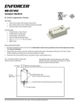
ENFORCER Voice Dialer
Troubleshooting:
Dialer will not arm/disarm
Dialer will not dial out
Unit doesn’t respond to a callback
Difficulty in activating ‘room
monitor’ by telephone remote
control
• Try re-entering the PIN number to ensure that you have
entered it correctly.
• While pressing and holding the [PROG] button, use a pen or
paper clip to press the [RESET] button on the back of the
dialer. This sets the PIN number to the default (000).Then try
to arm/disarm again.
• Make sure that the telephone line is working.
• Make sure that you have programmed at least one
telephone number into the unit and that the full number has
been stored.
• Make sure that the system is in Auto Dial mode.
• Ensure that the line to the wall jack is plugged into the
dialer’s “LINE” jack, and any phone extension connected to
the dialer is plugged into the dialer’s “TEL” jack.
• Check to see if another unit (fax or answering machine)
could be answering the call and remove the other unit.
• Adjust the call-in ring detect setting so the dialer will answer.
• Try pressing the code key again.
• Move to a quieter location as ambient noise may affect the
dialer’s ability to detect the tone signal.
Voice Dialer
Manual
NOTE: While the system can provide valuable protection to home and property when properly installed, it
cannot guarantee complete protection against intrusion. SECO-LARM is not responsible for any losses or
damage which may occur during the use of this product.
IMPORTANT: Users and installers of this product are responsible for ensuring this product complies with all
national, state, and local laws and statutes related to monitoring and recording audio and video signals.
SECO-LARM will not be held responsible for the use of this product in violation of any current laws or
statutes.
WARRANTY: This SECO-LARM product is warranted against defects in material and workmanship while
used in normal service for one (1) year from the date of sale to the original customer. SECO-LARM’s
obligation is limited to the repair or replacement of any defective part if the unit is returned, transportation
prepaid, to SECO-LARM. This Warranty is void if damage is caused by or attributed to acts of God, physical
or electrical misuse or abuse, neglect, repair or alteration, improper or abnormal usage, or faulty installation,
or if for any other reason SECO-LARM determines that such equipment is not operating properly as a result
of causes other than defects in material and workmanship. The sole obligation of SECO-LARM and the
purchaser’s exclusive remedy shall be limited to the replacement or repair only, at SECO-LARM’s option. In
no event shall SECO-LARM be liable for any special, collateral, incidental, or consequential personal or
property damage of any kind to the purchaser or anyone else.
NOTICE: The information and specifications printed in this manual are current at the time of publication.
However, the SECO-LARM policy is one of continual development and improvement. For this reason,
SECO-LARM reserves the right to change specifications without notice. SECO-LARM is also not responsible
for misprints or typographical errors.
Copyright © 2014 SECO-LARM U.S.A., Inc. All rights reserved. This material may not be reproduced or
copied, in whole or in part, without the written permission of SECO-LARM.
SECO-LARM ® U.S.A., Inc.
16842 Millikan Avenue, Irvine, CA 92606
Phone: (949) 261-2999 | (800) 662-0800
16
Website: www.seco-larm.com
Email: [email protected]
®
PIHLK1
MiE-921CPQ_141204.docx
SECO-LARM U.S.A., Inc.
Models Available
Certification
E-921CPQ
E-921KPQ
When triggered by an alarm system, the ENFORCER Voice Dialer can call up to 5 numbers and deliver
a user-recorded 20-second voice message, playing repeatedly for one minute. Each number can
contain up to 32 digits, including #, tones, and pauses. The LCD shows the number being dialed at each
stage of the dialing process. The receiver can then listen in or broadcast a message to the room
occupants or can disarm the system. The same functions are available by remote call in as well as
arming the system. The dialer includes a home mode (acting like a door chime when the owner is
present) and a panic button. The 105dB built-in siren alarm can be programmed on or off.
ENFORCER Voice Dialer
ENFORCER Voice Dialer
Summary Programming/Operation Chart:
Table of Contents:
Features ......................................................... 2
Parts List ......................................................... 3
Specifications ................................................. 3
Wiring Diagram ............................................... 3
Overview ......................................................... 4
LCD Screen Layout ........................................ 4
Installing the Voice Dialer ........................... 4~5
Programming the Voice Dialer .................... 6~9
Setting and Changing the PIN Number ...... 6
Setting Emergency Phone Numbers ...... 6~7
Deleting a Stored Phone Number ............... 7
Setting the Siren Function .......................... 7
Setting the Auto Dial Function .................... 8
Setting the Number of Auto Dial Cycles ..... 8
Setting the Number of Call-in Rings ........... 8
Setting the Entry Delay Time ...................... 9
Setting the Date and Time .......................... 9
Record and Play Back Emergency
Message ..................................................... 9
Testing the Auto Dial Function ...................... 10
Resetting the Voice Dialer ............................ 10
Line Seizure .................................................. 10
Operating the Voice Dialer ...................... 10~13
Arming and Disarming the System ..... 10~11
Panic Button Use ...................................... 11
Remote Control by Telephone ............ 11~12
Home Mode Use ....................................... 13
Low-Battery Indicator ................................ 13
View Function ........................................... 13
Tips ............................................................... 13
Program Planner ........................................... 14
FCC Part 68 .................................................. 14
Summary Programming/Operation Chart ..... 15
Also Available from SECO-LARM® ........ 15
Troubleshooting ............................................ 16
2
Current PIN [PROG] [ARM/DISARM] New PIN [ARM/DISARM] [PROG] x9
2. Setting Emergency Telephone Numbers (see pgs. 6~7)
PIN
[PROG] x2
[ARM/DISARM]
Trigger-activated alarm and dialer with user-programmable 20-second alarm message
16-Digit large display with date/time and function icons
3 Triggers (1 N.C., 2 NO/NC) for multiple zone security
Call in at any time to listen in to room, broadcast to room, arm, and disarm dialer
Listen in, broadcast messages to room, and/or disarm during dialer call out
Programmable PIN number and entry delay timing
5 Programmable emergency telephone numbers (up to 32 digits each)
Programmable auto-dialing cycle repeat times
Home mode function (acts as a door chime when user is at home)
Panic button
Back-lit keypad
Built-in flash memory to protect against system data loss in case of power failure
Touch-Tone dialing
Low-battery indicator for backup battery (battery not included)
DC power input jack (power adapter not included)
9V battery backup (battery not included)
Wall-mountable
Built-in 105dB alarm (with programmable alarm on/off)
Built-in auxiliary output for external alarm or siren
Built-in line seizure
SECO-LARM U.S.A., Inc.
[#/DOWN] or [*/UP]
Enter Phone #
[ARM/DISARM]
[PROG] x8
[DELETE/PAUSE]
[ARM/DISARM]
[PROG] x8
3. Deleting a Stored Telephone Number (see pg. 7)
PIN [PROG] x2
[ARM/DISARM]
[#/DOWN] or [*/UP]
4. Setting the Siren Function (see pg. 7)
PIN [PROG] x4 [ARM/DISARM] [#/DOWN] or [*/UP] [ARM/DISARM] [PROG] x6
5. Setting the Auto Dial Function (see pg. 8)
PIN [PROG] x5 [ARM/DISARM] [#/DOWN] or [*/UP] [ARM/DISARM] [PROG] x5
6. Setting the Number of Auto Dial Cycles (see pg. 8)
PIN [PROG] x6 [ARM/DISARM] [#/DOWN] or [*/UP] [ARM/DISARM] [PROG] x4
7. Setting the Number of Call-in Rings (see pg. 8)
PIN [PROG] x7 [ARM/DISARM] [#/DOWN] or [*/UP] [ARM/DISARM] [PROG] x3
8. Setting the Entry Delay Time (see pg. 9)
PIN [PROG] x8 [ARM/DISARM] [#/DOWN] or [*/UP] [ARM/DISARM] [PROG] x2
9. Setting the Date/Time (see pg. 9)
PIN [PROG] x9 [ARM/DISARM] [#/DOWN] or [*/UP] [ARM/DISARM] Repeat for each position
10. Record Emergency Message (see pg. 9)
PIN [REC/PLAY]
Features:
•
•
•
•
•
•
•
•
•
•
•
•
•
•
•
•
•
•
•
•
1. Setting/Changing PIN Number (see pg. 6)
[PROG] x2
11. Playback Message (see pg. 9)
Speak message (up to 20 seconds)
[REC/PLAY]
[REC/PLAY]
12. Test Auto Dial Function (see pg. 10)
(In Standby Mode)
Press and Hold [PROG]
13. Arm/Disarm System (see pgs. 10~11)
PIN [ARM/DISARM]
[#/DOWN] or [*/UP]
Check to see if number is dialed
14. Remote Control by Telephone (see pgs. 11~12)
Receive Call
Press Key Code on Telephone Keypad
Dial Voice Dialer Number Press Key Code on Telephone Keypad
15. View (see pg. 13)
Last 5 Sensor Trigger Records
(In Standby Mode) [#/DOWN]
Stored Emergency Phone Numbers (In Standby Mode)
[*UP]
16. Activate/Deactivate Home Mode
(see pg. 13)
(In Standby Mode)
[HOME]
Also Available from SECO-LARM®:
Door/Window Switches,
Magnetic Contacts, etc.
Auto Dialer
SL-1301-BAQ
Shock/Vibration Detector
Tamper Switch
Photobeam Sensor
SS-040Q
SS-072Q
E-931-S35RRQ
LED Strobe Light
E-921APQ
For a complete listing of SECO-LARM products, please visit us online at www.seco-larm.com.
SECO-LARM U.S.A., Inc.
15
ENFORCER Voice Dialer
ENFORCER Voice Dialer
Program Planner:
Parts List:
Use these charts during setup to record phone numbers and sensor locations for future reference.
It is recommended that you use a pencil during setup and redo it in ink afterwards. The user
should keep in a safe, easily accessible location and a copy should be retained by the installer.
Program: Numbers
TELEPHONE NUMBER
NUMBER
(include area code and dialer prefix as needed, add PBX
PRIORITY
pause and extension if applicable, see p. 6-7)
Date:
NAME OF PARTY TO BE REACHED
1
2
3
4
5
Installation: Triggers
TRIGGER
GENERAL DESCRIPTION
Date:
SENSOR LOCATIONS
1
2
3
FCC Part 68:
This equipment complies with Part 68 of the FCC rules and the requirements adopted by the ACTA. On the bottom of the
device of this equipment is a label that contains, among other information, a product identifier in the format
US:7M7TE02BE921CPQ and REN:0.11B for this equipment.
This equipment uses the following USOC jacks: RJ-11/RJ45/USB/Power Jacks!
A plug and jack used to connect this equipment to the premises wiring and telephone network must comply with the
applicable FCC Part 68 rules and requirements adopted by the ACTA. A compliant telephone cord and modular plug is
provided with this product. It is designed to be connected to a compatible modular jack that is also compliant. See
installation instructions for details.
REN (RINGER EQUIVALENT NUMBERS) STATEMENT
Notice: The Ringer Equivalence Number (REN) assigned to each terminal device provides an indication of the maximum
number of terminals allowed to be connected to a telephone interface. The termination on an interface may consist of any
combination of devices subject only to the requirement that the sum of the Ringer Equivalence Numbers of all the devices
does not exceed 5.
If this equipment US: 7M7TE02BE921CPQ causes harm to the telephone network, the telephone company will notify you in
advance that temporary discontinuance of service may be required. But if advance notice isn't practical, the telephone
company will notify the customer as soon as possible. Also, you will be advised of your right to file a complaint with the FCC
if you believe it is necessary.
The telephone company may make changes in its facilities, equipment, operations or procedures that could affect the
operation of the equipment. If this happens, the telephone company will provide advance notice in order for you to make
necessary modifications to maintain uninterrupted service.
If trouble is experienced with this equipment US: 7M7TE02BE921CPQ, for repair or warranty information, please contact
SmartRG, Inc. If the equipment is causing harm to the telephone network, the telephone company may request that you
disconnect the equipment until the problem is resolved.
Connection to party line service is subject to state tariffs. Contact the state public utility commission, public service
commission or corporation commission for information.
If your home has specially wired alarm equipment connected to the telephone line, ensure the installation of this US:
7M7TE02BE921CPQ does not disable your alarm equipment. If you have questions about what will disable alarm
equipment, consult your telephone company or a qualified installer.
14
SECO-LARM U.S.A., Inc.
1x
1x
3x
1x
Voice dialer unit
Remote control instruction card
Plastic wall anchors
Wall mounting template
1x
1x
3x
1x
Telephone cable
DC Plug-to-terminal block
Wall mount screws
User manual
Specifications:
Operating voltage
Standby
Dialing
Alarm On
Current draw
Max. (at 12VDC)
Relay On
Speaker On
Total
Emergency voice message length (user recorded)
Programmable emergency phone numbers
Maximum digits per telephone number
Backup battery type/life (not included)
Alarm sound level at 12" (30cm)
Triggers 1 and 2
Trigger inputs
Trigger 3
Trigger input timer
Auxiliary output current (max)
Operating temperature
Storage temperature
Weight
Dimensions
Wiring Diagram:
9~12 VDC
5mA
20mA
150mA
50mA
250mA
480mA
Up to 20s
5
32
9VDC/≈20h
≥105dB
NO/NC Trigger (auto-detected)
N.C. Trigger
≥500ms
125mA
32°~104°F (0°~40°C)
-4°~140°F (-20°~60°C)
11.15-oz (316g)
611/16"x411/16"x11/2" (170x119x38 mm)
Back Connection Area (Cover Removed)
LINE
TEL
Note: For proper operation, the telephone extension
line and wall jack line must not be reversed.
Telephone Wall Jack
Telephone Extension
-
External Alarm/Siren
+
E-964-D390Q*
or
SM-206Q*
SM-200Q*
Power Adapter
(Not Included)
Buzzer (+) O/P
Buzzer (–) O/P
CA- 161T
DC Plug-to-Terminal
Block
NO/NC Trigger in 1
NO/NC Trigger in 2
N.C. Trigger in 3
Trigger ground
* E-964-D390Q Photobeam Detectors, SM-200Q Magnetic Sensors, and SM-206Q Concealed Magnetic Sensors shown as
examples only: For other sensors and products available from SECO-LARM, please visit our website at www.seco-larm.com.
SECO-LARM U.S.A., Inc.
3
ENFORCER Voice Dialer
ENFORCER Voice Dialer
Overview:
Operating the Voice Dialer, continued:
Front
Back (Covers Removed)
LCD Display
Home Mode Use
Speaker
REC/PLAY LED
To turn off the alarm function and use the dialer as a door chime, set the dialer to “Home” mode. A
chime will ring any time one of the sensors is triggered.
LOW BATT LED
To activate the “Home” mode:
POWER LED
Numeric Keypad
1. Press the [HOME] button once. One chime will sound and the word ‘HOME’ will appear on the
LCD screen.
Microphone
2. After 60 seconds, another chime indicates that the voice dialer is now in the “Home” mode.
3. When a sensor is activated, the voice dialer will chime twice.
LINE Jack
4. If the panic button is pressed, the voice dialer will sound a 30-second alarm and start the
dialing sequence to the programmed emergency numbers.
TEL Jack
Buzzer
Terminal Block (with Trigger 3 Jumper)
DC Power Jack
Battery Receptacle
Reset Button
Alarm Triggered
Auto Dial
Time/Date
Call-Back Rings
Armed or
Siren Alarm
Disarmed
PASSWORD MEMORY LEARN
℡
CYCLE
ENTRY
Note: Arming the system deactivates the “Home” mode. After disarming, reactivate the
“Home” mode if desired.
Low-Battery (LOW BATT.) Indicator
LCD Screen Layout:
Home Mode
Activated
To deactivate the “Home” mode, simply press the [HOME] button.
When the charge level of the 9VDC backup battery (not included) is low, the “LOW BATT.” LED
will flash once every 1.5 seconds. Replace the battery in order to continue providing functionality
during a temporary disruption in power.
Note: In order to avoid potential damage due to battery leakage, do not leave a low battery in
the unit. Also, be sure to remove the battery if the unit is unused for a period of time.
View Function
To view the last 5 sensor trigger events, while in standby mode press the [#/DOWN] button.
20152015-0101-01
1212-00
TRIGGER
HOME
ARM
Note: For explanation of symbols, please see Programming the Voice Dialer on pages 6~9.
Installing the Voice Dialer:
To view stored emergency telephone numbers, while in standby mode press the [*/UP] button.
Note: After 10 seconds of inactivity, the voice dialer will automatically exit the view mode and
return to standby.
Tips:
1. Make sure that the full telephone numbers have been stored as they would normally be dialed
from a local phone.
Note: You can program the telephone numbers and voice messages prior to connecting the power
as long as the 9V battery is installed. The standby battery should provide about 20 hours of
operation.
2. The voice dialer is only suitable for single phone lines. It is not compatible with fax machines.
Note: The Voice Dialer uses EEPROM to retain memory in the event of a power loss.
3. Set the number of Call-in rings to be less than the voicemail or message answer point.
4
SECO-LARM U.S.A., Inc.
SECO-LARM U.S.A., Inc.
13
ENFORCER Voice Dialer
ENFORCER Voice Dialer
Operating the Voice Dialer, continued:
Installing the Voice Dialer, continued:
Remote Control by Telephone – Remote Control by User Call-In (Call Back), continued:
1. Select a location for the dialer near a standard electrical outlet (if user-supplied 12VDC
adapter is to be used), a telephone wall jack, and the alarm control panel, but out of sight. The
dialer should not be exposed to direct sunlight or rain, and must not be mounted near heat
sources such as radiators, heating ducts, or stoves.
C. Press one of the following function codes to control the system remotely:
Function
Listen in
Broadcast
Arm system
Disarm system
Press key code
1#
2#
5#
6#
The user should hear a “beep” in response. If not, enter the function code again.
Note: Should the user have difficulty activating functions remotely by telephone, there may
be too much ambient noise interference. Try pressing the code key again, or move to a
quieter location as ambient noise above 68dB may affect the auto dialer’s ability to detect
the tone signal.
3. FUNCTION EXPLANATIONS
LISTEN IN – Pressing [1 #] allows a user to hear sound in the room for 50 seconds. A “beep”
will sound at 30 seconds to remind the user that the listen in time will soon end. Pressing [1 #]
again will reset the 50-second period, and entering any other key code will end monitoring and
perform the function. If there is no other key press, the call will disconnect at the end of the 50
seconds.
BROADCAST – Pressing [2 #] allows a user to speak to the person in the room for 50
seconds. A ‘beep’ will sound at 30 seconds to remind the user that the time will soon end.
Pressing [2 #] again will reset the 50-second period and entering any other key code (such as
[1 #], Room Monitor) will end broadcasting and perform the other related function. If there is no
other key press, the call will disconnect at the end of the 50 seconds.
Note: Alternating between “Listen In” and “Broadcast” may be useful for a “conversation”
with the room occupant, but a user cannot speak and listen at the same time.
END CALL - Pressing [3 #] will end the call.
ARM SYSTEM – Pressing [5 #] during a user callback will arm the system, confirming with
three short “beeps,” and automatically hang up. If there are 5 rapid “beeps” after three short
“beeps,” it means a door/window is not closed. The dialer will then give 5 seconds to disarm
the system.
DISARM SYSTEM – Pressing [6 #] will disarm the system and automatically hang up.
Note: If the user enters an incorrect password or key code, the voice dialer will sound 5
“beeps” and automatically hang up.
2. For wall-mount, use the wall mounting template to
drill holes and attach 3 screws into the wall at the
desired location. For convenience, 5~6ft (1.5~2m)
5~6ft
above the floor is recommended (Fig. 1).
3. Remove the cable cover and battery cover from
the back of the voice dialer (Fig. 2).
(1.5~2m)
4. Install a 9VDC backup battery (not included).
Reattach the battery cover.
5. Connect the dialer to up to three detectors or
groups of detectors in series using the connection
terminals as shown in the wiring diagram (see pg.
3). The dialer can also be connected to three
separate alarm control panel outputs of a separate
alarm system. When Trigger 3 is used, the jumper
connection to ground must be removed.
Fig. 1
Battery
Cover
Cable
Cover
6. Power:
a. If the dialer is to be powered from the alarm
control panel, connect the alarm power outputs
to the DC Plug-to-terminal block (included) and
plug into the dialer’s DC power jack (see pg. 3).
Fig. 2
9VDC Battery
(not included)
b. If using a 12VDC adapter (not included), plug
the adapter into the dialer’s DC power jack.
7. Connect one end of the included telephone cable to
an existing Touch-Tone line wall socket, and the
other end to the dialer’s “LINE” jack. The wall socket
Fig. 3
line must be connected to the dialer’s “LINE” jack for
proper operation. Optionally, connect an extension telephone using the telephone’s cable (not
included) to the “TEL” jack (Fig. 3). Reattach the cable cover.
8. If an external alarm is desired, connect according to the wiring diagram (see pg. 3).
9. For wall installation, place the unit over the heads of the screws installed in step 2 (Fig. 1) and
slide down. Check that the unit is firmly attached and tighten or loosen the screws as needed.
10. Once all connections are made, the dialer is ready to be programmed.
12
SECO-LARM U.S.A., Inc.
SECO-LARM U.S.A., Inc.
5
ENFORCER Voice Dialer
ENFORCER Voice Dialer
Operating the Voice Dialer, continued:
Programming the Voice Dialer:
The setup mode may only be accessed when the dialer is in standby mode. If no key is pressed
within 15 seconds, the dialer will automatically exit the setup mode.
Setting and Changing the PIN Number
1. Enter the current PIN number (factory preset PIN number is ‘000’), and press the [PROG]
button once. ‘PASSWORD’ will flash on the LCD.
2. Press the [ARM/DISARM] button to accept.
3. Enter a new PIN number (3-6 digits) followed by the [ARM/DISARM] button to confirm.
4. Press the [#/DOWN] or [*/UP] button to select other setup categories or press the [PROG]
button until the programming icons disappear to exit the setup mode.
Note: If the PIN number is forgotten, press and hold the [PROG] button and use a pen or
paper clip to press the [RESET] button located near the battery receptacle cover on the back
of the unit and release. The unit will return to the factory preset PIN number (000). All other
user programmed settings except the date and time will be retained.
Setting Emergency Phone Numbers
1. Enter the PIN number and press the [PROG] button twice or until “MEMORY” flashes on the
LCD screen.
2. Press the [ARM/DISARM] button to accept.
3. Press the [#/DOWN] or [*/UP] button to select one of the number locations 1-5.
Note: The 5 number locations represent the order in which the numbers will be dialed in the
case of an alarm.
4. Enter the number to store including any area codes or dialing prefixes if needed (up to 32
digits, although only the last 16 digits can be shown on the LCD display) using the keypad
followed by the [ARM/DISARM] button to accept and store the number.
Note: If needed, add a 4-second ‘pause’ before a PBX extension number by pressing and
holding the [DEL/PAUSE] button for 2 seconds until the letter ‘F’ appears on the LCD screen,
and then continuing with the extension number as usual. A ‘#’ or ‘*’ can also be entered by
pressing, and holding for two seconds, the [#/DOWN] or [*/UP] buttons respectively. The ‘#’
sign shows as ‘┘’ and the ‘*’ sign shows as ‘└’ on the LCD screen.
Example 1 – To store a number with area code 1-214-555-2858 and an office extension 205
(where the PBX requires a 2-second pause before the extension): After scrolling to the desired
number location, enter ‘12145552858,’ press the [DEL/PAUSE] button for 2 seconds until the
letter ‘F’ appears on the LCD screen, enter ‘205’ and press the [ARM/DISARM] button.
6
SECO-LARM U.S.A., Inc.
Note: When the siren has been programmed to “SOUND OFF,” the siren will not sound and
the dialing will commence silently after the delay time has passed. When the call is answered,
the receiver will hear the user-recorded 20-second emergency message.
Note: If the voice dialer is not connected to a working telephone line, the dialer will “beep” 4
times and the siren will begin to sound without attempting to continue dialing out (this
overrides the “SOUND OFF” setting).
2. To disarm the system, enter the PIN number and press the [ARM/DISARM] button.
The dialer will sound a long “beep” and the word “ARM” will disappear from the LCD screen.
Panic Button Use
1. When the [PANIC] button is pressed, the siren will sound immediately and auto dialing will
commence without delay. If the siren has been programmed to “SOUND OFF” the siren will not
sound, but silent dialing will commence.
2. To cancel the alarm and stop auto dialing, enter the PIN number and press the [ARM/DISARM]
button. The dialer is now disarmed.
Remote Control by Telephone
The system can be remotely controlled and monitored through any Touch-Tone phone, including
mobile phones. The user may either arm or disarm the system, listen in on any activity in the room,
or broadcast a message to those in the room.
1. REMOTE CONTROL WHEN ALARM IS ACTIVATED
When an alarm has been activated and the voice dialer dials the pre-programmed emergency
numbers, the person who answers the call will hear the pre-recorded message and may press
one of the following function codes at any time to control the system remotely:
Function
Listen in
Broadcast
End call
Disarm system
Press key code
1#
2#
3#
6#
The user should hear a “beep” in response. If not, enter the function code again.
2. REMOTE CONTROL BY USER CALL-IN (CALL BACK)
A. Using a mobile phone or any Touch-Tone phone, dial the phone number that the voice
dialer is connected to. The voice dialer will answer and “beep” once after the number of
rings in the pre-programmed call-in ringer detect cycle (3, 5, 7, or 10 rings, see pg. 8).
B. Enter the PIN Number on the phone’s keypad. The dialer will “beep” twice if the correct
code has been entered. If a wrong code is entered, the dialer will disconnect automatically
and the user must dial in again.
SECO-LARM U.S.A., Inc.
11
ENFORCER Voice Dialer
ENFORCER Voice Dialer
Programming the Voice Dialer, continued:
Testing the Auto Dial Function:
To test the auto dial function, while in standby mode, press and hold the [PROG] button for at least
two seconds. When you hear a ‘beep’ tone, enter the memory location (1~5) of the number you
wish to test. The voice dialer should then dial the chosen number.
Resetting the Voice Dialer:
To reset the Voice Dialer, press and hold the [PROG] button and use a pen or paper clip to press
the [RESET] button located near the battery receptacle cover on the back of the unit and release.
The unit will return to the factory preset PIN number (000). All other user programmed settings
except the date and time will be retained.
Line Seizure:
If the telephone line that the dialer is connected to is in use, the dialer will seize the line,
disconnecting the current call, to dial out. This ensures that the dialer is able to dial emergency
numbers promptly.
Note: For proper operation, the line to the wall jack must be connected to the “LINE” jack of
the dialer. A telephone extension, if used, may be connected only to the “TEL” jack of the
dialer.
Example 2 – To store a number with area code 1-949-555-1234, and an office extension #200
(where the PBX requires a 2-second pause before the extension): After scrolling to the desired
number location, enter ‘19495551234,’ press the [DEL/PAUSE] button for 2 seconds until the
letter ‘F’ appears on the LCD screen, press the [#/DOWN] button for 2 seconds until the ‘┘’
appears on the LCD screen, enter ‘200,’ and press the [ARM/DISARM] button.
Example 3 – To store a local number 555-2858: After scrolling to the desired number location,
enter ‘5552858’ and press the [ARM/DISARM] button.
5. Repeat for the other numbers to be stored (up to 5 total).
6. Press the [#/DOWN] or [*/UP] button to select other setup categories or press the [PROG]
button until the programming icons disappear to exit the setup mode.
Note: If the dialer is programmed to call a voice pager service which requires operator assistance, the
service should be notified in advance regarding the meaning of the message. Consult local authorities
concerning the permissibility of automatically dialing their emergency numbers before programming.
Deleting a Stored Phone Number
1. Enter the PIN number and press the [PROG] button twice or until “MEMORY” flashes on the
LCD screen.
2. Press the [ARM/DISARM] button to accept.
3. Press the [#/DOWN] or [*/UP] button to select the number you wish to delete.
Operating the Voice Dialer:
4. Press the [DEL/PAUSE] button to delete the number.
Arming and Disarming the System:
1. To arm the system, enter the PIN number and press the [ARM/DISARM] button.
The dialer will sound three short “beeps” and the words “ARM” will appear on the LCD screen.
After 60 seconds, there will be a single “beep” tone to indicate that exit delay time has passed
and the alarm is now fully armed.
During the 60-second delay time after the system is armed, if the system detects trigger 3
indicating an open door or window, a “beep” tone sounds for 5 seconds, the reminder “CLOSE
PLEASE” appears on the LCD screen, and the word “TRIGGER” flashes. If, after 60 seconds,
that door or window is not closed, the alarm will sound and auto dialing will commence.
After the delay, when the system is fully armed, if a door or window connected to the alarm is
opened, the LCD screen will flash the word “TRIGGER”. After the adjustable entry delay time
has passed, the siren will begin to sound (30 seconds on and 30 seconds off) and auto dialing
will commence according to the programmed sequence and cycle times.
5. Press the [#/DOWN] or [*/UP] button to select other setup categories or press the [PROG]
button until the programming icons disappear to exit the setup mode.
Learn
This function is unused.
Setting the Siren Function
This setting allows the user to choose between an audible alarm when triggered, or a ‘silent alarm’
while dialing the emergency numbers. The factory default is “ON”.
1. Enter the PIN number and press the [PROG] button four times or until the alarm icon
(
) flashes on the LCD screen.
2. Press the [ARM/DISARM] button to accept. The dialer will “beep” once.
3. Press the [#/DOWN] or [*/UP] button to select either “SOUND ON” or “SOUND OFF” and press
the [ARM/DISARM] button to accept.
4. Press the [#/DOWN] or [*/UP] button to select other setup categories or press the [PROG]
button until the programming icons disappear to exit the setup mode.
10
SECO-LARM U.S.A., Inc.
SECO-LARM U.S.A., Inc.
7
ENFORCER Voice Dialer
ENFORCER Voice Dialer
Programming the Voice Dialer, continued:
Programming the Voice Dialer, continued:
Setting the Auto Dial Function
Setting the Entry Delay Time
The user can choose whether or not the dialer will dial the emergency numbers when triggered.
The factory default is “ON”.
This allows the user to set the length of time before the alarm will sound, to allow time to disable
the alarm after normal entry. The factory default is 20 seconds, but can be user programmed for 0,
5, 10, 15, or 20 seconds.
1. Enter the PIN number and press the [PROG] button five times or until the phone icon (℡)
flashes on the LCD screen.
2. Press the [ARM/DISARM] button to accept.
1. Enter the PIN number and press the [PROG] button eight times or until “ENTRY” flashes on
the LCD screen.
2. Press the [ARM/DISARM] button to accept.
3. Press the [#/DOWN] or [*/UP] button to select either “ON” or “OFF” and press the
[ARM/DISARM] button to accept. The dialer will “beep” once.
4. Press the [#/DOWN] or [*/UP] button to select other setup categories or press the [PROG]
button until the programming icons disappear to exit the setup mode.
Note:
1. When the dialer is in standby mode and the (℡
℡) icon is ON, the auto dial is disabled.
2. When the dialer is in standby mode and the (℡
℡) icon is OFF, the auto dial is enabled.
Setting the Number of Auto Dial Cycles
This can be set from 1~5 cycles. The factory default is 3 cycles, meaning that the voice dialer will
dial each programmed number 3 times.
1. Enter the PIN number and press the [PROG] button six times or until “CYCLE” flashes on the
LCD screen.
2. Press the [ARM/DISARM] button to accept.
3. Press the [#/DOWN] or [*/UP] button to select your choice of 1-5 cycles and press the
[ARM/DISARM] button to accept. The dialer will “beep” once.
3. Press the [#/DOWN] or [*/UP] button to select 0, 5, 10, 15, or 20 seconds and press the
[ARM/DISARM] button to accept. The dialer will “beep” once.
4. Press the [#/DOWN] or [*/UP] button to select other setup categories or press the [PROG]
button until the programming icons disappear to exit the setup mode.
Setting the Date and Time
1. Enter the PIN number and press the [PROG] button nine times or until the clock icon ()
flashes on the LCD screen.
2. Press the [ARM/DISARM] button to accept.
3. The date and time will appear on the LCD screen as 5 sets of numbers representing the year,
month, date, hour, and minute respectively. The first set of numbers (year) will be flashing,
indicating that this can now be changed.
4. Press the [#/DOWN] or [*/UP] button to select the correct number for the year and press the
[ARM/DISARM] button to accept and move to the next position. Repeat for each position until
complete.
5. Press the [PROG] button until the programming icons disappear to exit the setup mode.
4. Press the [#/DOWN] or [*/UP] button to select other setup categories or press the [PROG]
button until the programming icons disappear to exit the setup mode.
Note: Time is shown using a 24 hour clock.
Record and Play Back Emergency Message
Setting the Number of Call-in Rings
This sets the number of call-in rings after which the voice dialer will answer. The factory default is
5 rings, but can be user programmed for 3, 5, 7, or 10 rings.
1. Enter the PIN number and press the [PROG] button seven times or until the bell icon (
flashes on the LCD screen.
1. Enter the PIN number and press the [REC/PLAY] button. Speak your message into the
microphone of the voice dialer. The maximum message length is 20 seconds. When finished,
press [REC/PLAY] again.
)
Note: You may wish to include instructions for disarming the unit in your message since you
may not remember how to do so at a later date when you receive a message that the alarm
has been triggered.
3. Press the [#/DOWN] or [*/UP] button to select 3, 5, 7, or 10 and press the [ARM/DISARM]
button to accept. The dialer will “beep” once.
A suggested message could be, “{Your name}’s security alarm has been activated. Please
enter a command, 1# to monitor the room, 2# to broadcast a message to the room, 3# to end
this call, or 6# to disarm the system.”
2. Press the [ARM/DISARM] button to accept.
4. Press the [#/DOWN] or [*/UP] button to select other setup categories or press the [PROG]
button until the programming icons disappear to exit the setup mode.
2. To listen to a message, press the [REC/PLAY] button.
8
SECO-LARM U.S.A., Inc.
SECO-LARM U.S.A., Inc.
9