1
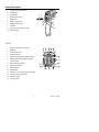
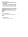
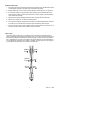
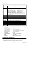
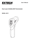
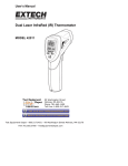
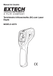
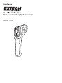
User Manual
Dual Laser InfraRed (IR) Thermometer
MODEL 42570
Introduction
Congratulations on your purchase of the Model 42570 IR Thermometer. This Infrared
thermometer measures and displays non-contact temperature readings up to
°
°
°
°
3992 F/2200 C (certified to 2000 F/1100 C) and also Type K thermocouple readings to
1370°C (2498°F). At 50”, built-in dual lasers converge to 1” target spot to insure accurate
targeting and temperature measurement. Advanced features include a USB PC interface
and software, 100ms response time, Max/Min/Ave/Diff displays adjustable emissivity and
High/Low alarms. Proper use and care of this meter will provide years of reliable service.
Warranty
EXTECH INSTRUMENTS CORPORATION (A FLIR COMPANY) warrants this instrument to be free of defects
in parts and workmanship for three years from date of shipment (a six month limited warranty applies on
sensors and cables). If it should become necessary to return the instrument for service during or beyond the
warranty period, contact the Customer Service Department at (781) 890-7440 ext. 210 for authorization or visit
our website at www.extech.com (click on ‘Contact Extech’ and go to ‘Service Department’ to request an RA
number). A Return Authorization (RA) number must be issued before any product is returned to Extech. The
sender is responsible for shipping charges, freight, insurance and proper packaging to prevent damage in
transit. This warranty does not apply to defects resulting from action of the user such as misuse, improper
wiring, operation outside of specification, improper maintenance or repair, or unauthorized modification. Extech
specifically disclaims any implied warranties or merchantability or fitness for a specific purpose and will not be
liable for any direct, indirect, incidental or consequential damages. Extech's total liability is limited to repair or
replacement of the product. The warranty set forth above is inclusive and no other warranty, whether written or
oral, is expressed or implied.
Safety
•
Use extreme caution when the laser pointer is on
•
Do not point the beam toward anyone's eye or allow
the beam to strike the eye from a reflective surface
•
Do not use the laser near explosive gases or in other
potentially explosive areas
2
42570 V1.2 8/09
Meter Description
1.
IR sensor and Laser Pointers
2.
LCD Display
3.
Down Button
4.
Measurement Trigger
5.
Mode Button
6.
Battery compartment
7.
Backlight/Laser Button
8.
Up Button
9.
Type K thermocouple input (side)
1
9
10
3
8
7
2
4
5
6
10. USB port (side)
DISPLAY
1.
SCAN, measurement in progress
2.
Bargraph
3.
Laser pointer active
4.
Power locked ON
5.
HOLD, last measurement locked in display
6.
Max/Min temperature display or memory
location display
7.
Main temperature display
8.
High/ Low limit alarm
9.
USB connection
10. Battery status
11. Emissivity or Type K or Stored value display
12. Thermocouple probe installed
13. Emissivity setting
14. Logged memory
3
42570 V1.2 8/09
Operating Instructions
IR Temperature Measurements
1. Hold the meter by its handle and point it toward the surface to be measured.
2. Pull and hold the trigger to turn the meter on and begin testing. “SCAN” and the
temperature reading will appear on the large display. The upper and lower sub-displays
will indicate values/settings previously used.
3. Release the Trigger and the reading will hold for approximately 7 seconds (“HOLD” will
appear on the LCD) after which the meter will automatically shut off. The only
exception to this is if the LOCK mode is set to ON.
The MODE button options
With the trigger pulled (SCAN displayed), Press the MODE button to view and scroll
through:
MAX :
Maximum value measured
MIN:
Minimum value measured
DIF:
Difference between the Max and Min values
AVG:
Average of the measured values
LOG:
A memory location is displayed in the small upper display and the value in that
location is displayed in the small lower display. Press the ▲ or ▼ buttons to
scroll through the locations.
TK:
With a Type K thermocouple probe connected to the meter, the probe
temperature is displayed in the small lower display.
With the trigger released (HOLD displayed), Press the MODE button to scroll through and
access the following. The selected item is indicated by a blinking icon.
Recorded data: (Press the ▲ or ▼ button to scroll through and view)
MAX
MIN
DIF
AVG
LOG
ε=
Emissivity (blinking ε=). Press the ▲ or ▼ button to set the value.
Lock mode. Press the ▲ or ▼ buttons to select ON or OFF.
High alarm ON or OFF (blinking H). Press the ▲ or ▼ button to select.
High alarm value adjustment (blinking H and
set the value.
). Press the ▲ or ▼ button to
Low alarm ON or OFF (blinking L). Press the ▲ or ▼ button to select.
Low alarm value adjustment (blinking L and
set the value.
). Press the ▲ or ▼ button to
°C or °F Temperature units. Press the ▲ or ▼ button to select.
4
42570 V1.2 8/09
Dual Laser Pointer and Backlight Button
The dual laser pointers are designed to cross at a distance of 50” (76cm). The spot size at
this distance is a 1” diameter and this is the recommended distance to target for most
measurements. To turn the lasers on/off:
1. Press and Hold the Trigger
).
2. While SCAN is on the display, press and release the backlight/laser button (
Either the backlight or laser pointers will change status (On/Off). Repeat this until the
desired conditions are set. The laser icon
function is enabled.
will appear in the LCD when the laser
3. The status of the functions will be stored in memory and will remain as the default
“turn-on” condition until changed.
High and Low Alarm Feature
When either programmed alarm (high or low) point is reached the meter will alert the user
via an audible beep and a blinking LCD display icon. The alarm limit is set and the feature
is enabled/disabled using the MODE button. The setting is stored and memory and will
remain as the “turn-on” condition until changed.
Temperature Units
The temperature units can be set to °F or °C. The selection is made using the MODE
button.
Lock feature
The LOCK feature disables the Auto Power Off feature for the period of use when
selected. The feature is useful for long term temperature monitoring and hands free use.
The meter will revert to auto power off if the trigger is pressed during a locked scan. The
selection is made using the MODE button.
Over-range Indication
If the temperature measurement exceeds the specified temperature range, the
thermometer will display dashes in place of a temperature reading.
USB Function
The supplied software and cable are used to transmitt the IR and Type K measurement
data to a PC via USB.
To Turn-on or Shut-off the USB function:
1.
With MAX, MIN, DIF, or AVG displayed, press the LIGHT/LASER button until “USB”
sign appears in the right lower corner of the LCD. USB is active.
2.
Press the LIGHT/LASER button again until “USB” disappears. The USB function is
off.
Refer to the help file in the software for operational details.
5
42570 V1.2 8/09
Battery Replacement
When the low battery symbol
appears on the display, replace
the meter’s battery (9V). The battery compartment is located
behind the panel that surrounds the meter’s trigger. Open the
compartment by pressing the release button (1) and then pulling
the panel (2) down from the trigger area. Replace the 9V battery
and close the battery compartment cover.
1
2
Data Logger
Storing Data: The thermometer is capable of storing up to 100
data points.
Infrared: To store data from an infrared reading,
1.
Pull and Hold the trigger
2.
Press the MODE button until LOG appears in the lower left corner of the display; a
log location number will be displayed. If no temperature has been recorded in the
displayed LOG location, 4 dashes will appear in the lower right corner.
3.
Aim the unit at the target area you want to record, and press the laser/backlight
button. The recorded temperature will appear in the lower right corner.
4.
To select another log location, press the up and down keys.
Recalling Data: To recall stored data after the unit shuts off,
1.
Press the MODE button until LOG appears in the lower left corner. A LOG location
number will be shown below LOG, and the stored temperature for that location will
be display.
2.
To move to another LOG location, press the UP and Down keys.
Log Clear Function: To clear the memory,
The “Log clear” function allows you to quickly clear all logged data points. This function
can only be used when the unit is in the LOG mode.
1.
While in LOG mode, press the trigger, and then press the “down” arrow button until
LOG location “0” is displayed. Note: This can only be done when the trigger is
pulled. LOG location “0”cannot be accessed, by using the “up” arrow button.
2.
When LOG location “0” shows in the display, press and release the laser/backlight
button, then press and release the up arrow key. A tone will sound, and the LOG
location will automatically change to “1”, signifying that all data locations have been
cleared.
6
42570 V1.2 8/09
IR Measurement Notes
1. The object under test should be larger than the spot (target) size calculated by the field
of view diagram (printed on the side of the meter and in this guide).
2. Before measuring, be sure to clean surfaces that are covered with frost, oil, grime, etc.
3. If an object's surface is highly reflective, apply masking tape or flat black paint to the
surface before measuring. Allow time for the paint or tape to adjust to the temperature
of the surface it is covering.
4. Measurements through transparent surfaces such as glass will not be accurate.
5. Steam, dust, smoke, etc. can obscure measurements.
6. The meter automatically compensates for deviations in ambient temperature. However,
it can take up to 30 minutes for the meter to adjust to extremely wide changes.
7. To find a hot spot, aim the meter outside the area of interest then scan across (in an up
and down or side to side motion) until the hot spot is located.
Field of View
The meter’s field of view is 50:1. For example, if the meter is 50 inches from the target
(spot), the diameter of the target must be greater than 1 inch. Other distances are shown in
the field of view diagram. Measurements should normally be made as close as possible to
the 1” spot distance. The meter can measure from longer distances, but the measurement
may be affected by external sources of light. In addition, the spot size may be so large that
it encompasses surface areas not intended to be measured.
@300cm
5cm
@100”
2”
@150cm
2.5cm
@50”
1”
@75cm
1.25cm
@25”
0.5”
7
42570 V1.2 8/09
Specifications
InfraRed Thermometer
o
o
o
o
Range
-58 to 3992 F (-50 to 2200 C)(typical spec only >1832 F/1000 C)
Resolution
0.1 < 1000 , 1 ≥ 1000
Accuracy
-58°F to -10°F(-50°C to -23°C)
±14°F/7°C (Typical)
-10°F to 28°F(-23°C to -2°C)
±8°F/4°C
28°F to 200°F (-2°C to 94°C)
±4.5°F/2.5°C
200°F to 400°F (94°C to 204°C)
±(1.0%rdg + 2°F/1°C)
400°F to 800°F (204°C to 426°C)
±(1.5%rdg + 2°F/1°C)
800°F to 1832°F (426°C to 1000°C) ±(3%rdg +2°F/1°C)
1832 to 3992°F (1000°C to 2200°C) ±(5%rdg +4°F/2°C)(typical only)
Note: Accuracy is specified for the following ambient temperature range:
73 to 77°F (23 to 25°C)
Emissivity
0.10 to 1.00 adjustable
Field of View
D/S = Approx. 50:1 ratio (D = distance; S = spot or target)
Laser pointer
Dual, Class 2 laser < 1mW power; Wavelength is 630 to 670nm
IR Spectral
response
8 to 14 μm (wavelength)
Repeatability
± 0.5% of reading or ± 1.8 F (1 C) whichever is greater
o
o
o
o
o
o
Thermocouple Thermometer (Type K)
Range
-50 to 1370°C(-58°F to 2498°F)
Resolution
0.1 °C(0.1°F)<1000, 1°C(1°F)>1000
Accuracy
-50 to 1000°C (-58 to 1832°F): ± 1.5% of reading + 3°C (±5°F)
1000 to 1370°C (1832°F to 2498°F): ± 1.5% of reading + 2°C (±3.6°F)
General Specifications
Display
Backlit LCD display with function indicators
Response time
100ms
Over range indication
“---------“
Operating Temperature
32 F to 122 F (0 C to 50 C)
Operating Humidity
10% to 90%RH operating, <80%RH storage.
Storage Temperature
14 to 140 F (-10 to 60 C)
Power Supply
9V battery
o
o
o
o
o
o
Automatic Power Off
7 seconds, with LOCK to disable
Weight
11.3 oz. / 320g
Dimensions
8 x 6.1 x 2” (204 x 155 x 52mm)
Calibration and Repair Services
Extech offers repair and calibration services for the products we sell. Extech also
provides NIST certification for most products. Call the Customer Service Department for
information on calibration services available for this product. Extech recommends that
annual calibrations be performed to verify meter performance and accuracy.
8
42570 V1.2 8/09
Support line (781) 890-7440
Technical support: Extension 200; E-mail: [email protected]
Repair & Returns: Extension 210; E-mail: [email protected]
Product specifications subject to change without notice
For the latest version of this User’s Guide, Software updates, and other
up-to-the-minute product information, visit our website: www.extech.com
Extech Instruments Corporation, 285 Bear Hill Rd., Waltham, MA 02451
Copyright © 2009 Extech Instruments Corporation (a FLIR company)
All rights reserved including the right of reproduction in whole or in part in any form.
9
42570 V1.2 8/09