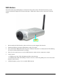
1
MPEG-4 Ethernet/ Wireless Network Camera User Manual CONTENTS About This User’s Guide .............................................................................................................................. iii Before You Start ........................................................................................................................................... iii Packing List .................................................................................................................................................. iii System Requirements.................................................................................................................................... iv Default Settings............................................................................................................................................. iv INTRODUCTION ......................................................................................................................... 5 Features and Benefits ..................................................................................................................................... 5 LED Indicators............................................................................................................................................... 6 Rear Panel ...................................................................................................................................................... 7 WPS Button ................................................................................................................................................... 8 INSTALLING THE CAMERA....................................................................................................... 9 Attach Camera to Stand........................................................................................................................... 9 Connect Ethernet Cable........................................................................................................................... 9 Connect Power and Power On Camera ................................................................................................ 10 Reset Camera ............................................................................................................................................... 10 CAMERA APPLICATIONS........................................................................................................ 11 Home Applications ...................................................................................................................................... 11 SOHO Applications ..................................................................................................................................... 12 Enterprise Applications................................................................................................................................ 12 USING THE CAMERA WEB MANAGER .................................................................................. 13 Accessing the Camera Video Display .................................................................................................. 13 Login ............................................................................................................................................................ 14 Web Manager and Live Video Display Page............................................................................................... 14 Live Video Display User Interface .............................................................................................................. 15 Camera Configuration Setup ................................................................................................................. 17 Network Settings.......................................................................................................................................... 18 Wireless Setup ............................................................................................................................................. 20 Image Setup ................................................................................................................................................. 21 Video and Audio Settings ............................................................................................................................ 22 Motion Detection ......................................................................................................................................... 23 Time and Date.............................................................................................................................................. 24 Recording Preferences ................................................................................................................................. 25 Snapshot Preferences ................................................................................................................................... 26 System Configuration ............................................................................................................................ 27 Back Up and Restore Camera Settings ........................................................................................................ 28 Firmware Upgrade ....................................................................................................................................... 28 Device Information ...................................................................................................................................... 29 Camera Log.................................................................................................................................................. 29 IPVIEW PRO PLD ..................................................................................................................... 30 Installation.................................................................................................................................................... 31 Getting Started ............................................................................................................................................. 33 Item Feature ................................................................................................................................................. 34 Using IPView Pro PLD................................................................................................................................ 36 Viewing a Camera........................................................................................................................................ 38 Recording Video .......................................................................................................................................... 38 Playing Recorded Video .............................................................................................................................. 38 Configuring IPView System Settings.................................................................................................... 39 Camera Configuration.................................................................................................................................. 40 Proxy Server................................................................................................................................................. 41 Recording Configuration.............................................................................................................................. 42 Others........................................................................................................................................................... 44 Account ........................................................................................................................................................ 44 About............................................................................................................................................................ 45 FFDSHOW .................................................................................................................................. 46 Installing FFdshow ................................................................................................................................. 46 Playing the Video.................................................................................................................................... 50 TECHNICAL SPECIFICATIONS ............................................................................................... 51 CS-633W Wireless/Ethernet Network Camera About This User’s Guide This user’s guide provides instructions on how to install the MPEG 4 Network camera and use it for camera monitoring applications. Camera monitor applications are accessible through an Ethernet or 802.11g wireless local network. Before You Start Please read and make sure you understand all the prerequisites for proper installation of your new VLAN Switch. Have all the necessary information and equipment on hand before beginning the installation. Packing List Open the shipping carton and carefully remove all items. In addition to this Manual, ascertain that you have: • One Wireless/ Ethernet Network Camera • One Camera Stand • One Antenna (for wireless model) • One Power Adapter • One Ethernet Cable • One Installation CD-ROM containing IPView Pro PLD application installer and Setup Wizard PLD. If any of the above items are missing, please contact your reseller. CAUTION: The Internet Camera must be used with the power adapter included with the device. iii CS-633W Wireless/Ethernet Network Camera System Requirements Computer • CPU: Intel Celeron 1.1 GHz or above • Memory: 128 MB or above • VGA Resolution: 800 x 600 or above • 10BASE-T Ethernet or 100BASE-TX Fast Ethernet • CD-ROM Drive for Setup Wizard PLD on Installation CD-ROM • IPView Pro PLD Application Users must use Microsoft® Windows® 98SE, ME, 2000 or XP operating system. Network • Local Area Network: 10Base-T Ethernet or 100Base-TX Fast Ethernet • Wireless Local Area Network (wireless model): IEEE 802.11g Wireless LAN Default Settings Use the default settings to access the web-based management software and live video display. Default configuration settings Username This is the Username you will be prompted to enter when you access the MEPG 4 Network camera configuration screens using a Web browser. The default Username is admin. Password This is the Password you will be prompted to enter when you access the configuration windows using a Web browser. The default Password is admin. IP address The camera has a default IP address that is used if no DHCP server is detected active on the network. If your network does not have DHCP service, that is, if IP settings are NOT obtained automatically, or if you connect directly to the camera from your computer, the camera will default to IP address 192.168.0.20, make sure your computer is configured to belong to the 192.168.0.X subnet if using the default IP address of the camera. Subnet Mask The default subnet mask used if there is no DHCP service detected is 255.255.255.0. iv 1 Introduction The MPEG-4 Network Camera transmits live real-time high-quality MPEG-4 video through an Ethernet network or 802.11g wireless LAN* useful for remote monitoring applications. The live video can be viewed remotely and managed through the network from any computer connected to the network. A built-in microphone allows synchronized audio and high-quality video monitoring. * For wireless model. Features and Benefits Easy to use - The MPEG-4 Internet Camera is a standalone system with built-in CPU, no special hardware (such as a PC frame capture card) or software required. The camera supports DirectX 9.0; therefore, the only requirement you need is the web browser software such as Internet Explorer 6.0 or above. Once you have a valid IP Address, just connect it and you can view the picture and receive sound from your camera. In addition, the camera’s stand allows you to adjust the camera for optimal viewing angle. Support variety of platforms - The camera supports TCP/IP networking, SMTP e-mail, HTTP and other Internet related protocols. It can be utilized in a mixed operating system environment, including Windows 98SE/ME/ 2000/XP. Moreover, it can be integrated easily into other www/ Intranet applications. Web configuration - Applying a standard web browser, the administrator can configure and manage the camera directly from its own web page via the Intranet or Internet. Up to 20 user accounts are permitted with privilege setting controlled by the administrator. Remote Utility - The powerful IPView Pro PLD application assigns the administrator with a pre-defined user ID and password, allowing the administrator to modify the camera settings from the remote site via Intranet or Internet. When new firmware is available, you can also upgrade remotely over the network for added convenience. Users are also allowed to monitor the image, and take snapshots. Broad Range of Applications - With today’s high-speed Internet services, the camera can provide the ideal solution for live video images over the Intranet or Internet for remote monitoring. The camera allows remote access from a web browser for live image viewing, and allows the administrator to manage and control the camera anywhere and anytime in the world. Apply the camera to monitor various objects and places such as homes, offices, banks, hospitals, child-care centers, amusement parks and other varieties of industrial and public monitoring. The camera can also be used for intruder detection; in addition, it can capture still images for archiving and many more applications. 5 LED Indicators Link Power The LED indicators on the front panel include the Power, Status, WAN, and LAN for the Ethernet ports. Power:A steady blue light indicates the Camera is powered on. The camera is not receiving power if the LED is dark. Pwr WPS:Push WPS button over 3 sec and LED blinking 0.5 time/sec. success: Lighting and then reboot directly. Fail: blinking 0.1 time/sec for 10 sec and then reboot directly. LNK Link:A steady orange light indicates the Ethernet link is valid. The LED will blink when data is transmitted or received through the Ethernet link. 6 Rear Panel Connect the power adapter cord and network cables on the rear panel. The reset button is also located on the back of the device. Reset Button Power Connector Ethernet Port Antenna Post Audio Out Ethernet Port Connect to Ethernet LAN. The port is auto MDI-II/MDI-X and auto-negotiation for port speed. Power Connector Connect power adapter shipped with the camera and plug into suitable power source. Antenna Post On the wireless model, a threaded post is used for attaching the antenna. Audio Line Out The audio line out recepticle is a mini-plug audio connection for speakers. Reset Button Use to reset device to factory default settings including IP address and administrator user name and password. 7 WPS Button Wi-Fi Protected Setup (WPS) button is located at the side of the camera. The function must to go with wireless stations that support Wi-Fi Protected Setup, or WPS and it makes wireless connection to the AP simple. WPS 1. Before enable the WPS function, make sure the access point supports this function. 2. Enable the WPS by pressing the WPS button at the access point. 3. Press and hold the WPS button until the power LED turns off (about 5 seconds),then the LED blinking 0.5 time/sec means WPS function is working. 4. Wait for 120 seconds at most to see the WPS function is make wireless connection is simple. 5. In the Camera: If WPS success,Pwr LED will lighting and then reboot directly. If WPS fail,Pwr LED will blinking 0.1 time/sec for 10 sec after doing WPS process for 120 seconds and then reboot directly. 6. If WPS fail,please go step 1-4 to re-enable WPS function 8 2 Installing the Camera The camera should be attached to the stand included in the package. The camera stand can be mounted on a flat surface using the three screw holes on the base of the stand. The camera is intended for indoor use. The camera, the power adapter and power source should be protected from water and moisture, excessive heat, direct sunlight and cold. Make sure the power adapter and cord and Ethernet cable are safely arranged so they do not create a tripping hazard and will not be disturbed by people or objects moving past. Attach Camera to Stand The camera is shipped with a camera stand. The swivel ball screw head on the stand can be attached to the bottom screw hole of camera. The swivel ball mount allows the camera to be pointed in a direction and fixed in position. Three holes on the base of the camera stand are used to securely attach the stand to a wall or ceiling. Connect Ethernet Cable Insert an Ethernet cable into the Ethernet port to connect the camera to the local area network. 9 Connect Power and Power On Camera Attach the external power supply to the DC power input connector located on the rear panel of camera, then connect it toa suitable power source. Check the Power LED indicator on the front of the camera to make sure it is powered on. CAUTION: The Camera must be used with the power adapter included with the device. Reset Camera To reset the system settings to factory defaults, please follow these steps: 1. Leave the camera powered on, do not disconnect the power. 2. Press the reset button and hold (use a paper-clip). See the back panel illustration above to view the location of the reset button. 3. Keep the button pressed about 6 seconds. 4. Release the button. The camera will then automatically reboot itself. Upon restarting the camera loads the factory default configuration settings including the default IP address 192.168.0.20 and a subnet mask 255.255.255.0. The adminstrator’s default user name is admin and the password is admin. 10 3 Camera Applications The camera can be applied in wide variety of applications. With the built-in CPU, it can work as a standalone system that provides a web-based solution transmitting high quality video images and sounds for monitoring purposes. It can be managed remotely, accessed and controlled from any PC desktop over the Intranet or Internet via a web browser. With the easy installation procedure, real-time live images will be available. Applications: Use a web browser to monitor local and remote places and objects such as construction sites, hospitals, amusement parks, schools and day-care centers etc. View image from IPView Pro PLD. Configure the camera to save image or send-mail messages with a short video file. Home Applications MPEG4 Internet Camera ADSL/Cable Modem Wireless Video Server Wireless Video Server MPEG4 Internet Camera MPEG4 Wireless Internet Camera 11 SOHO Applications MPEG4 Internet Camera MPEG4 Wireless Internet Camera MPEG4 Internet Camera Enterprise Applications MPEG4 Internet Camera MPEG4 Internet Camera MPEG4 Wireless Internet Camera 12 4 Using the Camera Web Manager The camera is easy to use and manage. Use a normal web browser to access the camera’s live video display, as well as the configuration software. It is recommended to check and make sure the computer can access and use the camera before placing it in the location where it will be used, especially if it is mounted to a ceiling or other area that is difficult to physically access. For the initial setup, use the Setup Wizard PLD program located on the CD-ROM included with the camera. Use the Setup Wizard PLD to assign an IP address and other network settings. Once the camera has an IP address, follow the instructions below to access the camera’s web management interface used to manage the camera and for video display. Accessing the Camera Video Display If the camera is used on a network with an active DHCP server, the camera will detect it and obtain an IP address. If you are using the camera on a network with a DHCP server it is necessary to first determine what the IP address of camera is is. To do this, follow the instructions in the Quick Installation Guide to launch the Setup Wizard PLD software utility used with the MPEG-4 Network Camera. If your network does not use a DHCP server, the camera will use a default IP address of 192.168.0.20. Use this address to access the web-based management software. Use a web browser and type in http:// followed by the default IP address, 192.168.0.20 in the address bar of the browser and press the Enter key. The URL in the address bar should read: http://192.168.0.20 If the login dialog does not appear, check the proxy server settings on your browser. NOTE: The wrong proxy server settings on your browser can prevent connection to the web manager. If you are having trouble connecting to the web interface of the VLAN Switch, configure the proxy settings to bypass the proxy server or disable use of proxy servers and try to connect again. To check proxy setting for Windows Internet Explorer: 1. In Windows, click on the Start button, go to Settings and choose Control Panel. 2. In the Control Panel window, double-click on the Internet Options icon. (Alternatively you can access this Internet Options menu using the Tools pull-down menu in Internet Explorer.) 3. Click the Connections tab and click on the LAN Settings button. 4. Verify that the “Use proxy server” option is NOT checked. If it is checked, click in the checked box to deselect the option and click OK. 13 Login The login dialog appears when accessing the camera. Login Type the default user name “admin”, default password “admin” and click on the OK button to access the camera’s management interface. Web Manager and Live Video Display Page The live video display appears after successful logging in to the web manager. Camera video display in web manager 14 Live Video Display User Interface The web manager’s live video page presents icons at the bottom used to change the display size, control snapshot and recording of video and audio controls. Links to other management menus are located at the top right porting of the interface. Click the SETUP link to view menus used to configure various camera settings including advanced video, wireless and network configuration settings. Click the SYSTEM link to view menus used for device management, firmware upgrades, device logs, device reset and configuration settings back up. Video display page Zoom In / Zoom out Move your mouse to the video display area and the cursor becomes a magnifying glass symbol. Then zoom in or out using the left and right button on your mouse. Use the drop down menu to change the language of the web manager interface. The icons within the user interface are explained below. 15 Change display size Click on icons to change video display size. The yellow icon shows which size is currently being used. Record and capture Use the camera icon to take a snapshot of the video display. This will immediately cause the screen capture or snapshot to appear on the desktop in a new browser window. Use the Record (REC) icon to begin recording to the local hard disk. In order to do either of these however, first click on the file icon to locate the file where the snapshot or video recording is to be stored. A file is created automatically in My Documents for this purpose in Windows operating systems; or choose a different file. The REC icon becomes yellow while recording is active. Audio controls Use the headphones icon to activate or deactivate audio monitoring or to turn the audio speaker on and off. The icon appears yellow when the feature is active. Æ Motion detection indicator The motion detection icon appears yellow when motion is detected in the zone previously configured for motion detection. Motion detection must be configured in the Motion Detection menu located in the Setup Menu directory (see details below). Recording indicator This appears yellow while the video display is being recorded. Æ 16 Camera Configuration Setup Click the SETUP link to view the menus in the Setup Menu directory. These menus are used to configure network settings, wireless, video and other settings for the camera. Setup Wizard PLD menu To configure the camera with the web manager’s Setup Wizard PLD, click the Next button and follow the instructions in the menus to configure network, time and name settings. To configure these settings without using the wizard, click on the link for the settings to be configured to view the configuration menu. These menus are presented and described in the pages that follow. 17 Network Settings Click the Network Setup link to view menus for IP network settings, PPPoE configuration, DDNS and HTTP or RTSP port configuration. Network Setup menus LAN IP Settings The camera’s IP settings can be configured as a DHCP client to obtain IP settings automatically, or configure static IP settings as needed for the private network. To use IP settings automatically obtained from a DHCP server on the network, select the DHCP Connection option. For manually entered or static IP settings, choose the Static IP Address option and type an IP Address unique on the LAN, appropriate Subnet Mask, Default Gateway address and Primary and Secondary DNS server IP address (for example, used for functions that require Internet access and DNS service such as SNTP with a named server). Click the OK button at the bottom of the web page to change and save the IP settings. 18 PPPoE For PPPoE client Internet access, click to select the Enable PPPoE box and enter the user name and password used for the PPPoE connection. Click the OK button at the bottom of the web page to apply the PPPoE account settings. DDNS If a Dynamic DNS account has been setup, use the DDNS menu to enter account information. DDNS menu Click the Enable DDNS option and enter DDNS account information in the available entry fields. Click the OK button at the bottom of the web page to apply the DDNS configuration. Port Detail Use the Port Detail Settings menu to change the port used for HTTP web access or RSTP streaming access to the camera’s video output. Port Detail settings menu 19 Wireless Setup The Wireless Network Camera supports normal wireless LAN functions for 802.11g wireless networks including WEP or WPA basic security settings. The wireless camera also supports WPS (Wi-Fi Protected Setup) for quick and easy wireless security setup. Wireless Configurationn menu Click to select the Enable Wireless box to conduct an automatic Site Survey and detect available SSID. Select the desired SSID from the pull-down menu. SSID can also be configured manually by typing in the name of the SSID in the entry field. Choose the Wireless Mode to determine if the wireless opertates in Infrastructure (default) or Ad-Hoc mode. Select the Channel used or use the Auto (default) option to find the channel used for the selected SSID. Choose the preferred Authentication and Encryption used. Configure WEP, WPA-PSK or WPA2-PSK settings to suit the security environment of your wireless LAN and click the OK button to implement the new security settings. Site Survey The pull-down menu displays available networks. To connect one wireless network, scroll up and down in the list and highlight to select the desired network and it is listed in the SSID field. Click Rescan to conduct a new search available networks. SSID SSID (Service Set Identity) is the name assigned to the wireless network. It will auto-detect and display the SSID of wireless network connected in this box. This default setting will let the camera connect to ANY access point under the infrastructure network mode. Wireless Mode Choose Infrastructure (default) if there is an available wireless access point within range or Ad-Hoc mode to access the camera directly from another computer such as a wireless laptop. Channel This pull-down menu provides the wireless channel for communication. Select the appropriate channel from the list provided depending on the regulatory region where the unit is sold or use the Auto option. WEP Authentication Open communicates the key across the network. Shared allows communication only with other devices with identical WEP Encryption settings. Enter the key used for WEP encryption in the Key field. A Pre-Shared Key is used to identify each other in the network. If encryption is enabled on the router or access point in the network, enter the same encryption key in the Key field to access the device in camera. WPA Authentication Use WPA-PSK or WPA2-PSK select the preferred Encryption type AES or TKIP, and enter a Key of the correct character length. 20 Image Setup Use the Image Setup configuration to optimaize the live video display. Video image settings Brightness Adjust the brightness level. The value range is from 0 - 100, and the default setting is 26. Contrast Adjust the contrast level. The value range is from 0 – 100 increments of 20, and the default setting is 100. Flip Use this to flip the image upside down. This is used with the Mirror option if the camera is mounted in a hanging position as from a ceiling. Saturation Adjust the color saturation level. The value range is from 0 – 100 increments of 20, and the default setting is 60. Frequency Select the proper frequency (50Hz or 60Hz) to eliminate flicker or use the Auto select. B/W This option changes the display to a black and white only display (that is, no color is displayed in the video). Mirror Use this to produce a mirror image display. This is used with the Flip option if the camera is mounted in a hanging position, as from a ceiling. 21 Video and Audio Settings Use this menu to optimize video resolution, frame rate and bit rate settings on the camera. Video output can be adjusted for use on Microsoft Internet Explorer in the IE Browser Video Setup menu or other broswers in the Non-IE Browser Video Setup menu. The Mobile Video Setup is used to adjust settings for mobile camera use. Advanced video and audio settings Use Night Mode for use in low light situations. The Audio Setup menu is used to enable and disable microphone and speaker as well as adjust volume of each. 22 Motion Detection Motion detection is used to trigger video recoeding when motion is detected in a designated portion of the video display. To designate a portion of the display used for motion detection, choose the Draw motion area option and use the mouse and left mouse button to draw a rectangular area. The drawn area appears as a red box on the display in the Motion Dection menu. Click the Enable Video Motion box to check mark it and click the OK button. Sensitivity level can be set by typing a value from 0 – 100, with 100 being the most sensitive. Motion detection menu To remove the drawn motion area, select the Erase motion area option and click OK. 23 Time and Date Use the Time and Date menu to set the camera’s time settings manually, from the computer’s time or use a network time server (NTP server). Time and date menu Choose the time and date settings including Daylight Saving adjustment if applicable. Click the OK button to apply the time settings. 24 Recording Preferences The Recording Setup menu is used to determine when and how digital video recordings are handled. Recordings can be saved to a shared folder on a secure server. The recording can be scheduled or event based using motion detection as the trigger. One option allows resolution of recordings to be adjusted down to use less hard disk space. Recording can be stopped when the hard disk is full or choose the option to overwrite the disk to replace old recordings. Recording preferences menu 25 Snapshot Preferences The Trigger menu is used to determine when and how digital images from snapshots are handled. Use motion detection to trigger a snapshot and email it to the account configured here. Alternatively, the images can be sent to an FTP server. Configure FTP Server and E-Mail Address information and click to checkmark either or both options to use. Snapshot Trigger menu 26 System Configuration The System configuration menus include the Device Management menu. Device Managment menu Change the camera password and enter user account information in the Device Management menu. Users can be removed by selecting the name in the User List and clicking the Delete button. 27 Back Up and Restore Camera Settings To save configuration settigns for the camera to a file on a local hard disk, click the Save Configuraiton. A prompt appears to confirm that you want to save the file. Choose the location and save the file to load the same settings. Save System Settings/Restore/Reboot menu To load a previously saved configuration settings file, click the Browse button to Load From Local Hard Drive to locate the file, then click the Load Configuration button. It will take a few seconds to load the new settings, then the camera will restart. To restore the camera to the factory default configuration settings, click the Restore Factory Defaults button. A prompt appears to confirm that you want to restore the default settigns. Click OK to restore the settings. To performa a simple restart of the camera click the Reboot Device button. Firmware Upgrade To upgrade the camera firmware, make sure the correct firmware file is located on your computer. Click the Browse button to locate the file, then click the Upload button to load the file. It will take several seconds to load the firmware and restart the camera. Firmware Upgrade menu 28 Device Information Network information, MAC address and firmware version is displayed in the Device Information display. Device Information display Camera Log Click the Log link to view the camera’s current log. To save the log in simple text form on your computer, click the Download button. Click Clear to delete all entries in the log. Camera Log 29 5 IPView Pro PLD The camera is shipped with IPView Pro PLD software. Install the program on any Windows computer to access the camera display. IPView supports many of the functions available in the web interface video display. Up to sixteen separate cameras video displays can be viewed at a time. IPView multidisplay interface 30 Installation 1. Insert the CD-ROM into the CD-ROM drive to initiate the auto-run program. The menu screen will appear as below: 2. Click the IPView Pro PLD item to activate the InstallShield Wizard. Click Next in the welcome screen. 3. Read and accept the License Agreement; then, click Yes. 31 4. Choose the destination location. If no specific requirement, leave the default setting and click Next. 5. The InstallShield Wizard starts to install the software, and the progress bar indicates the installation is proceeding. 6. If you use Windows® 2000/XP, it will appear a Digital Signature warning screen. Click Continue Anyway (Windows® XP) or Yes (Windows® 2000). 7. Click Finish to complete the installation. 32 Getting Started This section describes the User Interface of IPView Pro PLD, with detailed procedures for using the application. To launch IPView Pro PLD, click Start > Programs > IPView Pro PLD > IPView Pro PLD. The main screen will appear as below: 33 Item Feature NO. Item Description 1 Date/Time Show current date/time. 2 Status Mode Window Show the camera’s status in this window. ) on the right lower Click the Change Status Mode button ( corner of the window to change the display mode: Camera list mode Camera information mode 3 View Window Show the camera’s view in this window. 4 Connect/ Click to connect/disconnect the camera. Disconnect 5 Rotate image angle Click to rotate the image shown in the View Window. 6 Snapshot Click to capture a still image from the View Window. 7 Audio ON/OFF Click to turn on/off the camera’s audio. 8 Zoom Mode Click to zoom in/out the image in the View Window. 34 NO. Item Description 9 View Mode Buttons Select the view mode from these buttons. Show one camera in View Window. Show four cameras in View Window. Show six cameras in View Window with the first one as the major view. Show eight cameras in View Window with the first one as the major view. Show nine cameras in View Window. Show ten cameras in View Window with the first two as the major views. Show thirteen cameras in View Window with the first one as the major view. Show sixteen cameras in View Window. Show the selected camera in full screen view. Enable displaying the video views in circles. 10 Key Lock Button Click to lock/unlock the camera. When locked, the user cannot operate any camera. 11 Power Button Click to exit or minimize IPView Pro PLD. 12 Record Button Record video clip of the selected camera and save it in the computer. The storage position can be configured in System Configuration. When you click the button, you can select Manual Record, or Schedule Record. 13 Play Button Play the recorded video file in the computer. 14 System Configuration Click to enter the System Configuration. 35 Using IPView Pro PLD Adding a Camera To add a camera: 1. Click the System Configuration button to enter the System Configuration. If you are not sure of the camera’s IP address, you can click Search to search the available camera(s) within the network. 2. Select the camera you want by highlighting it, and then click Add Camera. The camera is added. The camera found within the network. Click the Add Camera button. 3. Click Save, and then click the System Configuration button to return to View Window. The selected camera’s video will be displayed now. You can click Save as to save the selected cameras into the desired path and the selected cameras can be reloaded by load button. 36 Alternately, you can add a camera by entering the its IP address directly: 1. Select the Input IP tab. The camera is added. Enter the camera’s IP address and Port. Click the Add Camera button. 2. Enter the camera’s IP address (default: 192.168.0.20) and Port (default: 80), and then click Add Camera. 3. Click Save, and then click the System Configuration button to return to View Window. The selected camera’s video will be displayed now. Removing a Camera To remove the camera from the list: 1. Select the camera you want to remove. 2. Click Delete Camera. 37 Viewing a Camera From the View Modes of the panel, you can select one-camera mode or other modes to display your video. IPView Pro PLD allows a maximum of 16 cameras for viewing. For example, if you use only one camera, select one-camera mode ( display the view as figure 1. If there are four cameras, select four-camera mode ( as Figure 2 below. Figure 1 ), and the View Window will ), and the View Window will display the view Figure 2 Recording Video IPView Pro PLD allows you to record the video clip and save it in your computer through the following methods: Manual Record, and Schedule Record. When you click the Record button and select Manual Record, it will start recording. Click the button again to stop. If you select Schedule Record , the system will record the video clip according to the settings in System Configuration. Playing Recorded Video The recorded video clips are saved in your computer, and can be played using Windows Media Player. To start playback, simply click the Play button on the panel, and the following dialog screen will appear, allowing you to select the file to playback. Select one file to playback. The folder that stores the recorded file. Select the recorded file in the computer, and then click OK. 38 Configuring IPView System Settings Clicking the System Configuration button on the panel allows you to configure the system settings, and the System Configuration Screen will appear in the View Window as shown below. Once configured, click Save to save the settings, and then click the System Configuration button again to exit configuration. System Configuration Screen 39 Camera Configuration In the left column, selecting the Camera Configuration item will launch the Web Configuration Utility in View Window. You can configure these settings according to the description on using the web interface described in previous section. Click the Back button to return to the IPView system settings menu. 40 Proxy Server Check the Proxy Server option and enter the required settings in the Address and Port boxes to enable and use the Proxy Server function. 41 Recording Configuration In this field, you can configure the storage settings. Log Storage: Reserved HDD Space For MS-Windows OS – You can reserve 500 MB to 10000 MB hard disk space for the program. Each Recording File Size – If the recorded video files reach the file size limit, video images will be recorded into another file automatically. The available settings are from 10 MB to 50 MB. Storage List – The destination folder to save the recorded video file can be specified here. Click Modify to change the current path setting; click Add to add a new destination folder; click Delete to remove a selected path setting. Please note that you are not allowed to delete a path setting if there is only one setting in the list. Recycle: You can check this option to clear the files when the unreserved space of your hard disk is filled. The available settings are from 200 MB to 50000 MB. Resume last time’s state of recording: You can check this option to store the recording state, and resume the recording state on the next time you record. 42 Schedule-Recording Configuration This recording function will work after you have enabled respective settings in the Schedule mode. The recording schedule can be defined by Date Mode or Week Mode. Date Mode: First, select the camera desired from the pull-down menu. Then, setup the time in the Start/Stop fields. Click Add to add the recording schedule to the list. Click Save to save the settings. Weekday buttons. Week Mode: First, select the camera desired from the pull-down menu. Then, setup the time in the Start/Stop fields, and select the weekday from the buttons. Click Add to add the recording schedule to the list. Click Save to save the settings. 43 Others When multiple cameras connected, this option allows the system to display these views as the main view in circles according to your time settings. The range of Time interval of scan is from 1 to 20 seconds. Account This filed allows you to set the Admin ID and Admin Password. You can also check the Login password check option to secure your camera by checking the login password. 44 About This filed provides information of the software application. 45 6 FFDSHOW This chapter describes FFdshow which is provided in the Installation CD. FFdshow allows you to play the recorded video files on your computer. Installing FFdshow Step 1 Insert the CD-ROM into the CD-ROM drive to initiate the auto-run program. The menu screen will appear as below: Step 2 Click the FFdshow Install item, and select the desired language in the pop-up dialog window. 46 Then, the InstallShield Wizard will appear, click Next in the welcome screen. Step 3 Select the destination location for saving ; If no specific requirement, leave the default setting and click Next. Step 4 Choose the components to be installed. If no specific requirement, leave the default setting and click Next. 47 Step 5 Select start menu Folder and click Next. Step 6 Select the [Decode the following video formats with ffdshow] to additional tasks.And click Next. Step 7 Click Next. 48 Step 8 Select the speaker setup. If no specific requirement, leave the default setting and click Next. Step 9 The InstallShield Wizard starts to install the software, and the progress bar indicates the installation is proceeding.If no specific requirement, leave the default setting and click Install. Step 10 If no specific setup, leave the default setting and click Finish. 49 Playing the Video Since you have recorded video files from the camera, you can play the video files simply using Windows Media Player in your computer. 1. Find the video file saved in the computer. 2. Double-click the file, and it will open Windows Media Player (as default in Microsoft Windows) to play the video file. 50 A Technical Specifications Physical and Environmental Operating Temp: 0° to 40°C Operating Humidity: 20% to 85% (non-condensing) Dimensions: 135 mm 169 mm 34 mm Weight: 165 g EMI: FCC/CE class B Hardware Power Adapter: Output: DC5V, 2.5A Power Consumption: 7 Watts (max) Etherent Port IEEE 802.3u compliant 10/100 Mbps Auto-MDIX RJ-45 port Reset buton Reset to factory default settings LED Power (blue) Ethernet Link/Act (orange) Video/Optical Sensor Resolution 1280x1024 Lens Type Board Lens F/No 2.8 Focus Length 4.5mm Sensitivity Minimum Illumination 0.5Lux Compression MPEG-4/MJPEG dual format compression simultaneously 51 Wireless Frequency 2.412-2.4835 GHz Channels 11 channels for United States 13 channels for European Countries 13 channels for Japan Wireless Data Rates IEEE 802.11g: 54, 48, 36, 24, 18, 12, 9, 6 Mbps IEEE 802.11b: 11, 5.5,2, 1 Mbps Auto-select or Manual specified. Out Power 16 dBM@11b(Typical) 12 dBM@11g(Typical) Antenna Dipole Antenna 52 • Gain: 2 dBi • Connector: RP-SMA (M) • Operating Frequency: 2.4~2.5Ghz