1
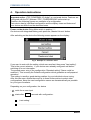
POWERMIX 6/3 digital
USER MANUAL
August 2011
POWERMIX 6/3 DIGITAL
This manual describes the hardware des „ITEC-POWER 6/3 digital“.
The user could found all operating instructions for the already installed and
configured device.
A technician finds the necessary data for the electrical connection of all inputs and
outputs as well as important safety-relevant references in this manual.
For start-up and configuring the equipment as well as to understand the function and
the various possibilities additionally the
ITEC POWERDESIGN manual
is essential. ITEC POWERDESIGN is a PC Software to configure and control the
„ITEC-POWER 6/3 digital“. The technician can easily configure the device as
requested and implement a wide variety of sound effects without using additional
devices.
You will always find the latest version of ITEC POWERDESIGN including the ITEC
POWERDESIGN manual for a free of charge download under:
http://itec-audio.com/download/powerdesign/powerdesignsetup.exe
1.1 ITEC-Tontechnik und Industrieelektronik GmbH
A-8200 LASSNITZTHAL 300 / AUSTRIA / EUROPE
www.itec-audio.com
[email protected]
2
www.itec-audio.com
POWERMIX 3/6 DIGITAL
POWERMIX 6/3 DIGITAL
Dear customer!
For over 20 years ITEC audio engineering stands for perfect sound quality and
simplest operation. ITEC amplifiers offer all necessary features to the technician to
ensure an optimum adjustment to the acoustic conditions. On the other hand they are
well understandably and simple to serve for the user.
High-end digital audio technology is usually reserved to professional recording and
broadcasting studios. With the new „ITEC POWERMIX 6/3 digital“ we are integrating
it into a mobile device, multiplying quality, performance and possibilities of
application. Simultaneously, handling is kept very simple and in fact layman-proof.
We can ensure you that you have made the right decision in acquiring the „ITEC
POWERMIX 6/3 digital“. You now own a product representing state-of-the-art
technology and usability with a functional design and a variety of features making
daily operation a delight.
We hope you will enjoy using your new device. Needless to say, we are happy to
take all your questions concerning audio engineering, lecturing technique, media
remote control, seminar room equipment, etc.
Your ITEC acoustic-team
3
www.itec-audio.com
POWERMIX 3/6 DIGITAL
POWERMIX 6/3 DIGITAL
Safety Instructions
Please read the operating instructions attentively before turning on the „ITECPOWERMIX 6/3 digital“.
You must use a grounded plug socket (PROTECTED PLUG) when charging or
operating the device!
Storing the device in humid conditions, operating it in pouring rain or near splashing
water could cause damage. Avoid exposing the device to temperatures above 50°C
or humidity above 95%.
Avoid temperatures below –10° when operating and temperatures below +5° when
storing devices with integrated battery packs (see also chapter 7).
Do not place other devices or objects on the housing of the "ITEC POWERMIX 6/3".
Do not try to open the device. No serviceable parts inside. In case of any damage or
problems always contact your dealer or the manufacturer.
The device can be connected to a PC via the serial interface for configuration
purposes. This should be done by trained sound engineers only.
Attention: Unplug an installed battery pack any time the device is opened by an
expert and then unplug the power supply.
Unplug the power cord before any maintenance or cleaning procedure.
The display should be cleaned gently using a dry cloth.
4
www.itec-audio.com
POWERMIX 3/6 DIGITAL
POWERMIX 6/3 DIGITAL
2. POWERMIX 6/3 digital: Front panel
Fig. 1 POWERMIX Front panel
1. Main switch: Used to turn On/Off the device
(additional devices connected to the “AC-OUT” connector are also turned on/off).
Devices with an integrated battery pack should be switched on/off by pressing the
Master volume button. Therefore the Main switch must be always turned on to
guarantee battery loading.
2. „Master-Volume“ Control: Used to control the volume of all input channels which
are configured as “controlled” inputs in „PowerDesign“.
Further functions:
- Hardware-Reset: Press the control button at least for 10 seconds.
- devices with integrated battery: Turn On/Off the device by press the control button
3. Display with touch screen, 3 snap in positions to warrantee legibility in each
possible installation location.
The following elements are arranged on the rear panel if you have a device labeled
with „i“
4. RS-232 Interface: Used to connect a PC via serial interface
(see ITEC POWERDESGN Manual)
5. RS-232 Interface Remote: for remote control.
(Attention: This isn’t a standardized RS232 connector, use only original accessories)
6. „LINE-IN“- connector: corresponds to input channel no. 6
Stereo-Cinch-connector (intern processed as mono channel !) to plug in external
audio devices e.g. CD-player, MP3-player etc.
7. „LINE-OUT“-connector: corresponds to output channel „OUTPUT 1“
Stereo-Cinch-connector (mono signal) to plug in recording devices.
5
www.itec-audio.com
POWERMIX 3/6 DIGITAL
POWERMIX 6/3 DIGITAL
3. POWERMIX 6/3 digital: Rear panel
Fig 2 POWERMIX Rear panel
1. Power supply AC-IN
Use the supplied power cord to plug into 230 VAC power.
Fuse: Glass tube fuse 5x20mm, 5A slow-blow.
2. AC-OUT
Switched power supply voltage to connect external devices as for instance PreAmplifiers, radio transmitters or any other devices with low power consumption.
Attention: Don’t connect power amplifiers via this connector.
3. Loudspeaker connector „SPEAKER OUT 1“
Used to connect low impedance or 100V Loudspeakers.
Maximal power consumption of connected 100 Volt Speakers: 75 Watt
Minimal resistance for low impedance speakers: 4 Ohm
6
www.itec-audio.com
POWERMIX 3/6 DIGITAL
POWERMIX 6/3 DIGITAL
4. XLR-output connectors
OUT2 - OUT3: balanced Line-outputs.
Pin assignment:
1……. ground
2.…....signal+
3........ signal –
Fig. 3 output connector
If you need to connect the balanced out to an unbalanced input (e.g. phone jack input), use
ground and signal+. Pin 3, don’t connect Signal-
5. XLR-input connectors
IN1 - IN2: balanced Microphone inputs, 12V Phantom power
IN3 - IN5: balanced inputs, optional Line/Mic.,
switchable 12V phantom power
Pin assignment:
1……. ground
2.…....signal+
3........ signal –
Fig. 4 input connector
If you need to connect an unbalanced input, use ground and signal+. Connect signal- with
ground !
6. Loudspeaker connector „SPEAKER OUT 2“ (optional)
This connector could be used if the optional component „ITEC POWER BOOST 2“
is installed. Pin assignment and features are equal to „SPEAKER OUT 1“ (see item
no. 3).
7. Antenna connector (optional)
This connector is available if the optional component „radio frequency receiver” is
installed!
BNC-jack to directly connect an antenna or a coaxial aerial line.
For each installed receiver there are 2 jacks installed.
Use the supplied antennas or order special ground-plane antennas with
corresponding cables.
Hint: If you use devices with a “i“-label, the “LINE-IN”, “LINE-OUT” and RS232
connectors are arranged on the rear panel (described in section 2).
7
www.itec-audio.com
POWERMIX 3/6 DIGITAL
POWERMIX 6/3 DIGITAL
4. Operation instructions
Important notice: „ITEC POWERMIX 6/3 digital“ is a universal device. Features are
configured with the PC Software “ITEC_POWERDESIGN” before start-up.
Therefore the following figures are examples of a configuration.
Each device has its individual configuration and the display views and features of
your device can differ from the described ones.
Power on the device: Bring Main switch in position “ I “.
On devices with integrated battery pack press the „Master-Volume“-button.
After switching on the device the following screen appears on the display:
Fig. 5 Example of a selection menu
If you want to work with the setting, which was used last, then press ”Last setting”.
That is the correct selection, if your device were already configured well before
switching off or an interruption.
The second menu entry is the configuration “Standard setting” (Name could be
modified ). This is mostly the Default configuration which guarantee a well prepared
operation.
This setting is usually a good starting position for your individual volume tuning.
After this two menu entries there are up to three further entries to select other
configurations. Keep the used configuration names as characteristically as possible
for your type of scenario.
Depending on your configuration, the device
-
waits for an user input
-
starts after
seconds with configuration:
„Last setting“
...........................................
8
www.itec-audio.com
POWERMIX 3/6 DIGITAL
POWERMIX 6/3 DIGITAL
4.1 Main view
Independent from your chosen configuration, the display shows a virtual mixer with
sliders for each input channel
Virtual volume
control
Battery state (only on devices with
integrated battery pack)
Name of the active configuration
Sound settings for inputs
Configuration selection
Gong (only if activated)
Lock/unlock touch screen
Fig. 6 Virtual Mixer (Example)
Number and labeling of visible sliders is individual configurable.
Following label names are defined for your device:
1.................. 2.................. 3.................. 4.................. 5.................. 6..................
4.2 Individual volume adjustment
The sliders on the display could be used for adjust the volume of the corresponding
input channels. There are the following possibilities to do this:
•
•
9
Move your finger on the slider button and drag this into the desired position.
(Dragging upwards increases the volume)
Tip with your finger above or underneath the slider button.
www.itec-audio.com
POWERMIX 3/6 DIGITAL
POWERMIX 6/3 DIGITAL
4.3 Master volume control
To control the volume for a defined group of inputs (e.g. all microphones), the
„Master-Volume“ control could be used.
This group depends on your individual device setting.
Following inputs of your device are controlled by the „Master-Volume“ Control:
..................
..................
..................
..................
..................
................
Turn the controller for volume adjustment
clockwise:
: turn up the sound
counterclockwise: turn down the sound
Fig. 7 Master volume control
Hint: Input channels which are muted by touch screen operation are displayed with
inverted naming labels. They are not affected by the master volume control. Only a
touch screen operation could release this input channel.
4.4 Start volumes
The start volumes for a specific configuration are predefined by programming a
specific configuration via PC software POWERDESIGN.
On the left side of each slider there is a little arrow which marks the start volume
setting. Thus the user can always see the start volume of the active configuration.
In some cases it could be necessary to modify this start volumes without a connected
PC. In the system menu of the device (see section 5.2) there is the entry “Save
Config” which allows to save the actual configuration permanent into the device.
Following approach is necessary to save the actual configuration settings:
- Choose the configuration to be modified (e.g. „Standard“).
- adjust the desired volume levels.
-
Press the “Menu” button and press the
symbol. Chose „System“ /
„Save Config“.
To avoid an unauthorized or unintentionally access you have to input a
security code.
The code for your device is:
After correct input of the security code you can hear a beep. The modified
configuration is successfully saved and your device will start with this settings.
10www.itec-audio.com
POWERMIX 3/6 DIGITAL
POWERMIX 6/3 DIGITAL
5. Additional Settings and Indicators
As mentioned, the „ITEC POWERMIX 6/3 digital“ device can be programmed and
configured in many ways using the software “Powerdesign” and a PC. Some
important parameters can also be modified directly at the device.
To enter the menu for additional settings, press the button labeled “Menu” and then
the button showing a gearwheel on the lower right of the display.
A sub-menu appears, offering the following menu items:
5.1 Audio
•
•
•
Line-In tone-controls
Input levels display
Output levels display
5.2 System
•
•
•
•
Display adjustments: Contrast and time before light dims automatically
Status of the rechargeable battery: Voltage and remaining capacity
Remote control: Selection of the remote control that is used
Save Config (see section 4.4)
5.3 Info
Displays device information and project relevant information.
11www.itec-audio.com
POWERMIX 3/6 DIGITAL
POWERMIX 6/3 DIGITAL
6. Connecting to External Devices
6.1 Playback
MC cassette decks, CD players, MP3 players etc, can be connected to the “Line-In”
sockets at the connection panel (see also the figure in chapter 6).
The volume adjustment is done via the fader labeled “LINE” on the display in mixer
mode.
For bass and treble adjustments, press the note symbol (lower left of the display) and
then tap on the modifier buttons.
The tone control only affects the Line input, all other inputs (like microphones) remain
unchanged as they are optimized at the factory. Changing sound settings on
microphone inputs is possible using the software “Powerdesign” and a PC.
6.2 Recording
Connect your recording device to the Line-Out socket at the front panel. All of the
inputs will be mixed according to the adjusted volume settings and sent to this output
socket.
On devices labeled with „ i “ this socket are on the rear panel.
6.3 Connecting PA-systems
Connect external P.A. systems using a standard XLR cable to the socket labeled “OUT 2” or
“OUT 3” (balanced line-level output).
The signals on this outputs depends on the configured routing and EQ settings.
This settings are defined during the installation of the device by the audio engineer.
12www.itec-audio.com
POWERMIX 3/6 DIGITAL
POWERMIX 6/3 DIGITAL
7. The rechargeable battery (optional)
If your device is equipped with a rechargeable battery enabling 6 hours of operation
independent from external power sources.
Charging the battery
The lectern must be turned off while charging. The rechargeable battery will not be
charged if the lectern is turned on.
Connect the power cord with the source socket. The built-in automatic chargingdevice ensures correct charging voltage. You can leave the device plugged,
overcharging is not possible.
Fully charged battery allows for an operation time of about 6 hours.
During charging, the display shows the charging current. If the battery is empty the
current will be around 2500mA. After some time, the current will go down to 100300mA depending on ambient temperature and age of the battery.
If the battery is fully charged the display will show “Battery is charged”.
Battery status and discharging protection
The battery status indicator is located at the lower right of the display. 4
marks indicate full capacity. 3, 2 and 1 marks indicate that 75, 50 and 25%
capacity remains.
The lectern will power down automatically if battery capacity is low in order to protect
the rechargeable battery from damage. A warning message will be displayed a few
minutes beforehand, suggesting to connect the lectern to external power.
Rechargeable Battery Maintenance
The rechargeable battery is sealed and maintenance free. In order to achieve a
long battery lifetime please follow some simple rules:
Charge the battery before the first and after each time the lectern is operated.
You may keep the lectern connected to the power line all year, the automatic
charging device will prevent overcharging.
Do not store the lectern with an uncharged battery!
Avoid temperatures below +5°C when storing the lectern!
13www.itec-audio.com
POWERMIX 3/6 DIGITAL
POWERMIX 6/3 DIGITAL
8. Wireless Microphones (optional accessory)
8.1 How to use
Turn on the wireless microphone.
Adjust the volume using the fader “WM-1” (WM-2, WM-3) on the display in mixer
mode.
Check if the microphone works everywhere where it will be used during the lecture or
presentation.
Be sure to check if the batteries are OK / charged.
Do not forget to switch off the microphone(s) when not in use. Battery lifetime is
limited to about 6 hours or less, depending on the microphone model supplied. When
using rechargeable batteries, this time may be even shorter.
If a wireless microphone is not in use, consider setting the fader „WM…“ to zero to
avoid possible RF distortions.
Notice:
Each lectern “Success” can be equipped with up to 3 wireless receivers for
the use with wireless microphones. Upgrades can be done easily.
Ask your dealer for further details.
14www.itec-audio.com
POWERMIX 3/6 DIGITAL
POWERMIX 6/3 DIGITAL
8.2 Exchanging Batteries
CAUTION: Batteries are hazardous waste. Old batteries have to be disposed of properly.
ITEC WM-716 - hand held microphone
(also WM 816 and WM 702)
Slide battery lid open, remove top battery and then pull the white
plastic strip to remove the other two batteries from the battery
compartment. Insert 3 new batteries!
Mind the poles (+ is at the bottom)!
Battery type: 3 pcs Mignon „AA“ 1.5 V
Batteries are okay: green LED is on
Batteries are low: red LED is on
ITEC WT-716 - button microphone
(also WT 816 and WT 702)
Open lid at the bottom of the casing and exchange all three batteries.
Mind the poles !
Battery type: 3 pcs Mignon „AA“ 1.5 V
Batteries are okay: red LED blinking
Batterie are low: red LED permanently on
ITEC WM-5100 - hand held microphone
Unscrew lid at the bottom end of the microphone and insert two new
batteries. Mind the poles (+ is at the bottom)!
Battery type: 2 pcs Mignon „AA“ 1.5V
Batteries are okay: red LED blinking
Batterie are low: red LED permanently on
The status of the battery is also shown on the LCD-display.
ITEC WT-5100 - button microphone
Open lid at the bottom of the casing and exchange both batteries.
Mind the poles!
Battery type: 2 pcs Mignon „AA“ 1.5V
Batteries are okay: red LED blinking
Batterie are low: red LED permanently on
The status of the battery is also shown on the LCD-display.
15www.itec-audio.com
POWERMIX 3/6 DIGITAL
POWERMIX 6/3 DIGITAL
Specifications
GENERAL
Power Supply
Maximum power consumption
Dimensions (without mounting brackets)
Dimensions with 19“ mounting brackets
Weight
Lacquer
INPUTS
Input 1-2 (XLR)
Input 3-5 (XLR)
Input 6 (Cinch)
OUTPUTS
Output 1 (Cinch)
Output 2-3 (XLR)
SPEAKER OUTPUT
Output power
Low impedance connector
Output transformer
INTERFACES
RS 232 PC
RS 232 Remote
SPECIAL AUDIO FEATURES
Four programmable configurations
Automatic microphone switcher/mixer
Flexible signal routing
VIRTUAL MIXER ON TOUCH SCREEN
Up to 6 Volume sliders
Bass and treble control
DSP (DIGITAL SIGNAL PROCESSING), PC PROGRAMMABLE
5 Input equalizer- 4-Band parametric
3 Output equalizer- 12-Band parametric
Compressor / Limiter
OPTIONS
Radio receiver (up to 2 units could be integrated)
Rechargeable battery (incl. Loading circuit)
2nd Power Amp. „ITEC Power-Boost 2“
110 – 230 V, 50/60 Hz
250 Watt
432 x 132 x 266 (WxHxD)
432 x 132 x 266 (WxHxD)
ca. 6,25 kg
silver (version “i“: black)
19”, 3 HE
Microphone input, Gain 10dB to 50dB
Phantom power 12 Volt
Line/Mic Input, Gain –20dB to 250dB
Phantom power 12 Volt, switchable
Line-Input Gain –20dB to 20dB
unbalanced Line-Out
balanced Line-Out
75 Watt RMS (2x75W optional)
Min. 4 Ohm
50/70/100 Volt, 75 Watt max.
Configuration via PC (PowerDesign)
Remote control interface
Diversity receiver UHF or VHF
12 Volt 7,2 Ah, Operation time ca. 8h
75 Watt, 50/70/100 Volt bzw. 4 Ohm
ITEC Tontechnik und Industrieelektronik GesmbH,
A-8200 Lassnitzthal 300 / Austria / Europe
Tel.: +43 (0)3133 /3780-0, [email protected],
www.itec-audio.com
16www.itec-audio.com
POWERMIX 3/6 DIGITAL