1
MD-300 Electronic Timer User's Manual
©1995 FarmTek, Inc.
1000-D Hwy 78 North
Wylie, TX 75098
(972) 429-0947
(800) 755-6529
MD-300 User’s Manual
Page 1
Congratulations on your timer purchase! Your new timer should
provide years of trouble-free service. To maximize the performance
and life of your timer, please read this user's manually carefully
before using your timer. It is important to familiarize yourself with
the timer before attempting to use it at your first event.
INTRODUCTION
Your new timer comes in a protective carrying case. Inside
the case you'll find the following items:
• Timer Console ("MD-300 Electronic Timer")
• Infrared light source ("Transmitter")
• Infrared light detector ("Receiver")
• Camera tripods (2)
• 125 foot cable
• A/C power adapters (2)
The MD-300 Timer supports a wide variety of events. The
basic timer with the equipment listed above can support
speed events such as barrel racing and pole bending. It can
also be used to time show jumping events which use a single entry and exit point. With optional equipment, the MD300 Timer can support additional events including team
penning, cutting, calf and team roping, dash / sprint events
and more!
This manual provides instruction for operation of the MD300 Electronic Timer. Topics include operation of the Timer
Console, use of the electric eyes and using the setup capability of the timer to select the type of event to be timed. For
events which require the use of optional equipment, additional information is provided in the user's manual supplied
with the optional equipment.
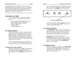
THE TIMER CONSOLE
The Timer Console is the heart of your new timer system.
The front of the Timer Console has four push-buttons for
controlling the timer and a time display. The back of the
Timer Console has five jacks for connecting power, the light
detector, an optional horn, an optional scoreboard display
and other accessories. These connections are discussed in
detail in later sections.
MD-300 User’s Manual
Page 1 (Cont’d)
The best way to learn about your new timer is to use it. Try
each of the operations outlined in the following sections as
you read through the manual.
Turning on the Timer Console
The Timer Console must be plugged into a standard wall
outlet to operate. Using either of the A/C power adapters
provided (they're identical), insert the small plug into the
POWER jack on the rear of the Timer Console and plug the
adapter into a wall outlet. As soon as the Timer Console is
plugged in, the Console is "on" and the time shown on the
display is zero. Now we're ready to push some buttons!
Manually Starting and Stopping the Timer
The START/STOP button is used to manually start and stop
the timer. When the timer is started, the time is first reset to
zero, and then the running time is shown on the display.
When the timer is stopped, the final time is shown on the
display.
When the Timer Console is not running, pressing the
START/STOP button starts the timer. If the timer is running,
pressing the button stops the timer. Even if the timer was
started by breaking the light beam, it can be stopped with
the START/STOP button, and vice-versa.
Resuming an Interrupted Timing
Whenever the timer is stopped via the START/STOP button or
by breaking the light beam, the final time is shown on the
display. However, the timer continues to count "inside."
Pressing the RESTART button, when the timer is stopped, resumes timing on the display. Since time was kept internally
while the display was "frozen," the time on the display now
reads as if the timer was never stopped. (Note: When using
the timer for jumping events, operation of the RESTART
button is slightly different than described here. See the
jumping event entries in the "Event Summary" table later in
this manual).
MD-300 User’s Manual
Page 2
Imagine the following: A rider speeds through the light
beam to start the timer. Unfortunately, her hat blows off
and falls through the light beam and stops the timer! Normally, the rest of her ride is wasted, but by pressing the RESTART button, her timing can be resumed as if the timer
were never stopped! Since you can resume timing via the
RESTART button, you no longer have to worry about false
triggers – you can even purposely stop the timer to measure
split times part way through a run.
Recalling the Previous Rider's Time
Have you ever missed recording a time because something
broke the beam and started the timer before you wrote down
the original time? Well, that's not a problem with the MD300 Timer. The PREVIOUS TIME button allows you to recall
the previous rider's time.
To view the previous rider's time, press the PREVIOUS TIME
button and hold the button down. The previous time is displayed as long as the button is held down. Release the button and the most recent time is restored. The previous time
can be checked even while the timer is running.
Locking Out the Electric Eyes
Some events, such as relays and jumping events, require
that riders pass through the beam multiple times before
passing through it one final time to stop the timer. For these
events, it is desirable to force the timer to ignore the electric
eyes until the rider passes through the final time.
To disable the electric eyes, press the RESTART button while
holding down the PREVIOUS TIME button (the PREVIOUS TIME
button is used like the SHIFT key on a typewriter). To remind the timer operator that the electric eyes have been
disabled, the message "Eye Off" is flashed occasionally over
the time. The electric eyes are re-enabled in the same manner – press the RESTART button while holding down the
PREVIOUS TIME button. The message "Eye On" is displayed
briefly while the buttons are pressed and then the flashing
"Eye Off" message is removed.
For team penning and cutting events, the electric eyes are
automatically disabled whenever the timer stops. This allows
MD-300 User’s Manual
Page 2 (Cont’d)
animals and personnel to cross through the electric eyes
while preparing for the next team without starting the timer.
While the eyes are disabled, the message "Eye Off" is flashed
on the display to remind you that the eyes are disabled. To
re-enable the eyes for the next team, press the RESTART
button while holding down the PREVIOUS TIME button as described previously.
Note: This automatic disabling of the electric eyes can be
turned on or off for each event type. Further, the eyes can be
set to automatically disable when the timer stops or when it
starts. This can be useful for show jumping events, for example. Call FarmTek for assistance.
Timer Setup
The MD-300 Timer has a powerful setup capability used to
configure the timer for the particular event to be timed.
Setup features are accessed by pressing the SETUP button
any time the timer is stopped. Pressing SETUP places the
timer into the setup "mode." Once in the setup mode, the
buttons on the timer perform the functions listed in blue to
the right of each key. The NEXT and PREV buttons move forward and backward through the list of available setup options. The SELECT OPTION button chooses the currently displayed setup option as the one you wish to perform. The
EXIT SETUP button exits the setup mode and returns to normal timing operation.
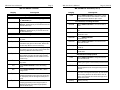
The list of setup options available is shown in the "MD-300
Setup Options" table following. The options are listed in the
order they appear on the Timer Console. The first column
shows the Timer Console display for each setup option. The
second column gives a brief description of the setup option.
When the last setup option is displayed, pressing the NEXT
button wraps around to the first setup option in the list.
Similarly, when the first setup option is displayed, pressing
the PREV button wraps back to the last setup option in the
list. As you scroll through the list of setup options, the
timer beeps any time the current event type, time format or
counting direction is displayed. This allows you to identify
the event type, time format and counting direction currently
in use.
MD-300 User’s Manual
Page 3
MD-300 User’s Manual
MD-300 SETUP OPTIONS
Display
Description
Electric Eye Alignment Status
Good / Bad
Good A / Bad A
MD-300 SETUP OPTIONS (cont'd)
Display
Dash
Alignment status of the electric eye plugged into
the RECEIVER jack.
Alignment status of electric eye plugged into the
AUX jack. Displayed only for events which use the
second electric eye.
Good H / Bad H Alignment status of electric eye plugged into the
HORN jack. Displayed only for events which use
the third electric eye.
Page 3 (Cont’d)
Description
Press SELECT OPTION to select dash or sprint
events which measure time between a start line
pair of eyes and a finish line pair of eyes.
Time Formats, Counting Direction
999.999
Press SELECT OPTION to count in seconds to
.001
9999.99
Press SELECT OPTION to count in seconds to
.01
9.59.999
Press SELECT OPTION to count in minutes and
seconds to .001
Event Types
Barrel
Press SELECT OPTION to select the Barrel Racing event.
99:59.99
Press SELECT OPTION to count in minutes and
seconds to .01
Rope 1
Press SELECT OPTION to select Roping using
one electric eye (eye for calf or steer, RP-210 Automatic Rope Barrier used on rider's box).
99:59:59
Press SELECT OPTION to count in hours, minutes and seconds.
Rope 2
Rope 3
Press SELECT OPTION to select Roping using
two electric eyes (eye for calf or steer and RP-250
Electric Eye Barrier across rider's box).
Press SELECT OPTION to select Roping using
three electric eyes (eye for calf or steer and RP250 Electric Eye Barrier across header's box and
heeler's box).
Cnt Up
Press SELECT OPTION to force the timer to
count up.
Cnt Dn
Press SELECT OPTION to force the timer to
count down.
Miscellaneous Setup Options
Horn
Press SELECT OPTION to change the time the
horn should sound.
Pen
Press SELECT OPTION to select the Team Penning event.
Horn 2
Press SELECT OPTION to change the time that a
warning horn (prior to the final horn) should sound.
Cut
Press SELECT OPTION to select the Cutting
event.
SB Brt
Bull
Press SELECT OPTION to select Bull or Bronc
riding events.
Press SELECT OPTION to select the next scoreboard brightness level. Not supported by all scoreboards.
Set.Def
Press SELECT OPTION to set default values. The
horn time, warning horn time (Horn 2), time format
and counting direction are saved as the new values to use whenever the current event type is selected in the future
Factory
Factory use only.
Eqst 1
Press SELECT OPTION to select the Show
Jumping (equestrian) event using one pair of electric eyes (entry and exit through the same pair of
eyes).
Eqst 2
Press SELECT OPTION to select the Show
Jumping (equestrian) event using two pairs of
electric eyes (entry and exit through separate
pairs of electric eyes).
MD-300 User’s Manual
Page 4
Timer Setup - Checking Electric Eye Alignment
To work properly, the infrared light source (Transmitter) and
infrared light detector (Receiver) must be properly aligned.
The procedure for aligning the electric eyes is discussed in
detail in the "Aligning the Electric Eyes" section.
Checking alignment of the electric eyes is a setup option
provided by the MD-300 Timer. To check alignment of the
electric eyes, press the SETUP button. The first item displayed is the alignment status of the electric eyes connected
to the RECEIVER jack. If the eyes are properly aligned, "Good"
is displayed. If not properly aligned, "Bad" is displayed. An
alignment status of "Good" not only indicates that the electric eyes are aligned, but also verifies that all connections
between the electric eyes and the Timer Console are good.
Once the alignment of the electric eyes has been checked,
press the EXIT SETUP button to return to normal timing operation.
Note that if you break the beam while checking the alignment status, the display shows "Bad" while the beam is broken. After the beam is restored, the display returns to
"Good."
If the currently selected event type uses more than one
electric eye, the alignment status of each additional electric
eye can be displayed by using the NEXT and PREV keys to
move forward and backward through the list of electric eyes
(see the "MD-300 Setup Options Table"). More information
regarding alignment of additional electric eyes is provided in
the user's manuals which come with the OE-205 Electric
Eye Package and the RP-250 Electric Eye Barrier.
Timer Setup - Selecting Event Type
One of the most important features of the MD-300 Timer is
its ability to support a wide variety of events. The event
types present in the MD-300 Timer are listed in the "MD300 Setup Options" table and summarized in the "Event
Summary" table. Even though a particular event may not be
listed in these tables, it is most likely supported by one of
the event types that is present. For example, though pole
bending is not specifically listed as an MD-300 event type,
pole bending has the same basic timing requirements as
MD-300 User’s Manual
Page 4 (Cont’d)
barrel racing. Likewise, bull dogging and goat tying have
similar timing requirements as roping events.
When the MD-300 Timer is first turned on, the "Barrel"
event type is automatically selected. (Note: You can change
the event type selected at power-on to be any of the other
event types as well. Contact FarmTek for assistance.) If you
requested factory setup of a power-on event type other than
"Barrel," it is shown here:
To change the current event type, press the SETUP key to enter the setup mode. As shown in the "MD-300 Setup Options
Table," ten of the setup options available are event types
that may be selected. Use the NEXT and PREV keys to scroll
forward and backward through the list of events until the
desired event type is displayed. Then press the SELECT OPTION button to select the displayed event type. "Done" is displayed for a moment to indicate that your request has been
performed. The timer then returns to the timing mode with
the time reset to zero.
Note that the new event type is selected only when SELECT
OPTION is pressed. You may exit setup without changing the
event type by pressing EXIT SETUP. Also note that whenever
the currently active event type is displayed, the timer beeps.
This allows you to determine the event type currently in use.
Whenever a new event type is selected, the MD-300 Timer
automatically sets the time format, counting direction,
warning horn time and final horn time for that event. These
values can be different for each event type. Further, you
may change these defaults to any value you desire. Whenever the event type you modified is selected, your values for
time format, counting directions, etc., are automatically set.
See the "Timer Setup - Setting Default Parameters" section
for more information.
The following "Event Summary" table provides information
about each event supported by the MD-300. If optional
equipment is required to support an event, additional information is provided in the manual supplied with the optional equipment.
MD-300 User’s Manual
Page 5
"Barrel" - Barrel Racing, Pole Bending, etc.
Time Format: Counting up in seconds to .001
Warn. Horn: None
Final Horn:
None
Operation:
A single pair of electric eyes both starts and
stops the timer.
"Rope 1" - Roping, Bull Dogging, Goat Tying, etc.
Time Format: Counting up in seconds to .001
Warn. Horn: None
Final Horn:
None
Operation:
The MD-300 Electric Eyes form a start line
broken by the cattle to start the timer. When
the timer is started, a conventional rope barrier across the rider's box is released via the
RP-210 Automatic Rope Barrier. The electric
eyes do not stop the timer.
"Rope 2" - Roping, Bull Dogging, Goat Tying, etc.
Time Format: Counting up in seconds to .001
Warn. Horn: None
Final Horn:
None
Operation:
The MD-300 Electric Eyes form a start line
broken by the cattle to start the timer. A
second electric eye (RP-250 Electric Eye Barrier) is used across the rider's box. If the
rider breaks out before the cattle start the
timer, the OE-200 Automatic Horn is
sounded to flag the "broken barrier." The
electric eyes do not stop the timer.
"Rope 3" - Team Roping with Header and Heeler Barriers
Time Format: Counting up in seconds to .001
Warn. Horn: None
Final Horn:
None
Operation:
The MD-300 Electric Eyes form a start line
broken by the cattle to start the timer. A
second and third electric eye (RP-250 Electric Eye Barriers) are used across the header's and heeler's boxes. If either rider breaks
out before the cattle start the timer, the OE200 Automatic Horn is sounded to flag the
"broken barrier." The electric eyes do not
stop the timer.
MD-300 User’s Manual
Page 5 (Cont’d)
"Bull" - Bull and Bronc Riding
Time Format: Counting up in seconds to .001
Warn. Horn: None
Final Horn:
Eight (8) seconds
Operation:
The MD-300 Electric Eyes are fully disabled.
The timer is manually started when the bull
or bronc is released. When the time reaches
eight seconds, the horn sounds and the
timer automatically stops.
"Pen" - Team penning
Time Format: Counting up in seconds to .001
Warn. Horn: 60 seconds
Final Horn:
90 seconds
Operation:
The MD-300 Electric Eyes form an invisible
line broken by the lead rider to start the
timer. The timer continues to run when the
warning horn is sounded. The timer stops
when the final horn is sounded. The timer
may be manually stopped at any time. The
electric eyes do not stop the timer.
"Cut" - Cutting
Time Format:
Warn. Horn:
Final Horn:
Operation:
Counting down in minutes and seconds
none
Two minutes, 30 seconds (2:30)
The MD-300 Electric Eyes form an invisible
line broken by the lead rider to start the
timer. The timer stops when a time of zero is
reached and the final horn is sounded. The
timer may be manually stopped at any time.
The electric eyes do not stop the timer.
"Eqst 1" - Show Jumping (Equestrian)
Time Format: Counting up in seconds to .001
Warn. Horn: none
Final Horn:
none
Operation:
A single pair of electric eyes both starts and
stops the timer. Pressing RESTART after the
timer has been manually stopped resumes
timing from the time shown on the display,
rather than from the time kept internally
while the timer was stopped. If timer accidentally stopped by breaking the light beam,
RESTART operates normally.
MD-300 User’s Manual
Page 6
"Eqst 2" - Show Jumping (Equestrian)
Time Format: Counting up in seconds to .001
Warn. Horn: none
Final Horn:
none
Operation:
The timer is started with one pair of electric
eyes and stopped by a second pair of electric
eyes (OE-205 Electric Eye Package). Pressing
RESTART after the timer has been manually
stopped resumes timing from the time shown
on the display, rather than from the time
kept internally while the timer was stopped.
If timer accidentally stopped by breaking the
light beam, RESTART operates normally.
"Dash" - Dash and Sprint Events
Time Format: Counting up in seconds to .001
Warn. Horn: none
Final Horn:
none
Operation:
The timer is started with one pair of electric
eyes and stopped by a second pair of electric
eyes (OE-205 Electric Eye Package).
Timer Setup - Time Format and Counting Direction
The MD-300 Timer can count in several different time formats: Seconds to .001, seconds to .01, minutes and seconds to .001, minutes and seconds to .01, and hours minutes and seconds in whole seconds. In addition, the timer
can count up or count down.
When the timer is set to count down, the timer starts
counting from the final horn time specified for the event,
down towards zero. When zero is reached, the horn sounds
and the timer automatically stops. The time never decrements below zero. If RESTART is pressed to resume timing
after the displayed or internal time has reached zero, the
display will show zero time and the timer beeps twice to
alert you that time cannot be restarted. Similarly, if the final
horn time is set to zero, then the timer cannot start since
the start time is the same as the stop time (0).
Whenever a new event type is selected, the MD-300 Timer
automatically sets the time format and counting direction,
along with other parameters, for that event. Because of this,
it is unlikely that you will need to manually set the time
format or counting direction very often. However, if required,
MD-300 User’s Manual
Page 6 (Cont’d)
you can temporarily override the default settings for the current event type as outlined in this section. You can permanently record changes in time format and counting direction
for the current event using the "Set.Def" setup option. See
the "Timer Setup - Setting Event Defaults" section for more
information.
You should select a new time format or counting direction
after you have selected a new event type – if you are changing the event type at all. To change the time format or
counting direction, press the SETUP key to enter the setup
mode. As shown in the "MD-300 Setup Options Table," five
of the setup options available are time formats and two of
the options are used to specify "Count Up" or "Count Down."
Use the NEXT and PREV keys to scroll forward or backward
through the list of time formats until the desired time format is displayed. Then press the SELECT OPTION button to
select the new time format. "Done" is displayed for a moment to indicate that your request has been performed. The
display is then restored to show the time format you just
selected and the timer remains in setup mode. If desired,
you may continue to use the NEXT and PREV keys to select
other setup options. For example, you may scroll forward to
select a new counting direction. Selection of a new counting
direction is done in the same manner as selecting the time
format: When the desired counting direction is displayed,
press SELECT OPTION to select the new counting direction.
When you are finished making changes, press the EXIT
SETUP button to return to normal timing operation.
Note that a new time format or counting direction is selected
only when the SELECT OPTION button is pressed. You may
exit setup without changing the time format or counting direction by pressing EXIT SETUP before pressing the SELECT
OPTION button. Also note that whenever the currently active
time format or counting direction is displayed, the timer
beeps. This allows you to determine the time format and
counting direction currently in use.
MD-300 User’s Manual
Page 7
Timer Setup - Setting the Warning and Final Horn Times
The MD-300 Timer can be configured to automatically
sound a warning horn (after which the timer continues to
run), and a final horn, at which time the timer stops. The
timer forces the warning horn time to occur before the final
horn time. When either of the jumping event types is selected, ("Eqst 1" or "Eqst 2"), the timer continues to run even
after the final horn is sounded. Horns available for the MD300 Timer include the OE-200 Automatic Horn and scoreboards with built-in horns. More information is provided in
the manuals supplied with the OE-200 Automatic Horn and
the scoreboards.
Whenever a new event type is selected, the MD-300 Timer
automatically sets the warning horn time and final horn
time, along with other parameters, for that event. Because
of this, it is unlikely that you will need to manually set the
horn times very often. However, you can temporarily override the default settings for the current event type as outlined in this section. You can permanently record changes
in horn times for the current event using the "Set.Def" setup
option. See the "Timer Setup - Setting Event Defaults" section for more information.
You should set a horn time after you have selected a new
event type – if you are changing the event type at all. To
change either horn time, press the SETUP key to enter the
setup mode. As shown in the "MD-300 Setup Options Table," two of the setup options available are used to set the
horn times. "Horn" is used to set the final horn time and
"Horn 2" is used to set the warning horn time. Since the
warning horn time is forced to be less than the final horn
time, you should set the final horn time before setting the
warning horn time. The horn time options are near the end
of the setup options list – you may find it quicker to use the
PREV key to go backwards from the end of the list to reach
the "Horn" or "Horn 2" option rather than scrolling forward
through all the event types and time format options. To
change a horn time, press the SELECT OPTION button when
the desired "Horn" or "Horn 2" option is displayed. As soon
as the button is pressed, the current horn time setting is
displayed.
A horn time setting of zero means the horn will not sound.
Otherwise, the time displayed is the elapsed time after
which the horn will sound. When counting up, the horn
MD-300 User’s Manual
Page 7 (Cont’d)
time shown is simply the time at which the horn will sound.
However, when counting down, it is a little more complicated. For example, assume the final horn time is set to 90
seconds. When the timer is started, timing starts at 90 seconds and counts down towards zero. When zero time is
reached, the horn sounds and the timer stops. The horn
sounds after 90 seconds have elapsed – not when the display reads 90 seconds. Similarly, a warning horn time of 60
seconds – when counting down – implies that the warning
horn will sound after 60 seconds have elapsed. In this example, 60 seconds have elapsed when the displayed time
has counted down to 30 seconds.
When a horn time is displayed, press the NEXT key to increment the horn time value. Press the PREV key to decrement the horn time value. For horn times less than 30 seconds, the time increments and decrements one second at a
time. Above 30 seconds, the time increments and decrements in 15 second intervals. When changing the warning
horn time, the warning horn time is forced to be less than
the final horn time. The timer beeps twice if you attempt to
set the warning horn time above the final horn time. Further, if the final horn time is set lower than the warning
horn time, the warning horn time is forced to zero (off).
After the desired horn time value has been set, press the
SELECT OPTION button to "select" the new horn time. "Done"
is displayed for a moment to indicate that your request has
been performed. The display then restores the horn option
you selected and the timer remains in setup mode. If desired, you may continue to use the NEXT and PREV keys to
select other setup options (setting the warning horn time,
for example). When you are finished making changes, press
the EXIT SETUP button to return to normal timing operation.
Note that a new horn time is set only when the SELECT OPTION button is pressed after changing a horn time. You may
exit setup without changing the horn time by pressing EXIT
SETUP before pressing SELECT OPTION to set the new horn
time.
Timer Setup - Setting Event Defaults
As covered previously, whenever a new event type is selected, the MD-300 Timer automatically sets the time format, counting direction, warning horn time and final horn
MD-300 User’s Manual
Page 8
time for that event. The factory default values for these parameters for each event are shown in the "Event Summary"
table. If desired, you may alter these automatically selected
parameters so that your own values are set whenever a new
mode is selected.
First, configure the timer as you require by selecting the
event type, time format, counting direction, warning horn
time and final horn time as outlined in the preceding sections. Then, use the NEXT or PREV key to move through the
list of setup options until "Set.Def" (set defaults) is displayed. Press the SELECT OPTION button to record the current settings as the new default values for the current event
type. "Done" is displayed for a moment to indicate that your
request has been performed. The display is then returned to
the "Set.Def" option and the timer remains in setup mode. If
desired, you may continue to use the NEXT and PREV keys to
select other setup options. When you are finished, press the
EXIT SETUP button to return to normal timing operation.
Now, whenever the event type you just modified is selected,
your new parameters for time format, counting direction,
etc., will be used.
Note that the new parameters are permanently recorded
only if the SELECT OPTION button is pressed while the
"Set.Def" option is displayed. You may exit setup without
permanently recording your changes by pressing EXIT SETUP
before selecting the "Set.Def" option. If required, it is possible to restore the original factory settings. Call FarmTek for
assistance.
Timer Setup - Setting Scoreboard Brightness
Some scoreboards support different brightness levels which
can be controlled from the MD-300 Timer Console. By default, the brightness level is set to maximum brightness
whenever the timer is turned on. You can change this default condition. Contact FarmTek for assistance.
To change the scoreboard brightness level, press the SETUP
key to enter the setup mode. As shown in the "MD-300
Setup Options Table," the "SB Brt" setup option is used to
change scoreboard brightness. Since the brightness option
is near the end of the setup options list, you may find it
quicker to use the PREV key to go backwards from the end of
the list to reach the brightness option rather than scrolling
forward through all the other setup options. Once the "SB
MD-300 User’s Manual
Page 8 (Cont’d)
Brt" option is displayed, pressing the SELECT OPTION button
causes the scoreboard to alternate between the dim and
bright brightness settings. Note that not all scoreboards
support brightness control. When you are finished making
changes, press the EXIT SETUP button to return to normal
timing operation.
Alternate Button Functions
In addition to the normal functions of timer start/stop, restart, etc., the buttons on the MD-300 Timer Console perform an alternate function when pressed while holding down
the PREVIOUS TIME button. Here's how:
1) Press and hold down the PREVIOUS TIME button
(like the shift key on a typewriter), then...
2) Press any other key to perform the desired function.
ELEC. EYE
ON / OFF
RESET
TO ZERO
SOUND
HORN
RESET TO ZERO is not normally required – the timer automatically resets to zero whenever it is started. However, if
needed, this button allows you to force the display to read
zero (e.g., to force a scoreboard to show zero or blank).
ELEC. EYE ON/OFF enables and disables the electric eyes. See
the "Locking Out the Electric Eyes" section.
SOUND HORN provides the timer operator with manual con-
trol of the horn. More information is provided in the User's
Manual provided with the OE-200 Automatic Horn.
MD-300 User’s Manual
Page 9
THE ELECTRIC EYES
Page 9 (Cont’d)
Infrared Light Source - Transmitter
The infrared light source (Transmitter) outputs an invisible
light beam that is detected by the infrared light detector
(Receiver). When the light beam between them is broken, the
timer is either started, stopped or both based on the type of
event currently selected on the MD-300 Timer Console.
When the timer is started by breaking the light beam, the
time automatically resets to zero before starting in the same
manner as when the START/STOP button is pressed.
Whenever the beam is broken to start or stop the timer, the
Timer Console "beeps" to alert you about the event. This is
useful for detecting accidental interruptions of the beam.
When the same pair of electric eyes is used to both start and
stop the timer (e.g., barrel racing), the beam is ignored for
about two seconds after it is broken. This provides time for
dust to settle after the rider passes through the electric
eyes. Note: If you have need for a longer or shorter period
that the eyes are ignored, you can change this delay. Contact FarmTek for more information.
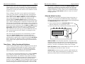
The Receiver is connected to the Timer Console via a 125
foot cable. This cable is used to signal the Timer Console
when the light beam is broken. The Transmitter needs no
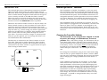
connection to the Timer Console. A typical arena set-up for
barrel racing is shown below:
Arena
The Transmitter is labeled "Transmitter" on its rear panel.
The Transmitter outputs the infrared light beam that is detected by the Receiver. The infrared light is emitted through
the solid black front panel. The Transmitter has built in rechargeable batteries to allow operation in the arena without
A/C power. However, if by mistake the batteries were not
charged, the Transmitter can be operated by plugging it in.
The Transmitter must be switched on to operate. If an A/C
power adapter is plugged into the Transmitter, the unit runs
from A/C power. If an A/C adapter is not plugged in, the
unit runs from its internal batteries. When not in use, the
Transmitter must be switched off to prevent discharge of the
batteries.
Charging the Transmitter Batteries
The Transmitter is not charged when shipped. It should
be given a full charge, as outlined below, as soon as
possible. After a full battery charge, the Transmitter will operate about twelve hours. Typically, this is enough time to
use the Transmitter on several occasions before recharging
is necessary. In fact, it is actually better for the batteries to
be used for ten to twelve total hours before recharging,
rather than just a few hours – as if recharged after each
use.
To recharge the Transmitter, plug it into a wall outlet using
either of the A/C power adapters for about 14 hours. Make
sure the unit is off when recharging. Do not leave the Transmitter charging for a single period of more than about 14
hours.
Transmitter
Entry
Chute
Receiver
125'
Cable
MD-300 User’s Manual
Console in
Announcer's
Stand
If the condition of the battery is not known, or the Transmitter has not been used for over a month, you can maximize performance of the battery by fully discharging and
then fully charging the battery. This should be done a day or
two before your event. To discharge the battery, leave the
Transmitter on until the red battery light stops flashing.
Then turn the Transmitter off and give the unit a full 14
hour charge. Do not store the Transmitter while it is fully
discharged – it should be charged within a day or so after
begin discharged.
MD-300 User’s Manual
Page 10
If the batteries in the Transmitter are not used for long periods of time, they should be given a full charge every three
months or so. Note that even if you always run the Transmitter from electricity, but never charge it, the batteries should
still be given a full charge every three months and when you
first receive your timer.
Checking Rechargeable Battery Condition
A lamp on the rear panel of the Transmitter provides an indication of battery condition. The lamp is brightest when
viewed from straight-on (not above, below, or to the side).
This is important when trying to view the lamp in bright
sunlight. The following notes apply to use of the battery condition lamp:
• The Transmitter must be on to check battery condition.
• The most accurate indication of battery condition is
provided after the Transmitter has been on for at least
30 to 60 seconds.
• If the lamp is blinking steadily, the batteries are still operational. Irregular blinking indicates the battery is on
its last breath – assume the battery is dead.
• If the lamp is off, the batteries are dead and need recharging. The Transmitter will not operate unless
plugged in or recharged.
As with any battery, when the Transmitter is first turned on
after being off for a period, even discharged batteries may
temporarily exhibit a high enough voltage to indicate "good."
However, a discharged battery will quickly drain and indicate "dead." For this reason, leave the Transmitter on for at
least 30 to 60 seconds before checking battery condition.
Infrared Light Detector - Receiver
The Receiver is labeled "Receiver" on its rear panel. The Receiver detects the infrared light beam emitted by the Transmitter. The infrared light passes through the solid black
front panel.
The Receiver is connected to the Timer Console by the 125
foot cable provided. This cable provides a signal to the Timer
Console when the light beam is broken. In addition, this ca-
MD-300 User’s Manual
Page 10 (Cont’d)
ble provides power to the Receiver. The Receiver requires
neither A/C or batteries to operate. To connect the cable,
insert either end of the cable into the jack labeled CONSOLE
on the rear of the Receiver. Insert the other end of the cable
into the jack labeled RECEIVER on the rear of the Timer Console. When using a second pair of electric eyes (OE-205
Electric Eye Package) for jumping events, dashes, etc., the
electric eyes which stop the timer plug into the AUX jack.
More information about using two pairs of electric eyes is
provided in the user's manual supplied with the OE-205
Electric Eye Package.
Tripods
For use in the arena, the electric eyes should be mounted on
the tripods provided. As you read this section, try the adjustments mentioned to familiarize yourself with the tripods.
The tripod has latches on its legs to adjust them to the desired length. Open the latch to extend or shorten a leg, then
close the latch to lock the leg in place.
Near the top of the tripod where the three legs come together, a center tube (neck) can be raised or lowered to further adjust the height of the tripod. Loosen the collar latch
by turning it counter-clockwise, and then raise or lower the
neck as desired. After adjustment, tighten the collar latch by
turning it clockwise.
The very top of the tripod is called the "head". Two adjustments allow the head to turn left to right, and to tilt forward and backward. The long handle is used to adjust the
forward and backward tilt. Turn the handle counterclockwise to loosen, and then use the handle to adjust the
tilt. Turn the handle clockwise to tighten the head in the
new position. The knob at the very top of the neck can be
loosened to allow you to move the head left and right. Turn
the knob counter-clockwise to loosen, clockwise to tighten.
A 1/4 inch screw protrudes through the top of the head. To
mount the Receiver or Transmitter on the tripod, position
the hole on the bottom of either unit over this screw. Turn
the knob under the head counter-clockwise (when viewed
from the top) to tighten the screw into the Receiver or
Transmitter. Tighten the screw firmly, but do not overtighten. Turn the knob clockwise to loosen the screw and
MD-300 User’s Manual
Page 11
remove the Receiver or Transmitter. Align the unit on the
tripod such that the long tripod handle extends towards you
and the rear of the unit faces you.
Aligning the Electric Eyes
The infrared light from the Transmitter is emitted in a narrow beam. This beam must be aimed at the Receiver to ensure that the Receiver "sees" the light beam. The infrared
light is emitted and received through the solid black panel
on each unit – this is the front of the unit. Read the tripod
section to familiarize yourself with the tripods before attempting to set up and align the Transmitter and Receiver.
To set up the electric eyes in the arena, first attach the
Transmitter and Receiver to the tripods as detailed in the
tripod section. Then adjust the tripods to the desired height.
The eyes should be high enough so that the light beam is
broken by the horse's body (not the legs).
Next, place the eyes on opposite sides of the arena. The eyes
can be separated by up to 200 feet. Aim the Transmitter in
the general direction of the Receiver and vice-versa. Plug the
cord into the rear of the Receiver now so that you do not
have to touch the Receiver after final alignment is complete.
Carefully align the Transmitter. Left to right alignment can
be checked by looking down either line on the top of the
Transmitter. The line should point straight at the Receiver.
Up and down alignment of the Transmitter is checked by
looking down the crack on the side of the unit. Adjust the
tilt such that the Receiver is directly in line when looking
straight down the crack on the side of the Transmitter.
When tightening the tripod adjustments after the alignments are made, make sure the alignment is still good –
tightening the tripod knobs may move your previous adjustment.
With the MD-300, alignment of the Receiver is also important. Repeat the procedure described for the Transmitter
using the Receiver.
To check the alignment, follow the procedures outlined previously to turn on the Transmitter and to connect the cord
from Receiver to the Timer Console. Then turn on the Timer
Console and press the SETUP key. The first setup option dis-
MD-300 User’s Manual
Page 11 (Cont’d)
played is the alignment status of the electric eyes. If the
eyes are properly aligned, "Good" is displayed. If not properly aligned, "bAd" is displayed. See the "Timer Setup Checking Electric Eye Alignment" section for more information.
Even though the Timer Console may show "Good", if you have
not carefully aligned the eyes as outlined above, you may
have a weak alignment that is sensitive to battery condition,
dust, or sunlight. Always carefully align the electric eyes before use as outlined above.
Alignment Hints
With a little practice, you'll be able to set-up and align the
electric eyes in minutes. Below are some suggestions in the
event you cannot obtain alignment or the alignment is sensitive to dust or sunlight.
• Make sure the cable plugs are fully inserted into the
Receiver and the Timer Console – push them in completely, a fraction of an inch can make a difference.
• Move the eyes closer together and re-align.
• Distance is reduced when the sun shines on the face of
the Receiver. If possible, switch sides with the Transmitter to keep the sun from entering the Receiver. If not
possible to switch sides, construct a simple shade for
the Receiver.
• Check the condition of the Transmitter batteries as outlined in the "Checking Rechargeable Battery Condition"
section. If the batteries are dead, use an A/C adapter to
plug the Transmitter into an A/C outlet to operate. As
mentioned previously, if the batteries are severely discharged, it may take several minutes before the Transmitter operates properly even after the A/C adapter is
plugged in. The quickest way to restore operation to a
severely discharged Transmitter is to plug it in with the
switch turned off for one or two minutes and then turn
the switch on (leaving the A/C adapter plugged in) to
operate the Transmitter.
MD-300 User’s Manual
Page 12
Simultaneous Operation of Two MD-300 Timers
If your event requires simultaneous operation of two complete timers (both timers start and stop at the same time
and provide backup for each other), the MD-300 Electronic
Timer can provide this capability. However, if two light
sources (Transmitters) are on at the same time, and pointing
in the same direction, they may interfere with each other at
the light detector unit (Receiver) and prevent proper operation. The following options are available to ensure proper
operation:
1) Set up both timers, but turn on just one of the two
Transmitters. Both Receivers will "see" the beam, but
since the beam is coming from only one Transmitter,
there is no interference. This provides fully redundant
timing. This also allows you to switch to the second
Transmitter after 10-12 hours of battery operation
have expired on the first Transmitter, and run for another 10-12 hours on battery.
2) Set up both timers, but have the pairs of eyes pointed
in opposite directions. I.e., each side of the arena will
have a Transmitter and a Receiver. With this configuration, both Transmitters can be on at the same time.
CARE OF YOUR TIMER
Your new timer has been designed to withstand a rough environment and treatment. However, a little extra effort to
take care of your timer and keep it clean will greatly extend
its life and reduce the chance of failure. The carrying case is
the "heart" of your timer care routine. Always store and
carry your timer in this case.
The Transmitter and Receiver units have been designed to
withstand a little rain. However, they are not waterproof. Do
no leave them uncovered during a heavy thunderstorm. If
they get very wet, allow them to dry out before using them
again.
MD-300 User’s Manual
Page 12 (Cont’d)