1
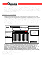
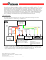
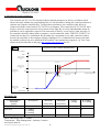
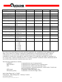
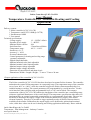
Peltier Controller QC-PC-CO-CH1
User Manual
Temperature Controller for Automatic Heating and Cooling
Applications
Delivery content:
1 Peltier controller QC-PC-CO-CH1
1 Temperature sensor NTC 10KΩ (β=3977K)
1 Potentiometer 10KΩ
1 User manual
Technical specifications:
-Voltage supply:
12….24VDC/<45mA
-Separate driver supply:
3…48VDC
-Maximal Peltier current:
20A
-Serial Interface:
3,5mm Stereo-Klinke
-Temperature range:
-40°C - +100°C
-Sensitivity: 0,1 °C
-Accuracy +/- 0,2 K
-P-control characteristic
-Control parameter for heating and cooling range
separately adjustable
-Digital Output definable
-Maximal nominal value limit adjustable
-Minimal nominal value limit adjustable
-Maximal output voltage adjustable
-Minimal output voltage adjustable
-Detection of sensorial burst and short circuit
-Dimensions: Width x Length x Height – 71 mm x 75 mm x 24 mm
1 Proper application of the controller QC-PC-CO-CH1
The Peltier controller QC-PC-CO-CH1 has been developed to actuate Peltier elements. The controller
undertakes the control of the temperature in a tempering setup. The temperature range of the controller
serves from -40°C to +100°C, while the controller triggers the Peltier element automatically for a
suitable heating or cooling. The control parameters are programmable by a serial interface. Via this
serial interface either a display with programmable keys or a PC can be linked. The compact
construction of the QC-PC-CO-CH1 enables the integration of the controller into a controlling setup,
without a significant disturbance of the overall design. The temperature specification either has to be
implemented by an external connectable potentiometer or a programmable fixed value. The user has
the ability to determine the supply voltage of the controller and the driver supply of the Peltier
element separately. Thereby it is possible to trigger optimally nearby all Peltier elements that are
available on the market. Furthermore the output supply can be dedicated a minimal and maximal
value, while these values can be set for heating and cooling applications differently. Hence with the
Quick-Ohm Küpper & Co. GmbH
Components – Heat Management – Industry Ceramics
www.quick-ohm.de
20140505User Manual English Controller QC-PC-CO-CH1.doc
-1-
properties of the Peltier elements is taken into account, that the generable heating power is a multiple
of the cooling power. The compact controller QC-PC-CO-CH1 is delivered with preconfigured
parameters, which allows an immediate installation into the control without any programming. Please
read the user manual thoroughly. If you follow the advice and descriptions, a Peltier controller will
stand by your side, which diverse deployability, compactness and enormous performance capability is
unreached by any other controller.
2 The principle of the Peltier tempering:
The directed current flow through a Peltier element causes plenty of physical processes, which
recognizable effect is the spatial displacement of heat energy. The temperature on one side decreases
while the temperature on the opposite side increases. This allows the planar attachment of a solid
component to heat it up or cool it down purposefully. Compared to conventional gas compressors (e.g.
refrigerators) the Peltier element has many advantages. E.g. a noiseless tempering without any
hazardous materials, without any movable components and freedom from maintenance is possible.
Additionally these devices can be miniaturized in a way that would be unimaginable without the
Peltier element. Fig. 2 shows the setup of such a tempering application that should basically always be
constructed like that.
Fig. 2:
Temperature sensor
F
tempered area
Thermal grease
or
thermal foil
etc.
Peltier element
(printed side
above,
respectively
Red-Right)
heatsink
Here the basic composition, which is indispensable for the work with Peltier elements, is
recognizable. There is an area that should be brought to a certain temperature. This area is
equipped with a temperature sensor. On the other side the area is located where the heat gets
extracted from or the redundant heat energy is led to in case of a heating and cooling
application, respectively. In this second area the temperature is usually not surveilled. To
prevent a collapse of the application induced by an excessive removal or feeding of heat, this
area is contacted with the environment intensively. That implies that by the usage of a heatsink
Quick-Ohm Küpper & Co. GmbH
Components – Heat Management – Industry Ceramics
www.quick-ohm.de
20140505User Manual English Controller QC-PC-CO-CH1.doc
-2-
the surface gets enlarged multiply to establish the needed contact with the ambience. The size of
this heatsink and the impeccable bonding between Peltier element and heatsink on the one side
and between Peltier element and heating and cooling plate, respectively, on the other are the
basic conditions for the determination of the performance of their setup. If you always focus on
that basic structure, your results will be successful. Please visit the category Know how in the
section of the heat management on our website indicated below to deepen your knowledge.
Here you find tips and information in a comprehensible and visualized layout.
3. The electrical setup:
The wiring of the single components with the controller requires basic knowledge of electrical
engineering and has to be conducted by a qualified person.
Fig. 3:
Controller
QC-PC-C01C
Black
GND
Red
Yellow
12..24V
Blue
Orange
U-PE
3…48
VDC
-
+
Supply
voltage
12V … 24V
+PE
Grey
Brown
-PE
White
White
+2,5V
Green
Control
Gnd Poti Poti-Signal
+2,5V
Sensor
signal
Peltier element
Temperature sensor
NTC 10KΩ
β = 3977K
Supply voltage Peltier element:
Option1 (one power supply):
Option2 (two power supplies):
Potentiometer 10KΩ
Jumper to red
Jump minus of both power
supplies and lay orange on
plus
To run the controller, a source of direct current voltage is necessary. Sources in the range of 12VDC
to 24VDC are usable. The controller has a separate power input for the supply of the Peltier element
available. The zero potential of both voltage sources is merged on the black wire. Thus, the control
supply and the Peltier supply can either be separated or alternatively connected.
Quick-Ohm Küpper & Co. GmbH
Components – Heat Management – Industry Ceramics
www.quick-ohm.de
20140505User Manual English Controller QC-PC-CO-CH1.doc
-3-
4. Adjusting the control parameter:
The controller QC-PC-CO-CH1 already holds the default parameters in delivery condition which
allows the usage without any programming. But it is also possible to change the control parameters to
optimize the response characteristics. To adjust these parameters, the controller either has to be
connected with the control unit QC-PC-D-CH1 or a computer. The control unit QC-PC-D-CH1 has a
display, where the control process can be traced at first sight. By an easily understandable menu all
parameters can be adjusted as required. The connection is done by a wire and a 3.5mm jack plug. If
the controller should be linked with a computer, a serial connection with a FTDI TTL-232R-5V-AJ
connection line has to be established. Do not under any circumstances use other connection cables,
because the controller or the computer might get damaged. For a communication among each other
the suitable software has to be installed on the machine. One appropriate program is e.g. Tera Term,
which can be downloaded on the page http://ttssh2.sourceforge.jp/ for free.
Fig. 4:
Depiction of the control characteristics
Heat voltage
100%
Heat parameter
maximum Heating
70%
Hysteresis
Heat parameter
minimum heating
20%
Heat parameter
minimum cooling
0%
0%
current temperature
Range cooling
Range heating
Temperature
nominal value
Heat parameter
maximum cooling
100%
-100%
Cool voltage
Parameter list
Communikation
command
[name]
SW_VERSION
STATUS
CONTROL_MODE
Description
Software version
0 = inaktive
1 = cooling
2 = heating
0 = extern
Minimum
Maximum
min[value]
max[value]
read only
read only
read only
read only
-
-
Quick-Ohm Küpper & Co. GmbH
Components – Heat Management – Industry Ceramics
www.quick-ohm.de
20140505User Manual English Controller QC-PC-CO-CH1.doc
-4-
Factory
setting
read only
read only
Extern
R: reading
W: writing
R
R
R/W
1 = fix (intern)
OUTPUT
Output voltage
percental
SENSOR_TEMP
Sensor temperature
TEMP_OFFSET
Temperature offset
SETPOINT
Nominal value
SETPOINT_FIXED
Nominal value at
Control mode = 1
SETPOINT_MIN
Min.-temperaturlimit
SETPOINT_MAX
Max.-temperaturelimit
HYSTERESIS
Hysteresis
BANDWIDTH_COOL Bandwith cooling
MIN_COOL_OUTP
Minimal cooling
voltage in %
MAX_COOL_OUTP
Maximal cooling
voltage in %
BANDWIDTH_HEAT Bandwidth heating
MIN_HEAT_OUTP
Minimal heating
voltage in %
MAX_HEAT_OUTP
Maximal heating
voltage in %
PWM_FREQ
PWM-frequency
0 = 1 kHz
1 = 5 kHz
2 = 10 kHz
3 = 15 kHz
4 = 20 kHz
5 = 25 kHz
0.0
100.0
read only
R
-40.0
-10.0
-40.0
-40.0
+100.0
+10.0
+100.0
+100.0
read only
+20.0
R
R/W
R
R/W
-40.0
+100.0
-40.0
R/W
-40.0
+100.0
+100.0
R/W
0.0
0.1
0.0
1.0
10.0
100.0
1.0
1.0
0.0
R/W
R/W
R/W
0.0
100.0
100.0
R/W
0.1
0.0
10.0
100.0
1.0
0.0
R/W
R/W
0.0
100.0
100.0
R/W
2
R/W
0.0
read only
Fig. 4 shows the control behaviour of the controller graphically. By a modification of the parameters the
shape of the control curve changes. During the communication via terminal programs and PC-linkage
commands have to be send to the controller. Reading and writing commands are distinguished. The
commands are listed in the command list. In the last column it is recognizable what kind of command is in
use. R represents a readout command while W is a writing command. Commands with the identification R/W
can be both read out from the controller and written into it.
The following commands are defined:
CONNECT
Command for the start of communication
DISCONNECT
Command for the termination of the communication
GET
Command for the readout of the following values:
Current temperature; nominal temperature; control mode; Control state
and current output voltage in %
GET [name]
Command to readout the single values
SET [name] [value]
Command to overwrite the single values
Quick-Ohm Küpper & Co. GmbH
Components – Heat Management – Industry Ceramics
www.quick-ohm.de
20140505User Manual English Controller QC-PC-CO-CH1.doc
-5-
SAVE_ALL
FACTORY_DEFAULTS
Command to save all recently changed values non-volatile
Overwrites all parameters back to factory settings
[name] represents the communication command (cf. parameter list).
[value] represents the new parameter value.
Example:
Connect:
Input
CONNECT>Return<
Controller response
OK
The controller is connected with the computer. Only now it can be readout and written to. Before every
parameterization this command has to be sent to the controller principally.
Readout the current temperature:
Input
Controller response
The sensor measures currently 21.5°C
GET SENSOR_TEMP>Return<
21.5
Readout the current output voltage:
Input
GET OUTPUT>Return<
Controller response
100.0
The Peltier element is supplied with 100.0% of the driver voltage.
Multi reading:
Input
GET>Return<
Controller response
21.5 25.0 0 2 100.0
The sensor measures currently 21.5°C. The nominal temperature is 25.0°C. The nominal temperature is
preselected by an external potentiometer. Currently it is heated. The current voltage at the Peltier element
amounts to 100.0% of the driver voltage.
Control mode set fixed to 50°C:
Input
SET CONTROL_MODE 1>Return<
Controller response
OK
Input
SET SETPOINT_FIXED 50.0>Return<
Controller response
OK
The nominal value target of the temperature is set to 50°C internally.
Saving the parameter non-volatile:
Input
SAVE_ALL>Return<
Controller response
OK
The changed values are written into the controller non-volatile.
Remark: Without this command all changes get lost after the switchoff of the supply voltage. All parameters
will be restored that have been saved during the last non-volatile retention.
Reset all parameters back to the factory settings:
Input
FACTORY_DEFAULTS>Return<
Controller response
OK
Quick-Ohm Küpper & Co. GmbH
Components – Heat Management – Industry Ceramics
www.quick-ohm.de
20140505User Manual English Controller QC-PC-CO-CH1.doc
-6-
Now all parameters correspond to the factory settings again (cf. parameter settings).
Attention, this command overwrites the controller memory immediately, without the necessity to enter the
following command SAVE_ALL.
For a functional communication the following settings have to be performed in the software.
Baud rate:
Data bits:
Parity:
Stop bits:
Flow control:
Attention:
9600
8
none
1
none
After the switchoff of the supply voltage internal capacities can hold the voltage for five more
minutes. Please make sure that also after the switchoff of the supply voltage for that time the
circuit is not touched.
Approach PC-parametrization (TeraTerm):
1. Connect FTDI TTL-232R-5V-AJ and detect the COM-port with the device manager.
2. Start Tera Term
3. Select serial
4. Detect port like in point 1 and press OK.
5. Adjust under Settings>Terminal-settings: Transfer=CR/Submit=CR+LF and local echo.
Press OK
6. Input CONNECT>ENTER< should receive response OK
7. Commands can be entered now.
8. Quit programming with SAVE_ALL
Quick-Ohm Küpper & Co. GmbH
Components – Heat Management – Industry Ceramics
www.quick-ohm.de
20140505User Manual English Controller QC-PC-CO-CH1.doc
-7-