1
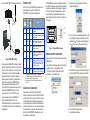
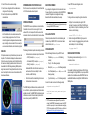
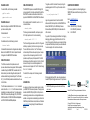
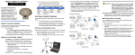
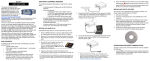
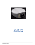
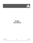
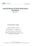
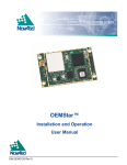
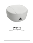
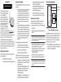
SMART-MR15TM
QUICK START GUIDE
AVAILABLE ACCESSORIES
The following SMART-MR15 interface cables can be ordered as
accessories:
•
This guide provides the information
you need to set up and begin using
your new SMART-MR15, a
combined L1+L2 GNSS receiver
and antenna, with Emulated Radar
(ER) output and NTRIP support. For
more detailed information about the
installation and operation of your
receiver, refer to the SMART-MR15
and OEMV® user manuals, which
can be found on the NovAtel Web site at www.novatel.com
through Support | Firmware/Software and Manuals.
•
To order a printed copy of the manuals, free of charge, follow the
instructions on the enclosed User Manuals postcard.
The SMART-MR15 supports Emulated Radar (ER) and
Bluetooth 2.0® functionality, and an integrated cellular modem
for receiving NTRIP corrections. The associated PC utilities and
USB drivers are included on the provided CD or available on the
Support page of our Web site.
SMART-MR15 BOX CONTENTS
In addition to this quick start guide, the following are provided
with your SMART-MR15:
•
1 - SMART-MR15 cellular activation guide
•
1 - User Manual postcard for requesting printed manuals
Evaluation cable (NovAtel part number 01018515) with
a 23-pin connector on one end and three DB-9
connectors and exposed tinned wires for power, ER,
ground, MKI, MODE, PPS and CAN, on the other. This
cable is designed to allow the rapid deployment and
evaluation of a SMART-MR15 on a construction or
agricultural vehicle. All signals are wired out in this
cable.
Streamlined cable (NovAtel part number 01018526) with
two DB-9 connectors, and exposed tinned wires for
power, ground and ER. This cable provides connection
for power, two serial ports, and emulated radar. It has
been designed for permanent installation. The cable
material is capable of withstanding a wide temperature
range and will not be damaged by exposure to
chemicals.
(USE with the 12023300 GSM mount only. DO NOT
USE with 12023301 CDMA Base).
•
•
GSM Antenna Base, NMO Magnetic Mount, 3.65 m
cable [NovAtel part number 12023300] (USE with
12023303 GSM/HSPA Antenna only)
Antenna Ground Plane Kit, for use on non-metallic
mounting surfaces [NovAtel part number 01018684]
Mounting Kit, Quick Release Plate (01018625)
•
Mounting Kit, Quick Release Assembly (01018578)
•
Mounting Kit, AG GPS 262 (01018623)
•
Mounting Kit, 5/8 Inch Adapter (01018624)
In addition to the above cable and mounting accessories, the
following accessories are available for the SMART-MR15:
•
CDMA Antenna, 2.2 / 4 dBi, 824-896 MHz / 1850-1990
MHz, NMO [NovAtel part number 12023296] (USE with
12023301 mount only)
•
CDMA Antenna Base, NMO Magnetic Mount, 30 cm
cable [NovAtel part number 12023301] (USE with
12023296 CDMA Antenna. DO NOT USE with
12023303 GSM Antenna)
•
GSM/HSPA Antenna, 3 / 4 dBi, 806-960 MHz / 17101990 MHz, NMO [NovAtel part number 12023303].
SMART-MR15 Enclosure
COM1
Before setting up your SMART-MR15, install NovAtel’s PC
Utilities on the Windows-based PC that you will use to
communicate with it. This PC must have an RS-232 DB-9 port.
DB9 Labeled COM1
AUX
DB9 Labeled AUX
COM2
Cellular
Module
COM3
Bluetooth
Module
INSTALLING THE PC UTILITIES
SMART-MR15
CPU
1. Start up the PC.
2. Insert the accompanying CD into the CD-ROM drive of the
computer.
If a CD is not included, please go to the Support page of our Web
site at www.novatel.com to access and download the most current
versions of our OEMV PC Utilities.
Four mounting kits are available for the SMART-MR15:
•
SETTING UP YOUR SMART-MR15
3. Select Install the OEMV PC Utilities from the window that is
automatically displayed. If the window does not
automatically open when the CD is inserted, select Run from
the Start menu and select the Browse button to locate
Setup.exe on the CD drive.
4. Install the PC Utilities by advancing through the steps
provided in the NovAtel GPS PC Utilities setup program.
Please go to the Support page of our Web site at www.novatel.com
to access and download the most current versions of our OEMV
PC Utilities.
Figure 1: SMART-MR15 System Diagram
The SMART-MR15 system architecture is shown in Figure 4. For
the basic setup, you will require a Windows-based PC with an
RS-232 DB-9 port and NovAtel utilities installed on it, and a
battery connection (+9 to +36 V DC). Complete the following
steps to connect and power your receiver.
1. Mount the SMART-MR15 on a secure, stable structure with
an unobstructed view of the sky. Mount the cellular antenna
at least 30 cm from the SMART-MR-15.
2. Connect the SMART-MR15 to a DB-9 serial port on the PC.
SMART-MR15 LEDS
LEDs on the front of the SMART-MR15 provide basic receiver
status information. The operation of the LEDs on the
SMART-MR15 is summarized in the following table:
TNC connector
Red
Cellular
Antenna
Tyco 23-pin
connector
Yellow
Green
Condition
The SMART-MR15 cable provides a means of receiving power
from a battery. The bare power wires (red for positive and black
for negative) are connected to a battery capable of supplying at
least 5 W. A 5 A fuse must be installed between the positive
terminal of the battery (or power distribution point) and the
positive supply lead of the cable to protect the wiring from short
circuit damage.
3. Select the New... in the Open dialog box. The Options |
Configuration dialog opens.
Refer to User Manual for
installation guidelines
Off
Off
Off
Power is not available or there has been a
hardware failure.
On
Off
Off
Power available but no satellites are being tracked.
No cellular connection.a
On
Flashing
Off
Tracking at least one satellite but not a valid
position. No cellular network connection.
On
On
Off
Position valid in basic autonomous mode. No
cellular network connection.
On
On
Flashing
SBAS tracking, but not enough data for enhanced
solution. Connected to cellular network but not
receiving RTK corrections.
On
On
On
Position valid in an enhanced accuracy modeb
(WAAS/EGNOS/MSAS/DGPS, OmniSTAR VBS/
XP/HP, or RTK). Connected to cellular network
and receiving RTK corrections.
COM1
User Supplied
5A Fuse
SMART-MR10: COM2
SMART-MR15: AUX
+
-
ER
Figure 2: SMART-MR15 Cabling
3. Provide power to the SMART-MR15, as follows: (a) Connect
the cable’s red wire (PWR+, connector pin 1) to the positive
side of a 12 or 24 V vehicular power circuit (or equivalent)
that is protected by a 5 A fuse. NovAtel recommends an
automotive blade-type fuse, rated for 5 A and with an
operating voltage of more than 36 V (recommended fuse
part numbers can be found in the SMART-MR15 user
manual). (b) Connect the cable’s black wire (PWR-,
connector pin 9) to the negative side of the power circuit. If a
NovAtel-supplied SMART-MR15 cable is not used, a
minimum wire size of 0.5 mm/ 20 AWG is required.
4. Connect the cellular antenna to the SMART-MR15.
5. Obtain a valid data SIM and insert into the unit
(GPRS/HSDPA model only) or activate the product with
Verizon (CDMA model only). Refer to the cellular activation
guide for details.
On
Flashing
Flashing
Fixed position with bad integrity. Connected to
cellular network but not receiving RTK corrections.
a. If the SMART-MR15 NTRIP client is not active, LED operation will not
reflect the status of the cellular network. Refer to the Installation chapter in
the SMART-10/15 User Manual for further information.
b. When acting as a reference receiver, all lights on solid indicates a good
fixed position.
4. Click
at the top of the configurations selection box to add
a new configuration. To delete a configuration, select it from
the list and click
. To duplicate an existing configuration,
click
. You can select any name in the list and edit it.
Figure 3: 23-pin and DB-9 Connectors
COMMUNICATING WITH THE SMART-MR15
To open a serial port to communicate with the receiver, complete
the following steps.
1. Launch CDU from the Start menu folder specified during the
installation process. The default location is Start |
All Programs | NovAtel PC Software | NovAtel CDU.
2. Select Open.... from the Device menu.
SMARTAG
5. Select Serial from the Type list and select the PC/laptop port
to which the SMART-MR15 is connected, from the Port list.
CONNECTING TO THE SMART-MR15
Cable connectors are illustrated in Figure 3. One DB-9
connector can be used to connect to a PC/laptop serial (RS-232)
communication port. The others can be connected to a modem
or radio transmitter to receive differential corrections (refer to
your user-supplied modem or radio transmitter information for its
connectors). In addition, there are a number of bare wires where
the outer insulation is cut away at the ends to expose tinned
wires. Refer to the SMART-MR10/15 User Manual for cable
pinouts. Cables are RoHS compliant.
6. Select 115200 from the Baud Rate list.
7. Cancel Hardware Handshaking.
8. Select OK to save the new device settings.
DETERMINING WHEN THE POSITION IS VALID
SAVECONFIG COMMAND
9. Select the new configuration from the Available device
configs area of the Open dialog.
When the receiver has a valid position, the Solution Status field
in CDU’s Position window shows Computed:
If you change the configuration of a function and want to save
the new settings for your next session, use the SAVECONFIG
command. This applies to most configuration changes,
Bluetooth and ER enable and disable, for example.
10. Select the Open button to open SMART-MR15
communications.
ENTERING COMMANDS
As CDU establishes the communication session with the
receiver, it displays a progress box. Once CDU is connected, the progress box disappears and several windows
open, including the Console window. CDU is now ready for
use to view status information, enter commands, or log data.
USING CDU
CDU provides access to key information about your receiver and
its position. The information is displayed in windows accessed
from the View menu. For example, select Position Window from
the View menu to display the position solution of the receiver. To
show details of the GNSS and geostationary (SBAS) satellites
being tracked, select the Tracking Status Window from the View
menu. Select Help from the main menu for more details on CDU,
its windows and features.
The SMART-MR15 uses a comprehensive command interface.
Commands can be sent to the receiver using the Console
window in CDU, which is opened from the View menu. Enter
commands in the text box at the bottom of the Console window.
When using NovAtel CDU, please close all graphical windows prior
to issuing the SAVECONFIG command.
CELLULAR ACTIVATION
Follow the procedure outlined in the cellular activation guide
included with your SMART-MR15. To check cellular modem
status information, enter log cellstatus.
The following information is important when entering commands:
•
Commands can be entered and output in three formats:
CONFIGURING NTRIP
Obtain the following information from your NTRIP caster:
•
IP address (caster_address in the following
example)
•
IP port (80 in the following example)
Abbreviated ASCII is the best format to use when you
want to work with the receiver directly. For data
collection, use ASCII or Binary.
•
Mount point (caster_mount in the following example)
•
User ID and password (userid and password in the
following example)
•
Click Enter to send the command string to the receiver.
•
Type of corrections (rtcmv3 in the following example)
•
Commands are not case sensitive.
•
ASCII (for example, log bestposa)
•
Abbreviated ASCII (for example, log bestpos)
•
Binary (for example, log bestposb).
The OEMV Family Quick Reference Guide, available on the CD
or on our Web site, provides comprehensive information about
available commands. The SMART-MR15 User Manual provides
information on a subset of these commands; in particular, the
ones commonly used by the SMART-MR15.
Connect to the caster as shown in the following example:
ntripcaster caster_address 80
ntripclient mount caster_mount userid password rtcmv3
NTRIP commands are save-configurable. After you save the
settings, the SMART-MR15 will automatically connect to the NTRIP
caster after a power cycle. For more information about configuring
NTRIP, refer to application note APN-057 found on our Web site at
http://www.novatel.com/support/knowledge-and-learning/.
To view NTRIP status and configuration, enter:
log ntripstatus
NMEA LOGS
To configure the receiver output through the command line:
1. Configure the communication port using the COM
command. For example, to set COM port 1to 9600 bps, no
parity, 8 data bits, 1 stop bit, no handshaking, echo off, and
break on, enter the following:
com com1 9600 n 8 1 n off on
2. Select and configure the NMEA string that you want to
output. For example, to log gpgga (position system fix data
and undulation) at 2 Hz, enter the following:
log gpgga ontime 0.5
ENABLING SBAS POSITIONING
This positioning mode is enabled using the SBASCONTROL
command, as follows:
sbascontrol enable auto
Once enabled, the Solution type field shown in CDU’s Position
window changes from Single to SBAS, and you may see SBAS
satellites in the Constellation window. SMART-MR15 will track
available SBAS satellites, including WAAS, EGNOS and other
SBAS systems.
ENABLING GL1DE®
EMULATED RADAR (ER)
To enable GL1DE, enter the following commands:
The SMART-MR15 outputs an emulated RADAR signal. The
enclosure outputs ER via the bare wire labeled ER on both the
SMART-MR15 evaluation and streamlined cables. Refer to
Appendix B.5 RADARCFG of the SMART-MR15 User Manual.
pdpfilter enable
pdpmode relative auto
ENABLING Bluetooth
Bluetooth is configured on the SMART-MR15 COM3 internal
port and is enabled by default.
To disable Bluetooth:
btcontrol disable
ER is enabled by default. To disable ER, use the RADARCFG
command as follows:
radarcfg disable
The following command enables ER, sets frequency step to
36.11 Hz/kph, update rate to 1 Hz and no smoothing:
radarcfg enable 36.11 1 1 2
To enable Bluetooth, enter the following command:
btcontrol enable
For detailed information about the configuration and enabling of
Bluetooth on the SMART-MR15, refer to Chapter 5 Bluetooth
Configuration in the SMART-MR15 User Manual.
USING THE CAN BUS
The CAN Bus is a serial bus that provides services for
processes, data and network management. CAN Bus capability
is available through the SMART-MR15 evaluation cable. CAN
Bus functionality is controlled through NovAtel’s optional API
software available through Customer Support. The API header
file (*.h) in the API folder provides documentation about the use
of the CAN Bus.
The CAN module is activated when a SETCANNAME command is
entered then after a SAVECONFIG, the CAN module is activated
immediately on all subsequent start-ups. The module supports
NMEA 2000 Parameter Group Message (PGN): PGN 129029
GNSSPositionData, PGN 129025 GNSSPositionRapidUpdate,
and PGN 129026 COGandSOGRapidUpdate.
The ER low and high pulse levels are within 0.5V of the ground
and battery, respectively. Note this is not a logic level output.
The rise and fall time is less than 1 ms. The ER outputs
reference battery GND when the output is logic low. It outputs
logic low until the vehicle speed is greater than 1 km/hr. It
provides an output frequency that represents 36.11 Hz/km/hr
(default value) with an effective range from 1 km/hr to 55 km/hr,
and uses 2D velocity for near-horizontal applications. The
default value can be changed to 26.11 or 28.12 Hz/km/hr using
the RADARCFG command.
To log data, use the LOG command. For example, to log the
pseudorange position to COM 1 every 30 seconds, enter the
following:
log com1 psrposb ontime 30
Logs can be generated in one of three formats: ASCII,
Abbreviated ASCII, or Binary. Refer to the SMART-MR15 User
Manual (OM-20000130) or the OEMV Family Firmware
Reference Manual (OM-20000094) for information about the
LOG command.
QUESTIONS OR COMMENTS
If you have any questions or comments regarding your
SMART-MR15 please contact NovAtel using one of these
methods:
Email: [email protected]
Web:
www.novatel.com
Phone: 1-800-NOVATEL (U.S. & Canada)
+1-403-295-4900 (International)
Fax:
+1-403-295-4901
If you prefer, CDU provides a graphical interface for configuring
data logging. Select Logging Control Window from the Tools
menu. In the Logging Control window, you can select which logs
to capture and choose the ports to which you want the data sent.
You can also specify a file in which to save the data.
To enable ER, for example, enter the following command:
radarcfg enable
When logging data through CDU, close all unused windows to
maximize COM port throughput and receiver CPU performance.
LOGGING DATA
An extensive set of logs has been created to capture the data
your SMART-MR15 receives and processes. These logs can be
directed to a SMART-MR15 port (COM1 or AUX) and can be
automatically generated when new or changed data becomes
available, or at regular intervals. Available logs are listed in the
OEMV Family Quick Reference Guide, found on our Web site at
www.novatel.com through Support | Firmware/Software and
Manuals.
SMART-MR15-specific logs are not included in the CDU dropdown menus.
Quick Start Guide
SMART-MR15
NovAtel, GL1DE and OEMV are registered trademarks of NovAtel Inc.
The Bluetooth® word mark and logos are registered trademarks owned by
Bluetooth SIG, Inc. and any use of such marks by NovAtel Inc. is under license.
Other trademarks and trade names are those of their respective owners.
© Copyright 2011 NovAtel Inc. All rights reserved.
Printed in Canada on recycled paper. Recyclable.
Unpublished rights reserved under international copyright laws.
GM-14915105
Rev 2
2011/03/02