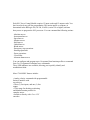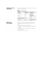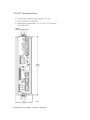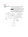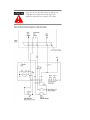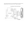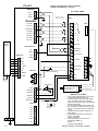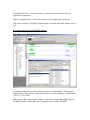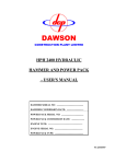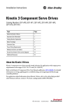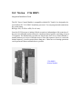
1
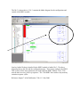
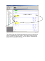
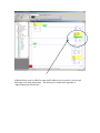
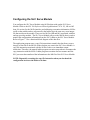
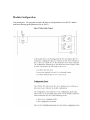
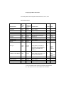
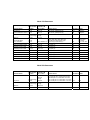
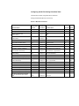
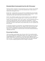
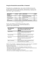
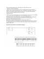
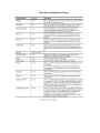
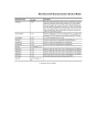
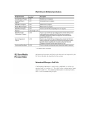
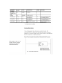
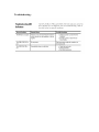
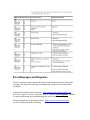
SLC Motion
1746 HSRV
Integration/Installation Guide
The SLC Servo Control Module is compatible with the SLC family. It is designed to be
used with an SLC 5/03 FRN 5.0 and later processor. You can program and commission
the system using
RSLogix 500, AI 500 or APS (5.0 or Later).
Once the SLC Processor is initiated, block execution is independent of the scan time of
the processor. Blended motion allows for complicated move profiles consisting of two to
32 segments. The blended move profiles are stored in the SLC Servo Control Module’s
internal memory as a series of absolute moves. Since the sequence of moves is stored in
internal memory, it can be executed more than once. Other move or homing operations
can be performed between blended move profiles.
1746-HSRV
Motion Module
Each SLC Servo Control Module requires 12 input words and 12 output words. You
don’t need to do any off-line programming. The motion profile or sequence is
determined in the RSLogix 500, AI 500, or APS (version 5.0 or higher) software
that you use to program the SLC processor. You can command the following actions:
· Absolute moves
· Incremental moves
· Speed moves
· Monitor moves
· Hold moves
· Unhold moves
· Blend moves
· Emergency stop operations
· Homing operations
· Preset operations
· Clear faults
· Alternate home moves
You can configure and program up to 16 separate blend motion profiles to command
from 2 to 32 segments of absolute move commands.
Three LED indicators are available, allowing you to quickly identify and
troubleshoot faults.
More 1746-HSRV features include:
• Analog velocity command with programmable
limits to interface with
servo drives
• Three (3) fast inputs, and one (1) fast
output
• 32 bit range for absolute positioning
and blended motion profiles for
complex moves
• Interfaces directly with +5 or +15V
encoders
1746-HT Termination Panel
Installation of the 1746-HSRV Hardware Configuration
Important
When wiring the multiple power sources for the HSRV be sure to follow the following
diagram for reference. Also reference the 1746-6.1.2 HSRV User Manual.
1746-HT
Sample wiring diagram for the 1746-HSRV
and the Ultra 3000 servo controller
Drive
ULTRA 3000
Drive
Dr Ret
SHLD
Interface cable:
2090-U3CC-D44xx
Encoder
CN1
CH A Hi
CH A Lo
A B SHLD
CH B Hi
CH B Lo
Z SHLD
CH Z Hi
CH Z Lo
17 CH A18 CH B+
19 CH B20 CH I+
21 CH I2
Power
Supply
Encoder Power
Ext Power
+5V
RET
+15V
+/- RET
-15V
+24
+24RET
EGND
CN2
16 CH A+
+5V
RET
+15V
SHLD
Common
25
Command +
26
Command -
27
I/O Common
28
29
I/O Power
30
Drive En
Drive Fault Reset
L1
L1
L2
L2
G
31
Drive Enable
32
Fault Reset
39
U
V
W
43
Relay +
44
Relay -
G
L1 L2
Estop
+24V
RES PB
RES PB
RESET
String In
String Out
Estop Reset
F, H, N, MP, Y series
motor with hi-res or
encoder option.
GND BAR
7-8-02
2090-UXNFBxx-Snn
IMPORTANT NOTES:
1.
Estop PB
O.T.
2.
Fast I/O
FI.1
+24V
FI.2
+24V
FI.3
RET
F0
2090-UXNPxxx-nnSnn
OPTIONAL O.T.
BYPASS
3.
4.
5.
6.
Notice velocity command signal to Ultra drive is
swapped to maintain proper phasing.
If motor direction is not correct, swap Velocity
cmd+ with Velocity Cmd -, also swap all of
channel A with channel B, then swap Channel B
Hi with Channel B Lo.
For better noise immunity wire the Motor and
Drive Thermals to a separate control relay (CR),
and wire the associated contacts into the Estop
circuit.
Set Digital Output Parameters in Ultrware to:
Relay: Ready
Set Digital Input Parameters in Ultraware to:
Input 1: Drive Enable
Input 2: Fault Reset
Set Encoder Parameters in Ultraware to:
Output Signal: Buffered
Divider: 1
Max Output Freq: 500kHz
Marker Gating: Gated with A and B
Setting Up Your SLC Servo Module
Before performing the procedures given in this chapter, follow the installation procedure
supplied with the drive that will be interfaced to the SLC Servo Module. This chapter
provides information to help you setup and configure the SLC processor and the SLC
Servo Module and includes the following topics: (refer to publication 1746-6.1.2 for
further information)
· Understanding the theory of motion control
· Powering up the SLC Servo Module
· Communicating between the SLC processor and the SLC Servo Module
· Entering encoder lines and computing counts
· Initializing DAC output voltage for drive symmetry
· Setting initial loop type
· Defining positive axis movement for the SLC Servo Module
· Coarse calibrating drive input scaling to SLC Servo Module DAC output voltage
· Fine calibrating of the DAC output voltage scaling
· Computing excess following error limit
· Selecting loop type
· Selecting axis acceleration rate
· Determining velocity and acceleration feedforward (for zero following error loop type
only)
· Setting axis and home specific parameters
· Understanding programming conventions
· Configuring your SLC processor
· Understanding your SLC Servo Module interface
· Configuring your SLC Servo Module
· Before programming your SLC Servo Module
· Downloading your configuration
· Understanding configuration errors
· Configuring the M0 file data tables
· Configuring the M0 file floating-point data tables
· Understanding configuration parameters
· Homing options
Understanding the Theory of Motion Control
The major components of a motion control system are:
· Machine mechanics
· Velocity loop
· Position loop
Machine Mechanics
Machine mechanics are the combined gearing, ball-screws, and
mechanical linkages that convert the motor’s rotary motion into the
axis motion that you want.
Velocity Loop
Velocity loop is a feedback control loop in which the controlled
parameter is encoder velocity. A tachometer is usually used for the
feedback device. Command input from the controller to the drive is a
DC voltage that is proportional to encoder speed (e.g., 1V equals 5
rpm and 5V equals 5000 rpm). Using the tachometer as feedback, a
drive maintains the speed of the encoder at the commanded speed
within its output capabilities.
A typical drive contains adjustments to do the following:
· Scale the input command voltage to the motor speed.
· Zero the motor speed for a zero input command.
· Set the maximum current (torque) to the motor.
· Control the response of the velocity loop.
Refer to the drive manual for instructions on setting these adjustments.
Position Loop
Position loop is a feedback control loop in which the controlled
parameter is mechanical position. The position loop compares
position feedback with the position command to modify the velocity
output signal to correct for any position error. Encoders are position
measuring devices that provide the SLC Servo Module with precise
actual axis position at all times. Based on motion statements, the SLC
Servo Module computes an axis position and compares it to the actual
axis position. Following error is the difference between the
commanded axis position and the actual axis position. Axis gain (or
position loop gain) sets the response on the position loop and scales
the following error to the velocity command output (drive input).
Your SLC Servo Module is a single-axis motion control that resides in a
1746 (SLC) rack. With a drive and servo motor, an SLC Servo Module
can control the position of one axis with encoder feedback. You can
place multiple SLC Servo Modules in one SLC Rack to control an entire
machine.
Powering Up the SLC Servo Module
The SLC Servo Module requires power from the SLC Rack backplane and the
termination panel for proper operation. You must power-up the SLC Rack with the SLC
Servo Module in the rack.
To power-up the SLC Servo Module:
1. Verify that your power supply connections for +5V DC,
±15V DC, and +24V DC are properly connected to the
termination panel.
2. Verify that your cable between the termination panel and the
SLC Servo Module is plugged in at both ends and the connectors
are securely in place.
3. Apply power to the termination panel and SLC Rack power at
the same time. The SLC Servo Module’s green RUN LED is lit
after a short delay for diagnostics.
4. If the SLC Servo Module’s RUN LED is:
Then:
ON - Module is OK – continue configuration
OFF - Go to step 1. (The SLC processor indicates a
slot fault at the SLC Servo Module location.)
Configuring the SLC Processor
The SLC processor must be configured to accept the SLC Servo Module as an I/O device.
Configure your processor by using the AI500, APS, or RSLogix 500 software running on
a personal computer.
Using RSLOGIX 500 – start a new project. Select the correct processor based on
application requirements.
Edit I/O configuration for rack (s) and necessary I/O per application requirement.
This is also when the 1746-HSRV motion module is selected and placed into the correct
slot.
Program example from 1746-HSRV sample.
An alternate method will use the sample program from Allen-Bradley. This program
contains many of the steps for setting up the module as found in chapter 7 of publication
1746-6.1.2 – July 2000.
HSRV Sample.RSS, This program contains some basic starting/testing ladder logic for
the HSRV module. Ladder files 3 & 5 contain this logic for the 1746-HSRV.
The file 3 is shown above. File 3 contains the ladder diagram for the configuration and
control of the HSRV module.
One key ladder file that is detailed for the HSRV module is ladder file 3. The above
diagram points to this file and the configuration rungs. These rungs configure the HSRV.
This is where all the setup parameters are loaded into the HSRV module. Note: This
must be done on every power-up sequence. The 1746-HSRV does not have any memory
retention on power cycles.
Reference chapter 7 of the Publication 1746-6.1.2 July 2000.
This example of ladder logic from the sample program shows discrete bits and also copy
module for sending data to the HSRV module. This bits and data words for the HSRV
may be found in the User Manual chapter 8. This is the Chapter on “Programming the
SLC Processor to run the SLC servo module”.
Additional logic may be added for status and feedback such as position, velocity and
following error status information. This data may be found in the appendix A.
“Input/Output Quick Reference”.
Communicating Between the SLC Processor and the
SLC Servo Module
Communication between the SLC processor and the SLC Servo Module occurs
asynchronously through 12 input and 12 output words. The SLC Servo Module requires
that an input is present from one to two coarse iterations before it is guaranteed to be
recognized. SLC Servo Module ladder logic rungs contain timers that can provide the
proper timing. The preferred method is to build handshake logic into the SLC Servo
Module ladder program. A handshake occurs when the SLC processor requests a change
and tests for an appropriate change in the SLC Servo Module status word before
continuing.
The SLC Servo Module can deny requests from the SLC processor because the SLC
Servo Module is not in the correct state to grant the request. Some SLC Servo Module
inputs are only recognized on the input transition. If the SLC Servo Module is not in the
correct state to grant a request when the input transition occurs, the input request is
denied. Unless you toggle the input again, the SLC Servo Module ignores the request.
Before Programming the SLC Servo Module
Before programming your SLC Servo Module:
1. Power-up the SLC Servo Module to initialize the default configuration.
2. Verify that the SLC Servo Module is in an Estop state.
3. Copy the M0 file with the output word 0 mode bit (15) set to 1.
4. Verify that the SLC Servo Module is in the configuration mode.
5. Using the programming device for the SLC processor (RSLogix, AI500, or APS
Software) enter the program example, found in Appendix C of this manual, with the
appropriate changes for
the SLC Servo Module locations for the system.
6. Using the data monitor, change the values in the configuration files to match the
default specifications for the SLC Servo Module, except for the Encoder Lines and
Counts Per Position
Configuring the SLC Servo Module
You configure the SLC Servo Module using M files that reside on the SLC Servo
Module. Refer to the SLC 500 Reference Manual (publication 1747-6.15), M0 and M1
data file section, for the M file interface and addressing convention information. M files
reside on the module and are referenced by the ladder logic the same way as an integer
file that resides on the module. There are two M files (M0 and M1) associated with this
and any specialty module. The SLC Servo Module only uses the M0 file that is used to
transfer the configuration information from the SLC Ladder to the SLC Servo Module.
Refer to Figure 7.1 for a functional block diagram of the data flow.
The application program uses a copy file instruction to transfer the data from a source
integer or float file to the M0 file in the slot that you want in the SLC Servo Module. A
copy file instruction associated with the M files works as an immediate output
instruction. Therefore, the normal ladder program execution stops when it encounters the
copy instruction with the M file. Ladder program execution does not resume until the
SLC processor has transferred the information to the M0 file of the SLC Servo Module.
NOTE: Repeatedly executing the copy file instruction when you download the
configuration increases the ladder scan time.
Module Configuration
Unit parameters: For program example, the discrete configurations are in file N7 and the
multiword floating-point parameters are in file F8.
Configuring the M0 File Data Tables
The following tables contain configuration data for M0 word 0, word 1, and 2.
Word 0 Bit Parameters
Parameter Name
Source N
File
Location
(note 1)
DAC Enable
Nn:0/0
Destination M
File Location Possible Values
(note 2)
Re-home Default
M0:s.0/0
Yes (1) / No (0)
No
Yes
Invert DAC
Nn:0/1
M0:s.0/1
Yes (1) / No (0)
No
No
Reverse Feedback
Nn:0/2
M0:s.0/2
Yes (1) / No (0)
No
No
Reserved
Nn:0/3
M0:s.0/3
Loop Type
Nn:0/5
Nn:0/4
M0:s.0/4
M0:s.0/5
Open (00) / FE (01) / VFF (10) /
Reserved (11)
No
FE (01)
5=0, 4=1
Velocity Time Base
Nn:0/6
M0:s.0/6
Minutes (1) / Seconds (0)
No
Minutes
Overtravels Used
Nn:0/7
M0:s.0/7
Yes (1) / No (0)
No
Reserved
Nn:0/8
M0:s.0/8
Home Type
Nn:0/10
Nn:0/9
M0:s.0/10
M0:s.0/9
Yes
Homing Without a Limit Switch or
Marker (00) / Homing to a marker
(01) / Homing to a Limit Switch (10) /
Homing to a Limit Switch and
Marker (11)
Final Move to Which Marker? Nn:0/11
M0:s.0/11
Marker Nearest Start Position (0) / 1
Rev, then Nearest Marker (1)
Yes
Marker
Nearest Start
Position
Final Move to Marker?
Enable Incremental
Position command
Nn:0/12
M0:s.0/12
Yes (1) / No (0)
Yes
Yes
Nn:0/13
M0:s.0/13
Yes (1) / No (0)
No
0
Blend Move Profile
Nn:0/14
M0:s.0/14
Yes (1) / No (0)
No
No
Mode Flag
Nn:0/15
M0:s.0/15
Configure (1) / Command (0)
No
Command
0
No
0
Home to
Marker
10=0, 9=1
1) Nn - Source N file number containing the module configuration data.
2) s - Slot number for the SLC Servo Module to be downloaded.
Word 1 Bit Parameters
Parameter Name
Source N File Destination M
Location
File Location
Possible Values
Limit Source
Nn:1/0
MO:s.1/0
Team Panel (1)/Backplane (0)
Yes
Backplane
Synchronized Move Source Nn:1/1
MO:s.1/1
Team Panel (1)/Backplane (0)
No
Backplane
Re-Home Default
Reserved
MO:s.1/2
Nn:1/2 through through
ML:s.1/5
Nm:1/5
Discrete Bit Status
Word 1 Definition
Nn:1/6,
Nn:1/7
Series, Major Rev, Minor Rev (00)/
Blend Move Profile Segment (10) /
MO:s.1/6,MO:s.1/7 Reserved (01)/ Reserved (11)
No
Series, Major
Rev, Minor
Rev, 7=0m, 6=0
Inhibit Informational Codes
Nn:1/8
MO:s.1/8
Yes (1)/No (0)
No
No
Inhibit Minor Fault Codes
Nn:1/9
MO:s.1/9
Yes (1)/No (0)
No
No
Inhibit Major Fault Codes
Nn:1/10
MO:s.1/10
Yes (1)/No (0)
No
No
Reserved
Nn:1/11
MO:s.1/11
Inhibit Actual Position
Nn:1/12
MO:s.1/12
Yes (1)/No (0)
No
No
Inhibit Following Error
Nn:1/13
MO:s.1/13
Yes (1)/No (0)
No
No
Inhibit Current Speed
Nn:1/14
MO:s.1/14
Yes (1)/No (0)
No
No
Reserved
Nn:1/15
MO:s.1/15
0
0
0
Word 2 Bit Parameters
Parameter Name
Source N File Destination M
Location
File Location
Possible Values
Re-Home Default
Fits per CIT
MO:s.2/0
Nn:2/0 through through
MO:s.2/3
Nn:2/3
0011-3 Fits per CIT, coarse time=4.8 msec
0100-4Fits per CIT, coarse time =6.4 msec
0101 - 5 Fits per CIT, coarse time = 8.0 msec
0100 - 6 Fits per CIT, coarse time = 9.6 msec
Yes
Reserved
MO:s.2/4
Nn:2/4 through through
MO:s.2/15
Nn:2/15
0
Reserved
Nn:3
0
MO:s.3
0011
Configuring the M0 File floating-Point Data Table
The table below contains configuration data for the M0 file
floating-point data table (M0 word 4 to word 43).
Word 4 or Multi-Word Parameters
Parameter Name
Source N File Destination M
Location
File Location Possible Values
Re-Home Default
Encoder Lines (Lines/Rev)
Fn:0
MO:s.4,s.5
1 to 8000
Yes
1000.0
Counts per Position Unit
Fn:1
MO:s.6,s.7
Yes
4000.0
Positive Overtravel Limit
(Position Units)
Fn:2
MO:s.8,s.9
1.0 to 16909320.0
Negative Overtravel Limit to +axis
travel
limit
No
100.0
-100.0
Negative Overtravel Limit
(Position Units)
Fn:3
MO:s.10,s.11
-axis travel limit to Positive Overtravel
No
limit
Rollover Position
Fn:4
MO:s,12,s.13
0.0 to axis travel limit
No
0.0
Yes
0.0
Home Position (Position Units)
Fn:5
MO:s.14,s.15
Negative Overtravel Limit to Positive
Overtravel Limit
Home Calibration (Position Units)
Fn:6
MO:s.16,s.17
-axis travel limit to +axis travel limit
Yes
0.0
Speed/Direction of Move Off the
Limit Switch (Position Units/Time)
Fn:7
MO:s.18,s.19
-physical lilmit to +physical limit
Yes
20.0
Speed/Direction of Move to the
Marker (Position Units/Time)
Fn:8
MO:s.20,s.21
-physical limit to + physical limit
Yes
20.0
Reversal Error Value
(Position Units)
Fn:9
MO:s.22,s.23
0.0 to axis travel limit
Yes
0.0
Output Voltage at + Max Speed (Volts)
Fn:10
MO:s.24,s.25
0.0 to 10.0
No
10.0
Output Voltage at - Max Speed (Volts)
Fn:11
MO:s.26,s.27
-10.0 to 0.0
No
-10.0
Maximum Axis Speed
(Position Units/Time)
Fn:12
MO:s.28,s.29
0.0 to + physical limit
No
3000.0
Time to Maximum Axis Speed (Seconds) Fn:13
MO:s.30,s.31
0.0 to + physical limit
No
1.0
Velocity Feedforward Constant
Fn:14
MO:s.32,s.33
0.0 to 1.0
No
0.0
Acceleration Feedforward Constant
Fn:15
MO:s.34,s.35
0.0 to 1.0
No
0.0
Home Tolerance (Position Units)
Fn:16
MO:s.36,s.37
0.0 to axis travel limit
No
0.1
Excess FE Limit (Position Units)
Fn:17
MO:s.38,s.39
0.0 to axis travel limit
No
3.0
In-position Band (Position Units)
Fn:18
MO:s.40,s.41
0.0 to axis travel limit
No
0.1
Axis Gain (Position Units per Minute
per One Thousandth of the Position
(Unit)
Fn:19
MO:s.42,s.43
0.0 to 10.0
No
1.0
Programming Conventions
The SLC Servo Module accepts and generates different types of data:
· Binary data that is compatible with the binary or integer files for the SLC processor.
· Integer data that is compatible with the SLC processor integer files.
· Floating-point data that is compatible with the SLC processor floating-point files. As the
module interfaces to floating-point files, it is only compatible with the SLC 5/03 FRN 5.0
and above processors. Refer to the SLC 500 Reference Manual (publication 1747-6.15)
for the floating-point file information.
Downloading Your Configuration
When you download your configuration using the M0 file for the module that you want,
the types of data that are included are:
· Discrete parameters
· Floating-point parameters
You can download to the module using two copy file instructions to the M0 file of the
SLC Servo Module:
· The first copy file instruction copies discrete information.
· The second copy file instruction copies floating-point information.
Depending on the values specified in the configuration, the module
accepts the data or generates configuration errors through module
input status words that are described in the next section.
Discrete Block Commands from the SLC Processor
The discrete block commands are sent from the SLC processor to the SLC Servo Module
using discrete I/O. It contains two words of bit information and a variable number of
integer and/or floating-point values.
Words 0 and 1 contain the SLC processor to SLC Servo Module discrete bit commands.
Words 2 and 3 contain the Incremental Position command. Words 4 through 11 contain
command blocks that control motion and/or motion related activities.
The SLC Servo Module responds to the new block command every time it differs from
the one previously received. If command word 4 or word 5 is not zero, the SLC Servo
Module reads each subsequent word to verify a change. The Plan Synchronized Move bit
can be set in conjunction with a move in the simple move command set. To issue a
discrete block command, set only 1 bit in words 4 and 5. If the SLC Servo Module finds
more than one bit set in words 4 and 5 (except as noted earlier), an error is reported to the
SLC processor.
As each block command is executed, the SLC Servo Module informs the SLC processor
in a closed-loop fashion, using the SLC Servo Module to SLC processor discrete status
bits. The discrete commands are classified into Incremental Position commands and
simple move commands that are discussed in this section and into Position Initialization
commands and On-line.
Recovering from Estop
If the Estop string is opened during a move, the move aborts. You can initiate another
move once the Estop Reset is issued and the module is out of Estop. This can be done by
setting/changing either the command bit, %Acceleration, Speed, Endpoint, or profile
number. If these bits were set while in Estop, they must transition after the Estop resets to
start a new move. If command parameter preparation requires more than one program
scan, set up the accompanying parameters before setting the command bit.
Simple Move Commands
All simple moves are mutually exclusive. The simple move commands are the
bsolute/Incremental, Speed, Monitor, and Run Blend Move Profile commands.
The currently executing move is considered complete when a new move is commanded
by the SLC processor. A new move occurs when a change happens to any one of the
following:
· Command bit
· % Acceleration parameter
· Velocity Unit Per Timebase (speed) parameter
· Position (endpoint) parameter
· Blend Profile number
For example, if an Absolute Move command is executing and the module receives a
Speed Move command, the Absolute Move command is considered finished and the
currently executing move command is blended into the new Speed Move command. This
means that the execution and blending of moves is totally under SLC Ladder Logic
Control.
The units for simple moves are:
· The position for each move block is in programming units (for
example, inches, millimeters).
· The speed for each move block is in programming units (for
example, inches per minute, millimeters per second).
· The acceleration or deceleration specified is in the percentage
(0.0-1.0) of the maximum acceleration specified.
Using Simple Move Commands
The simple move commands discussed in this section are:
· Absolute/Incremental command
· Speed command
· Monitor command
· Run Blend Move Profile command
Using the Absolute/Incremental Move Command
The absolute move command generates a move equal to the difference between the
specified target position and the current position, causing a positive or negative move,
depending on the current axis position. Absolute and incremental move parameters for
word 4, bit 0/1 appear in the table below.
The SLC Servo Module responds differently depending on which
command has not completed (if any) when the Incremental Move is
initiated, as shown in the table below.
If the SLC Servo Module is configured with the rollover position, the move commanded
can cause multiple rollovers. The following information applies to the
Absolute/Incremental move:
· The speed specified for the move is the absolute maximum for the move.
· If the speed specified is greater than the Maximum Axis Speed, the speed for the move
is limited to the Maximum Axis Speed
· The axis has to be homed to perform an absolute move
· If an error occurs while executing the move, the SLC processor is notified.
The Absolute/Incremental move ends if any one of the following occurs:
· The move reaches its destination.
· The SLC processor cancels the move. The Cancel Move bit is used to cancel the
absolute or incremental component of the move. Setting the Cancel Move bit does not
affect an incremental position command component (i.e., the specified incremental
position command continues unless it is set to zero).
· An Estop occurs.
· The SLC processor sends another move from the mutually exclusive move set including
a move of the same type with different % Acceleration Ramp, Speed, or
Position/Increment. A new absolute move can also be initiated by simply changing the
acceleration, speed or position and keeping all other discrete bits the same.
Planning an Absolute/Incremental Move.
Below shows a typical ladder program block diagram that initiates an
absolute/incremental move from the SLC processor. Other moves are initiated similarly
by setting appropriate values in the data tables and copying the data to the appropriate
module output words.
Absolute/Incremental Move Command Block Diagram
This program “rung” is very
useful to see the “position,
following error & speed”
from the motion axis.
Troubleshooting..
Error Messages and Diagnosis
The user manual provides a numerical listing of informational messages, minor fault
messages, and major fault messages accompanied by potential causes and possible
resolutions.
Additional information may be found at: http://support.rockwellautomation.com/
this is the “support” web site. Search for “HSRV” under the Knowledgebase selection.
A sample program and also troubleshooting tips may be found here.
The user manual may be downloaded from: http://www.ab.com/manuals/gmc/
use SLC Products for further searching.