1
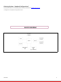
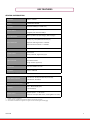
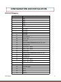
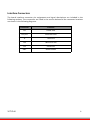
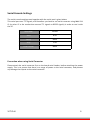
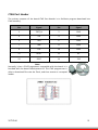
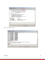
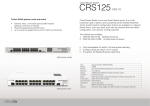
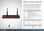
WPJ344
User Manual
TABLE OF CONTENTS
REVISION HISTORY......................................................................................................... 2
REASONS USING DEVELOPMENT KIT.............................................................................2
Ordering Options - Standard Configurations*.........................................................3
BLOCK DIAGRAM............................................................................................................3
KEY FEATURES................................................................................................................ 4
GENERAL INFORMATION.............................................................................................4
INFORMATION ON POWER......................................................................................... 4
CONFIGURATION AND INSTALLATION.......................................................................... 5
GPIO BIT MAPPING.........................................................................................................5
INTERFACE CONNECTORS...................................................................................................6
SERIAL PORT HEADER....................................................................................................... 7
SERIAL CONSOLE SETTINGS................................................................................................ 8
PRECAUTION WHEN USING SERIAL CONVERTER........................................................ 10
SERIAL CONVERTER PIN LAYOUTS....................................................................................... 9
JTAG PORT HEADER...................................................................................................... 10
ETHERNET CONNECTORS................................................................................................. 11
JTAG PROCESS.............................................................................................................. 12
BUILD AND INSTALL PROCESS (FOR OPENWRT FIRMWARE ON COMPEX MYLO
LOADER)........................................................................................................................15
APPENDIX I................................................................................................................... 16
BOARD FEATURES.......................................................................................................... 19
TOP SIDE OF BOARD..................................................................................................19
1
REVISION HISTORY
Revision
Rev 1.0
Information / Changes
First release for WPJ344 BareBoard
REASONS USING DEVELOPMENT KIT
The Development Kit is especially useful for customers who are developing their firmware. Below are the reasons how we have made it
more user-friendly for you.
PURPOSE
WPJ344
WHY IS DEVELOPMENT KIT USEFUL?
Develop Open-WRT firmware on
WPJ344 (using uboot loader)
Serial Converter can be used to debug the
Open-WRT firmware on uboot loader.
Port Own Firmware Over to WPJ344
Serial Converter can be used to debug the
Serial Output messages.
Port Own Firmware and Loader
Over to WPJ344
Serial Converter can be used to debug the
Serial Output messages.
JTAG Programmer can be used to load in your
loader.
2
Ordering Options - Standard Configurations*
Currently item codes are not available, please contact our sales team at [email protected]
* Configurations are subjected to change without notice
BLOCK DIAGRAM
WPJ344
3
KEY FEATURES
GENERAL INFORMATION
PROCESSOR
Atheros AR9344
MEMORY
128MB DDR2 SDRAM
NOR FLASH
NOR Flash 8MB (Up to 16MB max.)
PHYSICAL PORTS
RADIO SUPPORTED
9.2mm height mini-PCIE slot
2 Gigabit ports with Auto-MDI/X
802.11a/c 802.11a/n,802.11b/g/n, 802.11a/b/g/n
Serial (TTL) / JTAG (ARM-standard 20 pin )
DEBUG INTERFACE
Optional JTAG Programmer** available
Optional Serial Converter*** available
OPERATING TEMPERATURE
LED INDICATORS
-20°C to 70°C
6 LEDs total:
Power, Ethernet, Signal LED 1,2,3,4
Status LED
OTHER FEATURES
Push-Button Reset
Surge Arrestors (Optional)
DIMENSIONS
117 mm x 105mm x 17 mm
ENCLOSURE
support MMJ344
INFORMATION ON POWER
POWER OVER ETHERNET
TYPICAL OPERATING POWER
DC SUPPLY
MINIPCIE SLOTS
Passive PoE: 24-48V, IEEE 802.3af/at PoE (HV)
Passive PoE: 12-24V(LV)
5W
24V ~ 48V DC Supply (HV)
9V~24V DC(LV)
Support power : 3.3V and 5V
supports all Compex WLE series, including 802.11ac radio)
*
Depend on Order Configuration
** JTAG Programmer available to reprogram the flash in case of loader corruption.
*** Serial Converter available to change the TTL signals on board to RS232 signals for debugging
WPJ344
4
CONFIGURATION AND INSTALLATION
GPIO Bit Mapping
GPIO Bit
WPJ344
Description
0
Jtag
1
Jtag
2
Jtag
3
Jtag
4
J1 12th pin
5
SPI Flash
6
SPI Flash
7
SPI Flash
8
SPI Flash
9
J23 third pin
10
J23 2nd pin
11
J1 2nd pin
12
Reset button SW1&SW2 and J10 11th pin
13
J1 fourth pin
14
J32 2nd pin,DS19
15
J30 2nd pin,DS20
16
J1 sixth pin
17
Reset button SW1&SW2 and J10 11th pin
18
J1 eighth pin
19
J1 tenth pin
20
21
J31 2nd pin,DS21
J33 2nd pin,DS22
22
J32 2nd pin,DS19
23
J2 power
24
J50 USB signal
25
26
J5 5V
J9 5V
27
J6 3.3V
5
Interface Connectors
The board interface connector pin assignments and signal descriptions are included in the
following sections. The connectors are listed in the section below and the connector locations
are shown in the following diagrams.
WPJ344
Connector
Function
J25
Power Jack
J12/J13
Ethernet Ports
J5
JTAG Port
J14
Mini-PCIE Slot
J23
Serial Port
SW2
Reset Button
6
Serial Port Header
The Serial Port (J23) Header signaling is shown in the following table.
Pin
Signal
1
VCC – 3.3V
2
UART 0 Transmit
Data
3
UART 0 Receive
Data
4
GND
Note:
Our Serial port Implementation requires an external
high-impedance serial port not usually available
with the serial ports of the notebooks/computers.
You will need a Serial Converter available in the
market. For our customers’ convenience, it is
bundled together with the board Development Kit.
WPJ344
7
Serial Console Settings
The serial console settings used together with the serial port is given below.
This serial port uses TTL signals, and therefore you have to use serial converter using MAX-211
IC (or other IC in the market that convert TTL signals to RS232 signals) in order to use it with
the PC.
Baud Rate
115200
Data
8 Bit
Parity
None
Stop
1 Bit
Flow Control
None
Precaution when using Serial Converter
Please attach the serial converter first on the board serial header, before attaching the power
supply. This is to ensure that there is no surge of power to the serial converter, and prevent
any damage the chipset on the serial converter.
WPJ344
8
Serial Converter Pin Layouts
Cables on the serial converters are provided. You can use the 6 Pin (Fixed) to 4 Pin (Fixed)
provided. The pin layouts of the serial converters for use with the board are as follows:
Pin Assignment
(Serial Converters)
Signal
(Serial Converters)
Connected to Pin on
WPJ344
Signal
(WPJ344)
Pin 1
VCC(3.3V) – Red
Pin 1
VCC (3.3V)
Pin 2
TX – Blue
Pin 5
RX
Pin 4
RX - Green
Pin 3
TX
Pin 6
GND – Black
Pin 7
GND
Arrangement of Cables on Serial
Converter to the board
WPJ344
Arrangement of Cables on the board
itself
9
JTAG Port Header
The primary purpose of the board JTAG Port Header is to facilitate program download into
Flash memory.
Pin
Signal
Pin
Signal
1
TRST_N
2
GND
3
TDI
4
GND
5
TDO
6
GND
7
TMS
8
GND
9
TCK
10
GND
11
RESET
12
NC
13
DINT
14
3V3
Note:
Normally, it has a JTAG Programmer compatible with the board. It is
bundled with the board Development Kit. This JTAG programmer is
able to download file onto the Flash, and thus recover a corrupted
loader.
WPJ344
10
Ethernet Connectors
The board contains 2 X 10/100/1000 Base-T Ethernet Channels. The Ethernet Channels are
available through standard 8-pin RJ45 connectors.
Ethernet Connectors(P1/P2) signaling is shown below.
WPJ344
Pin
Signal
1
MX1+
2
MX1-
3
MX2+
4
MX3+
5
MX3-
6
MX2-
7
MX4+
8
MX4-
11
JTAG Process
Minimum Requirement
1. OCD Commander ver2.5.4
2. upbios.tst file (same for all Compex device)
3. uboot.bin file
4. JTAG cable
Steps
1. Install the OCD Commander to your PC
2. Plug the JTAG cable to the JTAG port of the device
3. Run OCD Commander Program
Set "Target Processor" for the particular device
Click "OK"
4.If there is this error message “Error Response from INITIALIZE....”, please check the JTAG
cable connection. Close the OCD Commander Program and go back to Step 3.
5. Click on the “Macro” and choose a specific .mac file.
WPJ344
12
6. Let it run until u see “go”
WPJ344
13
7.
Open command prompt
8.
tftp upbios.tst
9.
tftp uboot.bin (please observe the DIAG LED is off)
10. If either step 9 or step 10 fail, please start from step 3 again.
11. Power off the device and unplug JTAG cable
12. Power on the device and tftp the firmware into the device.
13. Reboot when done.
WPJ344
14
Build and Install Process
(For OpenWRT firmware on uboot Loader)
Minimun Requirement
1:OpenWRT will only be supported on WPJ344 with 8MB NOR flash and above.
2:Please ensure that the Ethernet connection is able to ping address = 192.168.1.1
Compiling OpenWRT on WPJ344 + ath9k with patches from Compex.
Recommended Linux host: CentOS 6.x, Debian 6.x
During the first build of openwrt, about 300MB of various source files
will be downloaded from the internet.The downloaded files will be put in openwrt/dl.
Patches from Compex (support ath9k): sdkowrt-130603.tar.bz2
For first build:
$ cd
$ tar jxf sdkowrt-130603.tar.bz2
$ cd sdkowrt-130603
$ make
The compiled firmware is in:
sdkowrt-130603/openwrt/bin/ar71xx/openwrt-ar71xx-generic-wpj35-squashfs-factory.img
For subsequent build:
$ cd
$ cd sdkowrt-130603/openwrt
$ make
Compiling OpenWRT on WPJ344 + ath10k for 11ac radios, with patches from Compex.
Recommended Linux host: CentOS 6.x, Debian 6.x
During the first build of openwrt, about 300MB of various source files
will be downloaded from the internet.The downloaded files will be put in openwrt/dl.
Patches from Compex (support ath10k): sdkath10k-130716.tar.bz2
For first build:
$ cd
$ tar jxf sdkath10k-130716.tar.bz2
$ cd sdkath10k-130716
$ make
The compiled firmware is in:
sdkath10k-130716/openwrt/bin/ar71xx/openwrt-ar71xx-generic-wpj344-squashfs-factory.img
For subsequent build:
$ cd
$ cd sdkath10k-130716/openwrt
$ make
15
WPJ344
For WPJ344, use WPJ35 firmware, they use the same firmware
OpenWRT Firmware will be in bin/openwrt-ar71xx-wpJ344.bin
Upgrade Firmware with Serial Console
Power on the device, press Esc button from Keyboard. It would be directed to the u-boot
loader mode.
Open the tftp server (Tftpd32.exe) and select the location of firmware folder.
To flash the firmware type the following the command
#cpximg <copy the file’s name>
Wait to complete the firmware loading. Reboot the device after update successfully.
Upgrade Firmware using TFTP [uboot loader version is b130802 onwards
Press and hold the reset button while power up the board.
Release the button after 1 second
Wait for the Diagnostic led to blink fast.
Open the command prompt and type the following command.
#tftp –i 192.168.1.1 put <firmware.img>
Diagnostic led is always on while writing flash.
Diagnostic led blinks slowly after flash firmware.
Power off and power on again to reboot the device.
Default Configurations
LAN (bridge eth0+ath0):
IP Address: 192.168.1.1
Wireless (ath0):
Driver:ath9K/ath10K
Mode: ap
ESSID: OpenWRT
IP Address: 192.168.1.1
Please refer to http://madwifi.org/ for more information.
Use of Compex Patches
1. MAC Address from loader
2. Can detect that it is a Compex board
WPJ344
16
Appendix I
Board Features
7
6
5
8
4
9
3
2
1
TOP SIDE OF BOARD
No:
Feature
1
Reset button
2
DC Jack
Descriptions
For board reset and startup mode control
24V ~ 48V DC Supply (HV)
9V~24V DC(LV)
3
WAN port
WPJ344
10/100/1000 Base T Ethernet port
17
4
LAN port
10/100/1000 Base T Ethernet port (POE in)
5
Serial port
Serial port connection header
6
JTAG port
JTAG jumper header for programming
7
mini-PCIE slot
8
AR9344
9
Radio
WPJ344
9.2mm height mini-PCIE slot
802.11a/c 802.11a/n,802.11b/g/n, 802.11a/b/g/n
On-board 11abgn radio
18