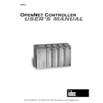
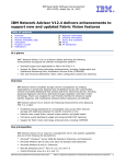
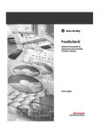
1
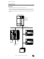
Modified September 28, 1999 5:26 pm
Manual No. EM335-0
DEVICENET SLAVE MODULE
Introduction
This manual describes DeviceNet slave module FC3A-SX5DS1 used with the OpenNet Controller to interface with the
DeviceNet network.
Read this chapter to understand the DeviceNet system setup and the slave module specifications. For general information
about safety precautions, installation, wiring, and dimensions, see the OpenNet Controller user’s manual EM333.
OpenNet Interface Module
The OpenNet Controller can be linked to three major open networks; INTERBUS, DeviceNet, and LONWORKS. For communication through these networks, OpenNet interface modules are available. Mounting the DeviceNet slave module
beside the OpenNet Controller CPU module makes a slave station used as an I/O terminal in a DeviceNet network. The
slave station can transfer I/O data to and from the master station just as an ordinary I/O module in a distributed network.
DeviceNet Slave Module Features
Since the FC3A-SX5DS1 module conforms to the DeviceNet specifications, the OpenNet Controller can be linked to
DeviceNet networks consisting of DeviceNet compliant products from many different vendors, such as I/O terminals, sensors, drives, operator interfaces, and barcode readers.
The transmit/receive data quantity can be selected from 0 through 8 bytes (64 bits) in 1-byte increments. One DeviceNet
slave module enables the OpenNet Controller CPU module to transmit 64 bits and receive 64 bits at the maximum to and
from the DeviceNet master station.
About DeviceNet
DeviceNet has been originally developed by Allen-Bradley of the USA as a network for sensors, actuators, and other
discrete devices, and later the specifications have been opened. Now, major automotive manufactures and various industries employ the DeviceNet networks.
DeviceNet Features
The network configuration is based on the bus system. The basic network consists of a trunkline-dropline topology, and
multi-drop or daisy-chain configuration is also possible.
The DeviceNet protocol is based on CAN (Controller Area Network) which has been widely used for networks on automobiles, making it possible to configure reliable networks with high noise immunity.
Transmission Distance and Nodes
The maximum transmission distance is 500 meters when using a thick trunk cable at a data rate of 125k baud, and the
maximum quantity of nodes is 64 including a master station.
DeviceNet is a registered trademark of Open DeviceNet Vendor Association, Inc. (ODVA).
OPENNET CONTROLLER DEVICENET SLAVE MODULE USER’S MANUAL
1
Modified September 28, 1999 5:26 pm
DEVICENET SLAVE MODULE
System Setup
Various DeviceNet compliant devices can be connected to the DeviceNet network.
The DeviceNet network requires a DeviceNet master module available from other vendors. The OpenNet Controller can
make up a slave station by installing the FC3A-SX5DS1 module to the right of the OpenNet Controller CPU module.
A maximum of seven OpenNet interface modules and analog I/O modules can be mounted with one OpenNet Controller
CPU module.
DeviceNet Master Station
DeviceNet
STATUS
MODULE NET
ADDRESS/ERROR
Example:
Rockwell Automation
SLC Processor
with 1747-SDN
DeviceNet Scanner
DeviceNet Network
POWER
POW
MNS
IO
RUN
ERROR
HSC OUT
COM A
NO
H/L
DR1
DR0
NA5
NA4
NA3
NA2
NA1
NA0
0
1
2
3
4
5
6
7
10
11
12
13
14
15
16
17
B
RS485
Z HSC
OUT A B G +24V 0V
IDEC SX5D Communication Terminal
idec
IDEC
OpenNet Controller
CPU Module
I/O Module
DeviceNet Slave Module
FC3A-SX5DS1
IDEC SX5D Communication Terminal
Other DeviceNet Compliant Devices
2
OPENNET CONTROLLER DEVICENET SLAVE MODULE USER’S MANUAL
Modified September 28, 1999 5:26 pm
DEVICENET SLAVE MODULE
Parts Description
Expansion Connector
(1) Module ID
(5) Status LED
(2) DIP Switch
(4) Color Label
(3) Network Interface Connector
OpenNet Interface Module for DeviceNet
Module Name
DeviceNet Slave Module
Type No.
FC3A-SX5DS1
(1) Module ID
FC3A-SX5DS1 indicates the DeviceNet slave module ID.
(2) DIP Switch
10-pole DIP switch for setting node address, data rate, and output hold/load off
(3) Network Interface Connector
(4) Color Label
(5) Status LED
For connecting the DeviceNet communication cable
A five-color label is located beside the connector on the FC3A-SX5DS1 module. Connect each of the
five different-color wires of the DeviceNet communication cable to the terminal of a matching color.
Label and Wire Insulation Color
Name
Black
V–
Blue
CAN_L
Bare Wire
Drain
White
CAN_H
Red
V+
Indicates operating status
Indicator
Status
—
POW
(power)
MNS
(module/network status)
Module power OFF
Green
ON
Module power ON
—
OFF
Power OFF or Dup_MAC_ID test not completed
Flash
Normal operation (communication not established)
ON
Normal operation (communication established)
Green
Red
—
IO
(I/O status)
OFF
Description
Green
Red
Flash
Minor fault (temporary network error)
ON
Critical fault
OFF
I/O inactive (communication not established)
Flash
I/O idle (communication established)
ON
I/O active
ON
I/O error or communication interrupted
OPENNET CONTROLLER DEVICENET SLAVE MODULE USER’S MANUAL
3
Modified September 28, 1999 5:26 pm
DEVICENET SLAVE MODULE
Specifications
General Specifications
Communication Interface
Power Voltage Range
11 to 25V DC
Current Draw
Approx. 25 mA
Isolation
Between control circuit and communication terminal: Photocoupler isolated
Insulation Resistance
Between communication terminal and FG: 10 MΩ minimum (500V DC megger)
Dielectric Strength
Between communication terminal and FG: 1000V AC, 1 minute (10 mA maximum)
Vibration Resistance
10 to 57 Hz, amplitude 0.075 mm; 57 to 150 Hz, acceleration 9.8 m/sec2 (1G);
10 sweep cycles each in 3 axes (total 80 minutes) (IEC1131)
Shock Resistance
147 m/sec2 (15G), 11 msec, 3 shocks each in 3 axes (IEC1131)
Altitude
Operation: 0 to 2000m
Transportation: 0 to 3000m
Operating Temperature
0 to +55°C (no freezing)
Operating Humidity
30 to 90% RH (no condensation)
Storage Temperature
–25 to +75°C
Storage Humidity
30 to 90% RH (no condensation)
Corrosion Immunity
Free from corrosive gases
Mounting
Snap-on mount on 35-mm DIN rail
Weight (approx.)
180g
Communication Specifications
• Data Rate and Transmission Distance
Data Rate
Max. Cable Distance
for 100% Thick Cable
Max. Cable Distance
for 100% Thin Cable
Max. Drop Line
Length
Max. Total Drop
Line Length
500k baud
100m
100m
6m
39m
250k baud
250m
100m
6m
78m
125k baud
500m
100m
6m
156m
• Maximum Number of Stations in the Network
64 stations (including a master)
• Communication Data Length
Transmit:
Receive:
0 to 8 bytes (selectable in 1-byte increments)
0 to 8 bytes (selectable in 1-byte increments)
• Network Interface Connector
In the module:
To the cable:
MSTB2.5/5-GF-5.08AU (made by Phoenix Contact)
FRONT-MSTB2.5/5-STF-5.08AU (made by Phoenix Contact)
• Communication Cable (Special DeviceNet Cable)
• Terminator
Thick Cable Type No.
Thin Cable Type No.
Maker
1485C-P1A50
1485C-P1-C150
Rockwell Automation
For details about cables, consult Rockwell Automation.
Terminators must be connected to both ends of the DeviceNet network. When
setting up a network, either connect commercially-available terminators at
both ends of the network or connect the following resistor to the branch taps
at both ends of the network.
Metal film resistor: 121Ω, ±1%, 1/4W
4
OPENNET CONTROLLER DEVICENET SLAVE MODULE USER’S MANUAL
Modified September 28, 1999 5:26 pm
DEVICENET SLAVE MODULE
Wiring DeviceNet Cable
Precautions for Wiring
• Do not run the network cable in parallel with or near power lines, and keep the network cable away from noise sources.
• Power down the DeviceNet slave module before starting wiring. Make sure of correct wiring before powering up the
DeviceNet slave module.
• Use the special DeviceNet cable for connecting the network.
• A five-color label is located beside the connector on the DeviceNet slave module. Connect each of the five differentcolor wires of the cable to the terminal of a matching color.
• When using thick cables, only one wire can be connected a terminal of the network interface connector. To connect two
wires of thick cables, use a device tap.
• Tighten the mounting screws of the network interface connector to a recommended torque of 0.3 to 0.5 N-m.
• Tighten the terminal screws of the network interface connector to a recommended torque of 0.5 to 0.6 N-m.
• Either connect commercially-available terminators at both ends of the network or connect the following resistor to the
branch taps at both ends of the network. Connect the terminator between the CAN_H (white) and CAN_L (blue) lines.
Metal film resistor: 121Ω, ±1%, 1/4W
Ferrules, Crimping Tool, and Screwdriver for Phoenix Terminal Blocks
The screw terminal block of the network interface connector can be wired with or without using ferrules on the end of the
cable. Applicable ferrules for the terminal block and crimping tool for the ferrules are listed below. The screwdriver is used
to tighten the screw terminals on the DeviceNet slave module. These ferrules, crimping tool, and screwdriver are made by
Phoenix Contact and are available from Phoenix Contact.
Type numbers of the ferrules, crimping tool, and screwdriver listed below are the type numbers of Phoenix Contact. When
ordering these products from Phoenix Contact, specify the Order No. and quantity listed below.
DeviceNet slave modules are connected to the network using special DeviceNet thick or thin cables, each cable consisting
of three different sizes of wires listed below.
• Ferrule Order No.
Applicable Wire Size
mm2
AWG
0.25
24
0.5
20
0.75
18
1.0
18
1.5
16
2.5
14
For 1-wire connection
Phoenix Type
Order No.
AI 0,25-8 YE
32 00 85 2
AI 0,5-8 WH
32 00 01 4
AI 0,75-8 GY
32 00 51 9
AI 1-8 RD
32 00 03 0
AI 1,5-8 BK
32 00 04 3
AI 2,5-8 BU
32 00 52 2
For 1-wire Connection
For 2-wire connection
Phoenix Type
Order No.
—
—
AI-TWIN 2 x 0,5-8 WH
32 00 93 3
AI-TWIN 2 x 0,75-8 GY
32 00 80 7
AI-TWIN 2 x 1-8 RD
32 00 81 0
AI-TWIN 2 x 1,5-8 BK
32 00 82 3
—
—
Dimension
A
0,25-8 YE
4.5 mm
0,5-8 WH
0,75-8 GY
1-8 RD
6.0 mm
1,5-8 BK
2,5-8 BU
For 2-wire connection
Ferrule
A
8.0 mm
AI
AI
AI
AI
AI
AI
Pcs./Pkt.
Ferrule
AI-TWIN
AI-TWIN
AI-TWIN
AI-TWIN
B
2
2
2
2
x 0,5-8 WH
x 0,75-8 GY
x 1-8 RD
x 1,5-8 BK
100
100
100
100
100
100
Dimension
B
7.0 mm
8.0 mm
8.0 mm
• Crimping Tool and Screwdriver Order No.
Tool Name
Crimping Tool
Screwdriver
Phoenix Type
CRIMPFOX UD 6
SZS 0,6 x 2,5
Order No.
12 04 43 6
12 05 04 0
Pcs./Pkt.
1
10
OPENNET CONTROLLER DEVICENET SLAVE MODULE USER’S MANUAL
5
Modified September 28, 1999 5:26 pm
DEVICENET SLAVE MODULE
DIP Switch Settings
DIP switches are inside the protective lid. After setting the DIP
switches, replace the lid into position.
ON
NO
1
All DIP switches are set to off before shipping from factory.
H/L
2
Set the DIP switches to select the node address (MAC ID: media
access control identifier), data rate, and output hold/load off.
DR1
3
DR0
4
Do not set the DIP switches to the “Selection Prohibited” positions.
NA5
5
NA4
6
NA3
7
NA2
8
NA1
9
NA0
10
Node Address (MAC ID)
Node Address
0
1
2
3
4
5
6
7
8
9
10
11
12
13
14
15
16
17
18
19
20
21
22
23
24
25
26
27
28
29
30
31
NA0
OFF
ON
OFF
ON
OFF
ON
OFF
ON
OFF
ON
OFF
ON
OFF
ON
OFF
ON
OFF
ON
OFF
ON
OFF
ON
OFF
ON
OFF
ON
OFF
ON
OFF
ON
OFF
ON
NA1
OFF
OFF
ON
ON
OFF
OFF
ON
ON
OFF
OFF
ON
ON
OFF
OFF
ON
ON
OFF
OFF
ON
ON
OFF
OFF
ON
ON
OFF
OFF
ON
ON
OFF
OFF
ON
ON
NA2
OFF
OFF
OFF
OFF
ON
ON
ON
ON
OFF
OFF
OFF
OFF
ON
ON
ON
ON
OFF
OFF
OFF
OFF
ON
ON
ON
ON
OFF
OFF
OFF
OFF
ON
ON
ON
ON
Data Rate
Data Rate
125k baud
250k baud
500k baud
(Selection Prohibited)
6
NA3
OFF
OFF
OFF
OFF
OFF
OFF
OFF
OFF
ON
ON
ON
ON
ON
ON
ON
ON
OFF
OFF
OFF
OFF
OFF
OFF
OFF
OFF
ON
ON
ON
ON
ON
ON
ON
ON
NA4
OFF
OFF
OFF
OFF
OFF
OFF
OFF
OFF
OFF
OFF
OFF
OFF
OFF
OFF
OFF
OFF
ON
ON
ON
ON
ON
ON
ON
ON
ON
ON
ON
ON
ON
ON
ON
ON
NA5
OFF
OFF
OFF
OFF
OFF
OFF
OFF
OFF
OFF
OFF
OFF
OFF
OFF
OFF
OFF
OFF
OFF
OFF
OFF
OFF
OFF
OFF
OFF
OFF
OFF
OFF
OFF
OFF
OFF
OFF
OFF
OFF
Node Address
32
33
34
35
36
37
38
39
40
41
42
43
44
45
46
47
48
49
50
51
52
53
54
55
56
57
58
59
60
61
62
63
NA0
OFF
ON
OFF
ON
OFF
ON
OFF
ON
OFF
ON
OFF
ON
OFF
ON
OFF
ON
OFF
ON
OFF
ON
OFF
ON
OFF
ON
OFF
ON
OFF
ON
OFF
ON
OFF
ON
NA1
OFF
OFF
ON
ON
OFF
OFF
ON
ON
OFF
OFF
ON
ON
OFF
OFF
ON
ON
OFF
OFF
ON
ON
OFF
OFF
ON
ON
OFF
OFF
ON
ON
OFF
OFF
ON
ON
Output Hold or Load Off
DR0
OFF
ON
OFF
ON
DR1
OFF
OFF
ON
ON
Output/Load
LOAD OFF
HOLD
H/L
OFF
ON
OPENNET CONTROLLER DEVICENET SLAVE MODULE USER’S MANUAL
NA2
OFF
OFF
OFF
OFF
ON
ON
ON
ON
OFF
OFF
OFF
OFF
ON
ON
ON
ON
OFF
OFF
OFF
OFF
ON
ON
ON
ON
OFF
OFF
OFF
OFF
ON
ON
ON
ON
NA3
OFF
OFF
OFF
OFF
OFF
OFF
OFF
OFF
ON
ON
ON
ON
ON
ON
ON
ON
OFF
OFF
OFF
OFF
OFF
OFF
OFF
OFF
ON
ON
ON
ON
ON
ON
ON
ON
NA4
OFF
OFF
OFF
OFF
OFF
OFF
OFF
OFF
OFF
OFF
OFF
OFF
OFF
OFF
OFF
OFF
ON
ON
ON
ON
ON
ON
ON
ON
ON
ON
ON
ON
ON
ON
ON
ON
NA5
ON
ON
ON
ON
ON
ON
ON
ON
ON
ON
ON
ON
ON
ON
ON
ON
ON
ON
ON
ON
ON
ON
ON
ON
ON
ON
ON
ON
ON
ON
ON
ON
System Reserve
System Reserve
Fixed to
(Selection Prohibited)
NO
OFF
ON
Modified September 28, 1999 5:26 pm
DEVICENET SLAVE MODULE
Link Register Allocation in the CPU Module
DeviceNet communication data is stored to link registers in the OpenNet Controller CPU module and the data is communicated through the DeviceNet slave module.
Since seven functional modules including the DeviceNet slave module can be mounted with one OpenNet Controller CPU
module, link registers are allocated depending on the position where the DeviceNet slave module is mounted.
Link Register Allocation Numbers
Allocation Number
L*00
L*01
L*02
L*03
L*04
L*05
L*06
L*07
L*12
L*13
L*14
L*24
Area
Data area
Data area
Data area
Data area
Data area
Data area
Data area
Data area
Status area
Status area
Status area
Reserved area
Function
Receive data
Receive data
Receive data
Receive data
Transmit data
Transmit data
Transmit data
Transmit data
Error data
I/O counts
Connection status
Software version
Description
Stores received data from the network
Stores received data from the network
Stores received data from the network
Stores received data from the network
Stores transmit data for the network
Stores transmit data for the network
Stores transmit data for the network
Stores transmit data for the network
Stores various error codes
Stores the byte counts of transmit/receive data
Stores the allocation choice byte
Stores the system software version
R/W
Read
Read
Read
Read
Write
Write
Write
Write
Read
Read
Read
Read
Note: A number 1 through 7 comes in place of * depending on the position where the functional module such as OpenNet
interface module or analog I/O module is mounted. Consequently, operand numbers are automatically allocated to each
functional module in the order of increasing distance from the CPU module, starting with L100, L200, L300, through L700.
Error Data (Status Area) L*12
L*12
b15 b14: unused b13
b12-b9: unused
b8
b7-b0: unused
When an error occurs, the MNS or IO LED on the DeviceNet slave module goes on or flashes depending on the error and
a corresponding bit in the link register goes on. The status LED goes off when the cause of the error is removed. The error
data bit remains on until the CPU is powered up again or reset.
b15 (initialization error)
This bit goes on when the CPU module fails to acknowledge the completion of initialization for communication with the
DeviceNet slave module.
b13 (I/O error)
This bit goes on when an error occurs during communication through the CPU bus.
b8 (communication fault)
This bit goes on when a communication fault is detected.
I/O Counts (Status Area) L*13
L*13 b15-b12: transmit bytes
b11-b8: receive bytes
b7-b0: unused
This link register stores the transmit and receive byte counts selected in the Function Area Setting > Open Bus in
WindLDR.
Connection Status (Status Area) L*14
L*14
b15-b8: allocation choice
b7-b0: unused
This link register stores the data of the allocation choice byte.
Soft Version (Reserved Area) L*24
L*24 b15-b12: major revision
b11-b8: minor revision
b7-b0: unused
This link register stores the system software version number. [Example] Version 1.3 — 1: major revision, 3: minor revision
OPENNET CONTROLLER DEVICENET SLAVE MODULE USER’S MANUAL
7
Modified September 28, 1999 5:26 pm
DEVICENET SLAVE MODULE
Function Area Setting for DeviceNet Slave Station
The quantity of transmit/receive data for DeviceNet network communication is specified using the Function Area Setting
in WindLDR. The OpenNet Controller CPU module at the DeviceNet slave station recognizes functional modules automatically at power-up and exchanges data with the DeviceNet master station through the link registers allocated to each slave
station (node).
Since these settings relate to the user program, the user program must be downloaded to the OpenNet Controller after
changing any of these settings.
Programming WindLDR
1. From the WindLDR menu bar, select Configure > Function Area Settings. The Function Area Setting dialog appears.
2. Select the Open Bus tab.
Configure Communication
Master Module Check Box
Check this box only when
the remote I/O master
module is used.
Quantity of Nodes Connected
When using the remote I/O master module, specify the quantity
of nodes from 1 through 32.
Slave Station
Transmit/Receive
Data Quantity (Bytes)
When using OpenNet interface modules for DeviceNet,
INTERBUS, or LONWORKS,
specify the data bytes to
communicate through each
OpenNet interface module.
Transmit/Receive Bytes 0 to 8
(default: 8 bytes)
This value determines the data
quantity 0 through 8 bytes to
communicate with the DeviceNet
or other master module.
For the example on the next
page, select 8 transmit bytes and
4 receive bytes for Module 1.
3. Select transmit and receive data bytes for the slave module position 1 through 7 where the slave module is mounted.
4. Click the OK button and download the user program to the OpenNet Controller.
8
OPENNET CONTROLLER DEVICENET SLAVE MODULE USER’S MANUAL
Modified September 28, 1999 5:26 pm
DEVICENET SLAVE MODULE
Programming a User Program on WindLDR
The OpenNet interface module exchanges data between the open network and the link registers in the CPU module allocated to the OpenNet interface module, depending on the slot where the OpenNet interface module is mounted.
To create a communication program for an OpenNet interface module, first determine the slot number where the OpenNet
interface module is mounted, and make a program to write data to link registers allocated to transmit data and to read data
from link registers allocated to receive data.
Example: When an OpenNet interface module is mounted in the first slot of all functional modules
MOV(W)
S1 –
65535
D1 R
L104
REP
4
MOV(W)
S1 R
L100
D1 R
D0
REP
2
I0
I1
65535 → L104 through L107
When input I0 is on, constant 65535 (FFFFh) designated by source operand S1 is moved to four link registers L104 through L107 designated by
destination operand D1. All 64 bits (8 bytes) in link registers L104
through L107 are turned on. Since link registers L104 through L107 are
for transmit data, the data is transmitted to the network.
L100·L101 → D0·D1
When input I1 is on, 32-bit (4-byte) data in two link registers L100 and
L101 designated by source operand S1 is moved to data registers D0 and
D1 designated by destination operand D1. Since link registers L100 and
L101 are for receive data, communication data is read from the network
to L100 and L101, then moved to data registers D0 and D1.
Starting Operation
Set up the OpenNet Controller CPU and DeviceNet slave modules, and download the user program to the CPU module.
Connect the DeviceNet slave module to the DeviceNet network using DeviceNet cables. Power up the CPU module and
start the CPU module to run, then DeviceNet communication starts. The delay until the communication starts after powerup depends on the size of the user program and the system setup.
While the CPU is stopped, data exchange between the CPU and DeviceNet slave modules is halted, but communication
with the DeviceNet network continues.
Data exchange between the CPU and DeviceNet slave modules is asynchronous with the user program scanning in the
CPU module.
OPENNET CONTROLLER DEVICENET SLAVE MODULE USER’S MANUAL
9
Modified September 28, 1999 5:26 pm
DEVICENET SLAVE MODULE
Transmission Time
The response time of the DeviceNet network varies greatly depending on such factors as the quantity of nodes, data bytes,
and DeviceNet system setup. To determine the accurate response time, confirm the response time on the actual network
system.
The following example describes a response time in a DeviceNet system comprising IDEC SX5D series communication
terminals.
Example: DeviceNet Transmission Time
• System Setup
PLC:
1747-L532 (SLC5/03 CPU made by Rockwell Automation)
Master:
1747-SDN (SLC500 DeviceNet Scanner Module made by Rockwell Automation)
Slave:
SX5D-SBM16K (8pt transistor source input / 8pt transistor sink output)
SX5D-SBM16P (8pt transistor sink input / 8pt transistor protect source output)
SX5D-SBR08 (8pt relay output)
Data Rate:
125k baud
Operation Mode: Communication according to the scan list in the master
• System Operation (Data Flow)
(1) SX5D-SBM16K sends 8-input data to the master, and the master sends 8-output data to SX5D-SBM16K.
(2) SX5D-SBM16P sends 8-input data to the master, and the master sends 8-output data to SX5D-SBM16P.
(3) SX5D-SBM16K sends 8-input data to the master, and the master sends 8-output data to SX5D-SBR08.
• Calculating the Response Time
Response time = Input processing time (slave) + Communication time (slave to master) + Data processing time (master
and PLC) + Communication time (master to slave) + Output processing time (slave)
• Measured Value of Response Time
SX5D-SBM16K Input ON/OFF → SX5D-SBM16K Output ON/OFF response time = Approx. 18 msec
PLC (1747-L532)
Node 0 (MAC ID = 0)
DeviceNet
STATUS
MODULE NET
ADDRESS/ERROR
DeviceNet Master
(1747-SDN)
Power Supply Module
DeviceNet Network
10
Node 1 (MAC ID = 1)
Node 2 (MAC ID = 2)
Node 3 (MAC ID = 3)
SX5D-SBM16K
SX5D-SBM16P
SX5D-SBR08
OPENNET CONTROLLER DEVICENET SLAVE MODULE USER’S MANUAL
Modified September 28, 1999 5:26 pm
DEVICENET SLAVE MODULE
Troubleshooting in DeviceNet Operation
Three LED indicators are provided on the DeviceNet slave module. When a trouble occurs during DeviceNet communication, these status LEDs go on or flash depending on the error. When the LEDs go on or flash, locate the error referring to
the table described below.
Probable Causes for Network Errors
When a trouble occurs during DeviceNet communication, the following causes are suspected.
• Strong external noise
• The power voltage to the DeviceNet slave module has dropped below the minimum operating voltage (at least momentarily).
• Use of a faulty communication line, incorrect cable, or transmission over the rated distance
• Improper terminator
DeviceNet Master Module fails to recognize the slave module
Status LEDs on Slave Module
POW
MNS
IO
OFF
OFF
OFF
Cause
Power is not supplied to
the OpenNet Controller
CPU module
Action
Supply 24V DC to the OpenNet Controller CPU module
Plug in the expansion connector correctly
Plug in the communication connector correctly
Green
ON
OFF
OFF
Power is not supplied to
the DeviceNet interface
Connect the DeviceNet power lines red (V+) and black (V–)
correctly
Supply 11-25V DC to the DeviceNet power line
Plug in the communication connector correctly
Set the data rate correctly using DIP switches
Green
ON
OFF
Green
ON
Master is not found
Set the data rate of the master station correctly
Make sure that network wiring is correct in the entire
DeviceNet network, without short circuit or disconnection
Connect terminators (121Ω) at both ends of the network
Plug in the communication connector correctly
Set the data rate correctly using DIP switches
Green
ON
Red ON
Green
ON
Physical communication
trouble or duplicate MAC
ID exists in the network
Set the MAC ID correctly using DIP switches
Make sure that nodes with duplicate MAC ID does not exist
in the same network
Make sure that network wiring is correct in the entire
DeviceNet network, without short circuit or disconnection
Connect terminators (121Ω) at both ends of the network
Supply power to the DeviceNet master
Make sure of correct settings for the master
Plug in the communication connector correctly
Green
ON
Green
Flash
Green
ON
Slave operates normally, but is not recognized by the master
Set the data rate correctly using DIP switches
Set the MAC ID correctly using DIP switches
Make sure that network wiring is correct in the entire
DeviceNet network
Connect terminators (121Ω) at both ends of the network
OPENNET CONTROLLER DEVICENET SLAVE MODULE USER’S MANUAL
11
Modified September 28, 1999 5:26 pm
DEVICENET SLAVE MODULE
Communication error occurs
Status LEDs on Slave Module
POW
MNS
IO
OFF
OFF
OFF
Cause
Power is not supplied to
the OpenNet Controller
CPU module
Action
Supply 24V DC to the OpenNet Controller CPU module
Plug in the expansion connector correctly
Plug in the communication connector correctly
Green
ON
Red ON
Physical communication
trouble exists in the
network
Green
ON
Make sure that network wiring is correct in the entire
DeviceNet network, without short circuit or disconnection
Make sure that the network is not affected by noise
Make sure that the master is operating
Green
ON
Red ON
Green
ON or
Red
Flash
Data from the master
does not arrive
Plug in the communication connector correctly
Make sure that network wiring is correct in the entire
DeviceNet network, without short circuit or disconnection
Make sure that the network is not affected by noise
Make sure of correct settings for the master
Green
ON
Green
Flash
Communication with
the master is not
established
Green
ON
Make sure that the slave is not stopped by power-down or
other causes (if automatic recovery is enabled at the master, communication resumes when power is restored at the
slave)
Plug in the communication connector correctly
Make sure that network wiring is correct in the entire
DeviceNet network, without short circuit or disconnection
Supply 11-25V DC to the DeviceNet power line
OpenNet Controller link registers cannot receive data from the network correctly
Status LEDs on Slave Module
POW
MNS
IO
Cause
Action
Make sure of correct settings for the master
ON or
OFF
ON or
OFF
ON or
OFF
Incorrect setting or
communication error
Set the transmit/receive bytes in Function Area Settings
correctly
Make sure of correct link register numbers
See “DeviceNet Master Module fails to recognize the slave
module” and “Communication error occurs” described
above
OpenNet Controller link registers cannot send out data to the network correctly
Status LEDs on Slave Module
POW
MNS
IO
ON or
OFF
ON or
OFF
ON or
OFF
Cause
Action
Make sure of correct settings for the master
12
Incorrect setting or
communication error
See “DeviceNet Master Module fails to recognize the slave
module” and “Communication error occurs” described
above
OPENNET CONTROLLER DEVICENET SLAVE MODULE USER’S MANUAL