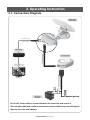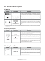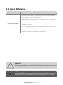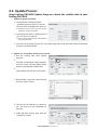
1
REV. 1.0
Fully
ly Automatic
Motorised
torised
orised
sed
ed Satellite
Sate te TV System
Syst
Syste
User’s manual
Customer Help Line: 1300 139 255
Support Email: [email protected]
Website: www.satkingpromax.com.au
www.satkingpromax.com.au
Contents
1. General Information
1-1.
1-2.
1-3.
Introduction . . . . . . . . . . . . . . . . . . . . . . . . . . . . . . . . . . . . . . . . . . . . . . . . . . . . . . . . . . . . . . . . . . . . . . . . . . . . . . . . . . . . . 2
Proper use and Operation . . . . . . . . . . . . . . . . . . . . . . . . . . . . . . . . . . . . . . . . . . . . . . . . . . . . . . . . . . . . . . . . . . . . . . 3
Safety Notes . . . . . . . . . . . . . . . . . . . . . . . . . . . . . . . . . . . . . . . . . . . . . . . . . . . . . . . . . . . . . . . . . . . . . . . . . . . . . . . . . . . . 4
2. Contents
2-1.
2-2.
Components Bundle . . . . . . . . . . . . . . . . . . . . . . . . . . . . . . . . . . . . . . . . . . . . . . . . . . . . . . . . . . . . . . . . . . . . . . . . . . . . 5
Name of parts . . . . . . . . . . . . . . . . . . . . . . . . . . . . . . . . . . . . . . . . . . . . . . . . . . . . . . . . . . . . . . . . . . . . . . . . . . . . . . . . . . . 6
3. Operating Instruction
3-1.
3-2.
3-3.
Connection Diagram . . . . . . . . . . . . . . . . . . . . . . . . . . . . . . . . . . . . . . . . . . . . . . . . . . . . . . . . . . . . . . . . . . . . . . . . . . . 7
Functional Description . . . . . . . . . . . . . . . . . . . . . . . . . . . . . . . . . . . . . . . . . . . . . . . . . . . . . . . . . . . . . . . . . . . . . . . . . 8
Quick Reference . . . . . . . . . . . . . . . . . . . . . . . . . . . . . . . . . . . . . . . . . . . . . . . . . . . . . . . . . . . . . . . . . . . . . . . . . . . . . . . . 10
4. Program update
4-1.
4-2.
Connection Diagram for updating . . . . . . . . . . . . . . . . . . . . . . . . . . . . . . . . . . . . . . . . . . . . . . . . . . . . . . . . . . . . . 11
Update Process . . . . . . . . . . . . . . . . . . . . . . . . . . . . . . . . . . . . . . . . . . . . . . . . . . . . . . . . . . . . . . . . . . . . . . . . . . . . . . . . . 12
5. Trouble Shooting
5-1.
Trouble Shooting
........................................ . . . . . . . . . . . . . . . . . . . . . . . . . . . . . . . . . . . . . . .
14
6. Specifications
6-1.
6-2.
Dimension . . . . . . . . . . . . . . . . . . . . . . . . . . . . . . . . . . . . . . . . . . . . . . . . . . . . . . . . . . . . . . . . . . . . . . . . . . . . . . . . . . . . . . 15
Specifications . . . . . . . . . . . . . . . . . . . . . . . . . . . . . . . . . . . . . . . . . . . . . . . . . . . . . . . . . . . . . . . . . . . . . . . . . . . . . . . . . . . 15
7. Camping Car Installation
7-1.
7-2.
7-3.
7-4.
7-5.
Required space for the SatKing PRO MAX . . . . . . . . . . . . . . . . . . . . . . . . . . . . . . . . . . . . . . . . . . . . . . . . . . . . .
Equipment for Installation . . . . . . . . . . . . . . . . . . . . . . . . . . . . . . . . . . . . . . . . . . . . . . . . . . . . . . . . . . . . . . . . . . . . . .
Installation . . . . . . . . . . . . . . . . . . . . . . . . . . . . . . . . . . . . . . . . . . . . . . . . . . . . . . . . . . . . . . . . . . . . . . . . . . . . . . . . . . . . . .
Battery connection . . . . . . . . . . . . . . . . . . . . . . . . . . . . . . . . . . . . . . . . . . . . . . . . . . . . . . . . . . . . . . . . . . . . . . . . . . . . .
Installation diagram . . . . . . . . . . . . . . . . . . . . . . . . . . . . . . . . . . . . . . . . . . . . . . . . . . . . . . . . . . . . . . . . . . . . . . . . . . . .
16
18
18
22
22
1. General Information
1-1. Introduction
These instructions describe the functions and operation of the SatKing PRO MAX auto skew
satellite system.
Correct and safe operation of the system can only be ensured by following these instructions.
Your SatKing PRO MAX is an intelligent satellite TV reception antenna system which can
align itself towards a preset satellite automatically as long as the system is located within the
footprint of the selected satellite.
The SatKing PRO MAX only occupies requisite space while it performs the necessary adjustments with the slim and agile antenna body.
For general operation, please ensure that the system always has a clear view of the Northern
Sky. If the satellite‘s signal beam is interrupted by obstacles such as buildings or trees, the
unit will not function and no satellite TV signal will be received.
For more information on general use of this unit consult your local dealer for assistance.
SatKing PRO MAX User manual - 2
1-2. Proper use and operation
This product has been designed for fixed installation on vehicles with maximum speeds of
130 km/h. It is designed to automatically aim an antenna at geostationary television satellites.
The power to the system is supplied by a standard vehicle electrical system with a rated
voltage of 12 or 24 Volts DC.
Use of the equipment for any other purpose to the one specified is not permitted.
Please also note the following instructions from the manufacturer:
• It is not possible to add or remove components on this product.
• The use of other components other than those originally supplied.
• When completing Installation you or your contractor must strictly follow all instructions in the
supplied User Manual. Failure to follow the user manual may cause damage to the SatKing Pro Max or
your vehicle.
• The product does not require any regular maintenance; all service must be carried out at approved
service centre’s.
• All relevant guidelines of the automotive industry must be observed and complied with.
• The equipment must only be installed on solid vehicle roofs.
• Avoid cleaning your vehicle with the mounted satellite system in a drive-through car wash or a car wash
with a high-pressure cleaner.
• The SatKing PRO MAX comes with a 3 year warranty, for full warranty details please visit our website
www.satkingpromax.com.au
• After Sales Support Line 1300 139 255 or [email protected]
SatKing PRO MAX User manual - 3
1-3. Safety Notes
In order to ensure that your SatKing PRO MAX works properly you
must ensure that it is following by the Operating Instructions in
this manual and used as intended purpose.
When it is correctly installed, the antenna automatically assumes
the rest position when the ignition is switched on and locks itself.
If the system cannot fully be removed due to user's negligence,
then it is your responsibility to check that the antenna is properly
stored in safe.
Please also note that different legal requirements are applied to
the operation of electrical and electronic equipment in different
countries. As the user of this equipment, you are responsible for
yourself ensuring compliance with the relevant laws and regulations.
The manufacturer does not take liability for direct or indirect
consequential damage of the system, motor vehicles or other
equipments by reason of unsuitable battery usage or erroneous
installation or wrong wire connection.
SatKing PRO MAX User manual - 4
2. Contents
2-1. Components Bundle
5C Power Cable
(7m)
Main unit
Mounting plate
Controller
Controller bracket
Power Input Cable
Receiver cable (12m – Grey color)
(×2 : In case of twin output)
Cable holder
Cable gland
Manual
Spanner
M4x20(11), M8 Flanged Nut(4)
SatKing PRO MAX User manual - 5
User manual
2-2. Name of parts
Main unit
Antenna
LNB
Elevation : 5° ~ 90°
Skew pivot :
-60° ~ +60°
Main body : 390° Turning
Mounting plate
Base
to Receiver (Option)
to Controller
to Receiver
Controller
GPS status light
HOME status light
Satellite light
HOME button
OK button
Satellite CCW / CW button
Power switch
Bracket
to Main unit
Power port : DC 12~24V
USB port : For F/W upgrade
SatKing PRO MAX User manual - 6
3. Operating Instruction
3-1. Connection Diagram
MAIN UNIT
Receiver cable
(Grey color)
5C Power Cable
RECEIVER
BATTERY
Ignition
-
+
Power Input Cable
TV
CONTROLLER
to Ignition
Use the 5C Power cable to connect between the controller and antenna.
The controller cable looks similar to the antenna receiver cable but you can distinguish
them by the color and labeling.
SatKing PRO MAX User manual - 7
3-2. Functional Description
A. Power On
Function
Description
“Power” Switch
i. When the all cable connections are completed, switch on
with the “Power Switch” button on the top of the controller.
"Home Status" light
Stand By "ON"
ii. If the antenna was at home position, “Home status” light
will be solid on to show it is ready to use.
"Home Status"
light Flashing
iii. If the antenna was not in the home position, “Home status”
light will flash, and the antenna will return to the home
position within a maximum 2 minutes. Then will be solid
on.
Turning into "ON"
◆
Operation
The “Home position” means antenna completely folded down to the body part which is the basic position for
functioning.
B. Selecting the satellite
Function
Description
Operation
i. Once antenna and controller are connected, you can select
& change the satellite as you desire.
“Satellite
CCW / CW button” Light ii. Select the preferring satellite using the “CCW / CW”
buttons, then press the “OK” button to accept the setting.
“OK” Button
iii. If you select the wrong satellite, you can re-search target
satellite using the “CCW / CW” button, then press the “OK”
button to accept the new setting.
C. Searching the satellite
Function
Description
Operation
i. After the satellite selection, “Home Status” light will go off
and the LED light of the selected satellite will start flashing.
“Satellite” light
ii. Once selected satellite has been found, the LED light of the
satellite will become solid.
SatKing PRO MAX User manual - 8
D. Changing the satellite
Function
Description
Operation
“Satellite
CCW / CW button” Light i. If you want to change desired satellite, you can change the
target satellite using the “CCW / CW” buttons, then press
the “OK” button to select the new satellite.
“OK” Button
E. Back to Home position
Function
Description
“HOME” Button
Operation
i. Whenever you wish to return the antenna back to the Home
position, press and hold the“Home” button for a few seconds.
F. GPS LED light
Function
Description
Operation
i. GPS LED confirms the current location from 24 GPS satellites
in the world.
“GPS” light
ii. When your SatKing PRO MAX identifies a GPS signal, GPS
LED light will remain on, regardless if the antenna is
pausing or moving.
GPS can help to search for the satellite faster & catch the
optimum satellite signal, and assist SatKing PRO MAX to
acheive the best elevation & skew angle.
iii. Also, while program updating, the GPS LED light will flash
to show the update procedure is processing. During this
time, GPS LED light on doesn’t mean the unit is communicating with GPS satellite.
SatKing PRO MAX User manual - 9
3-3. Quick Reference
Classification
Description
1. Switch on with the “Power switch” button on the top of the controller.
2. Upon power on, all LED will flash twice.
3. Wait until “HOME Status” light & one “Satellite LED” light, which you set
previously or the first satellite in the controller (Turksat), remain solid on.
Operating
(Searching the satellite)
4. Select the desired satellite using the “CCW / CW” buttons, then press the
“OK” button to select.
5. IF the satellite LED light starts flashing, please wait for a while until it
turns to keep the LED on steadily.
6. When the satellite LED light stays on, the selceted satellite has been
located and a signal can be seen on the satellite TV.
WARNING
When you physically move the SatKing Pro Max, the unit must be returned
to the home position to prevent damage to the unit.
NOTE
SatKing PRO MAX will be automatically folded back to HOME position if the
vehicle moves faster than 10km/h, when the reception of GPS is stable.
SatKing PRO MAX User manual - 10
4. Program update
4-1. Connection Diagram for updating
※ The SatKing PRO MAX is pre-programmed with the relevant satellite’s
information. Upgrades are only required if the satellite providers change
their technical parameters.
“USB port is used for firmware upgrade only”
MAIN UNIT
5C Power Cable
CONTROLLER
MINI USB type
A type
BATTERY
USB cable
Power Input Cable
PC
Simply connect the Controller to PC using USB cable.
USB cable is not included in the package.
SatKing PRO MAX User manual - 11
4-2. Update Process
Using SatKing PRO MAX Update Program, refresh the satellite data of your
SatKing PRO MAX.
i. Update Program download
① Download the SatKing PRO MAX
Update Program to your PC from our
website (www.satkingpromax.com.au ).
※ Download driver file, if your OS doesn’t
support the update program.
② Download the newest satellite data to
your PC from our website .
※ Be sure your product location and download
correct location file.
③ Connect the controller to your PC using USB cable, then install the SatKing PRO MAX Update
Program you downloaded.
ii. Update the 10 satellites which are pre-stored
④ Run the SatKing PRO MAX update
program.
⑤
Click “file” on left-upper side on program,
and click "open" to select folder which
contains downloaded satellite data.
⑥
Select folder and click the “OK” button.
⑦ When folder is opened, select file and
click the “Open” button.
⑧ The data of 10 satellites are shown to
you, but they are not modifiable by
yourself.
⑨ Check the Port Setting, then click the
“CONNECT” button.
SatKing PRO MAX User manual - 12
⑩ Once “SEND_DATA” button is activated,
click the “SEND_DATA” button.
⑪ Wait until green bar reaches to the end
and "Send OK" message box is popping
up.
⑫ Once "Send OK" message box is shown,
update is completed.
iii. Update USER 1~2
• USER 1~2 are for extra addition of your
desired satellites which are not pre-stored.
• After download the SatKing PRO MAX
update program, start it.
Then tick the box on USER 1~2 which
you wish to update, and write the
satellite data in the box by yourself.
Then follow the procedure from ⑨ as
above.
• To get detailed information of satellite data, please contact your local distributor.
NOTE
Do not turn off the power or disconnect the cable before the update process
is complete.
To find out more about how to update the SatKing Pro Max go to our
website www.satkingpromax.com.au
SatKing PRO MAX User manual - 13
5. Trouble shooting
There are a number of common issues that can affect the signal reception quality or the
operation of the SatKing PRO MAX. The following sections address these issues and
potential solutions.
A. No function when you power on the Controller
i. Check again all the cable connections have been made correctly.
Connection between the power and controller
Connection between the controller and the antenna. Make sure that the right port of the
antenna should be connected to the controller.
ii. Check if the power input cable has been damaged.
iii. Check car battery polarities(+/-) and ignition of power input cable.
B. Fail to search the selected satellite
i. Satellite signals can be blocked or degraded by buildings, trees.
Make sure there are no obstructions in a northerly direction.
ii. Check your program of Controller often, and get the latest updates for your SatKing PRO MAX.
C. Mechanical problems
i. If the antenna does not move into desired position.
Try to power OFF/ON again.
ii. If the antenna makes a noise whilst remaining static.
Try to power OFF/ON again. If problem persists, please contact your local distributor for
assistance.
D. Other issues
i. If the system has been improperly wired, it will not operate properly. Contact your local
distributor for assistance of cable damage.
SatKing PRO MAX User manual - 14
6. Specifications
6-1. Dimension
MAX 57.5cm
MIN 27.0cm
27.0cm
51.8cm
56.9cm
6-2. Specification
MODEL NAME
SatKing PRO MAX
Weight
19.6 kg
Work Condition
Stationary
Polarization
Linear (Horizontal / Vertical)
LNB Output
Dual Output
LNB Input Frequency
11.7 ~ 12.75 GHz
LNB Output Frequency
1000 ~ 2050 MHz
Angle Range
(EL) 5° ~ 90° / (AZ) 390° / (SK) -60° ~ +60°
Satellite Searching Time
120 seconds (average)
Power Requirement
DC 12~24V
Power Consumption
84W (in searching)
Operating Temperature
-30°C ~ +60°C
SatKing PRO MAX User manual - 15
7. Camping Car Installation
7-1 . Required space for the SatKing PRO MAX
Please allow that there is enough space around the SatKing Pro Max for flat antenna section
to complete a full 360° scan of the sky and return to the home position.
Vehicle rear
Center of
the rotation unit
20.5cm
44cm
59.5cm
51.8cm
A : Radius 30cm
up to a height 5cm
B : Radius 35cm
up to a height 12cm
C : Radius 50cm
up to a height 30cm
Driving direction
C : Radius 50cm
B : Radius 35cm
A : Radius 30cm
30cm
12cm
5cm
SatKing PRO MAX User manual - 16
7-2. Equipment for Installation
3
2
1
4
6
9
11
10
5
7
8
12
1
Silicone
2
Spanner
3
M4x20(11), M8 Flanged Nut(4)
4
Cable gland
5
Cable holder
6
Friction tape
7
2mm drill bit, 15mm drill bit
8
Power drill
9
5C Power Cable (7m)
10
Receiver cable (12m-Grey color)
11
Mounting plate
12
Cleaner
※ Mounting Plate direction
Driving direction
7-3. Installation
A. Mounting plate Installation on the vehicle roof
A-1
A-2
FRONT
Clean the surface with cleaner
Locate mounting plate in the center of vehicle
roof
A-3
A-4
Attach friction tape outside of the mounting
plate by 4mm away from plate edges
Put aside the mounting plate to apply silicone
within the guided tape line but leave 2cm gap
from the line
SatKing PRO MAX User manual - 17
B. Assemble 6pcs of M4x20 bolt at the fix bracket
B-1
B-2
Put back the mounting plate on the silicone
applied and make 6holes (2mm) with power drill
B-3
Apply silicone on the holes
B-4
Assemble bolts
Re-apply silicone to cover bolts assembled
C. Apply siliconebetween fix bracket and friction tape
C-1
C-2
Apply silicone around mounting plate
C-3
Remove friction tape and get dry
Tidy the area silicone applied
C-4
The image you will see. Place main unit on the
top of fixed plate
SatKing PRO MAX User manual - 18
D. Fix the mounting plate with 4 pcs of bolts using spanner
D-1
D-2
E. Cable holder installation 1
E-1
E-2
Equipment to initiate Cable holder installation
Insert cables like picture
E-3
Arrange cable holder in front of (30cm apart from) antenna center by facing open side of cable holder
toward projected part of the mounting plate. Then attach friction tape outside of cable holder
E-5
E-4
Make 15mm drill hole in the center of the tape
marking
Insert Receiver & 5c Power cable through the
hole
SatKing PRO MAX User manual - 19
F. Cable holder installation 2
F-2
F-1
Place cable holder in the tape marked and make
3 of 2mm drill holes
F-3
F-4
Fix cable holder on the car roof with 3 of M4x20
screws
F-5
Tidy silicon
Apply silicone around cable holder
Apply silicone around and on the top of screws
F-6
Remove friction tape
G. Connect 5C cable to the controller(middle) and grey cable to the receiver(Left)
G-1
SatKing PRO MAX User manual - 20
7-4. Battery connection
2
1
Power Input Cable
Check the Polarity of Car Battery (+/-)
3
4
Ignition
+
-
Use Power Input Cable to Connect Car Battery (+/Polarities have to be matched) and Ignition Terminal
Use Power Input Cable and 5c Power Cable to
Connect to Controller
5
6
Fix the Controller Bracket
Place the Controller at where you want
7-5. Installation diagram
TV
MAIN UNIT
RECEIVER
Receiver cable
(Grey color)
BATTERY
Power Input Cable
SatKing PRO MAX User manual - 21
5C Power Cable
CONTROLLER