1
_
USOO5396427A
Unlted States Patent [191
[11] Patent Number:
Piehl et al.
[45]
[54]
5,250,935 10/1993 Jonker et a1. ............ .. 364/43l.04 X
METHOD AND APPARATUS FOR
Date of Patent:
DETERMINING RELATIVE
CONTRIBUTIONS 0F INDIVIDUAL
Mar. 7, 1995
OTHER PUBLICATIONS
CYLINDERS OF INTERNAL COMBUSTION
ENGINE
[75] Inventors: James R. Piehl; Robert D. Braun;
Craig F. Govekar, Gurnee, Ill.
.
Snap-on Tools Corporation manual for MT3000 En
gine Analyzer. No date.
glam-01113 plrools 501501-1310; :nanual for MT30OO‘42O
Gary s. Wollert, all ofKenosha, Wis.;
we‘
“nee
‘0 e‘
O a 6'
Primary Examiner—Kevin J. Teska
-
[73] Asslgnee. Snap-on Incorporated, Kenosha, W15.
[21] Appl. No.: 848,274
[22] Flled:
Mar‘ 9’ 1992
[51]
[52]
5,396,427
Int. Cl.6 .......................................... .. G01M 15/00
US. Cl. ........................ .. 364/431.04;364/431.07;
Assistant Examiner-Collin W. Park
Attorney, Agent’ or Firm__Emrich & Dithmar
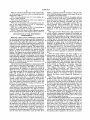
[57]
ABSTRACT
A linearly moving external part of a multi-cylinder
internal combustion engine is contacted with a hand
held contact tachometer for producing a waveform
364/551.01; 364/565; 73/116; 73/518; 73/529;
signal which, along with a signal responsive to the igni
324/ 161; 324/163; 324/379
tion of each cylinder, are applied to an engine analyzer
[58] Field of Search .................... .. 364/431.03, 431.04,
processor for display of a single engine cycle of the
364/431.07, 551.01, 565; 73/116, 488, 489, 518,
527, 529, 117.2, 117.3; 324/378, 379, 160, 163,
waveform signal on the CRT oscilloscope of the engine
analyzer. The variations and amplitude of the wave
form signal correspond to speed variations of the mov
178, 161
[56]
References Cited
ing part over an engine cycle to give an indication of the
relative power contnbut1ons of the 1nd1v1dua1 cylinders.
Cylinder ignition markers and cylinder zone markers
U-S- PATENT DOCUMENTS
4,301,678 11/1981 Full et a1. ............................ .. 73/116
4,348,893 9/1982 Hendrix et a1. ..
........ .. 73/116
4,525,781 6/1985 KOnOmi et al
364/431-01
ifhroeder at al- -,
,
Immerman
....
4,625,546
12/1986 Sugo et al.
4,800,378 l/1989 Putrow etal.
4,843,870
-------- .... ..
their ignition order. Each cylinder zone marker is de
layed a predetermined time from its corresponding
'
'
'
'
‘
'
‘
‘
.... ..340/722
73/116
glider
lhgin?lg?efeng
mad?“
and mglcitetshthfe tlrtlle perm‘:
n gW C
“Fespon 5 0 61g“ ‘on even
of the correspondmg cylmder
7/1989
Citron et al. . . . .
. . . . .. 73/116
5,056,360 10/1991
Dosdall et a1. ..
........ .. 73/116
5,182,512
Braun et a1. .................. .. 324/378 X
l/1993
are respectively displayed at the top and bottom of the
screen, respectively corresponding to the cylinders in
12 Claims, 3 Drawing Sheets
US. Patent
Mar. 7, 1995
Sheet 1 0f 3
5,396,427
__~_
E
w.
Q
E
a‘
may
mma3m‘as am,gmas
ML5%;
mEEE4maama./24,
N
\
l/
E
I
2
5
m
4
m
4o DUI]DUBUUDUDUUDUUUUUUUUUUUUUUU‘U1DUI]
DAY MM'DO'YY
Rm 600
VACUUM WAVEFORM
AVG vAcuuM
0.0 in Hg
/
PRIOR ART
GRID
CURSORS
@/OFF
ON/ E
VACUUM
VERTICAL
PROBE ZERO POSITION
IEI/ Dc
COUPLING
NEXT
PAGE
US. Patent
Mar. 7, 1995
Sheet 2 0f 3
5,396,427
51
/
CYUNDER TEST MENU
E29 4
/52
TO PROCEED, PRESS A FUNCT\ON
KEY BELOW OR CHOOSE ANOTHER
MENU FROM THE KEYBOARD
\
\
\
\
CRAN KING
AMPS
CYLIN DER CYLIN DER
VACUUM
SHORTING TIME BALANCE WAVEFORM
BAR GRAPH
BAR GRAPH
BAR GRAPH
?3
X
\
POWER
BALANCE
RETURN
TO
WAVEFORM
START
61/
54
62~ 0“ MM'DM POWER BALANCE’ WAVEFORM
""5
10/4?I
81/
LEF-V % “1;”
'
HH‘MM‘SS AM /60
i ‘a.’
i
ll%1\71
84
'
'
l
'
'
-
n
.
l
|
I
|
|
‘
‘
|
l
|
-/:-5--§"E-'§-:'-:-
67
821 7711
= Z8 1
£‘\76 §"\78 i'pebi sieeci'aedg 4
663..’ emu
I
i /75i
-
C41 /79
$176 5“
'
.cuksoké wAvEF'oRM vemx'cm.
E/OFF
o~/_lqEl SIZESELECT POSITION
[F1 IIF-ZjlF? ||=4 II~FS1IFG1
D“ MM‘DD'YY
POWER BALANCE WAVEFORM HH‘MM‘SS AM
60
RPM 719
P1575
/
\
...|:~.:
612m
cunsons
-
-
.
.
|
.
I
I
I
.I
|
|
'
I
I
'
|
I
WAVEFORM VERTICAL
[($11 /OFF ou/l?] SlZESELECT POSITION
|
I
|
l
:
_ US. Patent
Mar. 7, 1995
5,396,427
Sheet 3 0f 3
H9 7
I01 I99
‘
WAVEFORM
POWER
BALANCE
CHECK
<KEYBOARD>
102" INITIALIzATIoN
RPM UPDATE
(FIG-6)
1
(FIG-7)
103/
105
104/
MEMORY 0R
FREEZE
CHECK
CHECK PROBE
I0 I=oR PwR.
BALIcONNEcTIoN
106
?g 5
RPM UPDAT
104
.
E
I______? ____ __T____—|
i
I
MINI
D'STRIBUTORLESS
‘
RPM UPDATE
MARY 0R
RPM UPDATE
IGNITION
WITH
WITH
CHARACTERIZATION
ENsINEsYNc
*1 sYNc
QEEONDARY
ENGINE SYNC
SELECTION
ROUTINE
/
H0
107 /
111
E29 5
112
POWER BALANCE
WAVEFORM
1.0.?
KEYBOARD GHECK
W I
p228???)
II
II
I
F1
F2
F3
F4
GRID
cuRsoRs
wAvEFoRM
VERTICAL
ON/OFF
{I
0N [OFF
SIZE SELECT
I
F5
SELECT
cm “DER no
"4
‘=6
GOTOCYLTEST
POSITION
{I
I
SELECT
(TOGGLE cuRsoR)
uP/ DOWN
ARROWS
|
I
F
———— -—
2°\ I
‘H3
*
I r
SHORT
CYLINDER
>10 CYL.
I
LEFT/RIGHT
KEYS 0-9
SHORT
122
1
VERTICAL
cuRsoR
ADJUST
HORIZONTAL
WAVEFORM
CURSOR
POSITION
ADJUST
MENU KEYS
\IIQ
CYLINDER
SELECT
(>10 cYL)
T
——-—--—-+
123x I
#413
I
r
SELECT
(no on.)
I
I
FREEZE KEY
ENTER Exrr
INVALID
(FREE E)
116/
117
cYLINoER
ADJUST
115
(CYLINDER)
r____ ____‘
\ i
I
—————
\
GOQSQYA'Z‘Q‘NDUER
I
ARROWS
121
KEYS
\m
1
5,396,427
METHOD AND APPARATUS FOR DETERMINING
RELATIVE CONTRIBUTIONS OF INDIVIDUAL
CYLINDERS OF INTERNAL COMBUSTION
ENGINE
2
lar cylinder ignition event and careful attention to the
user’s manual for the contact tachometer is absolutely
required in order to understand its use in connection
with the “Vacuum Waveform” display screen.
SUMMARY OF THE INVENTION
BACKGROUND OF THE INVENTION
1. Field of the Invention
The present invention relates to analysis of the rela
tive power contributions of individual cylinders of an
internal combustion engine and, in particular, relates to
techniques for determining such power contributions
from variations in the engine speed.
2. Description of the Prior Art
The present invention is an improvement of the in
vention disclosed in copending US. application Ser.
No. 604,191, ?led Oct. 20, 1990, now US. Pat. No.
It is a general object of the present invention to pro
vide an improved method and apparatus for determin
ing cylinder power balance in an internal combustion
engine, which avoids the disadvantages of prior tech
niques while affording additional structural and operat
ing advantages.
An important feature of the invention is the provision
of a method of determining cylinder power balance
from engine speed variations during a single engine
cycle, which is relatively simple and easy to perform.
In connection with the foregoing feature, another
feature of the invention is the provision of the method
5,182,512. That application discloses a technique for
determining cylinder power balance in an internal com
of the type set forth which utilizes a digital engine ana
bustion engine. That technique involves utilizing a
lyzer and affords a simple and easily understood display
contact tachometer to detect the speed variations of an
accessible external moving part of an engine, such as a
of the power balance information.
Another feature of the invention is the provision of an
fan belt or the like, the tachometer outputting a signal to
an associated engine analyzer, which may be of the type
apparatus for performing the method of the type set
forth.
sold by Snap-on Tools Corporation under the designa
tion MT3000 and disclosed in copending US. applica
tion Ser. No. 587,357, ?led Sep. 24, 1990, now US. Pat.
No. 5,250,935. Such an engine analyzer includes a num
These and other features of the invention are attained
by providing apparatus for determining the relative
power contributions of individual cylinders of a multi
cylinder internal combustion engine, wherein an engine
ber of probes, adapted for connection to an associated
cycle is the time between consecutive ignition events of
engine, which can detect, among other things, the igni 30 the same cylinder, the apparatus comprising: speed
tion events (spark plug ?rings in the case of gasoline
sensing means for detecting speed variations of the
engines or combustion signals/fuel pulses in the case of
engine during an engine cycle and generating an electri
diesel engines) of each cylinder. The microprocessor of
cal output signal indicative thereof, ignition sensing
the engine analyzer utilizes the output of the contact
tachometer to generate a waveform signal indicative of 35 means for detecting the ignition events of each cylinder,
processing means coupled to the speed sensing means
engine speed variations and displays a single engine
and to the ignition sensing means and responsive to the
cycle of that waveform signal, so that speed variations
output signal for generating a waveform signal repre
from one cylinder cycle to the next can be analyzed. In
sentative of the speed variations of the engine over time,
this regard, an engine cycle is the time period between
consecutive ignition events of the same cylinder and a 40 and display means coupled to the processing means for
cylinder cycle is the time period from the ignition event
displaying a single engine cycle of the waveform signal,
the processing means including means causing the dis
play means to display cylinder zone markers equal in
in the ignition fuing order.
number to and respectively corresponding to the cylin
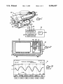
However, that prior system operates to display the
waveform signal on a “Vacuum Waveform” display 45 ders in their ignition order, each zone marker indicating
the time period during which the engine responds to the
screen of the engine analyzer, which screen, in addition
ignition event of the cylinder corresponding to that
to the waveform, displays at the top of the screen indi
zone marker.
cations of the cylinder ignition events in the ignition
The invention consists of certain novel features and a
order and, at the bottom of the screen, indicates cylin
of one cylinder to the ignition event of the next cylinder
der vacuum events in the vacuum order. Such a screen,
designated by the numeral 10, is illustrated, for example,
in FIG. 3, wherein the waveform signal is indicated at
11, the ignition event markers are indicated at 12 and
the vacuum event markers are indicated at 13. The
“Vacuum Waveform” screen is utilized for the wave
form display since it is the only suitable display screen
available with that engine analyzer, but it is not de
signed for the purpose of displaying instantaneous en
gine speed information. Accordingly, that screen dis
plays a number of features and functions relating to
vacuum waveforms which the operator has to disregard
in viewing a power balance waveform. In particular,
the vacuum event markers 13 introduce considerable
confusion, since they are out of phase with the ignition
combination of parts hereinafter fully described, illus
trated in the accompanying drawings, and particularly
pointed out in the appended claims, it being understood
that various changes in the details may be made without
departing from the spirit, or sacri?cing any of the ad
vantages of the present invention.
‘BRIEF DESCRIPTION OF THE DRAWINGS
For the purpose of facilitating an understanding of
the invention, there is illustrated in the accompanying
drawings a preferred embodiment thereof, from an in
spection of which, when considered in connection with
the following description, the invention, its construc
tion and operation, and many of its advantages should
be readily understood and appreciated.
event markers 12 by one-half an engine cycle. Accord 65
FIG. 1 is a block diagrammatic illustration of the
ingly, it is very dif?cult for an operator to determine the
apparatus of the present invention, coupled to an inter
portion of the power balance waveform 11 which cor
nal combustion engine shown in front perspective view,
responded to the response of the engine to any particu
with portions broken away for clarity of illustration;
3
5,396,427
FIG. 2 is a front elevational view of the engine analy
zer of the present invention, which is diagrammatically
illustrated in FIG. 1;
Referring in particular to FIG. 2, the engine analyzer
FIG. 3 is an elevational view of a screen display of a
prior art engine analyzer;
4
display a generally sinusoidal waveform which is indic
ative of the ?uctuations in speed of the engine 20, as will
be explained more fully below.
5 30 has a set of six “sof ” keys, F1 through F6, arrayed
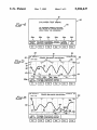
FIG. 4 is a elevational view of the screen display of
along the bottom edge of the CRT screen 33, the func
the engine analyzer of FIG. 2;
tions of which are software controlled and vary with
the mode of operation of the engine analyzer 30, in a
known manner. More speci?cally, the software for
FIG. 5 is an elevational view of another screen dis
play of the engine analyzer of FIG. 2, illustrating a
normal power balance waveform;
controlling the operation of the engine analyzer 30
FIG. 6 is a view similar to FIG. 5, illustrating an
causes an indication of each soft key function to be
abnormal power balance waveform; and
displayed on the screen immediately adjacent to the
key.
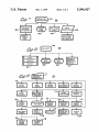
FIGS. 7~9 are flow charts of the computer program
for the microprocessor of the engine analyzer of FIG. 1.
The engine analyzer 30 also has a main keyboard 41
which includes: a numerical keypad 42 including ten
DESCRIPTION OF THE PREFERRED
EMBODIMENT
Referring to FIG. 1, there is illustrated a multi-cylin
keys for digits 0 through 9, respectively; four direction
keys 43 for the directions up, down, right and left; four
function keys 44; six menu keys 45; a reset key 46; and
a HELP key 47. The functions of these various keys in
controlling the operation of the engine analyzer 30 are
der internal combustion engine, generally designated by
the numeral 20, of a type with which the present inven
tion is useful. The engine 20 is shown as a V-6 gasoline
described in greater detail in the aforementioned co
engine, but it will be appreciated that the present inven
tion may be used with any other con?guration of multi
cylinder internal combustion engine. The engine 20 has
a distributor 21 which is coupled by wires 22 to spark 25
plugs 23, respectively positioned for igniting the fuel
pending U.S. application Ser. No. 587,357, to produce a
number of different types of screen displays, including
that illustrated in FIG. 3. The present invention func
tions similarly to that disclosed in co-pending applica
tion Ser. No. 587,357, with the following exceptions,
mixture in each of the several cylinders in standard
fashion. The engine has an output crankshaft 24. A fan
which now will be explained in connection with FIGS.
4-6.
belt 25 is coupled to a pulley 26 at the front end of the
After the engine analyzer has been coupled to an
crank shaft 24 for driving a cooling fan or other associ 30 idling engine in the manner illustrated in FIG. 1, the
ated equipment. Similarly, a generator belt 27 is coupled
operator, by actuating the appropriate one of the menu
to the pulley 26 for driving a generator or alternator 28.
keys 45, calls up the Cylinder Test Menu illustrated in
The crankshaft 24 is also coupled to a ?ywheel or ring
FIG. 4. This display includes a title at 51 and an instruc
gear 29 for coupling to an associated transmission (not
tional message at 52. This particular menu includes six
shown) in a known manner.
35
The present invention includes an engine analyzer 30,
which may be of the type sold by Snap-on Tools Corpo
ration under its designation MT-3000, and includes a
Graph”, “Cylinder Shorting Bar Graph”, “Cylinder
Time Balance Bar Graph”, “Vacuum Waveform”,
microprocessor 31 coupled to a video drive circuit 32
which is, in turn, connected to a CRT oscilloscope 33.
“Power Balance Waveform” and “Return to Start”.
The “Power Balance Waveform” option, selected by
key F5, is the only one which is pertinent to the present
The engine analyzer 30 may include a plurality of input
leads, one of which is a conductor 36 coupled to a
invention. When it is actuated, it calls up the Power
Balance Waveform screen display 60, illustrated, in
pickup 37, which may be an inductive or capacitive
pickup and is adapted to be coupled to the wire 22 for
the No. 1 spark plug 23, i.e., the spark plug for the
cylinder which has been designated by the manufac
45
turer as the ?rst cylinder in the ?ring order. In the case
of a diesel engine a piezoelectric pickup to sense fuel
Engine speed is detected by a contact tachometer 38,
FIG. 5.
The “Power Balance Waveform” screen display 60
includes a title at 61 and an engine RPM display at 62.
It also includes date and time displays at 63 and 64,
respectively. The main portion of the display is a graph
65 which essentially plots engine speed along the verti
pulses, or known pickups for sensing combustion, may
be used in a similar manner.
options, selected by soft keys F1-F6, which are respec
tively labeled at 53a-53f as “Cranking Amps Bar
50
cal axis against time along the horizontal axis. The soft
keys Fl-F4 are respectively labeled at 66a~66d as
which may be of the type disclosed in the aforemen
“Grid On/Off”, “Cursors On/Oft”, “Waveform Size
Select” and “Vertical Position”. The soft keys F1 and
output of which is connected by a cable 39 to the micro
F2 both toggle between ON and OFF conditions, with
processor 31 of the engine analyzer 30. In operation, the 55 the selected condition being highlighted in the corre
encoder wheel of the contact tachometer 38 is held
sponding label display 66a or 66b. When the grid is ON,
against one of the readily accessible, external, linearly
vertical and horizontal grid lines 67 appear on the graph
moving parts of the engine 20, such as the fan belt 25.
65 to facilitate reading the graph.
The encoder wheel rotates at a speed proportional to
The screen 60 also includes ignition event markers 70,
tioned copending application Ser. No. 604,191, and the
the linear speed of the moving engine part with which
it is engaged, which latter speed is, in turn, proportional
to the speed of the engine 20. The contact tachometer
38 responds to the rotation of its encoder wheel to gen
erate an output signal which is in the nature of a ?uctu
ating voltage, the amplitude of which is directly pro
portional to the speed of the engine 20. The signal is
processed by the microprocessor 31, which in turn actu
ates the video drive circuit 32 to cause the CRT 33 to
which comprise highlightable numbers at equidistantly
spaced apart points along the top of the graph 65, re
spectively corresponding to the engine cylinders in
their ?ring order. For purposes of illustration, the dis
play for a four-cylinder engine is illustrated in FIG. 5.
The ignition event markers 70 respectively appear at
the times along the graph 65 at which the ignition
events for the corresponding cylinders occur, i.e., when
the ignition pulse is applied to the cylinder. In horizon
5
5,396,427
6
changes in engine speed and, therefore, the overall am
plitude of the waveform 80 will be less for an engine
tal alignment with the ignition event markers 70 at the
right-end of the graph 65 is the highlighted designation
with more cylinders. This is because the time interval
“IGN” indicated at 71, which designates the function of
the ignition event markers 70.
It is a signi?cant aspect of the invention that the
screen 60 also includes cylinder zone indicia 75 along
the bottom of the graph 65. These indicia comprise a
between cylinder ?rings is smaller, leaving less time for
the engine to slow down between engine ?rings.
It is a signi?cant aspect of the present invention that
the points on the waveform 80 corresponding to cylin
der ignitions are relatively easy to identify because of
the cylinder zone indicia 75. More speci?cally, the ?rst
low point in the waveform 80 within a given cylinder
zone, corresponds to the ignition of that cylinder. Thus,
for example, if the operator starts at the left-end of the
line 77, which is the beginning of the cylinder 1 zone,
and progresses along that zone, the ?rst low point in the
waveform 80 is at 82 and, therefore, this corresponds to
the ignition of cylinder No. l and marks the beginning
of its power stroke.
plurality of equidistantly spaced-apart markers 76 in the
form of short vertical lines, respectively marking the
beginnings of each of the cylinder zones, these markers
76 being interconnected by a horizontal line 77. The
numbers of the cylinders, in their ?ring order, are indi
cated at 78, respectively in the centers of the cylinder
zones, i.e., substantially midway between adjacent
markers 76. At the right-hand end of the horizontal line
77 appears the highlighted designation “CYL”, indi
cated at 79, to designate the function of the cylinder
While the ignition points of the cylinders along the
zone indicia 75.
Each cylinder zone on the graph 65 represents the
waveform 80 are not too dif?cult to identify in a nor
time period during which the engine will respond to the
ignition event for that cylinder. Thus, for example,
mal-operating engine, this is usually not the case for an
abnormally-operating engine. The waveform 90 for
cylinder zone 1 is the time period during which the
such an abnormally-operating engine is illustrated in
engine is responding to the ignition of cylinder 1, and
FIG. 6 and, as can be seen, is much more irregular than
that zone ends with the ignition of cylinder 3, which is
next in the ?ring order, whereupon the engine will
respond to the cylinder 3 ignition. It will be noted that
the start of each cylinder zone, as indicated by the cylin
der zone indicia 75, is delayed or offset a slight distance
in time from the ignition event for that cylinder, as
indicated by the ignition event markers 70. This is be
cause there is a certain time delay from the time the
ignition pulse is applied to a cylinder until ignition oc
curs and the engine actually starts to respond by the
25
the waveform 80. In order to identify the cylinder igni
tions, the operator looks for valleys of the waveform
within each of the cylinder zones. Thus, the valley at 91
marks the ignition of the No. 1 cylinder. The engine
responds by accelerating and decelerating until the
ignition of the No. 3 cylinder at 92. The next valley
occurs at 93 in the cylinder No. 4 zone, and marks the
ignition of that cylinder. It will be noted that this igni
tion occurs somewhat later then the earlier ignitions and
played and, as can be seen, ?uctuates in a generally
sinusoidal manner. The reason that the waveform 80
the engine responds by accelerating very little to a peak
94, then starts to decelerate to the ignition of the No. 2
cylinder at 95. After the ?ring of the N0. 4 cylinder, it
accelerates further to 96 in response to the ?ring of the
No. 2 cylinder.
This waveform 90 indicates that the No. 4 cylinder is
malfunctioning and that that cylinder is not contribut
ing the proper amount of power to the engine. This
power drop could result not only from a mis?ring, but
also from mechanical or fuel system problems. What
and, accordingly, the speed of the moving engine part
ever the source, the faulty cylinder can be identi?ed. It
corresponding piston starting its power stroke. This
offset is predetermined, based on the particular type of
engine being analyzed, and will typically correspond to
at least a 20° rotation of the engine crankshaft 24.
The output of the contact tachometer 38 is displayed
as a waveform 80 on the graph 65. More speci?cally,
one complete engine cycle of the waveform 80 is dis
can be seen that there is a leveling off of the waveform
being monitored ?uctuate, is the intermittent nature of
the power source, i.e., the discrete ignition events of 45 90 at 94a and, in the prior art engine analyzer, an opera
tor might mistake this for the ignition event of a No. 2
individual cylinders spaced apart in time. This results in
cylinder and conclude that there were problems with
a cyclical acceleration and deceleration of the engine
both the Nos. 4 and 2 cylinders. However, with the
crankshaft 24. Each time a cylinder ignition event oc
present invention, it is clear that this is not an ignition
curs, the engine 20 ?rst accelerates and then decelerates
event for the No. 2 cylinder, since it does not occur in
until the ignition event for the next cylinder.
the No. 2 cylinder zone.
The waveform 80 represents a four-cylinder engine
As can be readily appreciated, the advantages af
20 which is operating normally. The ignition of the No.
forded by the cylinder zone indicia 75 of the present
1 cylinder occurs at 81, as indicated by the correspond
invention are even more signi?cant, the greater the
ing ignition event marker 70. This ignition event is re
number of cylinders in the engine, since the peaks and
flected in the movement of the engine at 82 in the wave
valleys of the waveform will be even closer together.
form 80, which marks the initiation of the power stroke
As can be seen from the waveform 90, although there is
for the No. 1 cylinder. The engine responds by acceler
a problem in only one cylinder, this affects the shape of
ating during the power stroke, as at 83, to a peak speed,
the waveform in other cylinder zones. It will be appre
and then begins to slow down or coast, as at 84, until the
ciated that if more than one cylinder is faulty the wave
ignition for the next cylinder in the ?ring order, which
form can become extremely erratic. In such a case, the
is the No. 3 cylinder. As can be seen, the amplitudes of
proper analysis of the waveform can be extremely dif?
the peaks of the waveform 80 are generally the same,
indicating that each of the cylinders is contributing
cult with prior engine analyzers and, therefore, in such
cases the present invention is even more advantageous
approximately the same power to the overall engine
output, which is the desired performance. It will be 65 to the operator.
Referring now to FIGS. 7—9, the operation of the
appreciated that, if the amplitudes of the waveforms are
program 100 for the microprocessor 31 in response to
at the same setting, as determined by the “Waveform
selection of the “Power Balance Waveform” mode
Size Select” function actuated by soft key F3, the
7
5,396,427
from the Cylinder Test Menu of FIG. 4 will be de
scribed. When the function key F5 is actuated, the pro
8
tion of the No. 1 cylinder upon actuation of the F5 soft
key), subsequent actuation of the F6 soft key will cause
the selected cylinder to be shorted at 120.
If the engine does not have more than ten cylinders,
then the direction keys 43 have other functions, con
gram enters the Power Balance Waveform mode at 101
(FIG. 7) and ?rst goes through an initialization se
quence at 102 and then performs a memory or freeze
check to determine if the screen is to display a live
trolled by the F2 and F4 soft keys. If the cursors are
waveform, which is the default condition, or if this is to
be a display of a previously-frozen screen, or if the
waveform to be displayed is one previously saved in
toggled ON by the F2 soft key, then the program will
move the horizontal cursor at 121 in response to actua
long term memory. The program also performs a key
tion of the up and down arrow keys, and will move the
vertical cursor at 122 in response to actuation of the left
board check at 103, an engine RPM update at 104 to
ascertain and display the current engine RPM and a
serial communications routine at 105, whereby the in
and right arrow keys. If the F4 soft key is actuated, the
program will adjust the vertical position of the wave
form at 123 in response to the actuation of the up and
formation to be displayed is passed to the display board
down arrow keys. In this regard, it will be appreciated
in the engine analyzer 30 for driving the CRT screen 33. 15 that the F2 and F4 soft keys are mutually exclusive, i.e.,
In this routine, the program also checks the probe ID to
only one can be active at a time. Thus, for example, if
see that the contact tachometer 38 is properly con
the F4 soft key label is illuminated and the F2 key is
nected.
depressed to toggle the cursors ON, the F2 soft key
Referring to FIG. 8, the RPM update routine 104 is
label will be illuminated and that for the F4 soft key will
entered at 106 and proceeds to 107 to determine if the
be extinguished so that the up/down arrow key can
engine to which the engine analyzer 30 is connected is
have only one function at a time.
a distributorless ignition engine, in which case different
If any other key is pressed the program recognizes it
probe inputs will have to be read, as is explained in
greater detail in the co-pending aforementioned appli
at 124 as an invalid key and gives a suitable indication.
From the foregoing, it can be seen that there has been
cation Ser. No. 587,357. The program also does an 25 provided an improved apparatus and method for deter
RPM update, utilizing the Engine Sync signal at 108 or
the #1 sync signal at 109, depending upon whether a
primary or secondary sync signal is being used, as se
lected by the routine at 110.
Referring to FIG. 9, the keyboard check routine 103
is described in greater detail. This routine is entered at
111 and proceeds to scan the soft key set 40 in the main
keyboard 41 to determine which, if any, keys have been
actuated. If none have been actuated, the program sim
ply proceeds to 112 and will continue in the main loop 35
of the program as is described more fully in the copend
ing application Ser. No. 587,357. Although the F6 soft
key has no label on the Power Balance Waveform
screen 60, illustrated in FIG. 5, it has a hidden or non
mining the relative power contributions of individual
cylinders of a multi~cylinder internal combustion engine
which is much easier to use than prior techniques.
We claim:
1. Apparatus for determining relative power contri
butions of individual cylinders of a multi-cylinder inter
nal combustion engine, wherein an engine cycle is a
time period between consecutive ignition events of the
same cylinder, said apparatus comprising:
(a) speed sensing means for detecting speed variations
of the engine during an engine cycle and generat
ing an electrical output signal indicative thereof,
(b) ignition sensing means for detecting the ignition
events of each cylinder,
displayed function which will return the screen to the
Cylinder Test Menu display 50 of FIG. 4, as indicated at
113. The screen display 60 at FIG. 5 is provided with a
pair of vertical cursors and a pair of horizontal cursors
(0) processing means coupled to said speed sensing
(not shown), with one cursor of each pair being active
at a time, the active ones being selectable by toggling 45
the SELECT key, which is one of the function keys 44,
this function being indicated at 114.
tions of the engine over time, and
((1) display means coupled to said processing means
for displaying a single engine cycle of the wave
form signal from which said relative power contri
If one of the menu keys 45 is pressed, the program
will move to 115 and call up the corresponding menu
screen. If the FREEZE key, which is one of the func
said processing means including means for causing
said display means to display cylinder zone mark
means and to said ignition sensing means and re
sponsive to said output signal for generating a
waveform signal representative of the speed varia
butions are determined,
tion keys 44, is pressed, the program will move to 116
and toggle, i.e., either enter or exit the FREEZE mode.
If the engine to which the engine analyzer 30 is con
nected has more than ten cylinders, as indicated by the
engine identi?cation information entered by the user 55
during setup, the F5 and F6 soft keys will respectively
have labels “Select Cylinder” and “Short Cylinder”
displayed on the Power Balance Waveform screen 60.
In this case, if the F5 soft key is pressed, its label will be
highlighted and the directional keys 43 will be operative
ers equal in number to and respectively corre
sponding to the cylinders in their ignition order,
each zone marker indicating a time period during
which the engine responds to the ignition event of
the cylinder corresponding to that zone marker.
2. The apparatus of claim 1, wherein said speed sens
ing means includes means for detecting speed variations
of an accessible external moving part of the engine.
3. The apparatus of claim 2, wherein said speed sens
60 ing means includes means for detecting linear speed of
to select a cylinder. The number of the selected cylin
the moving part.
ders in the ignition event markers 70 will be high
4. The apparatus of claim 3, wherein said speed sens
lighted. Thus, a higher or lower numbered cylinder can
ing means includes a contact tachometer.
be selected by using the up or down arrows, as at 117,
5. The apparatus of claim 1, wherein said processing
or by using the right and left arrows, as at 118. Any 65 means includes means for causing said display means to
cylinder up to ten can also be selected by using the
display cylinder zone markers comprising a plurality of
numerical keypad 42, as indicated at 119. Once a cylin
substantially equidistantly spaced-apart indicators re
der has been selected (the program will default to selec
spectively positioned at the beginnings of the cylinder
9
5,396,427
zones and corresponding cylinder numbers displayed
respectively substantially in the middles of the cylinder
(a) detecting speed variations of the engine during an
engine cycle and generating an electrical output
signal indicative thereof,
(b) detecting the ignition events of each cylinder,
zones.
6. The apparatus of claim 5, wherein said display
means includes a CRT screen, said processing means
including said means for causing zone markers to be
displayed adjacent to the bottom of the screen.
(c) processing the output signal to generate a wave
form signal representative of the speed variations
7. The apparatus of claim 5, wherein said processing
of the engine over time,
(d) displaying the waveform signal as a graph in
which speed and time are respectively measured
means includes means for causing ignition event mark
ers to be displayed at locations respectively correspond
ing to the times of the ignition events of the cylinders.
8. The apparatus of claim 7, wherein said ignition
event markers include cylinder numbers displayed in
the ignition order.
9. The apparatus of claim 7, wherein said processing
10
ignition event of the next cylinder in the ignition order,
said method comprising the steps of:
along orthogonal axes such that the cylinder cycles
occupy substantially equal distances along the time
axis,
15
means includes means causing said cylinder zone mark
ers to be respectively offset in time from the corre
sponding cylinder ignition event markers by a predeter
mined time period.
(e) displaying adjacent to the graph cylinder zone
markers respectively corresponding to the cylinder
cycles, and
(f) determining said relative power contributions by
comparing the cylinder cycles of the waveform
during a single engine cycle.
10. A method for determining relative power contri
11. The method of claim 10, wherein the detecting
butions of individual cylinders of a multi-cylinder inter - step includes detecting speed of an accessible external
nal combustion engine, wherein an engine cycle is a
moving part of the engine.
time period between consecutive ignition events of the
12. The method of claim 11, wherein the detecting
same cylinder, and wherein a cylinder cycle is the time 25 step includes detecting linear speed of the moving part.
*
*
*
*
*
period from the ignition event of one cylinder to the
35
45
55
65