1
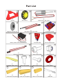
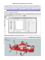
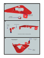
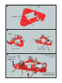
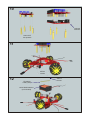
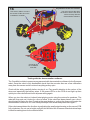
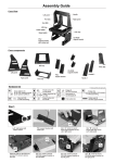
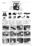
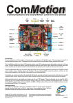
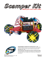
Build your own omni robot Copyright C 2014 by DAGU Hi-tech Electronic Co., Ltd. All rights reserved. No portion of this instruction sheet or any artwork contained herein may be reproduced in any shape or form without the express written consent of DAGU Hi-tech Electronic Co., Ltd. The manufacturer and distributor cannot be held responsible for any damages occurred by mishandling, mounting mistakes or misuse due to non-respect of the instructions contained in this manual. Manufacturer: DAGU Hi-Tech Electronic Co.,LTD WWW.AREXX.COM.CN Manual RS038 Product Description Thank you for selecting the Scamper robot kit as your next do-it-yourself project. This kit will allow you to build an omni wheeled robot that can move in any direction. Using the demo code and IR sensor PCB provided the robot will act as a spinning line follower. The ComMotion controller is also an Arduino shield. Experienced users can add an Arduino controller and use the ComMotion controller as an I²C controlled motor controller. We recommend the SparkFun RedBoard as the larger USB socket used on many Arduino boards can short circuit the ComMotion shield. Product Features 1. High quality anodized aluminium chassis - light weight and strong. 2. Omni wheels with rubber rollers for better traction on smooth floors. 3. Metal geared motors with rear shaft for encoders. 4. Hall-effect encoder on each motor for precise speed control. 5. Pre-programmed ComMotion Shield with demonstration software. Build it now! Realize your dream! Create your next masterpiece! ! Warnings Opened packages cannot be returned. Please check package contents before opening. Read instructions carefully before assembling. Use all tools carefully. Small parts are a choking hazard. Keep this kit away from young children and babies during construction and operation. Not for children under 8 years. Not to be used by children except under adult supervision. Observe correct polarity of the battery. Reverse polarity will permanently damage the controller. Keep dry at all times. Remove the batteries if the robot gets wet. Do not mix battery types. Do not mix partially charged and fully charged batteries. Do not use carbon-zinc or alkaline batteries. Use NiMh batteries only. Remove batteries if the kit is not to be used for a long time. Tools The kit is supplied with all tools required to assemble it. The supplied spanner fits the hex spacers, 3mm nuts and the nut on the switch. A small Philips Head screw driver is also included for use with the 2.5mm and 3mm screws. Part List 1 3 2 1x Chassis 3x Geared motor with cable 6x Omni wheel 5 4 7 8 1x IR sensor PCB 1x Battery holder with switch and cable 10 13 11 17 18 4x 25mm M-F hex spacer 2x 17mm F-F hex spacer 12 3x 3mm Nyloc nut 15 14 12x 3mm x 6mm screw 9 1x Sensor PCB bracket 3x 3mm x 8mm screw 1x IR sensor PCB cable 1x Fiberglass battery strap 1x ComMotion shield 3x Hall effect sensor with cable 3x Magnetic encoder disc 6 6x 2.5mm x 8mm screw 16 3x Fiber washer 19 4x 12mm F-F hex spacer 20 12x cable ties Optional 3D assembly instructions The assembly steps shown in this manual are also available as a series of 3D models drawn in SketchUp. If you have trouble understanding any step in the assembly instructions then you can view that step in 3D. This allows you to view the model from any angle and zoom in on any detail. The 3D models and the installation file for the SketchUp Viewer can be downloaded here: https://drive.google.com/file/d/0B__O096vyVYqT3d0Y1FsVDF3a3c/edit?usp=sharing To open a model, click on the file menu or the open folder icon and select a step from the "Scamper 3D Assembly Manual" file. Open File Once the file is opened you can use the Orbit tool to rotate the model in any direction. Your mouse scroll wheel can be used to zoom in or out. Orbit tool 1 Align the tab with the hole Install the power switch 2 3x8mm screw 3mm nyloc nut Attach sensor PCB to mounting bracket. 3 Mount sensor PCB on the chassis. 3mm nyloc nuts 3x8mm screws 4 3x6mm screws 17mm F-F hex spacers 5 2.5x8mm screws Install the motors. 6 1. Feed the sensor through the hole and bend leads at 90° angle. Feed motor wires through the hole. 3. Gently tighten the cable tie so that wires can still be adjusted. 2. Wrap cable tie around the motor to hold sensor and motor cables in place. 7 Align screws with flat sections on the shaft. 5mm fiber washer 8 Push encoder disc onto rear motor shafts. Leave about 3mm (1/8th) space between encoder disc and sensor. 9 3x6mm screws 12mm Hex Spacers 10 Optional controller 25mm M-F hex spacers 11 3x6mm screws 12 Fiberglass battery strap 6x AA NiMh batteries (not included) 3x6mm screws 13 ! Warning! Connect the wires to the switch. Make sure the switch is "OFF" during assembly to prevent accidental short circuit. Note position of metal tab. 14 Pay attention to the wire colours! You must connect the wires as shown to ensure the robot works correctly with the demonstration software. Wheel 3 M3 Battery + Wheel 2 M1 M2 Wheel 1 15 Encoder 1 Encoder 2 Encoder 3 Pay attention to the wire colours! You must connect the wires as shown to ensure the robot works correctly with the demonstration software. Triangles on PCB indicate signal pin (white wire). 16 Pay attention to the wire colours! Use sensor cable to connect the sensor PCB to A7 on the ComMotion controller. You must connect the wires as shown to ensure the robot works correctly with the demonstration software. Connector A7 on ComMotion controller. Testing with the demonstration software The ComMotion shield comes pre-programmed with demonstration software for the Scamper robot. Once the robot is fully assembled check that the encoder disc are a few millimeters away from the sensor and do not touch anything as they spin. Check all the wiring carefully before turning it on. Pay careful attention to the colour of the wires and especially the battery wires. If the power LEDs on the PCB do not light up then quickly turn the robot off and check all power wiring again. When you turn the robot on it should start playing music using the motors for speakers. The robot will then spin as it looks for a line to follow. If the robot had been placed over a line it should start following the line. Pressing the reset button or cycling the power will toggle the demonstation mode on or off. If the robot just beeps a few times then press reset again. If the robot cannot detect the line then try adjusting the small potentiometer on the sensor PCB fully clockwise. Do not use in bright sunlight, this will blind the IR sensor. Black electrical tape is ideal for making lines for the robot to follow. Optional Controller The Scamper robot kit uses the ComMotion PCB as a "stand alone" controller running demonstration software however the ComMotion PCB can also be used as an I²C motor control shield. The advantage of I²C control is that almost all of your IO pins (except A4 and A5) are free for use with other shields, sensors or circuits. Unfortunately most Arduino boards use a large metal USB connector that will short out many shields including the ComMotion shield. We recommend using the SparkFun RedBoard or any other compatible controller that uses a mini or micro USB connector to avoid this problem. Troubleshooting No Power: Turn off the robot and check that the black wire from the battery holder is connected to the negative battery terminal of the controller PCB. Check that the red wire from the battery holder goes to one of the outer pins on the switch. Check that the red wire from the center pin of the switch goes to the positive battery terminal of the controller PCB. Turn on the switch, if the power LEDs do not light up then check all batteries have their positive terminal pressed against the metal connector in the battery holder. Some battery brands can be a tight fit in the battery holder. This prevents the springs from pushing the battery against the opposite contact. Check your batteries are fully charged and inserted the correct way around. Motors constantly speed up and slow down again: This indicates no signal from the encoder. Please check the encoder wiring carefully as shown in step 15. Make sure the sensor is about 3mm (1/8th of an inch) away from the surface of the magnetic encoder disc. Make sure the encoders are plugged into the correct header on the controller. Motors spin in the wrong direction: When the robot powers up it should spin in a clockwise direction, if one or more motors are spinning in the wrong direction then check that the motor is connected to the correct terminal and that the wire colours match those in step 14. Robot does not follow the line: The IR sensor will not work in bright sunlight. If you are indoors then try closing the curtains. Best conditions are a black line about 15-20mm wide on a light coloured floor. Check that the sensor cable is plugged in correctly as shown in step 16. Adjust the small potentiometer on the sensor PCB so that it is fully clockwise. If the robot still does not work then adjust the potentiometer anti-clock wise in small increments and try again. Kit Specifications Chassis: Rollers: Battery: 2mm thick anodized aluminium Natural rubber 6xAA Motor voltage – nominal: Motor voltage – maximum: 6V 8.4V Motor current – no load: Motor current – stall: 150mA 2.75A @ 6V Gearbox ratio: Encoder disc: Encoder sensor: Encoder resolution: 78.125:1 8 pole neodymium magnet Open drain hall-effect sensor (3V – 22V) 625 state changes per wheel revolution ComMotion Specifications Processors: Supply voltage: Logic voltage: 2x ATmega328P (16MHz) 6V – 16V 5V Wireless support: Xbee / WiFly power: Xbee / WiFly socket with voltage translation 3.3V @ 300mA Battery monitor range: Battery monitor resolution: Analog Inputs: 0V – 17V ≈0.02V 5x 10bit (A3,A6 MCU1 – A3,A6,A7 MCU2) Motor drivers: Motor current continuous: Motor current stall: Current monitor range: Current monitor resolution: 4x FET “H”bridge 2.5A 4A 0A – 5A ≈5mA I²C bus voltage: I²C bus speed: I²C addresses: Serial ports: 5V or 3.3V 100 kbit/s 16 selectable pairs 2x 5V TTL logic (each motor) (each motor) (each motor) (each motor) (determined by IO_REF pin) (software configurable) (FTDI headers)