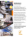
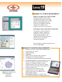
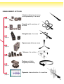
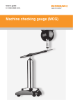
1
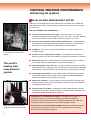
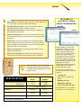
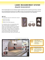
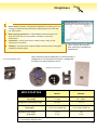
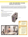
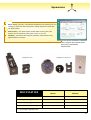
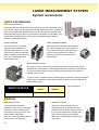
Global solutions from Renishaw
Renishaw is an established world leader in metrology, providing high performance,
cost-effective solutions for measurement and increased productivity. A worldwide
network of subsidiary companies and distributors provides exceptional service and
support for its customers.
Renishaw designs, develops and manufactures products which conform to
ISO 9001 standards.
Renishaw provides innovative solutions with the following products:
Probe systems for inspection on CMMs (co-ordinate measuring machines).
Systems for job set-up, tool setting and inspection on machine tools.
Scanning and digitising systems.
Laser and automated ballbar systems for performance measurement and
calibration of machines.
Encoder systems for high accuracy position feedback.
Spectroscopy systems for non-destructive material analysis in laboratory and
process environments.
Renishaw plc, New Mills, Wotton-under-Edge,
Gloucestershire, GL12 8JR, United Kingdom
Tel +44 (0) 1453 524524 Fax +44 (0) 1453 524901
email: [email protected]
Renishaw Inc. 5277 Trillium Blvd.,
Hoffman Estates, IL 60192, USA
Tel +1 847 843 3666 Fax +1 847 843 1744
email: [email protected]
Performance measurement systems
Renishaw K. K. Across City Nakano-Sakaue,
38-1, Chuo 1-chome, Nakano-ku, Tokyo 164-0011, Japan
Tel +81 3 5332 6021 Fax +81 3 5332 6025
email: [email protected]
Renishaw GmbH Karl-Benz Straße 12,
D 72124 Pliezhausen, Germany
Tel +49 7127 9810 Fax +49 7127 88237
email: [email protected]
Renishaw S.A. 15 rue Albert Einstein, Champs sur Marne,
77437 Marne la Vallee, Cedex 2, France
Tel +33 1 64 61 84 84 Fax +33 1 64 61 65 26
email: [email protected]
Renishaw S.p.A. Via dei Prati 5, 10044 Pianezza,
Torino, Italy
Tel +39 011 966 10 52 Fax +39 011 966 40 83
email: [email protected]
Renishaw Iberica S.A. Edificio Océano, Calle Garrotxa 10-12,
Parque Más Blau, 08820 Prat de LLobregat, Barcelona, Spain
Tel +34 93 478 21 31 Fax +34 93 478 16 08
email: [email protected]
ML10/EC10 measurement
and calibration system
Renishaw A.G. Poststrasse 5, CH 8808 Pfäffikon, Switzerland
Tel +41 55 410 66 66 Fax +41 55 410 66 69
email: [email protected]
Renishaw (Hong Kong) Ltd. Unit 4A, 3/F, New Bright Building,
11 Sheung Yuet Road, Kowloon Bay, Hong Kong
Tel +852 2753 0638 Fax +852 2756 8786
email: [email protected]
Renishaw Latino Americana Ltda. Calçada dos Crisântemos 22,
Centro Comercial de Alphaville,
C.e.p. 06453-000, Barueri-SP, Brazil
Tel +55 11 7295 2866 Fax +55 11 7295 1641
email: [email protected]
India, Bangalore
Tel +91 80 5095419 Fax +91 80 5095421
email: [email protected]
Renishaw’s Representative Offices
The Peoples’ Republic of China, Beijing
Tel +86 10 6410 7993 Fax +86 10 6410 7992
email: [email protected]
The Peoples’ Republic of China, Shanghai
Tel +86 21 6353 4897/5697 Fax +86 21 6353 4881
email: [email protected]
QC10 ballbar system
Singapore
Tel +65 8975466 Fax +65 8975467
email: [email protected]
Indonesia, Jakarta
Tel +62 21 428 70153 Fax +62 21 424 3934
email: [email protected]
Australia, Melbourne
Tel +61 3 9553 8267 Fax +61 3 9592 6738
email: [email protected]
Taiwan, Taichung City
Tel +886 4 251 3665 Fax +886 4 251 3621
email: [email protected]
Renishaw’s Liaison Office
Authorised distributor
South Korea, Seoul
Tel +82 2 565 6878 Fax +82 2 565 6879
email: [email protected]
MCG machine checking
gauge
email: [email protected]
www.renishaw.com
Corporate telephone number for Renishaw plc, New Mills:
+44 (0) 1453 524524 or 07000RENISHAW
©2000 Renishaw
Printed in England 0900 Part No. L-8003-2424-03
Measure, analyse and improve
your machines’ performance
METROLOGY IS
OUR BUSINESS
Real metrology solutions
With over 25 years of experience in the field of
engineering metrology, Renishaw has an
international reputation for producing high quality
measuring systems. From the touch trigger probe
to the complex Raman imaging microscope,
Renishaw brings real solutions to real problems.
Meeting the challenges of modern industry
The demands of modern industry to meet ever
tighter tolerances, and the requirements of
international quality standards, mean that the
performance of manufacturing machinery has
never been more important. To meet this demand,
Renishaw produces measurement systems that
assess, monitor and improve machine
performance. These systems combine the best
available mechanical, electronic and optical
technologies which have been designed for easy
use, flexibility and portability.
Systems normally reserved for research
laboratories and standards rooms can now be
used directly on the shop-floor.
The industry “standard”
Renishaw’s measurement systems are
accepted throughout the world as the
industry standard for machine
performance testing.
The world’s leading laser measurement system
The ML10 laser system represents the ultimate
in machine tool and coordinate measuring
machine (CMM) diagnostic instruments. Its
1.1 ppm accuracy provides international
traceability at a performance that other systems
just cannot match.
When you purchase a laser system from
Renishaw, you are buying the most accurate
system available. You are also buying into a
worldwide support network that understands
machine metrology, machine service and the
demands of maintaining accuracy in a
production environment.
CONTROL MACHINE
PERFORMANCE
MEASUREMENT SOFTWARE
LASER MEASUREMENT
SYSTEM
QC10 BALLBAR SYSTEM
Know the health of your machine – in 15 minutes
Machine calibration can sometimes be a time
consuming exercise. To help with this,
Renishaw’s QC10 ballbar, with its unique
diagnostic software, enables a “quick check” of
machine performance. When used with a
Zerodur® calibrator, the system provides
traceable measuring accuracy of ± 0.0015 mm
(0.00006 in).
MACHINE CHECKING GAUGE
SERVICE AND SUPPORT
The MCG gauge is the ideal way of quickly
measuring any changes in CMM volumetric
performance. Its ease of use and flexibility of
set-up makes it suitable for use on a range
of CMMs.
For useful information or
ideas on system
application, look for these
boxes throughout the
brochure.
3
CONTROL MACHINE PERFORMANCE
Introducing the systems
THE ML10 LASER MEASUREMENT SYSTEM
Used for the comprehensive accuracy assessment of machine tools, CMMs and
other positioning systems, the ML10 laser measurement system is by far the best
tool for the job.
THE FACTS SPEAK FOR THEMSELVES....
● The most accurate system of its type – system accuracy of 1.1 ppm is
maintained throughout its operating range of 0 – 40°C (32 – 104°F), a standard
level of performance that NO OTHER competitive system can match.
● Quick and safe alignments with a tripod mounted laser – all alignment can
be undertaken comfortably and safely outside the machine. No need to lose
axis travel or suffer the effects of cable drag on the measurement.
● Portability – one case, a tripod and notebook PC is all that is needed for a
Machine tool calibration of linear
axis using laser measurement
system.
complete system.
● Pioneers of error compensation software – packages that correct for linear
positioning errors of an axis are available for linking with most machine controllers.
● Ready when you are – careful design of the system means that it is ready to
The world’s
leading laser
measurement
system
use for high accuracy measurement 15 minutes after power-up.
● Optics designed for the shop user – all optics housings are made from hard
anodised aluminium, resulting in light, durable optical components that thermally
acclimatise to a shop environment 10 times quicker than steel optics housings.
● Long range measurement – linear measurements can be taken on axes up
to 80 metres (3200 inches) in length, with the option to SIMULTANEOUSLY
measure the parallel axes of dual drive machines.
● Rotary axis calibration – the combination of the ML10 laser with RX10 rotary
indexer provides the only FULLY AUTOMATIC method of rotary axis calibration
on CMMs and machine tools.
● Interferometry is traceable – all Renishaw’s laser measurements, including
straightness and angular, are interferometric, and are therefore traceable to the
international standard wavelength of laser light.
Conformance to international standards: as manufacturing industry is
constantly evolving, it is important that data is captured and assessed
according to the very latest standards. Renishaw understands this need and
continually supports its systems and users with the latest versions.
CMM space-diagonal calibration
using laser measurement system.
4
International service and technical support: Renishaw’s worldwide presence
means that users are never on their own. If you need advice or something
special, call on Renishaw’s experience.
THE QC10 BALLBAR SYSTEM
The QC10 ballbar system is a recognised standard for quickly checking CNC
machine tool performance on a regular basis.
The system is easy to set-up, simple to run and is an essential tool for all machine
shops.
● Helps to cut costs – Regular use of the QC10 ballbar results in reduced
maintenance, reduced machine downtime and reduced scrap.
● Very quick testing – 15 minutes is all that is needed to assess the
performance of your machine.
● Easy set-up – patented centring design makes set-up simple and quick.
● Simple to run – with its unique data capture and diagnostic software.
● Predict your maintenance – through regular use, it will be clear which
machines need attention, and when.
Quick and
powerful testing
● Understand changes in machine performance – the unique
diagnostic software turns the captured data into a prioritised list of ways to
improve a machine’s performance.
● Compliance to standards – ISO, ANSI, QS and ATA.
THE MACHINE CHECKING GAUGE (MCG)
● Exclusively for CMMs – for measuring repeatability and volumetric
performance.
● Compliance to standards – this measurement method complies with
BS EN ISO 10360-2.
● Flexible set-up – supplied with a range of extensions, the MCG gauge can be
adapted to test all sizes of CMM.
● Identify changing machine performance – if the volumetric numbers are
changing, so is the machine.
5
CONTROL MACHINE PERFORMANCE
Why you should measure machine performance
AS A MACHINE BUILDER YOU CAN...
IMPROVE THE PERFORMANCE OF YOUR MACHINE
Fast, accurate measurement of machine performance, quickly allows you to isolate mechanical or electrical
problems and then fix them, either by repair or by optimising machine error maps.
IMPROVE MACHINE DESIGN
A detailed analysis of machines helps to identify the impact of new design features on machining performance.
REDUCE BUILD CYCLE TIMES
By keeping a record of the performance of each machine you produce, and by closely monitoring the build
process, you gain good visibility of any production engineering problems. Machine buy-off test times can be
reduced without the need for time consuming cutting tests.
PROOF OF PERFORMANCE
Customers can be reassured that their new machines meet specification as you provide them with traceable
calibration results of machine performance before it leaves your factory. Superior portability allows you to respond
to customer requests for on-site acceptance tests.
PROVIDE A PROFESSIONAL MAINTENANCE SERVICE
High quality after-sales service is a must. Using the same calibration tools in the customer’s premises, is the best
way to restore the machine to manufactured specification.
6
AS A MACHINE USER YOU CAN...
MINIMISE SCRAP AND IMPROVE ACCURACY OF CUT PARTS
By ensuring that a machine is working to specification, the chance of scrap will be minimised. It also enables tighter
tolerances to be held on jobs and improves overall accuracy and quality.
MINIMISE MACHINE DOWNTIME
Gain a detailed picture of how each characteristic of a machine’s performance is varying over time. Predict when
maintenance work will be required for a specific machine, and establish contingency plans in advance.
WIN MACHINING CONTRACTS FROM YOUR COMPETITORS
When customers need confidence in the quality of your machining, calibration graphs and regular performance
evaluation results of your machines are excellent proof. These can give you a valuable competitive advantage over
other machining contractors, who may not perform such tests.
COMPLY WITH ISO 9000
It is a requirement of the ISO 9000 series of quality standards that manufacturing and inspection equipment is
calibrated, monitored and controlled.
GRADE THE PERFORMANCE OF ALL YOUR MACHINES
Through calibrating all your machines, you will be able to grade them according to their relative machining ability.
Assigning specific toleranced jobs to machines capable of holding these tolerances, ensures that the machine is fit
for the required purpose and less likely to produce scrap.
EXTEND THE LIFE OF YOUR MACHINE
Certain types of machine errors can lead to excessive wear in the drive system and guideways of machines. By
pinpointing and eliminating these errors at an early stage, you can improve the working life of a machine.
VALIDATE THE QUALITY OF A NEW MACHINE UPON DELIVERY
Shipping and site installation can often have a detrimental effect on a machine’s accuracy. A performance check on
the machine immediately after installation, confirms its readiness to begin work.
7
CONTROL MACHINE PERFORMANCE
How and when to calibrate and test performance
ANNUAL CALIBRATIONS
2001
Calibrations are typically performed on an
annual basis. Using the ML10 laser
measurement system to gather a
comprehensive view of all the geometric
and dynamic characteristics of a machine,
means information obtained targets any
machine maintenance that may be
required. However, machine performance
can vary significantly throughout a year,
particularly if it has crashed or been
moved. Therefore, annual calibrations
should ideally be supplemented by regular
machine performance checks.
200
0
1999
1. Perform full laser calibration
2.
Benchmark with a ballbar
● Perform a full laser
● Immediately benchmark the calibration
calibration test, measuring
all geometric, positioning
and motion characteristics
for each axis.
with the QC10 ballbar test on machine
tools, or MCG gauge test on CMMs. The
quick tests are now linked to the
comprehensive laser calibration.
INTEGRATING ANNUAL CALIBRATIONS AND
REGULAR MACHINE PERFORMANCE TESTS
The ML10 laser, QC10 ballbar and MCG gauge can be used as
complementary tools, by exploiting each of their strengths. The ML10
laser measurement system provides the ultimate accuracy and
traceability for each parameter of machine positioning and geometry. After
benchmarking a calibration, the QC10 ballbar and MCG gauge can both
provide frequent, regular snapshots of how a machine’s accuracy varies
over time and highlight when and where problems are likely to occur.
8
Week 3
X X X
X
We X X
X ek 2
X X X
X
X W
eXek
X X 1
X X X
X
X
REGULAR PERFORMANCE TESTS
The QC10 ballbar can evaluate machine tool
performance quickly and simply, with a fully automated
test procedure. In only 15 minutes, the circularity data
obtained from a test allows its powerful diagnostic
software to identify and quantify a wide variety of
errors on a machine, from machine geometry to
controller related problems.
Maintenance can then be quickly focused on the
identified problem areas, adjustments made and the
results confirmed by performing a further QC10 ballbar
test or ML10 laser measurement. Similarly, the MCG
gauge can establish a benchmark volumetric accuracy
value for CMMs from which trends can be ascertained
at regular intervals.
3.
Regularly re-check machine
● Re-check the machine with the QC10 ballbar or MCG gauge at
regular weekly or monthly intervals, or following machine relocation,
machine crash, or when parts begin to drift from tolerance.
4. Pinpoint problem areas
Regular pre-planned checks enable a machine’s performance to be
charted over time and future accuracy problems to be intelligently
predicted through trend analysis.
5.
Repair and re-calibrate with a laser
● After maintenance work, the
machine can be re-calibrated using
the ML10 laser measurement
system.
● If overall machine accuracy falls
below an acceptable level, use the
QC10 diagnostic software to analyse
and pinpoint problem areas, and for
advice on appropriate maintenance
work. On CMMs, it is advisable to
perform a laser test to identify the
specific location of an error.
9
MEASUREMENT SOFTWARE
SOFTWARE DESIGNED WITH THE USER IN MIND
Laser and ballbar
measurement software is
supplied on CD-ROM in
a multilingual format for
a range of languages.
The user interface to both the ML10 laser and QC10 ballbar uses
dedicated Windows ® 95, 98, NT4, 2000 or ME compatible software exclusively
developed by Renishaw.
The ML10 laser software provides the capability for both static and dynamic
measurement of a machine’s linear, angular, straightness, squareness and
rotary accuracy. It is supplied with dynamic, dual axis, digital indicator, electronic
level, universal error compensation and on-line help capability as standard.
FLEXIBILITY OF DATA COLLECTION
To meet the requirements of different applications, the laser software employs
an array of automatic and
manual data capture methods:
Manual:
Keyboard, remote hand
switch.
Automatic:
Time and position based,
dynamic, encoder triggered
(via the TB10 trigger box).
Simultaneous dual
measurement
DATA ANALYSIS TO INTERNATIONAL STANDARDS
Data can be collected from
two axes simultaneously and
then analysed independently.
10
Laser data analysed to the
following standards:
ISO 230-2
ANSI B5.54
ANSI B89
VDI 3441
VDI 2617
JIS-B6330
GB-10931-89
Operating within the Windows environment, data can be exported
into other applications in raw format. Alternatively, analysed data can
be cut and pasted into other applications, thus enabling professional
presentation of test results.
LINKING TO OTHER INSTRUMENTS
HEWLETT PACKARD 5528 LASER SYSTEMS
Renishaw’s software can be used as
the interface for existing users of 5528
Hewlett Packard systems, when coupled
with one of our GPIB interface kits.
These kits are available in either ISA
card format for desktop PCs or
PCMCIA card format for notebook PCs.
ELECTRONIC LEVELS AND DIGITAL INDICATORS
The software is extremely flexible in
enabling the capture, storage and
presentation of data from electronic
levels and digital indicators. The
captured data can then be analysed in
accordance with national and
international standards.
More information on system interfacing can be
found on pages 32-33
MINIMUM COMPUTER REQUIREMENTS
Ballbar data analysed to the
following standards:
ISO 230-4
ANSI B5.54
●
●
●
●
●
●
●
●
Windows® 95, 98, NT4, 2000 or ME operating system,
●
An RS232 port will be required if using
accessories such as error compensation
software, RX10 rotary axis calibrator or the
digital indicator interface.
●
For the ballbar system. The computer must
have at least one RS232 port available (9600 Baud).
Internet Explorer 5 or later,
200MHz processor,
32MB RAM,
Minimum Screen resolution 800 x 600 pixels,
CD-ROM drive for software installation,
3.5” floppy drive (optional for data storage and transfer),
For the laser system. If a PCM10 interface card is to
be used, a single Type II PCMCIA card bus slot is
required on a notebook computer. If a PC10
computer interface card is to be used, the desktop
computer must have one spare 8-bit half length ISA
slot for the interface card.
11
LASER MEASUREMENT SYSTEM
System architecture
The Renishaw laser measurement system is an ideal solution for complete calibration of machines, enabling the
measurement of a wide range of geometric and dynamic characteristics. It employs a flexible, modular system
architecture ensuring that it can best fit your specific measuring requirements, and grow as they grow.
EC10 COMPENSATION UNIT
ML10 LASER HEAD
At the heart of the system are the
ML10 laser head and EC10
environmental compensation unit.
These core components together
represent the most accurate laser
measurement system available to
industry with 1.1 ppm accuracy
maintained over the
FULL operational temperature range
of 0-40 °C (32-104 °F).
page 14
page 15
page 32
page 32
page 32
PCM10 INTERFACE CARD
PC10 INTERFACE CARD
ISA SLOT
LX10 INTERFACE UNIT
NOTEBOOK PC
DESKTOP PC
RS232/IEEE
– HP5528 LASER SYSTEM
– 3RD PARTY ELECTRONIC LEVELS
AND DIGITAL INDICATORS
12
PCMCIA
SLOT
page 32, 33
MEASUREMENT OPTIONS
Linear positioning accuracy
and repeatability of an axis
page 16
Angular pitch and yaw of
an axis
page 18
Straightness of an axis
page 20
Squareness between axes
page 22
Flatness of a surface
page 24
Rotary axis/table
angular positioning
page 26
Dynamic characteristics of a machine
page 28
13
LASER MEASUREMENT SYSTEM
The laser and environmental compensation
THE ML10 LASER HEAD
The ML10 laser head is the core unit of the measurement system. It contains a Helium Neon (HeNe) laser tube producing
stabilised laser light at 633nm. The Class II laser power rating means that it can be used without the need for special
safety equipment. The single frequency laser contains sophisticated electronics for stabilisation and to interpolate and
count the interference fringes. This provides true nanometre resolution measurements at feedrates in excess of
1 m/s (40 in/s). Renishaw’s ML10 system can be used for calibrating axes up to 80 m (3200 in) in length.
The ML10 laser wavelength is traceable to internationally recognised length standards. Traceability of every laser is
ensured via Renishaw’s in-house iodine stabilised reference laser, which in turn is referenced to the UK’s National Physical
Laboratory (NPL) iodine stabilised
reference laser. This provides a
recognised association to the network
Laser system accuracy is
of national standards organisations
such as:
1.1 ppm over FULL
NIST (US)
IGMC (Italy)
NPL (India)
NRLM (Japan)
NIM (China)
PTB (Germany)
LNE or CTA (France)
environmental range
Laser wavelength accuracy
Air refraction compensation accuracy
Renishaw’s system accuracy
Typical competitors system accuracy
SPECIFICATION
Renishaw’s material expansion
normalisation accuracy
Laser source
Helium Neon (HeNe) laser tube (CLASS II)
Laser power
<1 mW
Typical competitor’s material expansion
normalisation accuracy
632.9906 nm (nominal)
*Comparative system accuracy
Long term frequency accuracy
± 0.1 ppm (parts per million)
-including normalisation for
material expansion
Outputs
RS485 from 5 pin ‘Datalink’
Power supply
Operating temperature
Operating humidity
Weight
Dimensions
Units for power supplies
of 100-240 volts
Frequency tolerance: 45-65 Hz
0 – 40 oC (32 – 104 oF)
6
Accuracy (± µm / m)
Vacuum wavelength
5
4
2
0 – 95% non condensing
1
Max weight 5.3 kg (11.7 lb)
0
335 x 176 x 75 mm (13.2 x 6.9 x 2.95 in)
Typical competitive laser systems
do not hold accuracy over the
FULL environmental range
3
ML10 laser system – consistent
accuracy over FULL
environmental range
0
(32)
10
(50)
20
(68)
30
(86)
Environmental temperature oC ( oF)
14
*Based on material with thermal expansion co-efficient of 10 ppm /
o
C
THE EC10 COMPENSATION UNIT
The accuracy of a laser distance measurement system is primarily dependant on how well it can compensate for the
effects of air refraction changes on the wavelength of the laser. Without this compensation, accuracy of any system is
significantly compromised. Recognising this fact, Renishaw has designed its environmental compensation unit (EC10) to
be extremely accurate.
The EC10 compensation unit continually monitors the surrounding environment by collecting data from highly accurate
sensors measuring the ambient air temperature, pressure and humidity. From this data, the unit calculates the true laser
wavelength using Edlen’s equation. This compensated wavelength is combined with the fringe count from the ML10 laser
to give compensated distance measurements with guaranteed accuracy.
In order to compensate for machine thermal expansion, the EC10 unit can
also receive data from up to three material temperature sensors which can
be placed in strategic positions on the machine under test. This
normalises all readings to a reference temperature of 20 oC (68 oF).
Thermal compensation is particularly important when performing linear
measurements especially on large machines or machines made of
high expansion materials.
The EC10 compensation
unit can also be used as a
stand-alone environmental
‘chart’ recorder.
= ± 0.1 ppm
= ± 1.0 ppm
= ± 1.1 ppm
= up to ± 3.0 ppm
= ± 1.0 ppm*
= ± 3.0 ppm*
SPECIFICATION
METRIC
IMPERIAL
Air temperature range
0 – 40 oC
32 – 104 oF
Air temperature accuracy
± 0.5 oC
± 0.9 oF
750 – 1150 mbar
22.43 – 34.40 in Hg
± 2.2 mbar
± 0.06 in Hg
Air pressure range
Air pressure accuracy
Relative humidity range
Relative humidity accuracy
0.000060
Wavelength compensation accuracy
0.000048
0.000036
0.000024
0.000012
0
40
(104)
Accuracy (± inches / ft)
0.000072
0 – 95% (non condensing)
20% RH
± 1.0 ppm (parts per million)
Material temperature range
0 – 40 oC
32 – 104 oF
Material temperature accuracy
± 0.1 oC
± 0.18 oF
Power supply
Weight
Dimensions
Specific units for power supplies of 100, 110, 220, 240 volts
Voltage tolerance: ± 20%
Frequency tolerance: 45-65 Hz
4.0 kg
8.8 lb
335 x 176 x 75 mm
13.2 x 6.9 x 2.95 in
15
LASER MEASUREMENT SYSTEM
Linear measurement
This is the most common form of measurement performed on machines. The system measures linear positioning
accuracy and repeatability by comparing the position displayed on a machine’s readout with the true position
measured by the laser. These values can then be viewed, printed and statistically analysed by the system
software to national and international standards. On many of today’s machine tools, it is also possible to take this
process one step further and automatically download the measured data to a compensation table in the machine’s
controller. In this way, a machine’s positioning accuracy can be verified and significantly improved quickly and
easily.
Linear optics
SET-UP
The components used in this measurement comprise:
Linear beam-splitter
Retro-reflectors
Targets (for easy optical alignment)
In linear measurement, one retro-reflector is secured to the beam-splitter, to
form the fixed length reference arm of the interferometer. The other retroreflector moves relative to the beam-splitter and forms the variable length
measurement arm. The laser system tracks any change in the separation
between the measurement arm retro-reflector and beam-splitter.
To mount the optics on a machine, a range of accessories and fixtures is
available. There are additional accessories which can be supplied to help
measurement set-up and data capture. These are described on the system
accessories section on page 30.
X axis linear positioning measurement on a VMC
Long range retro-reflector and periscope
When measuring axes of lengths
above 40 metres, the long range
version of the laser head, ML10X,
and patented long range linear optics
are required.
For measurement of dual
or tandem drive machines,
connect two laser systems
together with the
DUAL AXIS SOFTWARE.
Refer to page 32.
16
Linear
●
Highly durable – the aluminium optics housings, including threads, are
all hard-anodised, corrosion proof and shock resistant.
●
THE POWER OF
AUTOMATIC LINEAR
ERROR COMPENSATION
BEFORE
Improved dynamic response – with less than half the weight of
steel optics housings, machine loading is reduced.
●
AFTER
Quick thermal acclimatisation – aluminium optics acclimatise 10
times quicker than steel optics.
●
No thermal drift problems – the interferometer is remote from the
heat of the laser head, with the laser heat source remaining outside
the machine.
●
Easier set-up – the remote interferometer can be fitted to specific
areas of interest on a machine, without loss of axis travel. This also
allows for multiple axis measurements to be made from one position,
without the need to re-align the laser.
●
External laser alignment – tripod mounted laser makes for easy
alignment outside machine.
●
Easier long-range alignment – the larger retro-reflector gives an
easy target to hit and returns more laser light, even in turbulent air.
The unique design of linear, angular and
straightness optics enables easy interchange
for different measurements without having to
re-align the laser.
With the addition of a linear error
compensation package, the data
obtained from a calibration cycle is
used to calculate compensation
values, which can then be fed into a
machine’s controller. Once the
compensation has been completed,
a final laser check ensures that a
machine’s positioning accuracy has
been significantly improved. These
packages now include a
compensation “wizard” and session
progress indicator to make axis
compensation even easier.
The software can interface with
many of today’s machine controllers
including:
Fanuc 0M, 0T.
SPECIFICATION
METRIC
IMPERIAL
Linear measurement (standard range)
0 – 40 m
0 – 1600 in
0 – 80 m
0 – 3200 in
Fanuc 10, 11, 12, 15, 16, 18,
20, 21.
NUM 750, 760, 1060.
(long range)
Mazak M-Plus, M2, M32
Siemens 810, 840C, 850, 880
Accuracy (with EC10 compensator)
± 1.1 ppm (parts per million)
Resolution
0.001 µm
0.1 µin
Maximum velocity
60 m/min
(1 m/s)
2400 in/min
(40 in/sec)
Velocity measurement accuracy
Contact Renishaw if your required
controller is not on the above list.
± 0.05%
% = percentage of displayed value
17
LASER MEASUREMENT SYSTEM
Angular measurement
Pitch and yaw angular errors are among the largest contributory factors to positioning inaccuracy in machine
tools and measurement accuracy errors on CMMs. Yaw errors can be caused by a machine moving unevenly
along slack guideways, whereas pitch errors can be caused by bowing effects in these guideways.
SET-UP
The components used in this measurement comprise:
Angular beam-splitter
Angular retro-reflector
Angular optics
Targets (for easy optical alignment)
For measurement set-up, the angular beam-splitter
optic is best mounted in a fixed position on a
machine, for example, the spindle on a moving bed
machine tool or granite table on a CMM. The retroreflector optic is then mounted to the moving part of
the machine, for example, the bed of a machine tool
or probe-head of a CMM. The measurements are
made by monitoring the change in relative angle
between the beam-splitter optic and the reflector optic.
X axis pitch measurement on a moving bed VMC
Angular optics can also be
used to measure the
flatness of CMM table and
surface plates.
Refer to page 24.
Rotary axes can also be
calibrated using angular
optics in combination with
the RX10 rotary indexer.
Refer to page 26.
18
Angular
●
Highly durable – aluminium optics housings, including threads, are all hardanodised, corrosion proof and shock resistant.
●
Reduced machine loading – with less than half the weight of steel optics,
machine loading is reduced. This is especially relevant if measuring pitch errors
on horizontal arm CMMs.
●
Quick thermal acclimatisation – aluminium optics housings acclimatise
10 times quicker than those made from steel.
●
No thermal drift problems – the interferometer is remote from the heat of the
laser head, with the laser heat source remaining outside the machine.
●
Traceability – interferometry directly benefits from the traceability of the laser
This is a typical plot captured
when performing an angular
measurement.
wavelength. PSD/CCD/Quad cell based systems do not.
●
Accuracy – interferometry offers more accuracy and linearity with less sensitivity
to air turbulence noise, compared to PSD/CCD/Quad cell based systems.
●
For single set-up of
both linear and
angular
measurements,
contact us to find out
more about our
special optics
combination kits.
Easier set-up – the remote interferometer can be fitted to specific areas of
interest on a machine, without loss of axis travel. This also allows for multiple
axis measurements to be made from one position, without the need to re-align
the laser.
●
Convenience – moving optics have no cables to drag or snag, for best
accuracy and convenience.
●
Flexibility – the software also supports angular measurements using
electronic levels.
SPECIFICATION
Axial range
Angular measurement range
Angular accuracy
Resolution
METRIC
IMPERIAL
0 – 15 m
0 – 590 in
± 175 mm/m
± 10o
± 0.6%* ± 0.5 ± 0.1M µm/m
± 0.6%* ± 0.1 ± 0.007F arc sec
0.1 µm/m
0.01 arc sec
Where M = measurement distance in metres; F = measurement distance in feet
% = percentage of calculated angle
* Higher accuracy angular optics of ± 0.2% and better can be supplied to special order
19
LASER MEASUREMENT SYSTEM
Straightness measurement
Straightness measurements highlight any bending component or overall misalignment in the guideways of a
machine. This could be the result of wear in these guideways, an accident which may have damaged them in
some way, or poor machine foundations that are causing a bowing effect on the whole machine. This straightness
error will have a direct effect on the positioning and contouring accuracy of a machine.
SET-UP
The components used in this measurement
comprise:
Short range straightness optics
Straightness beam-splitter
Straightness retro-reflector
For measurement set-up, the straightness
reflector must be mounted to a fixed position
on a machine. The straightness beam-splitter
should then be mounted to the moving part of
the machine. There are two kits available for
measuring both shorter axes (0.1 – 4.0 m)
and longer axes (1 – 30 m).
X axis straightness measurement on a moving bed VMC
If straightness
measurements are taken on
two axes, it is possible to
assess parallelism. It is also
possible to measure
squareness errors between
these axes.
Refer to page 22.
20
Straightness
●
Easier set-up – geometry of the patented straightness retro-reflector gives nonoverlapping output and return laser beams, making alignment far easier than
with other systems.
●
Best long-range performance – PSD/CCD/Quad cell based systems can
suffer from noise and accuracy problems, particularly on long range
measurement.
●
Convenience – moving optics have no cables to drag or snag, for best
accuracy and convenience.
●
Flexibility – the software also supports straightness measurements using digital
indicators and straight edges.
Long range straightness optics
This is a typical plot captured
when performing a straightness
measurement.
When measuring vertical straightness in a horizontal axis, or
straightness in a vertical axis of a machine, a straightness
accessory kit is also required for set-up.
Straightness accessory kit
SPECIFICATION
Axial range (short range)
(long range)
Straightness measurement range
Accuracy (short range)
(long range)
Resolution (short range)
(long range)
METRIC
IMPERIAL
0.1 – 4.0 m
1 – 30 m
4 – 160 in
40 – 1200 in
± 2.5 mm
± 0.1 in
± 0.5% ± 0.5 ± 0.15M2 µm
± 0.5% ± 20 ± 0.5F2 µin
± 2.5% ± 5 ± 0.015M2 µm
± 2.5% ± 200 ± 0.05F2 µin
0.01 µm
1 µin
0.1 µm
10 µin
Where M = measurement distance in metres; F = measurement distance in feet
% = percentage of displayed value
21
LASER MEASUREMENT SYSTEM
Squareness measurement
Squareness measurement determines the out-of-squareness of two nominally orthogonal axes, by comparing
their straightness values. Squareness errors could be the result of wear in machine guideways, an accident which
may have caused damage, poor machine foundations or misaligned home position sensors on gantry machines.
This squareness error will have a direct effect on the positioning accuracy and contouring ability of a machine.
SET-UP
The specific component required for this measurement is:
Optical square + bracket.
In addition to the optical square, straightness optics
and a straightness accessory kit are also required
for set-up (see opposite). Other set-up
accessories may also be required, depending
on what axes are being measured and the
configuration of the machine.
Optical square
As a quick alternative for
measuring squareness on
machine tools, why not
use the QC10 ballbar?
X-Z axis squareness measurement on a VMC
Refer to page 34.
On smaller machines, the
limited working volume
can make laser squareness
measurement inconvenient.
Instead, why not use a
granite square and connect
a digital indicator to the
Renishaw squareness
measurement software?
Refer to page 33.
22
Squareness
●
Easier set-up – geometry of the patented straightness retro-reflector gives nonoverlapping output and return laser beams, making alignment far easier than
with other systems.
●
Best accuracy – the optical square provides better accuracy than other
systems due to the premium grade optics used (± 0.5 arc sec).
●
Flexibility – the software also supports squareness measurements using
digital indicators and square.
This is a typical plot captured when
performing a squareness
measurement.
Straightness optics
SPECIFICATION
Range
Accuracy (short range)
(long range)
Resolution
Straightness accessory kit
METRIC
IMPERIAL
± 3/M mm/m
± 2000/F arc sec
± 0.5% ± 2.5 ± 0.8M µm/m
± 0.5% ± 0.5 ± 0.05F arc sec
± 2.5% ± 2.5 ± 0.08M µm/m
± 2.5% ± 0.5 ± 0.005F arc sec
0.01 µm/m
0.01 arc sec
Where M = measurement distance in metres of the longest axis; F = measurement distance in feet
% = percentage of displayed value
23
LASER MEASUREMENT SYSTEM
Flatness measurement
This measurement is performed to check the accuracy of CMM tables and all types of surface plate. It determines
whether any significant peaks or troughs exist and, in turn, quantifies them. If these errors are significant to the
application of the flat surface, then remedial work, such as further lapping, may be required.
SET-UP
The specific components used in this measurement comprise:
Base (50mm)
Flatness mirrors and bases
Base (100mm)
Base (150mm)
Flatness mirrors
Angular optics
Angular measurement optics are also required to
attach on top of the flatness bases. These are available
separately and are shown in the angular measurement
section. Refer to page 18.
The angular retro-reflector is mounted on one of three
lengths of flatness foot-spacing base. The size of base
used depends on the size of surface to be tested and
the required number of points to be taken. The angular
beam-splitter is mounted on the flatness mirror base.
If you currently use FEDERAL PRODUCT’S
electronic levels for flatness measurement, why
not connect to the Renishaw flatness
measurement software? Refer to page 33.
24
Flatness
●
No thermal drift problems – the interferometer is remote from the warmth of
the laser head.
●
Traceability – interferometry directly benefits from the accuracy and traceability
of the laser wavelength. PSD/CCD/Quad cell based systems do not.
●
Easier set-up – the flatness mirrors are non-slip and fully adjustable for both
pitch and yaw for simple, quick alignment.
●
Flexibility – the software supports flatness measurement using electronic
levels. It can also support both Grid and Moody plot techniques.
●
Single laser positioning – all measurement lines can be achieved from a
single laser position.
Before making any measurements, a ‘map’ of
the measurement lines should be marked out on
the surface. The length of each line should be
an integral multiple of the foot-spacing base
selected. There are two standard methods of
conducting flatness measurements:
These are the typical plots obtained from
a flatness measurement. The top graph
shows a Moody plot type whilst the
bottom shows a typical Grid plot type.
a) Moody method – in which measurement is
restricted to eight prescribed lines.
b) Grid method – in which any number of lines
may be taken in two orthogonal directions
across the surface.
SPECIFICATION
METRIC
IMPERIAL
Axial range
0 – 15 m
0 – 590 in
Flatness measurement range
± 1.5 mm
± 0.06 in
± 0.6%* ± 0.02M2 µm
± 0.6%* ± 0.08F2 µin
0.01 µm
1 µin
Accuracy
Resolution
Where M = length of the diagonal in metres; F = length of the diagonal in feet
% = percentage of calculated flatness
* Higher accuracy angular optics of ± 0.2% and better can be supplied to special order
25
LASER MEASUREMENT SYSTEM
Rotary measurement
On many machines, it is often forgotten how the accuracy of a rotary axis is important to overall system accuracy.
This could be the rotary axes on 4 and 5 axis machine tools or the rotary table on a CMM. In line with the
fundamental importance of rotary axis accuracy, recent national and international standards have made strong
provision for their measurement. It is for this reason that Renishaw has developed a specific rotary axis
calibration system, the RX10, to be used in conjunction with its laser system.
The patented method of calibration has revolutionised measurement of rotary axes. Automated testing now
enables rotary axes to be checked in just 25 minutes and at any angular position. This represents a massive time
saving of more than 5 hours over traditional methods such as auto-collimators and optical polygons.
RX10 rotary
indexer
SET-UP
The components used in this measurement comprise:
RX10 rotary indexer
RX10 controller/power supply
Angular measurement optics are also
required to attach to the top of the
indexer. These are available
separately and are shown in the angular
measurement section. Refer to page 18.
The RX10 features an extremely accurate Hirth-coupling design that guarantees
quality and reliability of the indexer along with the accuracy of the laser. With its
built-in calibration routine, centring and other set-up inaccuracies are easily
eliminated. The system will operate horizontally, vertically or even upside-down
for easy calibration of different orientations of rotary axis.
RS232 CONNECTION
TO PC
Controller
/power supply
To automatically calibrate
rotary tables or axes that
lift before rotating, ask
about our Lifting Table
Accessory Kit.
26
Rotary
BEFORE
●
Easier set-up – the indexer performs an automated calibration
routine to eliminate set-up errors, therefore there is no need to
accurately centre the system.
●
Quick, automated calibration – the indexer is motorised for lock,
unlock and rotate movements to enable automatic alignment and
tracking without any operator or machine intervention (ideal for CMMs).
●
Flexibility – can calibrate any angle with accuracy, even multiple
revolutions.
AFTER
A rotary axis can be calibrated through five easy steps:
1 Attach a standard angular retro-reflector to the RX10 rotary indexer.
2 Attach the RX10 rotary indexer to the axis under test by clamping
the mounting plate to the table.
3 Attach the angular beam-splitter optic to a stable independent mounting.
4 The rotary axis is calibrated by rotating it sequentially through a
number of angular targets as pre-selected in Renishaw’s
calibration software. Laser readings are taken at each position.
5 As the axis rotates, the RX10 rotary indexer is counter-rotated
automatically to ensure that the laser beam is returned back to the laser.
Recent international standards
state that a rotary axis should be
calibrated in a number of ways,
which include:
SPECIFICATION
The two graphs show errors in a rotary
axis both before calibration and after
repair work has been carried out.
METRIC
Angular range
Indexing accuracy
IMPERIAL
unlimited
± 5 µm/m
± 1 arc sec
0.2 arc sec
0.1o increments through 5o.
Repeatability
1 µm/m
3o intervals through 360o .
Mounting
Top or bottom faces for spindle
or table location
Operation
Vertical or horizontal
o
o
o
o
At 0 , 90 , 180 and 270 positions
and nine further random angular
positions through 360o. It is
extremely difficult, if not
impossible, to complete these
measurements using autocollimators and optical polygons.
Control
Operating temperature
Max velocity of indexer table
Automatic via RS232 to PC
0 – 40 oC
32 – 104 oF
30rpm when the measurement step size is
less than 10 degrees
2rpm when measurement step size is
more than 10 degrees
27
LASER MEASUREMENT SYSTEM
Dynamic measurement
The dynamic measurement capability of Renishaw’s laser system adds a new dimension of flexibility and power. It
enables real-time measurement of motion characteristics of machines’ systems to be made in addition to the
traditional static tests described earlier in this section. Only specialised equipment can normally pinpoint such
characteristics. This greatly extends the capability of the laser system and makes it an essential tool in machine
CONDITION MONITORING programmes.
This software can be used to evaluate acceleration, vibration, velocity and servo control performance. This is extremely
useful for assessing the performance of many different types of machines used in industry, not just CMMs and machine
tools. Other machines that benefit from the system include:
Robotic pick and place machines
Surface mount machines
Hydraulic and pneumatic systems
Reciprocating and positioning systems
Optical stages
Printing presses
Dynamic software
PCB drilling/routing machines
PCB printing machines
This measurement capability is supplied as part of the standard laser software package and requires no additional
hardware other than the optics for the specific measurement being performed.
These real-time measurements allow
certain machine error characteristics
to be highlighted and quantified. For
example:
Pre-load and hysteresis of
ballscrew and nut mechanisms
Positional stability and encoder
performance
Resonance characterisation of drive
motors, spindles and other systems
Feedrate accuracy, stability and
interpolation accuracy
Control-loop optimisation
28
Dynamic
Vibration analysis
●
Powerful vibration analysis – integrated FFT (Fast Fourier Transform)
routines give a detailed frequency spectrum enabling identification of
vibrations and the pinpointing of their source.
●
Optics versatility – the software supports dynamic data capture and
analysis using linear, angular or straightness optics.
●
High capability – using a single frequency laser system provides true
nanometre resolution at feedrates up to 1 m/s with 5000 Hz sample rate
and no acceleration limit.
●
Flexibility – data can be taken in response to internal timebases, or in
synchronisation with external triggers at rates up to 4000 Hz.
Using the dynamic measuring capability,
the following measurements can be
performed:
FFT frequency analysis
Displacement against time
Velocity against time
Acceleration against time
Vibration amplitude and frequency
Used in conjunction with
the TB10 trigger box,
dynamic software is ideal for
Displacement against time
Velocity against time
inspecting ballscrew
assemblies. Refer to page 31.
Acceleration against time
SPECIFICATION
METRIC
Sampling rates
Linear displacement accuracy
IMPERIAL
10 – 5000 Hz
± 1.1 ppm (parts per million)
Linear velocity accuracy
± 0.01%
Linear acceleration accuracy
± 0.01%
Time accuracy
± 0.14%
Resolution
0.001 µm
0.04 µin
Servo response analysis
% = percentage of displayed value
29
LASER MEASUREMENT SYSTEM
System accessories
OPTICS ACCESSORIES
OPTICS MOUNTING KIT
This kit provides the essential elements required to mount the Renishaw optics
to a machine. Optics can be easily interchanged without the need to re-align the
laser. It comes with hard anodised aluminium mounting blocks, stainless steel
pillars and bases for the optimum combination of portability and durability. They
also incorporate M8 threads for attachment to standard magnetic bases or
Renishaw’s CMM probe heads.
SWIVEL MIRROR
FIXED TURNING MIRROR
This mirror can be used as an
alignment aid for ANSI B5.54
diagonal measurements. It is also
useful when measuring slant-bed
lathes. Clamping screws allow the
mirror to be easily attached to
measurement optics.
This mirror reflects the laser beam through
90o. Like the swivel mirror, it can attach to
the measurement optics to aid optical setup and is used primarily when there is
restricted access to the required axis of
measurement.
BEAM STEERER LS350
This unique* optic provides easy angular adjustment of the laser beam in both
horizontal and vertical planes, making laser alignment a simple one step process.
The beam steerer speeds up linear, angular and straightness measurements,
whether in-line or at 90°.
The optic is also compatible with the linear/angular combination kit and swivel/fixed
turning mirrors. Clamping screws allow the beam steerer to be easily attached to
measurement optics.
*Patent applied for.
SPECIFICATION
Steering range
METRIC
IMPERIAL
+/-35mm/m
+/-2° (imperial)
TRIPODS
STANDARD TRIPOD
COMPACT TRIPOD
This tripod offers the widest
adjustment range for the mounting of
the laser. It can be supplied with a
hard-wearing carrying case for safe
transportation and storage.
(Note: the mounting stage is stored in
the supercase, not this case).
This tripod’s major benefits over the
standard tripod is its reduced size when
collapsed, and its smaller carrying case. It
too can be supplied with a carrying case,
which is both rugged and lightweight.
(Note: the mounting stage is stored in the
supercase).
30
CASES
Portability of laser measurement systems is extremely important. This is especially true for
mobile calibration companies or organisations based in a number of different geographical
locations. Renishaw’s laser system has been designed with this in mind and comes with a
range of carrying cases to complement the size of system.
SUPERCASE KIT
This case is capable of housing the comprehensive range of optics and
equipment of the laser system. This includes ML10 laser head, EC10
compensation unit and all optics kits, sensors, cables and the tripod stage. It is
extremely durable, with built-in dust and pressure seals, giving the best
protection to the system. It comes with an accompanying cart, which attaches
directly to the case, and padlock for added security. The compact tripod can be
attached to the case and cart to provide easy portability of the complete system.
SMALL CARRYING CASE
LARGE CARRYING CASE
OPTICS CARRYING CASE
This case is designed to hold either
an ML10 laser head or EC10
compensation unit along with
environmental sensors.
This case can house an ML10 laser
head, EC10 compensation unit and
sensors, cables, linear optics,
angular optics and flatness kit.
This carrying case can hold the
straightness and squareness optics
and their associated accessories.
DATA CAPTURE ACCESSORIES
HAND HELD SWITCH
This enables remote datuming of the laser and manual data capture. It is ideal in applications
where the machine’s controller is far from the point of test. It has a built-in safety feature to
prevent accidental datuming and comes with 10 metres of cable which may be extended in
5 metre increments, if necessary.
TB10 QUADRATURE TRIGGER BOX
This device monitors the position feedback signals between a machine’s encoders and its
controller and feeds trigger signals to the Renishaw laser system. This allows synchronisation of
data capture from the ML10 laser head to scale position or movement.
It is primarily used in applications such as ‘on-the-fly data capture’ or for monitoring scale errors,
so a machine can be driven along an axis without stopping to collect data for position, angle,
straightness etc. This mains-powered unit works with TTL quadrature or analogue current loop
encoders and triggers the laser measurement at regular user-defined intervals.
31
LASER MEASUREMENT SYSTEM
System interfacing
LASER INTERFACES
PCM10 – INTERFACING WITH NOTEBOOK PCs
To maximise portability and performance, Renishaw has developed its own
PCMCIA (PCCARD type II) interface to connect its laser system to notebook
PCs. Whilst other systems rely on full length ISA bus cards, or slower RS232
ports which limit performance, Renishaw’s PCM10 interface supports a
1 Mbit/sec link allowing data capture at 5000 readings/sec, at feedrates of
1 m/sec, whilst still maintaining true nanometre resolution.
There is no need to use a bulky desktop PC or docking station with the
Renishaw PCM10 interface.
PC10 – INTERFACING WITH DESKTOP PCs
GPIB – INTERFACING TO AN HP5528 SYSTEM
The PC10 card provides an identical level of performance
as the PCM10 interface and is used when connecting to
a desktop PC or docking station with ISA slots. The PC10
card is supplied as a half length ISA card.
For users of the HP5528 system who prefer
Renishaw’s calibration software, choose
between the GPIB/ISA card or GPIB/PCMCIA
card formats to suit your computer.*
LX10 – FOR INTERFACING WITH CUSTOM SOFTWARE
The LX10 interface provides all the benefits of the ML10 laser system hardware
without having to modify existing software*. The unit can be switched to emulate
the HP5528 with no loss of resolution or accuracy.
It also enables the ML10
system to interface with PCs
with no expansion card or
PCMCIA facilities, by using
the PC’s RS232 port.
Trigger pulse
input/output
ML10 laser
Existing calibration or
diagnostic software
RS232/IEEE
* Not compatible for
dynamic measurement.
LYNX
EC10
DUAL AXIS CALIBRATION
A. Laser
B. Interferometer
C. Retroreflector
D. Material temperature
and environmental pick-ups
In some installations, one axis is controlled by two drives and two
feedback systems (eg “SPAR MILL” and large dual beam type
CMMs). In this instance, a second interface card, coupled with
dual axis software, provides the capability to automatically
capture data of parallel axes simultaneously.
Dual-axis measurement
software is provided as
part of the standard laser
software package.
C
C
B
D
A
D
B
A
32
PC
INSTRUMENT INTERFACES
Instrument interfaces give you the capability of displaying, recording and analysing your data, using Renishaw’s calibration
software.
● Access Renishaw’s powerful suite of software for angle,
straightness and flatness data capture when using
electronic levels or digital indicators.
● Analyse data to national and international standards.
● Offers a consistent user interface.
● Single location for data storage, retrieval and back-up.
● Increase your choice of measurement instruments,
● Unified presentation of calibration graphs, whatever the
allowing your preferred method to be assigned to
each measurement.
measurement technique.
DIGITAL INDICATOR INTERFACE
This interface accepts data from both the FEDERAL PRODUCT’S µMAXµM and
MITUTOYO’S DIGIMATIC digital indicators. Output data from the indicator
through a specially developed interface, is automatically converted into a format
which can be used by Renishaw’s calibration software. The kit is easy to install
and comprises: electrical interface, serial port adaptor cable, software and
manual.*
What can you measure?
Axis straightness – using digital indicator and straight edge.
Axes squareness – using digital indicator and square.
Axis roll – using two digital indicators, straight edge and dual axis software.
Linear repeatability, backlash and drift tests – using digital indicator.
FEDERAL PRODUCTS 832 AMPLIFIER INTERFACE
This interface accepts data from a FEDERAL PRODUCT’S 832 SERIES
amplifier and its associated electronic levels and gauges. Output data from the
amplifier is transferred directly to Renishaw’s calibration software via the serial
port of a PC and special translation software. The kit comprises: serial port
adaptor cable, software and user manual.*
What can you measure?
Axis straightness – using electronic gauge and straight edge.
Axes squareness – using electronic gauge and square.
Horizontal axis pitch and roll – using electronic levels.
Vertical axis pitch and yaw – using electronic levels.
Vertical axis roll – using twin electronic gauges and straight edge.
Surface flatness – using electronic levels.
*Note: These interfaces do not include any third-party instruments or Renishaw’s calibration software which can be
purchased separately.
33
QC10 BALLBAR SYSTEM
THE QUICK CHECK WITH POWERFUL RESULTS
1.
Set-up
The QC10 ballbar is regarded by many machine users around the world as
the revolutionary solution to REGULAR machine performance testing.
● Verify machine performance
● Achieve manufacturing tolerances
● Grade/compare machines
● Condition monitoring
Set-up is quick and easy.
● New machine acceptance testing
The QC10 ballbar is mounted
between two repeatable magnetic
joints.
● Predictive maintenance
A simple G02 and G03 command
program is required for the test.
BALLBAR ACCESSORIES
The 360° lathe adaptor enables the
ballbar to be used on larger CNC
lathes and allows a full automatic
diagnosis.
Using the
supplied
extension bars,
the ballbar can
perform a wide
selection of
tests ranging
from 100mm to
600mm in
radius.
To address smaller machines, the
small circle accessory kit allows
testing of CNC machines with shorter
axis travel. Additionally, it gives an
enhanced analysis of servo control
systems on most types of
machines.
For 2-axis
CNC
machine
applications,
a special
retractable
centre
mount, the VTL adaptor, is
used. This enables typical
2-axis machines such as pick
and place machines, laser
cutting machines and vertical
turning lathes etc. to benefit
from ballbar diagnosis.
The laser calibrated QC10 ballbar
ensures very accurate results and when used with
the Zerodur ® calibrator allows the ballbar to
measure the absolute radius of a tool path. It is
particularly useful for diagnosing pitch error,
thermal distortion and the effects of high-speed
interpolation on a machine’s accuracy. Measure
radial deviation and positional tolerance.
Zerodur is a registered name of Schott Glass Technologies Inc.
34
2.
Capture
3.
Analyse
QC10 ballbar data is sent
directly to a PC via a
standard RS232 cable.
Renishaw’s Ballbar 5
software then analyses the
data in accordance with
ISO 230-4, ANSI B5.54
or B5.57 machine
performance standards.
The machine performs two
consecutive circular arcs, one tests
is in the clockwise direction, the
other in the counter-clockwise
direction.
4.
Diagnose
Powerful software analysis
enables diagnosis of specific
machine error characteristics.
Each error is ranked
according to its significance
to overall machine accuracy.
The QC10 ballbar accurately
measures any deviations in the
circle radius during the test.
6.
Report
Overall machine accuracy is
graded with a value of
circularity.
5.
Fix
Pinpointing specific machine
faults enables efficient, targeted
machine maintenance, therefore
minimising downtime.
The on-line manual explains the
possible causes of machine error
and offers advice on how best to
fix them.
Professional reports can be
generated for easy future
reference.
Form predictive maintenance
programs by tracking machine
performance.
SPECIFICATION
Resolution
Ballbar sensor accuracy
Maximum sample rate
Extension bars available*
Operating range
Calibrator accuracies at 20 oC (68 oF)
* Longer extension bars available to special request
METRIC
IMPERIAL
0.1 µm
4 µin
± 0.5 µm (at 20 oC)
± 20 µin (at 68 oF)
250 values per second
50, 150, 300 mm
1.97, 5.9, 11.8”
0-50 oC
32-122 oF
± 1 µm (100 mm)
± 1 µm (150 mm)
± 1.5 µm (300 mm)
40 µin (3.94”)
40 µin (5.9”)
60 µin (11.8”)
35
MACHINE CHECKING GAUGE
QUICK ALTERNATIVE TO FIXED LENGTH BALL BARS
Renishaw’s machine checking gauge (MCG) enables the rapid and effective interim checking of a CMM’s performance as
recommended in many international standards. It gives a fast and automatic assessment of machine capability and can
also be used for machine characterisation.
TEST PRINCIPLE
The counterbalanced arm has a seat which locates on a precision ruby ball on an adjustable pillar. The seat allows very
accurate arm pivoting, both through 360o horizontally, and ± 45o vertically. At the end of the arm is a second location,
formed by the two rods and tungsten carbide ball of the arm, and a specially calibrated stylus which is fitted to a Renishaw
probe. The arm is able to describe a truncated sphere of radius R (see illustration) about the pivot.
As the arm is of constant length, any deviation from radius R is an indication of the volumetric measuring performance of
the CMM. Repeatability can also be determined by performing multiple runs and comparing measured radius values at the
same locations.
Each length of the four available arms is specially balanced to give a
downforce of 2gm at the measuring end. This allows arm movement
without false triggering. The arm is compatible with a range of touch
trigger probes (see illustration). A selection of pillars, of different
heights, is also provided.
PERFORMING THE TEST
A total of eight measurements are taken in each of three planes.
These three planes are with arm elevations at -45o, 0o and +45o. The
measurements are then repeated twice to obtain repeatability values.
This gives an overall total of 72 measurements for a complete
volumetric accuracy test.
EVALUATING THE RESULTS
After collecting all the data, the volumetric measuring performance is
determined by calculating the difference between the maximum
deviations.
COMPLIANCE TO STANDARDS
Machine checking gauge measurement complies with British
standard BS EN ISO 10360-2.
36
Special calibrated
stylus can be used
with TP1, TP2,
TP20, TP6, TP6A,
MIP and PH50
with suitable
adaptors
Additional
weight
1.5 mm A/F
Hexagonal key
R = 685 mm
(27 in)
R = 532 mm
(21 in)
R = 380 mm
(15 in)
R = 226 mm
(9 in)
R = 151 mm
(6 in)
R = 101 mm
(4 in)
Arms
Calibrated
pivot
76 mm
(3 in)
235 mm
(9.25 in)
127 mm
(5 in)
Baseplate
Mahogany
storage box
R = radius from calibrated pivot to stylus ball centre.
★ These items are included in the MCG2 kit only.
+45o
0o
R
-45o
SPECIFICATION
Machine suitability
Measuring range (vertically)
(horizontally)
Total gauge error
MCG1
MCG2
Small machinesup to 1 m3 (35.315 ft3)
Larger machinesgreater than
1 m3 (35.315 ft3)
± 45o
360o
± 0.5 µm (±0.00002 in)
37
SERVI CE AND SUPPORT
WORLDWIDE SUPPORT
Renishaw is established in all major markets, with appointed
distributors for other key areas around the globe. Should any
questions or problems arise, skilled personnel are ready to
provide service and support.
TRAINING
Full operator training is available,
either on site or in-house at one of Renishaw’s
training centres. Various entry level courses are
available with refresher courses, user group
sessions and seminars held at regular intervals.
A user manual is supplied with each system,
which contains both written and illustrated
set-up procedures, calibration tips and
analysis information.
Step-by-step procedures for each calibration operation
are included to ensure that the rate of learning is maximised.
CALIBRATION
Product calibration, which is carried out by Renishaw, is traceable to the
NPL (National Physical Laboratory) in the
UK, using our own certified iodine stabilised
laser calibration system and our NAMAS
certified environmental measurement
equipment.
38
WEBSITE
For the latest information on Renishaw’s calibration products, and all other product ranges, find us on the web at:
www.renishaw.com
Click on our calibration section to
find out more about the products....
.... learn about
the technology
.... find out about new
products
.... view our on-line
illustrated catalogue for
details on part numbers and special kits.
39
Global solutions from Renishaw
Renishaw is an established world leader in metrology, providing high performance,
cost-effective solutions for measurement and increased productivity. A worldwide
network of subsidiary companies and distributors provides exceptional service and
support for its customers.
Renishaw designs, develops and manufactures products which conform to
ISO 9001 standards.
Renishaw provides innovative solutions with the following products:
Probe systems for inspection on CMMs (co-ordinate measuring machines).
Systems for job set-up, tool setting and inspection on machine tools.
Scanning and digitising systems.
Laser and automated ballbar systems for performance measurement and
calibration of machines.
Encoder systems for high accuracy position feedback.
Spectroscopy systems for non-destructive material analysis in laboratory and
process environments.
Renishaw plc, New Mills, Wotton-under-Edge,
Gloucestershire, GL12 8JR, United Kingdom
Tel +44 (0) 1453 524524 Fax +44 (0) 1453 524901
email: [email protected]
Renishaw Inc. 5277 Trillium Blvd.,
Hoffman Estates, IL 60192, USA
Tel +1 847 843 3666 Fax +1 847 843 1744
email: [email protected]
Performance measurement systems
Renishaw K. K. Across City Nakano-Sakaue,
38-1, Chuo 1-chome, Nakano-ku, Tokyo 164-0011, Japan
Tel +81 3 5332 6021 Fax +81 3 5332 6025
email: [email protected]
Renishaw GmbH Karl-Benz Straße 12,
D 72124 Pliezhausen, Germany
Tel +49 7127 9810 Fax +49 7127 88237
email: [email protected]
Renishaw S.A. 15 rue Albert Einstein, Champs sur Marne,
77437 Marne la Vallee, Cedex 2, France
Tel +33 1 64 61 84 84 Fax +33 1 64 61 65 26
email: [email protected]
Renishaw S.p.A. Via dei Prati 5, 10044 Pianezza,
Torino, Italy
Tel +39 011 966 10 52 Fax +39 011 966 40 83
email: [email protected]
Renishaw Iberica S.A. Edificio Océano, Calle Garrotxa 10-12,
Parque Más Blau, 08820 Prat de LLobregat, Barcelona, Spain
Tel +34 93 478 21 31 Fax +34 93 478 16 08
email: [email protected]
ML10/EC10 measurement
and calibration system
Renishaw A.G. Poststrasse 5, CH 8808 Pfäffikon, Switzerland
Tel +41 55 410 66 66 Fax +41 55 410 66 69
email: [email protected]
Renishaw (Hong Kong) Ltd. Unit 4A, 3/F, New Bright Building,
11 Sheung Yuet Road, Kowloon Bay, Hong Kong
Tel +852 2753 0638 Fax +852 2756 8786
email: [email protected]
Renishaw Latino Americana Ltda. Calçada dos Crisântemos 22,
Centro Comercial de Alphaville,
C.e.p. 06453-000, Barueri-SP, Brazil
Tel +55 11 7295 2866 Fax +55 11 7295 1641
email: [email protected]
India, Bangalore
Tel +91 80 5095419 Fax +91 80 5095421
email: [email protected]
Renishaw’s Representative Offices
The Peoples’ Republic of China, Beijing
Tel +86 10 6410 7993 Fax +86 10 6410 7992
email: [email protected]
The Peoples’ Republic of China, Shanghai
Tel +86 21 6353 4897/5697 Fax +86 21 6353 4881
email: [email protected]
QC10 ballbar system
Singapore
Tel +65 8975466 Fax +65 8975467
email: [email protected]
Indonesia, Jakarta
Tel +62 21 428 70153 Fax +62 21 424 3934
email: [email protected]
Australia, Melbourne
Tel +61 3 9553 8267 Fax +61 3 9592 6738
email: [email protected]
Taiwan, Taichung City
Tel +886 4 251 3665 Fax +886 4 251 3621
email: [email protected]
Renishaw’s Liaison Office
Authorised distributor
South Korea, Seoul
Tel +82 2 565 6878 Fax +82 2 565 6879
email: [email protected]
MCG machine checking
gauge
email: [email protected]
www.renishaw.com
Corporate telephone number for Renishaw plc, New Mills:
+44 (0) 1453 524524 or 07000RENISHAW
©2000 Renishaw
Printed in England 0900 Part No. L-8003-2424-03
Measure, analyse and improve
your machines’ performance