1
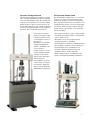
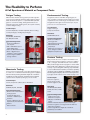
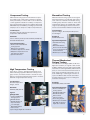
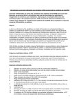
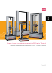
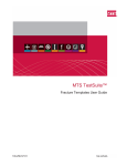
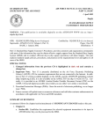
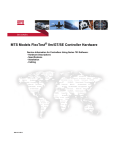
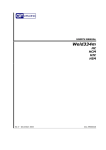
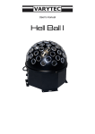
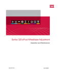
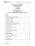
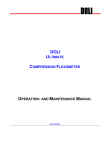
MTS 810 & 858 Material Testing Systems
Versatile, multipurpose
servohydraulic testing systems
for static and dynamic tests
l
MTS 810 & 858 Test Systems
Meeting the Full Spectrum of Testing Needs
Superior Testing and Global Support for all Environments
Test engineers worldwide rely on MTS Material Testing Systems and unrivaled global support to achieve
outstanding results for both static and dynamic material and component testing. Renowned for their
unmatched accuracy, flexibility, high performance, and innovative standard features, these systems provide for years of superior testing for all types of test and lab environments. With a large selection of fully
fatigue-rated MTS load units, control technology and accessories to choose from, tightly integrated systems
can be easily configured to meet an extremely wide array of test requirements.
Unmatched Accuracy
An integral actuator design, stiff,
low-mass crossheads, and special
force transducers deliver superior
axial and lateral stiffness.
Precision-machined columns and
actuator rods, and laser-guided
factory alignment ensure unprecedented alignment accuracy.
Highly accurate MTS load cells
exhibit low hysteresis and longterm stability.
Linear Variable Differential
Transducers mounted co-axially
with actuators deliver precise
actuator position measurement.
High Performance
Lightweight crossheads and stiff
components reduce load frame
deflections and increase performance envelopes.
Extremely low friction actuators
and high response servovalves
ensure superior test control.
Close-coupled accumulators
enable high frequency servovalve response, resulting in low
distortion and reduced line noise.
Hydraulic service manifolds provide smooth ramping of system
pressure to ensure precise control
during system start-up.
Flexibility
Innovative Features
Five-port servovalves ensure that
pressure changes – low-to-high,
high-to-low, and rapid shutoff are made under system control to
guarantee smooth transitions.
Local hydraulic station control
integral with actuator-mounted
manifold provides unmatched
convenience and First-on/Last-off
management of hydraulic power.
Off-Low-Slow-High pressure
control provides true bumpless
start and protects specimens.
Force-limited stroke control for
specimen insertion protects both
operators and specimens.
MTS load units perform both
highly accurate monotonic tests
and dynamic test applications.
Flexible test spaces, hydraulic
lifts and locks, and conveniently
placed controls facilitate easy
crosshead positioning.
MTS servovalves are available in
a wide variety of force and flow
capacities.
810 systems can accommodate up
to two servovalves - port shut-offs
allow operation of one or both
valves.
MTS load units require no special
mounting or foundation.
MTS Proven Control Solutions
FlexTest SE & GT Digital servocontrollers from MTS make up a
powerful array of reliable, flexible
and easy-to-use controllers designed
to address the full spectrum of
material and component testing
needs. These systems employ robust
VME-based MTS hardware and provide the pricing flexibility to accommodate a broad range of budgets.
An array of MTS material testing
software perform test definition,
test execution, and report generation for virtually all types of material
tests, including tension, bending, and
compression testing, fatigue life
studies, and fracture growth studies.
MTS software programs include:
MTS’s MultiPurpose TestWare®
for flexibility to meet the demands
of quickly changing test requirements in your standard and nonstandard testing applications.
MTS TestWorks® to perform all of
your tensile, flex, compression
and peel/tear tests, we well as
complicated non-standard tests.
MTS Fatigue and Fracture Testing
Software for general-purpose and
material-specific testing applications.
Material Testing Continuum
5 kN
(1 kip)
Force Range
Range of Available
Performance
Specimen Size
Test Type
2
100 kN
(22 kip)
858
Moderate
Plastics
250 kN
(55 kip)
High
Elastomers
Subsized
Tension • Bend
Compression
•
Aluminum
Standard
500 kN
(110 kip)
Very High
Composites
Steel
Medium
Super Alloys
Large
• Durability • High Cycle Fatigue • Low Cycle Fatigue
Creep • Fatigue Crack Growth
•
Fracture Toughness
810
Material Strength
25 kN
( 5.5 kip)
Versatile, Configurable 810
The 810 Material Testing System delivers a broad
array of testing capabilities for both low and high
force static and dynamic testing. By selecting from
a variety of force capacities, servovalve flow ratings,
pump capacities, software, and accessories, the
floor-standing 810 system can easily be configured
to meet your specific material or component testing needs. The versatile 810 system features:
Force ranges from 25 kN
(5.5 kip) to 500 kN (110 kip)
A wide performance range see Performance Curves on
pages 20–23
The ability to test materials
ranging in strength from
plastics to aluminum, composites and steel
A large test space to accommodate standard, medium
and large size specimens,
grips, fixtures and environmental subsystem
The capability to perform
a wide variety of test types
from tensile to high cycle
fatigue, fracture mechanics,
and durability of components
Full Featured, Compact 858
The 858 Material Testing System is a cost-effective
choice for low force static and dynamic testing
applications. Designed to preserve valuable floor
space, the 858 load unit can fit conveniently on an
existing laboratory bench, or sit on its own portable,
custom cart. While extremely compact, the 858
system provides a broad range of test enhancing
features, including:
Force ranges from 5 kN (1.1 kip) to 25 kN (5.5 kip)
A moderate performance range - see Performance
Curves on pages 24–27
The ability to test lower strength materials
ranging from plastics to aluminum
Accommodation of subsized to standard specimens
The capability to perform tension, compression,
bend and fatigue tests; specialized tests for
biomedical and biomechanical testing; and
durability testing on small components
Wide column spacing to accommodate larger
fixtures, environmental chambers and furnaces
3
The Flexibility to Perform
A Full Spectrum of Material or Component Tests
Fatigue Testing
Environmental Testing
MTS FlexTest material testing systems provide high stiffness, precision-aligned load frames with integral actuators.
When the FlexTest system is coupled with MTS patented
grips for consistent loading, and alignment fixtures for
minimizing specimen bending strain, the system is ideally
suited for fatigue testing.
Integrated solutions with MTS designed grips, fixtures, chambers and extensometers fulfill your testing
requirements over a wide range of temperatures. This
integrated solution gives assurance that you can put
your focus on successful results.
Test Examples
Constant Amplitude, Variable Amplitude, Block Loading,
Low Cycle Fatigue, and High Cycle Fatigue
Standards
ASTM E606, ASTM E466,
ISO 1099, ISO 12106
Typical Configuration
FlexTest 810 Material
Test System
646 or 647 Multi-Purpose
Axial Wedge Grips
634.11/31 Axial Extensometer
Basic or MultiPurpose
TestWare® testing software
Cyclic Fatigue TestWare®
testing software
Monotonic Testing
Your monotonic testing needs can be performed with precision and ease on a FlexTest material testing system equipped
with the industry leading TestWorks Application Software.
TestWorks provides powerful capabilities with simplified
operation and complete reporting of your test results.
Test Examples
Tensile, Compression, Bend, Stress Relaxation
Standards
ASTM E8, E9, E21, ISO 6892
Typical Configuration
FlexTest 810 or 858 Material
Testing System
TestWorks Application
Software or MultiPurpose
Testware
Variety of Mechanically and
Hydraulically Actuated Grips
Fixtures
Extensometers
4
Test Examples
Fatigue Testing of
Composite materials
Standards
ASTM D3479, D6115
Typical Configuration
FlexTest 810 Material
Testing System
MTS Model 651 Chamber
MTS Model 647 All
Temp Grips
MultiPurpose Testware or
Cyclic Fatigue TestWare
Adaptive Compensation
Fracture Testing
MTS provides the most complete Linear Elastic and
Elastic-Plastic Fracture Toughness solutions. In addition
to KIc , J-Integral, and CTOD fracture criteria software,
MTS provides Fatigue Crack Propagation solutions. MTS
Fracture Mechanics Application software improves the
accuracy of your testing while still being easy and flexible
to use. Predefined test templates provide the capability
of testing to various ASTM, ISO and British test standards.
Run-time graphical displays allow for monitoring the tests
in progress and in order to react to events as they occur.
Test Examples
Fracture Toughness,
Fatigue Crack Growth,
Crack Propagation, KIc, JIc
Standards
ASTM E399, E647, B645,
E1820, ISO 12737, 12108,
12135
Typical Configuration
FlexTest 810 or 858
Material Test System
640 grips or 642 Bend
Fixture
632.02 and 632.03 Clip-On Displacement Gages
Fracture Toughness or Fatigue Crack Growth Test
Application Software
Crack Length Monitor Application Software
MultiPurpose TestWare
Component Testing
Biomedical Testing
MTS material testing systems have flexible test space
and a wide range of performance packed in a durable
frame powered by a controller with a suite of advanced
control algorithms suitable for a variety of component
tests. FlexTest testing systems are software driven with
MTS MultiPurpose TestWare, providing a powerful and
simple process to easily run complex component tests.
MTS 858 material testing systems are designed
with many features to provide high performance
at the low forces needed for biomedical testing,
including very low friction actuators. These clean
and powerful systems are available with a wide
range of specialized grips, fixtures and environments to test biomedical materials and products.
Test Examples
Durability, Strength and Physical Properties of
Components and Assemblies
Test Examples
Hip Stem Fatigue, Dental Implant Wear, Bone
Screw Fatigue
Standards
Various Industry and Corporate Standards; ASTM, ISO,
FDA and DIN Standards
Typical Configuration
FlexTest 810 or 858 Material
Testing System
MultiPurpose TestWare
TestWorks Application Software
Adaptive Compensation and
Calculations Software
Specialized Fixtures
Standards
ASTM F1440, F2118
Typical Configuration
858 Material Testing
System
MTS Model 658 BioEnvironmental Chamber
Corrosion Resistant Pull
Rods and Fixtures
MultiPurpose TestWare
Thermal Mechanical
Fatigue Testing
High Temperature Testing
Super alloys, ceramics, and advanced materials need
advanced testing equipment. MTS has industry proven
grips, furnaces, and extensometers to elevate the capability of your FlexTest material testing system to meet the
demands of high temperature testing.
Test Examples
Elevated Temperature
Fatigue, Tensile
Standards
ASTM E8, E606, ISO 783
Typical
Configuration
FlexTest 810 Material
Testing System
MTS Model 653
MTS Model 647.10
Grips with watercooled wedges
MTS Model 632.53
Extensometer
Cyclic Fatigue Application Software
Thermal Mechanical Fatigue (TMF) Toolkit Test
Application Software, an original toolkit created
by MTS, simplifies the set up and running of TMF
tests without sacrificing flexibility. With real-time
plots you can monitor both thermal mechanical
wave shapes and advanced properties such as
strain hardening or softening as a function of
cycles. The MTS Toolkit includes automated
post-test analysis to assist you in creating test
summaries and reports.
Standards
ASTM E606, E2368, ISO T6164
Typical Configuration
FlexTest 810 Material
Testing System
MTS Model 646 Grips
MTS Model 632.53
Extensometer
Induction Heater
Air Cooling System
MultiPurpose TestWare
with TMF Toolkit Test
Application Software
5
Additional MTS Testing Capabilities
Axial Torsion Testing
MTS 809 Axial Torsion Materials Testing Systems provide
extremely stiff, high natural frequency load frames with integral
axial and torsional actuators. Axial Torsion loading of tubular
specimens has proven to be a valuable method for investigating
material response to both static and fatigue multi-axial stresses.
The MTS 858 A/T offers similar capabilities for lower force applications. These systems are ideally suited for small components,
Biomedical applications, and lower strength materials.
Typical Configuration
FlexTest 858 or 809 Axial-Torsional Material Test System
MTS Model 646 or 647 Axial-Torsional Wedge Grips
Two-Channel Controller
MTS Model 632.68 or 632.80 Extensometer
MultiPurpose TestWare
Planar Biaxial Testing
MTS capabilities include Planar Biaxial Testing
Systems. These systems are utilized when it is
desired to investigate true in-plane stress states
of materials, or biaxial loading of design elements.
System features include high load axis stiffness
for low stored energy and integral actuators
with high lateral stiffness to minimize buckling.
Powerful features in the FlexTest control software make centroid control easy to implement.
Typical Configuration
Bi-Axial Test Frame
MTS Model 647 Hydraulic
Wedge Grips
Four-Channel
Controller
Centroid Control
Algorithm
MultiPurpose
TestWare
High Force Testing
MTS high force testing systems are
rigid, 4-column testing units
designed especially for precise
application of high-force/high-displacement loads and fatigue
cycles. Load frames are available
to accommodate a wide variety of
specimens, components or full
scale test articles, and force capacities range from 100 to 3,000 tons or
higher. Grips, fixtures, and transducers are available for large size
specimens to complete the test
system.
Typical Configuration
MTS Model 311 High Force
Load Frame (up to 3000 tons)
MTS Model 647 Grips
(up to 1200 kN)
MultiPurpose TestWare or
TestWorks
6
High Frequency Testing
MTS 1000 Hz high-cycle fatigue test systems provide
accurate and reliable accelerated fatigue testing. The
systems maintain a high waveform fidelity while
running at high frequency, as well as highly accurate
control made possible with an MTS high response
voice coil servovalve and AdapTrac control software.
Typical Configuration
1000 Hz High-Cycle Fatigue Test System
MTS Model 318.50S Load Frame
High Performance Actuator with 25 kN,
+/- 25.4 mm
Low-mass grips and fixtures
High-flow voice coil servovalve
MultiPurpose TestWare with
AdapTrac Software
Elastomer Testing
Elastomer test systems meet the high frequency,
high precision testing requirements of automotive
and material industries. The standard configuration
features a frequency range of 0.01 to 1000 Hz, with
+/-10 kN force and displacements of +/-20 mm.
Designed for measuring dynamic properties such
as K*, phase, E*, tan delta, energy, and damping
coefficients over its wide frequency range.
Typical Configuration
1000 Hz High Frequency Elastomer Test System
Specially designed Model 831.50 Load Frame
(up to 10 kN)
FlexTest GT Controller (48 kHz acquisition rate)
MTS Model 505.07 SilentFlo Hydraulic Power
Unit
MTS Model 793.3x Elastomer Application
Software
High Rate Testing
High rate systems provide robust load frames
with high performance servohydraulic controls;
high-speed data acquisition; and TestWorks® software to provide operator interface, test analysis
and reporting. These systems provide reliable
results for automotive crash worthiness testing,
forging simulation and other high strain rate,
or high penetration rate testing needs.
Typical Configuration
MTS Model 819.1x Load
Frame (up to 100 kN)
High-flow
voice coil
servovalve
Low Mass
Grips
7
Components of the 810 System
D
Load Unit Assembly
A complete load frame assembly requires the
selection of the frame, actuator size, actuator
rod/load cell thread, and hydraulic service manifold. The servovalve(s) and other options are
selected separately.
The 810 system employs MTS Model 318 load
unit assemblies that are force rated up to 500 kN.
This floor mounted frame has high axial and lateral
stiffness that improves test accuracy and system
performance. This load frame is available in a variety of sizes and can be easily configured for many
different applications. Please see Performance
Curves on page 20 for more details.
Crosshead mounted load cell provides an accurate force reading for measurement and control.
The displacement transducer is integral to the
actuator for position measurement and control.
Other options such as crosshead mounted actuators, actuator antirotate, hydrostatic bearing actuators, and air isolator pads are available with the
318. Integral actuator design shortens the force
train providing higher lateral stiffness. Low friction actuator ensures the best possible test control
and resolution.
There are two hydraulic service manifold options
for the 318 Load Units. The 298.11 provides
OFF/ON pressure control while the 298.12 has
OFF/LOW/HIGH pressure control with a controlled
pressure transition to and from high pressure.
A
G
C
H
B
E
F
Specifications by Frame Configuration
Load unit specifications
Model
Force capacity (maximum)
Available actuator ratings
Vertical test space* (A)
Working height (B)
Column spacing (C)
Column diameter (D)
Base width (E)
Base depth (F)
Diagonal Clearance (G)
Overall Height (H)
Stiffness†
Weight
318.10
318.25
318.50
100 kN (22 kip)
15, 25, 50, 100 kN
(3.3, 5.5, 11, 22 kip)
1308 mm (51.5 in)
889 mm (35 in)
250 kN (55 kip)
100, 250 kN
(22, 55 kip)
1625 mm (64 in)
889 mm (35 in)
500 kN (110 kip)
250, 500 kN
(55, 100 kip)
2108 mm (83 in)
889 mm (35 in)
533 mm
64 mm
864 mm
610 mm
2718 mm
2540 mm
2.6 x 10 8 N/m
500 kg
(21 in)
635 mm
(2.5 in)
76 mm
(34 in)
1003 mm
(24 in)
762 mm
(107 in)
3251 mm
(100 in)
3023 mm
6
(1.5 x 10 lb/in) 4.3 x 10 8 N/m
(1100 lb)
910 kg
(25 in)
762 mm
(3 in)
102 mm
(39.5 in)
1245 mm
(30 in)
914 mm
(128 in)
3835 mm
(119 in)
3581 mm
6
(2.4 x 10 lb/in) 7.5 x 10 8 N/m
(2000 lb)
1770 kg
*Test space is the maximum distance between the load cell and the actuator with the actuator fully retracted.
Optional extended height versions available, add 300 mm (12 inches) to pertinent dimensions.
at each load unit’s full fatigue rating with its crosshead raised 1270 mm (50 in.) above the base plate.
†Determined
8
(30 in)
(4 in)
(49 in)
(36 in)
(151 in)
(141 in)
(4.3 x 1 106 lb/in)
(3900 lb)
Columns
Crosshead
Designed for a high natural
frequency.
High stiffness for precise displacement measurement and
increased dynamic performance.
Alignment fixture
(optional)
Grips and fixtures
(optional)
The largest variety of hydraulic
and mechanical grips and
loading fixtures are available
from MTS.
Precise load train alignment in minutes.
Force transducers
Grip controls
(optional)
Solid steel for high stiffness and chrome plated for
long life and easy cleaning.
Precision machining maintains load unit alignment
over their entire length.
Strain gage design is accurate for both static and
dynamic testing.
Many force ratings are available to meet your
specific needs.
Load unit control module
Provide fingertip control of
hydraulic grips and clamping
pressure.
Puts control of the hydraulic lifts and locks for repositioning the crosshead at a convenient location.
Emergency stop shuts off hydraulics.
Isolator pads
Dampen external vibrations.
Hydraulic lifts and locks
Allow easy repositioning of the crosshead and fast
crosshead locking/unlocking.
Options for MTS 318
Load Unit Assemblies
Hydraulic actuator
Integrally mounted in the base plate to shorten
the force train for increased stiffness, better side
load capability, and more accurate test results.
Available in a variety of force ratings and stroke
lengths.
Includes a co-axially mounted displacement
transducer for precision displacement control and
measurement.
Actuator manifold
Air bag vibration isolators
Alignment adjustment fixtures
Extended length columns
Actuator stroke lengths
Test area guard
Crosshead actuator mounting
Hydrostatic actuator bearings
Actuator anti-rotate
Low force load transducers
Low force actuator/high stiffness load unit combinations
Actuator rod bellows
Provides mounting for up to two servovalves of
equal or different sizes.
Mounted on the actuator for the highest possible
response and most accurate test control.
Available with close coupled accumulators that
help minimize hydraulic pressure fluctuations for
improved test control and data accuracy.
9
Components of the 858 System
D
The 858 employs a MTS Model 359 load unit that is
fatigue-rated at 25 kN (5.5 kip). This freestanding load
unit can be operated at frequencies up to 30 Hz without
having to secure it to the lab bench or the optional cart
that is available from MTS.
The 359 load unit features a generous horizontal test
space between the columns, which enables easy specimen mounting. Load units with extended columns can
be ordered to gain additional vertical free space.
The basic load unit configurations each use an integral
crosshead-mounted linear actuator with an attached manifold. This provides close-coupled servovalves and accumulators for improved performance and reduced pressure
fluctuations.
A selection of linear actuators are available to achieve a
wide range of scale force data from 5 kN to 25 kN. The
full-scale force is dependent on the output pressure of the
particular MTS hydraulic power unit selected. Optional
hydraulic lifts can be provided to facilitate repositioning
of the crosshead. See Performance Curves on page 24.
G
H
A
C
E
B
F
Specifications By Frame Configuration
Load unit specifications
Model
Force capacity §
359.15
Standard
359.15
Extended
359.25
Standard
359.25
Extended
15 kN (3.3 kip)
15 kN (3.3 kip)
25 kN (5.5 kip)
25 kN (5.5 kip)
Vertical test space* (A)
789 mm (31.0 in)
1289 mm (50.7 in)
789 mm (31.0 in)
1289 mm (50.7 in)
Working height (B)
278 mm (10.9 in)
278 mm (10.9 in)
278 mm (10.9 in)
278 mm (10.9 in)
Column spacing (C)
460 mm (18.1 in)
460 mm (18.1 in)
460 mm (18.1 in)
460 mm (18.1 in)
Column diameter (D)
76 mm (3.0 in)
76 mm (3.0 in)
76 mm (3.0 in)
76 mm (3.0 in)
Base width (E)
625 mm (24.6 in)
625 mm (24.6 in)
625 mm (24.6 in)
625 mm (24.6 in)
Base depth (F)
527 mm (20.8 in)
527 mm (20.8 in)
527 mm (20.8 in)
527 mm (20.8 in)
1378 mm (54.25 in)
1879 mm (74.0 in)
1378 mm (54.25 in)
1879 mm (74.0 in)
1687 mm (66.4 in)
2187 kN (86.1 in)
1687 mm (66.4 in)
2187 kN (86.1 in)
Diagonal Clearance (G)
Overall Height (H)
Stiffness†
Weight
275x106 N/m (1.57x10⁶ lb/in) 275x106 N/m (1.57x10⁶ lb/in) 275x106 N/m (1.57x10⁶ lb/in) 275x106 N/m (1.57x10⁶ lb/in)
(measured)
(measured)
(measured)
(measured)
192 kg (425 lb)
231 kg (508 lb)
192 kg (425 lb)
231 kg (508 lb)
* Test space is the maximum distance between the load cell and the actuator with the actuator fully retracted.
† Determined at each load unit’s full fatigue rating with its crosshead raised 800 mm (31.5 in.) above the base plate.
§ Rated actuator force at 21 MPa (3000 psi).
Specifications are subject to change without notice. Contact MTS to verify critical specifications.
10
Columns
Crosshead
Designed for a high natural
frequency.
High stiffness for precise displacement measurement and
increased dynamic performance.
Adjustable position to provide
test space flexibility.
Solid steel for high stiffness and chrome
plated for long life and easy cleaning.
Precision machining maintains load unit
alignment over their entire length.
Force transducers
Strain gage design is accurate for both
static and dynamic testing.
Many force ratings are available to meet
your specific needs.
Alignment fixture (optional)
Precise load train alignment
in minutes.
Load unit control module
Grip controls
(optional)
Provide fingertip control of
hydraulic grips and clamping
pressure.
Puts control of the hydraulic lifts for
repositioning the crosshead at a
convenient location (optional).
Emergency stop shuts off hydraulics.
Isolator pads
Dampen external vibrations.
Actuator manifold
Provides mounting for servovalve.
Mounted on the actuator for the highest
possible response and most accurate test
control.
Close coupled accumulators that help
minimize hydraulic pressure fluctuations
for improved test control and data accuracy.
Local control of hydraulic pressure with
proportional valve for bumpless start.
Options for MTS 359
Load Unit Assemblies
Hydraulic lifts (optional)
Allow easy repositioning of the crosshead.
Hydraulic actuator
Integrally mounted in the crosshead to
shorten the force train for increased
stiffness, better side load capability, and
more accurate test results.
Available in two force ratings.
Includes a co-axially mounted
displacement transducer for precision
displacement control and measurement.
Air bag vibration isolators (G)
Alignment adjustment fixtures
Extended length columns (B)
Actuator stroke lengths (F)
Test area guard (F)
Crosshead actuator mounting
Hydrostatic actuator bearings
Actuator antirotate (C)
Low force load transducers (D)
Hydraulic lifts (A)
Specially designed cart (E)
11
FlexTest SE & GT Control Options
MTS 810 systems include your choice of FlexTest
SE or GT digital servocontrollers. FlexTest controllers are reliable, and easy-to-use, and are designed
to address the full spectrum of material and component testing needs. With a common set of proven
and reliable hardware and software, and capabilities ranging from one to eight channels and one to
four stations, this family of digital controllers provides the pricing flexibility to accommodate a
broad range of budgets, as well as a comprehensive set of features for performing the material
testing application specific to your particular testing needs.
Both FlexTest GT and PC driven FlexTest SE controllers employ proven MTS Model 793 Software used daily on thousands of MTS controllers worldwide. This powerful control package features a
Windows multi-tasking operating system that allows
you to define new tests, acquire data, and analyze
results of prior and current tests while other tests
are still in progress. Model 793 Software makes it
easy to integrate your FlexTest control system into
your organization’s computer networks and to
share data with other networked equipment. It
also allows you to take advantage of the full array
of proven MTS test application software.
FlexTest SE Plus
A high capacity control solution for more demanding single-channel,
single-station material and component testing
The PC driven FlexTest SE Plus digital controller
delivers real-time closed-loop control of demanding single-channel, single-station tests. FlexTest SE
Plus hardware includes a high-power VME processor capable of yielding a 6kHz update rate, a single
2- or 3-stage valve driver, up to 5 digital universal
conditioners (DUCs), an encoder interface board,
and a set of 6 auxiliary input channels. The Plus
model is also capable of supporting a temperature
control system via serial communications.
Additional capabilities include:
Bumpless start
Hydraulics-on mode-switching
Auto-zeroing
Auto-tuning
Typical FlexTest SE Plus Configuration
One valve driver (2-stage or 3-stage)
Two digital universal conditioners (DUCs)
One analog input – for data signal or external
program
Three analog outputs
Digital inputs and outputs for interlock and
user-defined use
Popular Options
12
Basic TestWare, MultiPurpose TestWare,
TestWorks, and Fatigue and Fracture Software
Up to three additional DUCs
Set of six additional A/D inputs
On-line scope
Adjustable arm or stand
Saving and restoring PID settings
On-line scope to observe signals
Digital display of measurements
Full-range calibrations
Integrates with third party data acquisition
and program generation
Integral Front Panel Controls
The FlexTest SE model features front panel system controls that supplement the PC interface to
facilitate convenient test monitoring and specimen handling, eliminating the need
for an additional
Remote Station
Control pendant.
This intuitive
front panel combines
a sharp, multi-color display with easy-to-read
graphics and an array of
controls including dedicated menu keys, a keypad,
HPS, HSM, program run-stop-hold, E-stop, and a
rotary adjustment knob.
Portability and Convenience
Lightweight FlexTest SE controllers are designed for
portability, featuring a multiposition handle to facilitate easy transport to other test locations. Additionally, there are a variety of ways to position a
FlexTest SE controller either on or near a load frame:
it can be secured to an adjustable arm attached
to the load frame itself; mounted on a portable,
adjustable stand near the load frame; or it can simply be placed on a table or cart.
FlexTest GT
A proven control solution for complex multichannel,
multistation material and component testing
The FlexTest GT digital controller features the
power and flexibility to deliver high speed, realtime closed-loop control, data acquisition, function generation, and transducer conditioning for
multichannel, multistation applications, allowing
several test systems to be driven from one controller. It accommodates up to 32 modules that
can be distributed among 8 channels and 4 stations as required, with the option to add 16 user
programmable digital inputs and digital outputs.
Hardware Driven Flexibility
The flexible design of the FlexTest GT lets you
reconfigure the system easily as your needs
change. By adding hardware modules you can
expand your system’s capabilities and customize
it for a wide range of tests. This includes the ability to use externally conditioned signals as control
modes. In addition, you can use D/A signals as
low-rate control channels for signals like pressure
or temperature.
Portable Remote Station Control
The optional Remote Station Control (RSC) provides a convenient, portable control interface for
carrying out simple operations, such as specimen
handling and test setup. The FlexTest GT requires
an RSC to comply with CE safety standards for
material testing applications. The RSC simplifies
many operations, including operating the hydraulic
controls, moving the actuator to mount specimens, and starting and stopping tests. In addition
Remote Station
Control Option
Programmable display shows
sensor outputs and the current
control mode. The display can
be used to change control
modes and zero sensors.
Actuator position
control lets you engage
the actuator manually.
to hydraulic controls and an interlock indicator,
it provides run, stop, and hold controls; a display
screen and function keys; and an actuator positioning control for specimen loading. Once a specimen
is loaded, transducers can be auto-zeroed from the
computer, or from the RSC. For multichannel systems the actuator command toggles between axes.
Multistation configurations require a dedicated RSC
per station. The lightweight RSC can be located on
the PC table or cart if this is near the load frame,
or it can be mounted on a stand by the load frame
if the PC is not located nearby.
Typical FlexTest GT Configurations
One valve driver (2-stage or 3-stage) per
control channel
Two digital universal conditioners (DUCs) per
control channel
Digital inputs and outputs for HSM and HPU
interlock
Popular Options
Start, stop, or hold
your test program.
Command the hydraulic
pressure of the hydraulic
service manifold.
Indicator signals
that an interlock
has been tripped.
Basic TestWare, MultiPurpose TestWare,
TestWorks , and Fatigue and Fracture Software
Additional DUCs
Auxiliary A/D inputs
Set of 16 digital inputs and 16 digital outputs for
user-defined operation
Station stop
13
FlexTest Digital Servocontrollers
Addressing the full spectrum of material and component testing needs
FlexTest SE Basic
The FlexTest SE Basic is a cost-effective control
solution for simple single-channel, single-station
strength or fatigue tests on materials or components for which a simple command and a single
result are all that is required. Examples include:
Tensile test, reporting peak load and maximum
elongation
High Cycle Fatigue test, reporting number of
cycles to failure
Durability, reporting material degradation after
block-cyclic loading
Integrates with third party data acquisition and
program generation
FlexTest SE Plus
Coupled with a PC running MTS 793 software,
the FlexTest SE Plus is a higher capacity control
solution for more demanding single-channel, single-station materials tests. It supports more hardware and software options than the Basic model.
The FlexTest SE Plus allows you to:
14
Take advantage of a wide array of proven MTS
test application software to run a wide variety
of tests
Customize and automate test procedures
Acquire and store test data
Generate test reports
Network to other PCs
Monitor test status from remote PCs
FlexTest GT
The FlexTest GT is a proven control solution for performing complex materials and
component testing. Capable of supporting
up to 8 channels and multiple stations, the
FlexTest GT enhances productivity by
allowing you to manage several stations
from one PC screen. Or, if you prefer, the
PC-per-Station option enables you to
employ additional PCs so different opera-
tors can run their respective test stations without having to share a PC. This
option also makes it possible to support
test stations in different locations. The
FlexTest GT runs with MTS 793 software
and a multitasking Windows™ operating
system, allowing you to take advantage
of the full array of proven MTS test
application software.
Ethernet
Hub
OFFIC
CONNE
ECT
MAIN
OFFIC RPC
ES
3 Com
LAN
OFFIC
CONNE
ECT
MAIN
OFFIC RPC
ES
3 Com
15
Comparison of FlexTest SE and
FlexTest GT Controllers
FlexTest SE
PC Automation
Max update rate
Built-in A/D inputs
Built-in D/A outputs
Valve Drivers
Conditioners
DIO
Basic TestWare
MultiPurpose TestWare
Testworks 4
Fatigue & Fracture
Remote Station Control
Remote Setpoint Adjust
Temp Control H
A
B
C
D
E
F
G
H
FlexTest GT
BASIC with
2kHz
processor
BASIC with
6kHz
processor
PLUS
2-Channel
Opt
2kHz
1
3
1
up to 3 C
4 pair D
Opt F
Opt F
No
No
No
Opt F,G
No
Opt
6kHz
1
3
1
up to 3 C
4 pair D
Opt F
Opt F
Opt F
Opt F
No
Opt F,G
Opt F
Yes
6kHz
1
3
1
up to 5
4 pair D
Yes
Opt
Opt
Opt
No
Opt G
Yes
Yes
6kHz
1
3
2
up to 6 C
4 pair D
Yes
Opt
Opt
Opt
No
Opt G
Yes
A
A,B
Yes
6kHz
0
0
up to 8
up to 24 C
Opt E
Yes
Opt
Opt
Opt
Opt
Opt G
Yes
Can upgrade with PC Automation in the field.
If PC automation is included use PLUS or 2-Channel model column information.
Pending other hardware options selected.
One pair dedicated to hydraulic interlock, three pair definable by user.
Set of 16/16 Digital Inputs/Outputs are available as an option.
Requires PC automation.
Requires available IO Carrier slot and encoder interface board.
Via serial communications to appropriate temperature control system, for non-TMF applications.
If a customer wants a stand-alone controller to run tests without requiring a PC and expects to need FlexTest SE Plus model capabilities in
the future then the 6kHz processor upgrade should be ordered with the FlexTest SE Basic model controller.
Specifications (descriptions in gray shading apply to both FlexTest SE and FlexTest GT models)
Parameter
FlexTest SE
FlexTest GT
Station configurations
Number of station
1 station
up to 4 stations
Servo Control
Control channels
Control modes
DDC loop update rate
1 (FlexTest SE Basic and Plus models)
up to 8 channels
2 (FlexTest SE 2-Channel model)
Any connected transducer (typically load, strain or displacement), calculation (option
for automated applications), and load-limited displacement for specimen loading.
6kHz (2kHz for Basic model unless optional
6kHz
upgrade processor provided)
Data Acquisition
Resolution
Sample rate
Number of channels
16 bit
Up to 6kHz sampling rate
1 per internal conditioner, 6 per Analog input board.
All channels simultaneous sample and hold.
Signal Conditioners
Resolution
Data sample rate
Signal Processing
Program Generation
Frequency range
Waveforms
Maximum ramp time
16
19 bit
100kHz
32 bit, double precision computation
32 bit
0.001 Hz to 600 Hz
Sine, square, triangle, ramp, and any user-defined waveform
>1000 years
(Specifications continued)
Parameter
Valve Drive - 2 Stage (493.14)
Maximum output
Dither
FlexTest SE
FlexTest GT
Dual balance differential current source
25 or 50 mA (selectable), +/- 20V across 1Kohm load
Adjustable, 0 to 5 V p-p, frequency adjustable 1 to 4915 Hz
Valve Drive - 3 Stage (493.15)
Maximum drive current
Dither
Excitation
Input
Feedback
Digital Universal Conditioner
Excitation
Transducer ID cable
Interlocks
Analog Inputs
Input channels
Input voltage
50mA at +/- 20V
Adjustable, 0 to 5 V p-p, frequency adjustable 1 to 4915 Hz
Balanced AC-coupled output 100mA max +/-20V frequency set to 9.8kHz
Differential AC-coupled with adjustable gain and zero
Proportional and differential
For resistive or reactive type transducers
Balanced constant voltage or constant current 0-20 VDC, supports
4- or 8-wire connections
Supports shunt calibration value. Bridge-balancing and completion for
quarter- and half-arm bridges.
Excitation failure in hardware, conditioner saturation in software
16-bit resolution
1 built-in, plus 6 per optional 493.45 board
22 V p-p maximum
6 per each optional 493.45 board
Analog Outputs
Output channels
Output voltage
Max load
Digital I/O
Input
Output
3 built-in, plus 6 per optional 493.46 board
+/-10V
2000 ohm, 1000 pf
6 per each optional 493.46 board
4 in/4 out (1 pair dedicated to hydraulic interlock)
16 in / 16 out (493.72 option)
ON voltage = 2.7-26VDC @ 0.5mA min. Input Resistance = 2K ohm
Open Collector Open Emitter; 30VDC max; VCE max = 1V @ 6mA; IC max = 20mA
Hydraulics
Hydraulic service manifold
contact outputs
HSM proportional output
Run/stop contact outputs
1 A @ 24 V
20 to 800mA; 2 or 4 sec ramp on; 0, 2, or 4 sec ramp off (selectable)
1A @ 30 VDC (must use one of above Digital I/O)
2A @ 30 VDC
Digital Controller Dimensions
Height
Width
Depth
Weight
13 cm (5.2 in)
43 cm (17 in)
43 cm (17 in)
8.6 kg (19 lb)
61 cm (24 in)
37 cm (14.5 in)
66 cm (26 in)
45.4 kg (100 lb)
Environmental
Temperature
Relative humidity
5°C to 40°C
10% to 85% non-condensing
Power Input
Input voltage *
Input surge
Static current
Circuit protection
100-240 VAC, 47-63 Hz
<50A max for 1/2 cycle
<100A max for 1/2 cycle
~4A @ 115VAC, ~2A @ 230VAC
~12A @ 115VAC, ~6A @ 230VAC
Short circuit protection by duty cycle current foldback with automatic recovery
Standards
EMC
Safety
Communication to PC
Online Documentation
EN 5008-2 (1995) Electromagnetic compatibility, Generic immunity standard,
Part 2: Industrial environment
EN 55011 (1991) Limits and Methods of Measurement of Radio Interference
Characteristics of Industrial,
Scientific and Medical (ISM) Equipment
EN 61010-1 (1993) Safety requirements for electrical equipment
for measurement, control, and laboratory use
Dedicated 100 Mbit Ethernet connection with 10 Mbyte/sec data transfer rate
FlexTest SE User manual
System Software manual
MultiPurpose Testware manual
System Software manual
MultiPurpose Testware manual
* The specifications shown conform to CE compliance. The specification allows for +/-10% of the values stated. The actual voltage
that the FlexTest controllers can operate within is 90-264 VAC.
17
HPU Solutions
Hydraulic Power Unit
MTS has a hydraulic power unit (HPU) that fits
your needs. We offer units with flow ratings from
3.8 to 114 Lpm (1.5 to 30 gpm) or even higher if
you need it.
The HPU most commonly used with the 810
test system is the SilentFlo™ model 505.07. This
super-quiet pump operates at an amazingly low 58
dB(A). That’s as quiet as your typical office photocopier—no pump room required!
The SilentFlo 505.07 HPU provides continuous
pressure of 21 MPa (3000 psi) and a flow rating of
26.5 Lpm (7 gpm) when operating @ 60 Hz. The
SilentFlo HPU is a fully integrated machine including both the hydraulic system components and the
fuses, electrical disconnect, motor starters, and
control logic. Simply connect electric power and
water to the unit and it’s ready to run.
SilentFlow HPUs feature advanced technology
and integrated controls that make them easy to use.
They utilize variable displacement pump units for
maximum electrical efficiency, automatic interlocks
that protect against low oil level and high temperature conditions, and 3-micron return line filtration designed specifically for servohydraulic
testing system use.
The SilentFlo 505.07 hydraulic power unit
Hydraulic power supply specifications
Model
Flow rate
At 50 Hz
At 60 Hz
505.07
505.11
lpm
gpm
22.7
26.5
6
7
lpm
41.6
41.6
505.20
gpm
11
11
lpm
62.5
75
505.30
gpm
16.5
20
An additional economical MTS Hydraulic Power
Units is available for testing with lower flow
requirements. These high-efficient, low-noise
pumps are used to produce smooth hydraulic
fluid output, low in entrained air and free of pressure spikes that can produce erratic test results.
Highly effective filtration systems protect against
silting that degrades system performance, distorts
data, and damages machinery.
Specifications
Model
Flow rate
At 50 Hz
At 60 Hz
512.14
lpm
gpm
12.5
15.1
3.3
4.0
Water Cooled
18
Air Cooled
lpm
100.7
113
gpm
26.6
30
System Lifecycle Management
Extend Your System Life – Improve Your ROI
Let MTS help you efficiently and cost-effectively
maintain and enhance your lab resources with our
Lifecycle Management approach. As a result you
will improve the return on your investment by:
Extending your systems useful life
Expanding your systems testing capabilities
Enhancing your systems testing throughput
World Class Field Service
One of the keystones of our
Lifecycle Management program
is the 250+ highly trained and
skilled professional Field Service
Engineers stationed in more
than 60 cities around the world.
A wide variety of Support
Service offerings are available to
maintain peak effectiveness.
Contact your MTS FSE at:
http://www.mts.com/worldwide/continents.asp
Trusted and Experienced
Testing Partners
MTS is more than a leading
physical test equipment supplier. The MTS staff of materials
scientists, engineers and technicians are known around the world for
their expertise, experience and insight into virtually
all types of material and finished product testing.
Ongoing Software Assurance
The most economic and automatic way to make
way to make sure you are always running the latest
and greatest software on your MTS controllers is to
enroll in the MTS Software Assurance Program and
guarantee the maintenance, enhancement and support of your system’s performance.
Productivity-Enhancing Training
Maximize the productivity and lifetime of your test
system investment with our hands-on learning
courses. Our courses cover systems and software
operation and maintenance, testing principles,
methodologies, and applications. Learn more at:
http://www.mts.com/training/training.asp?Market=All
Proven MTS Software
Both FlexTest GT and PC-driven FlexTest SE controllers employ proven MTS Model 793 Software used daily on thousands of MTS controllers worldwide. This powerful control package features a
Windows multi-tasking operating system that allows
you to define new tests, acquire and share data, and
analyze results of prior and current tests while other
tests are still in progress. Take advantage of the full
array of proven MTS test application software:
Basic TestWare
Software
enables you set
up and run simple monotonic
and cyclic tests
by defining the
rate, frequency,
amplitude, and
mean for sine,
triangle, square,
and ramp command signals.
Capture data
while a test is
running and store it in standard formats for easy
importation into your favorite analysis, plotting,
and word processing programs.
MultiPurpose TestWare (MPT) – easy-to-use “drag
and drop” environment for building standard and
nonstandard tests. Link basic processes, including function generation, data acquisition, events,
and triggers, to quickly and easily build complex
tests. Use your favorite spreadsheet program or
analysis package to analyze, plot, and report data.
TestWorks Software enables you to easily define
and run test methods for tensile, compression,
flexure, and other simple monotonic tests. Acquire
and manipulate data from displacement, time, load,
and up to six strain channels, as well as store test
setup data along with test results, so you can easily
determine how a test was run and repeat it as
desired.
High-Cycle, Low-Cycle, and Advanced Low-Cycle
Fatigue Testing Software is designed for the definition, execution, and analysis of constant amplitude, high-cycle and low-cycle fatigue tests.
KIC and JIC Fracture Toughness Testing Software
performs plane-strain and plane-stress fracture
toughness tests on compact tension, C(T), and
bend, SE(B), test specimens.
Programming Libraries include drivers for
LabVIEW, Visual Basic, and C++ programming
environments to assist you in developing customized test applications
19
810 Performance Curves
The graphs on the following pages illustrate the
dynamic performance characteristics of a sampling
of configurations available for the 810 and 858
systems. Actual performance will depend upon the
Load Frame Model: 318.10
Actuator Static Force:
Actuator Nominal Stroke:
System Oil Pressure:
Load Frame Model: 318.10
Actuator Static Force:
Actuator Nominal Stroke:
System Oil Pressure:
20
100 kN
25 kN
150 mm
210 bar
100 kN
50 kN
150 mm
210 bar
(22 kip)
(5.5 kip)
(6 inches)
(3000 psi)
(22 kip)
(11 kip)
(6 inches)
(3000 psi)
specimen under test, grips and fixtures employed,
and the components selected in your system. MTS
can assist you in configuring a system to meet your
test requirements.
ServoValve(s): 252.25G x (1)
Grip: 647.02
HPU: 505.20 60 Hz
57 lpm
6.8 kg
76 lpm
(15 gpm)
(15.0 lbs.)
(20 gpm)
ServoValve(s): 252.25G x (1)
Grip: 647.10
HPU: 505.20 60 Hz
57 lpm
30.4 kg
76 lpm
(15 gpm)
(66.9 lbs.)
(20 gpm)
Load Frame Model: 318.10
Actuator Static Force:
Actuator Nominal Stroke:
System Oil Pressure:
100 kN
100 kN
150 mm
210 bar
(22 kip)
(22 kip)
(6 inches)
(3000 psi)
ServoValve(s): 252.23G x (1)
Grip: 647.10
HPU: 505.20 60 Hz
19 lpm
30.4 kg
76 lpm
Load Frame Model: 318.10
Actuator Static Force:
Actuator Nominal Stroke:
System Oil Pressure:
100 kN
100 kN
150 mm
210 bar
(22 kip)
(22 kip)
(6 inches)
(3000 psi)
ServoValve(s): 252.24G x (2)
Grip: 647.10
HPU: 505.07 60 Hz
76 lpm (20 gpm)
30.4 kg (66.9 lbs.)
26.5 lpm (7 gpm)
(5 gpm)
(66.9 lbs.)
(20 gpm)
21
810 Performance Curves (continued)
22
Load Frame Model: 318.25
Actuator Static Force:
Actuator Nominal Stroke:
System Oil Pressure:
250 kN
250 kN
150 mm
210 bar
(55 kip)
(55 kip)
(6 inches)
(3000 psi)
ServoValve(s): 252.24G x (1)
Grip: 647.25
HPU: 505.11 60 Hz
38 lpm
(10 gpm)
77 kg
(169 lbs.)
41.6 lpm (11 gpm)
Load Frame Model: 318.25
Actuator Static Force:
Actuator Nominal Stroke:
System Oil Pressure:
250 kN
250 kN
150 mm
210 bar
(55 kip)
(55 kip)
(6 inches)
(3000 psi)
ServoValve(s): 252.25G x (2)
Grip: 647.25
HPU: 505.30 60 Hz
114 lpm (30 gpm)
77 kg
(169 lbs.)
113.5 lpm (30 gpm)
Load Frame Model: 318.50
Actuator Static Force:
Actuator Nominal Stroke:
System Oil Pressure:
500 kN
500 kN
150 mm
210 bar
(110 kip)
(110 kip)
(6 inches)
(3000 psi)
ServoValve(s): 252.24G x (1)
Grip: 647.50
HPU: 505.11 60 Hz
38 lpm (10 gpm)
148 kg
(326 lbs.)
41.6 lpm (11 gpm)
Load Frame Model: 318.50
Actuator Static Force:
Actuator Nominal Stroke:
System Oil Pressure:
500 kN
500 kN
150 mm
210 bar
(110 kip)
(110 kip)
(6 inches)
(3000 psi)
ServoValve(s): 252.25G x (2)
Grip: 647.50
HPU: 505.30 60 Hz
114 lpm (30 gpm)
148 kg
(326 lbs.)
113.5 lpm (30 gpm)
* Systems illustrated include accumulation, pressure and return hoses selected to match the other component
ratings listed. Hydraulic power supplies have been selected to not limit performance provided by other components. Performances illustrated represent a mathematical prediction of system performance acting against a
spring specimen. Your MTS Sales representative can discuss these and other performance options available.
23
858 Performance Curves
The graphs on the following pages illustrate the
dynamic performance characteristics of a sampling
of configurations available for the 810 and 858
systems. Actual performance will depend upon the
24
specimen under test, grips and fixtures employed,
and the components selected in your system. MTS
can assist you in configuring a system to meet your
test requirements.
Load Frame Model: 359
Actuator Static Force:
Actuator Nominal Stroke:
System Oil Pressure:
25 kN
15 kN
100 mm
70 bar
(5.5 kip)
(3.3 kip)
(4 inches)
(1000 psi)
ServoValve(s): 252.22G x (1)
Grip: 647.01
HPU: 512.14 60 Hz
9.5 lpm (2.5 gpm)
4.1 kg
(9.0 lbs.)
15.1 lpm (4 gpm)
Load Frame Model: 359
Actuator Static Force:
Actuator Nominal Stroke:
System Oil Pressure:
25 kN
15 kN
100 mm
140 bar
(5.5 kip)
(3.3 kip)
(4 inches)
(2000 psi)
ServoValve(s): 252.23G x (1)
Grip: 647.01
HPU: 512.14 60 Hz
19 lpm (5 gpm)
4.1 kg
(9.0 lbs.)
15.1 lpm (4 gpm)
Load Frame Model: 359
Actuator Static Force:
Actuator Nominal Stroke:
System Oil Pressure:
Load Frame Model: 359
Actuator Static Force:
Actuator Nominal Stroke:
System Oil Pressure:
25 kN
15 kN
100 mm
210 bar
(5.5 kip)
(3.3 kip)
(4 inches)
(3000 psi)
ServoValve(s): 252.23G x (1)
Grip: 647.01
HPU: 505.07 60 Hz
25 kN
15 kN
100 mm
210 bar
(5.5 kip)
(3.3 kip)
(4 inches)
(3000 psi)
ServoValve(s): 252.24G x (1) 38 lpm (10 gpm)
Grip: 647.01
4.1 kg
(9.0 lbs.)
HPU: 505.07 60 Hz
26.5 lpm (7 gpm)
19 lpm (5 gpm)
4.1 kg
(9.0 lbs.)
26.5 lpm (7 gpm)
25
858 Performance Curves (continued)
26
Load Frame Model: 359
Actuator Static Force:
Actuator Nominal Stroke:
System Oil Pressure:
25 kN
15 kN
100 mm
210 bar
(5.5 kip)
(3.3 kip)
(4 inches)
(3000 psi)
ServoValve(s): 252.25G x (1)
Grip: 647.01
HPU: 505.11 60 Hz
57 lpm (15 gpm)
4.1 kg
(9.0 lbs.)
41.6 lpm (11 gpm)
Load Frame Model: 359
Actuator Static Force:
Actuator Nominal Stroke:
System Oil Pressure:
25 kN
25 kN
100 mm
210 bar
(5.5 kip)
(5.5 kip)
(4 inches)
(3000 psi)
ServoValve(s): 252.23G x (1)
Grip: 647.02
HPU: 505.07 60 Hz
19 lpm (5 gpm)
6.8 kg
(15.0 lbs.)
26.5 lpm (7 gpm)
Load Frame Model: 359
Actuator Static Force:
Actuator Nominal Stroke:
System Oil Pressure:
25 kN
25 kN
100 mm
210 bar
(5.5 kip)
(5.5 kip)
(4 inches)
(3000 psi)
ServoValve(s): 252.24G x (1) 38 lpm (10 gpm)
Grip: 647.02
6.8 kg
(15.0 lbs.)
HPU: 505.07 60 Hz
26.5 lpm (7 gpm)
Load Frame Model: 359
Actuator Static Force:
Actuator Nominal Stroke:
System Oil Pressure:
25 kN
25 kN
100 mm
210 bar
(5.5 kip)
(5.5 kip)
(4 inches)
(3000 psi)
ServoValve(s): 252.25G x (1)
Grip: 647.02
HPU: 505.07 60 Hz
57 lpm (15 gpm)
6.8 kg
(15.0 lbs.)
26.5 lpm (7 gpm)
* Systems illustrated include accumulation, pressure and return hoses selected to match the other component ratings listed. Hydraulic power supplies have been selected to not limit performance provided by other components.
Performances illustrated represent a mathematical prediction of system performance acting against a spring
specimen. Your MTS Sales representative can discuss these and other performance options available.
27
m
SALES AND SERVICE LOCATIONS
REGIONAL BUSINESS CENTERS
THE AMERICAS
ASIA/PACIFIC
NORTH AMERICA
MTS Systems Corporation
14000 Technology Drive
Eden Prairie, MN 55344-2290
USA
Telehone: 1-952-937-4000
Toll Free: 1-800-944-1687
Fax: 1-952-937-4515
E-mail: [email protected]
Internet: www.mts.com
MTS Japan—Tokyo
2-12-3 Midori Sumida-ku
Tokyo 130-0021
Japan
Telephone: 81-3-5624-6101
Fax: 81-3-5624-6106
E-mail: [email protected]
Canada
Longueuil, Quebec
Montreal, Quebec
Port Perry, Ontario
Tecumseh, Ontario
Toronto, Ontario
Windsor, Ontario
Mexico
Aguascalientes
United States
Alexandria, IN
Arcanum, OH
Armada, MI
Atlanta, GA
Auburn, WA
Aurora, OH
Ballston Lake, NY
Bancroft, MI
Berlin, NJ
Boston, MA
Campbellsport, WI
N Canton, OH
Carrollton, TX
Celina, OH
Chaska, MN
Chicago, IL
Chino, CA
Clarkston, MI
Claymont, DE
Coventry, CT
Cypress, CA
Dallas/Fort Worth, TX
Davison, MI
Dearborn, MI
Denver, CO
Denver, PA
Detroit, MI
Dickinson, TX
Edmond, OK
Elkton, TN
Enumclaw, WA
Findlay, OH
Fort Wayne, IN
Fultonville, NY
Gig Harbor, WA
Grafton, OH
Grand Blanc, MI
Grand Haven, MI
Greensboro, NC
Harrisville, RI
Hollister, CA
Houston, TX
Howell, MI
Hudson, NC
Jemez Springs, NM
Kansas City, KS
Kennesaw, GA
Kittredge, CO
Liverpool, NY
Livonia, MI
Lodi, OH
Los Angeles, CA
MTS Systems Corporation
Nano Instruments Innovation
Center
1001 Larson Drive
Oak Ridge, TN 37830-8014
USA
Telephone: 1-865-481-8451
Fax: 1-865-481-8455
E-mail: [email protected]
EUROPE
MTS Systems
58, rue Auguste Perret
Europarc
94000 Créteil
France
Telephone: 33 (1) 58 43 90 00
Fax: 33 (1) 58 43 90 01
E-mail: [email protected]
MTS Systems GmbH
Hohentwielsteig 3
14163 Berlin
Germany
Telephone: 49-30-81002-0
Fax: 49-30-81002-100
E-mail: [email protected]
MTS Systems (Korea) Inc.
5th Floor, Core Building
8-1 Sunae-Dong, Bundang-Gu
Seongnam City,
Gyeonggi-Do 463-825,
Korea
Telephone: 82-31-714 -7151
Fax: 82-31-714 -7198
E-mail: [email protected]
MTS Systems (China) Inc.
Unit 23-02 Landmark Bldg.
No.8 North Dong San Huan Road
Chaoyang District
Beijing 100004, P.R.China
Telephone: 86-10-65900931
Fax: 86-10-65900942
E-mail: [email protected]
MTS Systems (Hong Kong) Inc.
Rm 602, Golden Gate
Commercial Building
136-8 Austin Road
Tsim Sha Tsui,
Kowloon
Hong Kong
Telephone: 852-2301-2200
Fax: 852-2722-7240
E-mail:[email protected]
MTS Systems S.R.L.
Corso Cincinnato, 228/b
I-10151 Torino TO
Italy
Telephone: 0039-011-4517511
Fax: 0039 -011-4517501
E-mail: [email protected]
MTS Systems Norden AB
Södra Långebergsgatan 16
SE-421 32 Västra Frölunda
Sweden
Telephone: 46 31 68 6999
Fax: 46 31 68 6980
E-mail: [email protected]
MTS Systems Ltd. UK
Brook House
Somerford Court
Somerford Road
Cirencester GL7 1TW
Glos. -UK
Telephone: 44-1285-648800
Fax: 44-1285-658052
E-mail: [email protected]
Massillon, OH
Mentone, IN
Minneapolis, MN
New Carlisle, OH
Northville, MI
Orlando, FL
Oviedo, FL
Pedricktown, NJ
Peoria, IL
Philadelphia, PA
Pinckney, MI
Pinon Hills CA
Pittsburgh, PA
Pleasant Prairie, WI
Plymouth, MI
Port Vue, PA
Purvis, MS
Raleigh, NC
Richfield, MN
Rio Rancho, NM
Rockford, IL
Saginaw, MI
Scottsdale AZ
Seattle, WA
Simi Valley, CA
Spring, TX
Springfield, OH
St. Louis, MO
St. Peters, MO
Sterling Heights, MI
Streamwood, IL
Topeka, KS
Westerville, OH
Williamstown, NJ
CENTRAL AND
SOUTH AMERICA
AFRICA AND
THE MIDDLE EAST
Argentina
Buenos Aires
Brazil
Sao Paulo
Chile
Santiago
Colombia
Bogota
Costa Rica
San Jose
Peru
Lima
Venezuela
Caracas
Egypt
Heliopolis
Israel
Tel Aviv
Jordan
Amman
Morocco
Casablanca
Saudi Arabia
Riyadh
South Africa
Johannesburg
Tunisia
Tunis
United Arab Emirates
Dubai
EUROPE
Bulgaria
Sofia
Czech Republic
Brno
France
Le Chesnay
Paris
Germany
Berlin
Delmenhorst
Ehingen
Nattheim
Rastatt
Wendeburg
Greece
Athens
Italy
Pianezza
Torino
Netherlands
Gouda
Poland
Warsaw
Romania
Bucharest
Russia
Moscow
Spain
Barcelona
Madrid
Sweden
Gothenburg
Switzerland
Hallau
Turkey
Istanbul
Ukraine
Kiev
United Kingdom
Northhamptonshire
Stroud, Glocester
Surrey
ASIA/PACIFIC
Hong Kong
Hong Kong
India
Bombay
Indonesia
Jakarta
Japan
Nagoya
Tokyo
Malaysia
Selangor
People’s Republic
of China
Beijing
Shanghai
Republic of Korea
Daejon
Seoul
Singapore
Singapore
Taiwan
Kaohsiung
Taichung
Taipei
Thailand
Bangkok
AUSTRALIA AND
NEW ZEALAND
Australia
Melbourne
Sydney
MTS, TestWare, and TestWorks are registered trademarks,
and FlexTest and SilentFlo are trademarks of MTS
Systems Corporation. RTM No. 211177.
Windows ia a trademark of Microsoft Corporation.
MTS Systems Corporation
14000 Technology Drive
Eden Prairie, MN 55344-2290 USA
ISO 9001 CERTIFIED
©2006 MTS SYSTEMS CORPORATION
100-154-137 810&858 PRINTED IN U.S.A. 3/06