1
UM10120
Chapter 5: Vectored Interrupt Controller (VIC)
Rev. 01 — 24 June 2005
User manual
5.1 Features
•
•
•
•
•
ARM PrimeCell™ Vectored Interrupt Controller
32 interrupt request inputs
16 vectored IRQ interrupts
16 priority levels dynamically assigned to interrupt requests
Software interrupt generation
5.2 Description
The Vectored Interrupt Controller (VIC) takes 32 interrupt request inputs and
programmably assigns them into 3 categories, FIQ, vectored IRQ, and non-vectored IRQ.
The programmable assignment scheme means that priorities of interrupts from the
various peripherals can be dynamically assigned and adjusted.
Fast Interrupt reQuest (FIQ) requests have the highest priority. If more than one request is
assigned to FIQ, the VIC ORs the requests to produce the FIQ signal to the ARM
processor. The fastest possible FIQ latency is achieved when only one request is
classified as FIQ, because then the FIQ service routine can simply start dealing with that
device. But if more than one request is assigned to the FIQ class, the FIQ service routine
can read a word from the VIC that identifies which FIQ source(s) is (are) requesting an
interrupt.
Vectored IRQs have the middle priority, but only 16 of the 32 requests can be assigned to
this category. Any of the 32 requests can be assigned to any of the 16 vectored IRQ slots,
among which slot 0 has the highest priority and slot 15 has the lowest.
Non-vectored IRQs have the lowest priority.
The VIC ORs the requests from all the vectored and non-vectored IRQs to produce the
IRQ signal to the ARM processor. The IRQ service routine can start by reading a register
from the VIC and jumping there. If any of the vectored IRQs are requesting, the VIC
provides the address of the highest-priority requesting IRQs service routine, otherwise it
provides the address of a default routine that is shared by all the non-vectored IRQs. The
default routine can read another VIC register to see what IRQs are active.
All registers in the VIC are word registers. Byte and halfword reads and write are not
supported.
Additional information on the Vectored Interrupt Controller is available in the ARM
PrimeCell™ Vectored Interrupt Controller (PL190) documentation.
5.3 Register description
The VIC implements the registers shown in Table 33. More detailed descriptions follow.
© Koninklijke Philips Electronics N.V. 2005. All rights reserved.
User manual
Rev. 01 — 24 June 2005
48
UM10120
Philips Semiconductors
Volume 1
Table 33:
Chapter 5: VIC
VIC register map
Name
Description
Access
Reset
value[1]
Address
VICIRQStatus
IRQ Status Register. This register reads out the state of
those interrupt requests that are enabled and classified as
IRQ.
RO
0
0xFFFF F000
VICFIQStatus
FIQ Status Requests. This register reads out the state of
those interrupt requests that are enabled and classified as
FIQ.
RO
0
0xFFFF F004
VICRawIntr
Raw Interrupt Status Register. This register reads out the
state of the 32 interrupt requests / software interrupts,
regardless of enabling or classification.
RO
0
0xFFFF F008
VICIntSelect
Interrupt Select Register. This register classifies each of the R/W
32 interrupt requests as contributing to FIQ or IRQ.
0
0xFFFF F00C
VICIntEnable
Interrupt Enable Register. This register controls which of the R/W
32 interrupt requests and software interrupts are enabled to
contribute to FIQ or IRQ.
0
0xFFFF F010
VICIntEnClr
Interrupt Enable Clear Register. This register allows
software to clear one or more bits in the Interrupt Enable
register.
WO
0
0xFFFF F014
VICSoftInt
Software Interrupt Register. The contents of this register are R/W
ORed with the 32 interrupt requests from various peripheral
functions.
0
0xFFFF F018
VICSoftIntClear
Software Interrupt Clear Register. This register allows
software to clear one or more bits in the Software Interrupt
register.
WO
0
0xFFFF F01C
VICProtection
Protection enable register. This register allows limiting
R/W
access to the VIC registers by software running in privileged
mode.
0
0xFFFF F020
VICVectAddr
Vector Address Register. When an IRQ interrupt occurs, the R/W
IRQ service routine can read this register and jump to the
value read.
0
0xFFFF F030
VICDefVectAddr Default Vector Address Register. This register holds the
address of the Interrupt Service routine (ISR) for
non-vectored IRQs.
R/W
0
0xFFFF F034
VICVectAddr0
Vector address 0 register. Vector Address Registers 0-15
hold the addresses of the Interrupt Service routines (ISRs)
for the 16 vectored IRQ slots.
R/W
0
0xFFFF F100
VICVectAddr1
Vector address 1 register.
R/W
0
0xFFFF F104
VICVectAddr2
Vector address 2 register.
R/W
0
0xFFFF F108
VICVectAddr3
Vector address 3 register.
R/W
0
0xFFFF F10C
VICVectAddr4
Vector address 4 register.
R/W
0
0xFFFF F110
VICVectAddr5
Vector address 5 register.
R/W
0
0xFFFF F114
VICVectAddr6
Vector address 6 register.
R/W
0
0xFFFF F118
VICVectAddr7
Vector address 7 register.
R/W
0
0xFFFF F11C
VICVectAddr8
Vector address 8 register.
R/W
0
0xFFFF F120
VICVectAddr9
Vector address 9 register.
R/W
0
0xFFFF F124
VICVectAddr10
Vector address 10 register.
R/W
0
0xFFFF F128
VICVectAddr11
Vector address 11 register.
R/W
0
0xFFFF F12C
© Koninklijke Philips Electronics N.V. 2005. All rights reserved.
User manual
Rev. 01 — 24 June 2005
49
UM10120
Philips Semiconductors
Volume 1
Table 33:
Chapter 5: VIC
VIC register map
Name
Description
Access
Reset
value[1]
Address
VICVectAddr12
Vector address 12 register.
R/W
0
0xFFFF F130
VICVectAddr13
Vector address 13 register.
R/W
0
0xFFFF F134
VICVectAddr14
Vector address 14 register.
R/W
0
0xFFFF F138
VICVectAddr15
Vector address 15 register.
R/W
0
0xFFFF F13C
VICVectCntl0
Vector control 0 register. Vector Control Registers 0-15 each R/W
control one of the 16 vectored IRQ slots. Slot 0 has the
highest priority and slot 15 the lowest.
0
0xFFFF F200
VICVectCntl1
Vector control 1 register.
R/W
0
0xFFFF F204
VICVectCntl2
Vector control 2 register.
R/W
0
0xFFFF F208
VICVectCntl3
Vector control 3 register.
R/W
0
0xFFFF F20C
VICVectCntl4
Vector control 4 register.
R/W
0
0xFFFF F210
VICVectCntl5
Vector control 5 register.
R/W
0
0xFFFF F214
VICVectCntl6
Vector control 6 register.
R/W
0
0xFFFF F218
VICVectCntl7
Vector control 7 register.
R/W
0
0xFFFF F21C
VICVectCntl8
Vector control 8 register.
R/W
0
0xFFFF F220
VICVectCntl9
Vector control 9 register.
R/W
0
0xFFFF F224
VICVectCntl10
Vector control 10 register.
R/W
0
0xFFFF F228
VICVectCntl11
Vector control 11 register.
R/W
0
0xFFFF F22C
VICVectCntl12
Vector control 12 register.
R/W
0
0xFFFF F230
VICVectCntl13
Vector control 13 register.
R/W
0
0xFFFF F234
VICVectCntl14
Vector control 14 register.
R/W
0
0xFFFF F238
VICVectCntl15
Vector control 15 register.
R/W
0
0xFFFF F23C
[1]
Reset value relects the data stored in used bits only. It does not include reserved bits content.
5.4 VIC registers
The following section describes the VIC registers in the order in which they are used in the
VIC logic, from those closest to the interrupt request inputs to those most abstracted for
use by software. For most people, this is also the best order to read about the registers
when learning the VIC.
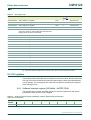
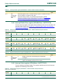
5.4.1 Software Interrupt register (VICSoftInt - 0xFFFF F018)
The contents of this register are ORed with the 32 interrupt requests from the various
peripherals, before any other logic is applied.
Table 34: Software Interrupt register (VICSoftInt - address 0xFFFF F018) bit allocation
Reset value: 0x0000 0000
Bit
31
30
29
28
27
26
25
24
Symbol
-
-
-
-
-
-
-
-
Access
R/W
R/W
R/W
R/W
R/W
R/W
R/W
R/W
© Koninklijke Philips Electronics N.V. 2005. All rights reserved.
User manual
Rev. 01 — 24 June 2005
50
UM10120
Philips Semiconductors
Volume 1
Bit
Chapter 5: VIC
23
22
21
20
19
18
17
16
Symbol
-
-
AD1
BOD
I2C1
AD0
EINT3
EINT2
Access
R/W
R/W
R/W
R/W
R/W
R/W
R/W
R/W
15
14
13
12
11
10
9
8
Symbol
EINT1
EINT0
RTC
PLL
SPI1/SSP
SPI0
I2C0
PWM0
Access
R/W
R/W
R/W
R/W
R/W
R/W
R/W
R/W
7
6
5
4
3
2
1
0
Symbol
UART1
UART0
TIMER1
TIMER0
ARMCore1
ARMCore0
-
WDT
Access
R/W
R/W
R/W
R/W
R/W
R/W
R/W
R/W
Bit
Bit
Table 35:
Software Interrupt register (VICSoftInt - address 0xFFFF F018) bit description
Bit
Symbol
Value
31:0
See VICSoftInt 0
bit allocation
table.
1
Description
Reset value
Do not force the interrupt request with this bit number. Writing
zeroes to bits in VICSoftInt has no effect, see VICSoftIntClear
(Section 5.4.2).
0
Force the interrupt request with this bit number.
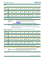
5.4.2 Software Interrupt Clear register (VICSoftIntClear - 0xFFFF F01C)
This register allows software to clear one or more bits in the Software Interrupt register,
without having to first read it.
Table 36: Software Interrupt Clear register (VICSoftIntClear - address 0xFFFF F01C) bit allocation
Reset value: 0x0000 0000
Bit
31
30
29
28
27
26
25
24
Symbol
-
-
-
-
-
-
-
-
Access
WO
WO
WO
WO
WO
WO
WO
WO
Bit
23
22
21
20
19
18
17
16
Symbol
-
-
AD1
BOD
I2C1
AD0
EINT3
EINT2
Access
WO
WO
WO
WO
WO
WO
WO
WO
Bit
15
14
13
12
11
10
9
8
Symbol
EINT1
EINT0
RTC
PLL
SPI1/SSP
SPI0
I2C0
PWM0
Access
WO
WO
WO
WO
WO
WO
WO
WO
7
6
5
4
3
2
1
0
Symbol
UART1
UART0
TIMER1
TIMER0
ARMCore1
ARMCore0
-
WDT
Access
WO
WO
WO
WO
WO
WO
WO
WO
Bit
Table 37:
Software Interrupt Clear register (VICSoftIntClear - address 0xFFFF F01C) bit description
Bit
Symbol
Value
31:0
See
0
VICSoftIntClea 1
r bit allocation
table.
Description
Reset
value
Writing a 0 leaves the corresponding bit in VICSoftInt unchanged.
0
Writing a 1 clears the corresponding bit in the Software Interrupt
register, thus releasing the forcing of this request.
© Koninklijke Philips Electronics N.V. 2005. All rights reserved.
User manual
Rev. 01 — 24 June 2005
51
UM10120
Philips Semiconductors
Volume 1
Chapter 5: VIC
5.4.3 Raw Interrupt status register (VICRawIntr - 0xFFFF F008)
This is a read only register. This register reads out the state of the 32 interrupt requests
and software interrupts, regardless of enabling or classification.
Table 38: Raw Interrupt status register (VICRawIntr - address 0xFFFF F008) bit allocation
Reset value: 0x0000 0000
Bit
31
30
29
28
27
26
25
24
Symbol
-
-
-
-
-
-
-
-
Access
RO
RO
RO
RO
RO
RO
RO
RO
Bit
23
22
21
20
19
18
17
16
Symbol
-
-
AD1
BOD
I2C1
AD0
EINT3
EINT2
Access
RO
RO
RO
RO
RO
RO
RO
RO
Bit
15
14
13
12
11
10
9
8
Symbol
EINT1
EINT0
RTC
PLL
SPI1/SSP
SPI0
I2C0
PWM0
Access
RO
RO
RO
RO
RO
RO
RO
RO
7
6
5
4
3
2
1
0
Symbol
UART1
UART0
TIMER1
TIMER0
ARMCore1
ARMCore0
-
WDT
Access
RO
RO
RO
RO
RO
RO
RO
RO
Bit
Table 39:
Raw Interrupt status register (VICRawIntr - address 0xFFFF F008) bit description
Bit
Symbol
Value
Description
Reset
value
31:0
See
VICRawIntr bit
allocation
table.
0
The interrupt request or software interrupt with this bit number is
negated.
0
1
The interrupt request or software interrupt with this bit number is
negated.
5.4.4 Interrupt Enable register (VICIntEnable - 0xFFFF F010)
This is a read/write accessible register. This register controls which of the 32 interrupt
requests and software interrupts contribute to FIQ or IRQ.
Table 40: Interrupt Enable register (VICIntEnable - address 0xFFFF F010) bit allocation
Reset value: 0x0000 0000
Bit
31
30
29
28
27
26
25
24
Symbol
-
-
-
-
-
-
-
-
Access
R/W
R/W
R/W
R/W
R/W
R/W
R/W
R/W
23
22
21
20
19
18
17
16
Symbol
-
-
AD1
BOD
I2C1
AD0
EINT3
EINT2
Access
R/W
R/W
R/W
R/W
R/W
R/W
R/W
R/W
Bit
Bit
15
14
13
12
11
10
9
8
Symbol
EINT1
EINT0
RTC
PLL
SPI1/SSP
SPI0
I2C0
PWM0
Access
R/W
R/W
R/W
R/W
R/W
R/W
R/W
R/W
7
6
5
4
3
2
1
0
Symbol
UART1
UART0
TIMER1
TIMER0
ARMCore1
ARMCore0
-
WDT
Access
R/W
R/W
R/W
R/W
R/W
R/W
R/W
R/W
Bit
© Koninklijke Philips Electronics N.V. 2005. All rights reserved.
User manual
Rev. 01 — 24 June 2005
52
UM10120
Philips Semiconductors
Volume 1
Table 41:
Chapter 5: VIC
Interrupt Enable register (VICIntEnable - address 0xFFFF F010) bit description
Bit
Symbol
Description
Reset
value
31:0
See
VICIntEnable
bit allocation
table.
When this register is read, 1s indicate interrupt requests or software interrupts
that are enabled to contribute to FIQ or IRQ.
0
When this register is written, ones enable interrupt requests or software
interrupts to contribute to FIQ or IRQ, zeroes have no effect. See Section 5.4.5
“Interrupt Enable Clear register (VICIntEnClear - 0xFFFF F014)” on page 53
and Table 43 below for how to disable interrupts.
5.4.5 Interrupt Enable Clear register (VICIntEnClear - 0xFFFF F014)
This is a write only register. This register allows software to clear one or more bits in the
Interrupt Enable register (see Section 5.4.4 “Interrupt Enable register (VICIntEnable 0xFFFF F010)” on page 52), without having to first read it.
Table 42: Software Interrupt Clear register (VICIntEnClear - address 0xFFFF F014) bit allocation
Reset value: 0x0000 0000
Bit
31
30
29
28
27
26
25
24
Symbol
-
-
-
-
-
-
-
-
Access
WO
WO
WO
WO
WO
WO
WO
WO
Bit
23
22
21
20
19
18
17
16
Symbol
-
-
AD1
BOD
I2C1
AD0
EINT3
EINT2
Access
WO
WO
WO
WO
WO
WO
WO
WO
Bit
15
14
13
12
11
10
9
8
Symbol
EINT1
EINT0
RTC
PLL
SPI1/SSP
SPI0
I2C0
PWM0
Access
WO
WO
WO
WO
WO
WO
WO
WO
7
6
5
4
3
2
1
0
Symbol
UART1
UART0
TIMER1
TIMER0
ARMCore1
ARMCore0
-
WDT
Access
WO
WO
WO
WO
WO
WO
WO
WO
Bit
Table 43:
Software Interrupt Clear register (VICIntEnClear - address 0xFFFF F014) bit description
Bit
Symbol
Value
Description
Reset
value
31:0
See
VICIntEnClear
bit allocation
table.
0
Writing a 0 leaves the corresponding bit in VICIntEnable
unchanged.
0
1
Writing a 1 clears the corresponding bit in the Interrupt Enable
register, thus disabling interrupts for this request.
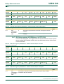
5.4.6 Interrupt Select register (VICIntSelect - 0xFFFF F00C)
This is a read/write accessible register. This register classifies each of the 32 interrupt
requests as contributing to FIQ or IRQ.
Table 44: Interrupt Select register (VICIntSelect - address 0xFFFF F00C) bit allocation
Reset value: 0x0000 0000
Bit
31
30
29
28
27
26
25
24
Symbol
-
-
-
-
-
-
-
-
Access
R/W
R/W
R/W
R/W
R/W
R/W
R/W
R/W
© Koninklijke Philips Electronics N.V. 2005. All rights reserved.
User manual
Rev. 01 — 24 June 2005
53
UM10120
Philips Semiconductors
Volume 1
Bit
Chapter 5: VIC
23
22
21
20
19
18
17
16
Symbol
-
-
AD1
BOD
I2C1
AD0
EINT3
EINT2
Access
R/W
R/W
R/W
R/W
R/W
R/W
R/W
R/W
15
14
13
12
11
10
9
8
Symbol
EINT1
EINT0
RTC
PLL
SPI1/SSP
SPI0
I2C0
PWM0
Access
R/W
R/W
R/W
R/W
R/W
R/W
R/W
R/W
7
6
5
4
3
2
1
0
Symbol
UART1
UART0
TIMER1
TIMER0
ARMCore1
ARMCore0
-
WDT
Access
R/W
R/W
R/W
R/W
R/W
R/W
R/W
R/W
Bit
Bit
Table 45:
Interrupt Select register (VICIntSelect - address 0xFFFF F00C) bit description
Bit
Symbol
Value
Description
Reset
value
31:0
See
VICIntSelect
bit allocation
table.
0
The interrupt request with this bit number is assigned to the IRQ
category.
0
1
The interrupt request with this bit number is assigned to the FIQ
category.
5.4.7 IRQ Status register (VICIRQStatus - 0xFFFF F000)
This is a read only register. This register reads out the state of those interrupt requests
that are enabled and classified as IRQ. It does not differentiate between vectored and
non-vectored IRQs.
Table 46: IRQ Status register (VICIRQStatus - address 0xFFFF F000) bit allocation
Reset value: 0x0000 0000
Bit
31
30
29
28
27
26
25
24
Symbol
-
-
-
-
-
-
-
-
Access
RO
RO
RO
RO
RO
RO
RO
RO
Bit
23
22
21
20
19
18
17
16
Symbol
-
-
AD1
BOD
I2C1
AD0
EINT3
EINT2
Access
RO
RO
RO
RO
RO
RO
RO
RO
Bit
15
14
13
12
11
10
9
8
Symbol
EINT1
EINT0
RTC
PLL
SPI1/SSP
SPI0
I2C0
PWM0
Access
RO
RO
RO
RO
RO
RO
RO
RO
7
6
5
4
3
2
1
0
Symbol
UART1
UART0
TIMER1
TIMER0
ARMCore1
ARMCore0
-
WDT
Access
RO
RO
RO
RO
RO
RO
RO
RO
Bit
Table 47:
IRQ Status register (VICIRQStatus - address 0xFFFF F000) bit description
Bit
Symbol
Description
Reset
value
31:0
See
VICIRQStatus
bit allocation
table.
A bit read as 1 indicates a coresponding interrupt request being enabled,
classified as IRQ, and asserted
0
© Koninklijke Philips Electronics N.V. 2005. All rights reserved.
User manual
Rev. 01 — 24 June 2005
54
UM10120
Philips Semiconductors
Volume 1
Chapter 5: VIC
5.4.8 FIQ Status register (VICFIQStatus - 0xFFFF F004)
This is a read only register. This register reads out the state of those interrupt requests
that are enabled and classified as FIQ. If more than one request is classified as FIQ, the
FIQ service routine can read this register to see which request(s) is (are) active.
Table 48: FIQ Status register (VICFIQStatus - address 0xFFFF F004) bit allocation
Reset value: 0x0000 0000
Bit
31
30
29
28
27
26
25
24
Symbol
-
-
-
-
-
-
-
-
Access
RO
RO
RO
RO
RO
RO
RO
RO
Bit
23
22
21
20
19
18
17
16
Symbol
-
-
AD1
BOD
I2C1
AD0
EINT3
EINT2
Access
RO
RO
RO
RO
RO
RO
RO
RO
Bit
15
14
13
12
11
10
9
8
Symbol
EINT1
EINT0
RTC
PLL
SPI1/SSP
SPI0
I2C0
PWM0
Access
RO
RO
RO
RO
RO
RO
RO
RO
7
6
5
4
3
2
1
0
Symbol
UART1
UART0
TIMER1
TIMER0
ARMCore1
ARMCore0
-
WDT
Access
RO
RO
RO
RO
RO
RO
RO
RO
Bit
Table 49:
FIQ Status register (VICFIQStatus - address 0xFFFF F004) bit description
Bit
Symbol
Description
Reset
value
31:0
See
VICFIQStatus
bit allocation
table.
A bit read as 1 indicates a coresponding interrupt request being enabled,
classified as IRQ, and asserted
0
5.4.9 Vector Control registers 0-15 (VICvectCntl0-15 - 0xFFFF F200-23C)
These are a read/write accessible registers. Each of these registers controls one of the 16
vectored IRQ slots. Slot 0 has the highest priority and slot 15 the lowest. Note that
disabling a vectored IRQ slot in one of the VICVectCntl registers does not disable the
interrupt itself, the interrupt is simply changed to the non-vectored form.
Table 50:
Vector Control registers 0-15 (VICvectCntl0-15 - 0xFFFF F200-23C) bit description
Bit
Symbol
Description
Reset
value
4:0
int_request/
sw_int_assig
The number of the interrupt request or software interrupt assigned to this
vectored IRQ slot. As a matter of good programming practice, software should
not assign the same interrupt number to more than one enabled vectored IRQ
slot. But if this does occur, the lowernumbered slot will be used when the
interrupt request or software interrupt is enabled, classified as IRQ, and
asserted.
0
5
IRQslot_en
When 1, this vectored IRQ slot is enabled, and can produce a unique ISR
address when its assigned interrupt request or software interrupt is enabled,
classified as IRQ, and asserted.
0
31:6
-
Reserved, user software should not write ones to reserved bits. The value read NA
from a reserved bit is not defined.
© Koninklijke Philips Electronics N.V. 2005. All rights reserved.
User manual
Rev. 01 — 24 June 2005
55
UM10120
Philips Semiconductors
Volume 1
Chapter 5: VIC
5.4.10 Vector Address registers 0-15 (VICVectAddr0-15 - 0xFFFF F100-13C)
These are a read/write accessible registers. These registers hold the addresses of the
Interrupt Service routines (ISRs) for the 16 vectored IRQ slots.
Table 51:
Vector Address registers (VICVectAddr0-15 - addresses 0xFFFF F100-13C) bit description
Bit
Symbol
Description
31:0
IRQ_vector
When one or more interrupt request or software interrupt is (are) enabled,
0x0000 0000
classified as IRQ, asserted, and assigned to an enabled vectored IRQ slot,
the value from this register for the highest-priority such slot will be provided
when the IRQ service routine reads the Vector Address register -VICVectAddr
(Section 5.4.10).
Reset value
5.4.11 Default Vector Address register (VICDefVectAddr - 0xFFFF F034)
This is a read/write accessible register. This register holds the address of the Interrupt
Service routine (ISR) for non-vectored IRQs.
Table 52:
Default Vector Address register (VICDefVectAddr - address 0xFFFF F034) bit description
Bit
Symbol
Description
Reset value
31:0
IRQ_vector
When an IRQ service routine reads the Vector Address register
0x0000 0000
(VICVectAddr), and no IRQ slot responds as described above, this address is
returned.
5.4.12 Vector Address register (VICVectAddr - 0xFFFF F030)
This is a read/write accessible register. When an IRQ interrupt occurs, the IRQ service
routine can read this register and jump to the value read.
Table 53:
Vector Address register (VICVectAddr - address 0xFFFF F030) bit description
Bit
Symbol
Description
31:0
IRQ_vector
If any of the interrupt requests or software interrupts that are assigned to a
0x0000 0000
vectored IRQ slot is (are) enabled, classified as IRQ, and asserted, reading
from this register returns the address in the Vector Address Register for the
highest-priority such slot (lowest-numbered) such slot. Otherwise it returns the
address in the Default Vector Address Register.
Reset value
Writing to this register does not set the value for future reads from it. Rather,
this register should be written near the end of an ISR, to update the priority
hardware.
5.4.13 Protection Enable register (VICProtection - 0xFFFF F020)
This is a read/write accessible register. This one-bit register controls access to the VIC
registers by software running in User mode.
Table 54:
Protection Enable register (VICProtection - address 0xFFFF F020) bit description
Bit
Symbol
Value
Description
Reset
value
0
VIC_access
0
VIC registers can be accessed in User or privileged mode.
0
1
The VIC registers can only be accessed in privileged mode.
31:1
-
Reserved, user software should not write ones to reserved bits. The NA
value read from a reserved bit is not defined.
© Koninklijke Philips Electronics N.V. 2005. All rights reserved.
User manual
Rev. 01 — 24 June 2005
56
UM10120
Philips Semiconductors
Volume 1
Chapter 5: VIC
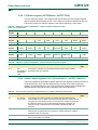
5.5 Interrupt sources
Table 55 lists the interrupt sources for each peripheral function. Each peripheral device
has one interrupt line connected to the Vectored Interrupt Controller, but may have several
internal interrupt flags. Individual interrupt flags may also represent more than one
interrupt source.
Table 55:
Connection of interrupt sources to the Vectored Interrupt Controller (VIC)
Block
Flag(s)
VIC Channel # and Hex
Mask
WDT
Watchdog Interrupt (WDINT)
0
0x0000 0001
-
Reserved for Software Interrupts only
1
0x0000 0002
ARM Core
Embedded ICE, DbgCommRx
2
0x0000 0004
ARM Core
Embedded ICE, DbgCommTX
3
0x0000 0008
TIMER0
Match 0 - 3 (MR0, MR1, MR2, MR3)
4
0x0000 0010
5
0x0000 0020
6
0x0000 0040
7
0x0000 0080
Capture 0 - 3 (CR0, CR1, CR2, CR3)
TIMER1
Match 0 - 3 (MR0, MR1, MR2, MR3)
Capture 0 - 3 (CR0, CR1, CR2, CR3)
UART0
Rx Line Status (RLS)
Transmit Holding Register Empty (THRE)
Rx Data Available (RDA)
Character Time-out Indicator (CTI)
UART1
Rx Line Status (RLS)
Transmit Holding Register Empty (THRE)
Rx Data Available (RDA)
Character Time-out Indicator (CTI)
Modem Status Interrupt (MSI)[1]
PWM0
Match 0 - 6 (MR0, MR1, MR2, MR3, MR4, MR5, MR6)
8
0x0000 0100
I2C0
SI (state change)
9
0x0000 0200
SPI0
SPI Interrupt Flag (SPIF)
10
0x0000 0400
11
0x0000 0800
Mode Fault (MODF)
SPI1 (SSP)
TX FIFO at least half empty (TXRIS)
Rx FIFO at least half full (RXRIS)
Receive Timeout condition (RTRIS)
Receive overrun (RORRIS)
PLL
PLL Lock (PLOCK)
12
0x0000 1000
RTC
Counter Increment (RTCCIF)
13
0x0000 2000
External Interrupt 0 (EINT0)
14
0x0000 4000
External Interrupt 1 (EINT1)
15
0x0000 8000
External Interrupt 2 (EINT2)
16
0x0001 0000
External Interrupt 3 (EINT3)
17
0x0002 0000
A/D Converter 0 end of conversion
18
0x0004 0000
Alarm (RTCALF)
System Control
ADC0
© Koninklijke Philips Electronics N.V. 2005. All rights reserved.
User manual
Rev. 01 — 24 June 2005
57
UM10120
Philips Semiconductors
Volume 1
Table 55:
Chapter 5: VIC
Connection of interrupt sources to the Vectored Interrupt Controller (VIC)
Block
Flag(s)
VIC Channel # and Hex
Mask
I2C1
SI (state change)
19
0x0008 0000
BOD
Brown Out detect
20
0x0010 0000
ADC1
A/D Converter 1 end of conversion[1]
21
0x0020 0000
[1]
LPC2134/6/8 Only.
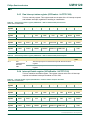
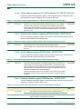
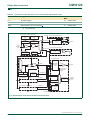
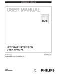
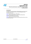
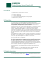
Interrupt request, masking and selection
SOFTINTCLEAR
[31:0]
INTENABLECLEAR
[31:0]
SOFTINT
[31:0]
INTENABLE
[31:0]
VICINT
SOURCE
[31:0]
nVICFIQIN
Non-vectored FIQ interrupt logic
FIQSTATUS[31:0]
FIQSTATUS
[31:0]
nVICFIQ
Non-vectored IRQ interrupt logic
IRQSTATUS[31:0]
RAWINTERRUPT
[31:0]
Vector interrupt 0
IRQSTATUS
[31:0]
INTSELECT
[31:0]
NonVectIRQ
IRQ
Priority 0
Interrupt priority logic
VECTIRQ0
HARDWARE
PRIORITY
LOGIC
IRQ
nVICIRQ
Address select for
highest priority
interrupt
SOURCE
ENABLE
VECTORCNTL[5:0]
Vector interrupt 1
VECTORADDR
[31:0]
Priority1
VECTADDR0[31:0]
VECTIRQ1
VECTORADDR
[31:0]
VECTADDR1[31:0]
VICVECT
ADDROUT
[31:0]
Priority2
Vector interrupt 15
Priority14
VECTIRQ15
DEFAULT
VECTORADDR
[31:0]
VECTADDR15[31:0]
Priority15
nVICIRQIN
VICVECTADDRIN[31:0]
Fig 14. Block diagram of the Vectored Interrupt Controller (VIC)
© Koninklijke Philips Electronics N.V. 2005. All rights reserved.
User manual
Rev. 01 — 24 June 2005
58
UM10120
Philips Semiconductors
Volume 1
Chapter 5: VIC
5.6 Spurious interrupts
Spurious interrupts are possible in the ARM7TDMI based microcontrollers such as the
LPC2131/2/4/6/8 due to asynchronous interrupt handling. The asynchronous character of
the interrupt processing has its roots in the interaction of the core and the VIC. If the VIC
state is changed between the moments when the core detects an interrupt, and the core
actually processes an interrupt, problems may be generated.
Real-life applications may experience the following scenarios:
1. VIC decides there is an IRQ interrupt and sends the IRQ signal to the core.
2. Core latches the IRQ state.
3. Processing continues for a few cycles due to pipelining.
4. Core loads IRQ address from VIC.
Furthermore, It is possible that the VIC state has changed during step 3. For example, VIC
was modified so that the interrupt that triggered the sequence starting with step 1) is no
longer pending -interrupt got disabled in the executed code. In this case, the VIC will not
be able to clearly identify the interrupt that generated the interrupt request, and as a result
the VIC will return the default interrupt VicDefVectAddr (0xFFFF F034).
This potentially disastrous chain of events can be prevented in two ways:
1. Application code should be set up in a way to prevent the spurious interrupts from
occurring. Simple guarding of changes to the VIC may not be enough since, for
example, glitches on level sensitive interrupts can also cause spurious interrupts.
2. VIC default handler should be set up and tested properly.
5.6.1 Details and case studies on spurious interrupts
This chapter contains details that can be obtained from the official ARM website
(http://www.arm.com), FAQ section under the "Technical Support" link:
http://www.arm.com/support/faqip/3677.html.
What happens if an interrupt occurs as it is being disabled?
Applies to: ARM7TDMI
If an interrupt is received by the core during execution of an instruction that disables
interrupts, the ARM7 family will still take the interrupt. This occurs for both IRQ and FIQ
interrupts.
For example, consider the following instruction sequence:
MRS r0, cpsr
ORR r0, r0, #I_Bit:OR:F_Bit
MSR cpsr_c, r0
;disable IRQ and FIQ interrupts
If an IRQ interrupt is received during execution of the MSR instruction, then the behavior
will be as follows:
• The IRQ interrupt is latched.
© Koninklijke Philips Electronics N.V. 2005. All rights reserved.
User manual
Rev. 01 — 24 June 2005
59
UM10120
Philips Semiconductors
Volume 1
Chapter 5: VIC
• The MSR cpsr, r0 executes to completion setting both the I bit and the F bit in the
CPSR.
• The IRQ interrupt is taken because the core was committed to taking the interrupt
exception before the I bit was set in the CPSR.
• The CPSR (with the I bit and F bit set) is moved to the SPSR_IRQ.
This means that, on entry to the IRQ interrupt service routine, you can see the unusual
effect that an IRQ interrupt has just been taken while the I bit in the SPSR is set. In the
example above, the F bit will also be set in both the CPSR and SPSR. This means that
FIQs are disabled upon entry to the IRQ service routine, and will remain so until explicitly
re-enabled. FIQs will not be reenabled automatically by the IRQ return sequence.
Although the example shows both IRQ and FIQ interrupts being disabled, similar behavior
occurs when only one of the two interrupt types is being disabled. The fact that the core
processes the IRQ after completion of the MSR instruction which disables IRQs does not
normally cause a problem, since an interrupt arriving just one cycle earlier would be
expected to be taken. When the interrupt routine returns with an instruction like:
SUBS pc, lr, #4
the SPSR_IRQ is restored to the CPSR. The CPSR will now have the I bit and F bit set,
and therefore execution will continue with all interrupts disabled. However, this can cause
problems in the following cases:
Problem 1: A particular routine maybe called as an IRQ handler, or as a regular
subroutine. In the latter case, the system guarantees that IRQs would have been disabled
prior to the routine being called. The routine exploits this restriction to determine how it
was called (by examining the I bit of the SPSR), and returns using the appropriate
instruction. If the routine is entered due to an IRQ being received during execution of the
MSR instruction which disables IRQs, then the I bit in the SPSR will be set. The routine
would therefore assume that it could not have been entered via an IRQ.
Problem 2: FIQs and IRQs are both disabled by the same write to the CPSR. In this case,
if an IRQ is received during the CPSR write, FIQs will be disabled for the execution time of
the IRQ handler. This may not be acceptable in a system where FIQs must not be
disabled for more than a few cycles.
5.6.2 Workaround
There are 3 suggested workarounds. Which of these is most applicable will depend upon
the requirements of the particular system.
5.6.3 Solution 1: test for an IRQ received during a write to disable IRQs
Add code similar to the following at the start of the interrupt routine.
SUB
STMFD
MRS
TST
LDMNEFD
lr, lr, #4
sp!, {..., lr}
lr, SPSR
lr, #I_Bit
sp!, {..., pc}^
;
;
;
;
;
;
;
Adjust LR to point to return
Get some free regs
See if we got an interrupt while
interrupts were disabled.
If so, just return immediately.
The interrupt will remain pending since we haven’t
acknowledged it and will be reissued when interrupts
© Koninklijke Philips Electronics N.V. 2005. All rights reserved.
User manual
Rev. 01 — 24 June 2005
60
UM10120
Philips Semiconductors
Volume 1
Chapter 5: VIC
; are next enabled.
; Rest of interrupt routine
This code will test for the situation where the IRQ was received during a write to disable
IRQs. If this is the case, the code returns immediately - resulting in the IRQ not being
acknowledged (cleared), and further IRQs being disabled.
Similar code may also be applied to the FIQ handler, in order to resolve the first issue.
This is the recommended workaround, as it overcomes both problems mentioned above.
However, in the case of problem two, it does add several cycles to the maximum length of
time FIQs will be disabled.
5.6.4 Solution 2: disable IRQs and FIQs using separate writes to the CPSR
MRS
ORR
MSR
ORR
MSR
r0, cpsr
r0, r0, #I_Bit
cpsr_c, r0
r0, r0, #F_Bit
cpsr_c, r0
;disable IRQs
;disable FIQs
This is the best workaround where the maximum time for which FIQs are disabled is
critical (it does not increase this time at all). However, it does not solve problem one, and
requires extra instructions at every point where IRQs and FIQs are disabled together.
5.6.5 Solution 3: re-enable FIQs at the beginning of the IRQ handler
As the required state of all bits in the c field of the CPSR are known, this can be most
efficiently be achieved by writing an immediate value to CPSR_C, for example:
MSR cpsr_c, #I_Bit:OR:irq_MODE
;IRQ should be disabled
;FIQ enabled
;ARM state, IRQ mode
This requires only the IRQ handler to be modified, and FIQs may be re-enabled more
quickly than by using workaround 1. However, this should only be used if the system can
guarantee that FIQs are never disabled while IRQs are enabled. It does not address
problem one.
5.7 VIC usage notes
If user code is running from an on-chip RAM and an application uses interrupts, interrupt
vectors must be re-mapped to on-chip address 0x0. This is necessary because all the
exception vectors are located at addresses 0x0 and above. This is easily achieved by
configuring the MEMMAP register (see Section 3.6.1 “Memory Mapping control register
(MEMMAP - 0xE01F C040)” on page 25) to User RAM mode. Application code should be
linked such that at 0x4000 0000 the Interrupt Vector Table (IVT) will reside.
Although multiple sources can be selected (VICIntSelect) to generate FIQ request, only
one interrupt service routine should be dedicated to service all available/present FIQ
request(s). Therefore, if more than one interrupt sources are classified as FIQ the FIQ
interrupt service routine must read VICFIQStatus to decide based on this content what to
© Koninklijke Philips Electronics N.V. 2005. All rights reserved.
User manual
Rev. 01 — 24 June 2005
61
UM10120
Philips Semiconductors
Volume 1
Chapter 5: VIC
do and how to process the interrupt request. However, it is recommended that only one
interrupt source should be classified as FIQ. Classifying more than one interrupt sources
as FIQ will increase the interrupt latency.
Following the completion of the desired interrupt service routine, clearing of the interrupt
flag on the peripheral level will propagate to corresponding bits in VIC registers
(VICRawIntr, VICFIQStatus and VICIRQStatus). Also, before the next interrupt can be
serviced, it is necessary that write is performed into the VICVectAddr register before the
return from interrupt is executed. This write will clear the respective interrupt flag in the
internal interrupt priority hardware.
In order to disable the interrupt at the VIC you need to clear corresponding bit in the
VICIntEnClr register, which in turn clears the related bit in the VICIntEnable register. This
also applies to the VICSoftInt and VICSoftIntClear in which VICSoftIntClear will clear the
respective bits in VICSoftInt. For example, if VICSoftInt = 0x0000 0005 and bit 0 has to be
cleared, VICSoftIntClear = 0x0000 0001 will accomplish this. Before the new clear
operation on the same bit in VICSoftInt using writing into VICSoftIntClear is performed in
the future, VICSoftIntClear = 0x0000 0000 must be assigned. Therefore writing 1 to any
bit in Clear register will have one-time-effect in the destination register.
If the watchdog is enabled for interrupt on underflow or invalid feed sequence only then
there is no way of clearing the interrupt. The only way you could perform return from
interrupt is by disabling the interrupt at the VIC (using VICIntEnClr).
Example:
Assuming that UART0 and SPI0 are generating interrupt requests that are classified as
vectored IRQs (UART0 being on the higher level than SPI0), while UART1 and I2C are
generating non-vectored IRQs, the following could be one possibility for VIC setup:
VICIntSelect = 0x0000 0000
VICIntEnable = 0x0000 06C0
VICDefVectAddr = 0x...
VICVectAddr0 = 0x...
VICVectAddr1 = 0x...
VICVectCntl0 = 0x0000 0026
VICVectCntl1 = 0x0000 002A
; SPI0, I2C, UART1 and UART0 are IRQ =>
; bit10, bit9, bit7 and bit6=0
; SPI0, I2C, UART1 and UART0 are enabled interrupts =>
; bit10, bit9, bit 7 and bit6=1
; holds address at what routine for servicing
; non-vectored IRQs (i.e. UART1 and I2C) starts
; holds address where UART0 IRQ service routine starts
; holds address where SPI0 IRQ service routine starts
; interrupt source with index 6 (UART0) is enabled as
; the one with priority 0 (the highest)
; interrupt source with index 10 (SPI0) is enabled
; as the one with priority 1
After any of IRQ requests (SPI0, I2C, UART0 or UART1) is made, microcontroller will
redirect code execution to the address specified at location 0x0000 0018. For vectored
and non-vectored IRQ’s the following instruction could be placed at 0x0000 0018:
LDR pc, [pc,#-0xFF0]
This instruction loads PC with the address that is present in VICVectAddr register.
© Koninklijke Philips Electronics N.V. 2005. All rights reserved.
User manual
Rev. 01 — 24 June 2005
62
UM10120
Philips Semiconductors
Volume 1
Chapter 5: VIC
In case UART0 request has been made, VICVectAddr will be identical to VICVectAddr0,
while in case SPI0 request has been made value from VICVectAddr1 will be found here. If
neither UART0 nor SPI0 have generated IRQ request but UART1 and/or I2C were the
reason, content of VICVectAddr will be identical to VICDefVectAddr.
© Koninklijke Philips Electronics N.V. 2005. All rights reserved.
User manual
Rev. 01 — 24 June 2005
63