1
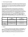
ECF-1 User Manual P/N 3910 kit does not include flex fuel sensor. The ECF-1 is compatible with GM P/Ns 13577429 and 13577379 1. Flex Fuel and Lambda ............................................................................. 2 2. ECF-1 ....................................................................................................... 2 1.1 Changing the ECF-1’s gauge face and/or bezel ............................. 4 Installation ................................................................................................ 5 2.1 Wiring............................................................................................... 5 2.1.1 Single Innovate Device Relay Wiring Instructions ....................... 6 2.2 Gauge Mounting and Routing ......................................................... 7 2.3 Wideband Oxygen Sensor Setup .................................................... 7 2.3.1 Oxygen Sensor Placement .......................................................... 7 2.3.2 Sensor Calibration ....................................................................... 8 2.3.3 Calibration Schedule ................................................................... 9 2.4 Flex Fuel Sensor ........................................................................... 10 2.4.1 Flex Fuel Sensor Wiring ............................................................ 10 2.5 Fuel Pressure Sensor .................................................................... 10 2.5.1 Fuel Pressure Sensor Wiring .................................................... 11 Gauge Setup Options ............................................................................. 11 3.1 Entering Setup Configuration ........................................................ 11 3.1.1 Configuration using ECF-1’s interface buttons .......................... 11 3.1.2 Configuration using the LM Programmer software .................... 11 3.2 Display Settings (Gauge Abbreviations)........................................ 12 Logworks 3 & LM Programmer Software Package ................................ 12 4.1 Download and Install the Logworks 3 Software ............................ 13 4.2 LM Programmer............................................................................. 13 4.2.1 Programming Analog Outputs ................................................... 13 4.2.2 Advanced Analog Output Programming (Wideband) ................ 14 4.2.3 Updating the Firmware .............................................................. 14 4.2.4 Changing Sensor Type .............................................................. 15 4.3 Logging data from your ECF-1 with LogWorks ............................. 15 Appendix A: Limited Warranty ....................................................................... 17 Appendix B: ECF-1 Error Codes and Troubleshooting Tips ......................... 18 11-0145 1. Flex Fuel and Lambda Even though E85 is assumed to be 85% ethanol and 15% gasoline, the true blend can vary significantly from one fuel fill up to another. This of course has to be taken into account in the tune, especially in high performance ethanol fueled applications. It is for this reason that it is important to not only monitor the ethanol content percentage, but also measure the air/fuel values with different blends. When measuring air/fuel ratio in a flex fuel system, it is important to understand that different fuels have different stoichiometric values and therefore different scales. This can greatly affect how the values are interpreted. As seen in the table below, the stoichiometric value and the display scale for each fuel differs. Since the blend of ethanol is ever changing so will the relative stoichiometric value. The easiest solution to interpreting the changing stoichiometric values is to use lambda (λ) as the unit of measure instead of air/fuel ratio. The stoichiometric value in lambda is 1 regardless of the fuel type. It is for this reason that the ECF-1 comes set from the factory displaying lambda. This is a user definable option, meaning the ECF-1 can also be programed to display AFR for nearly any fuel type. Fuel Type Gasoline Ethanol E85 (85% ethanol, 15% gasoline) Stoichiometric A/F Ratio (Display Range) 14.7 (7.35 AFR to 22.4 AFR) Stoichiometric Lambda Value (Display Range) 1 (.5 λ to 1.5 λ) 9.0 (4.5 AFR to 13.5 AFR) 9.8 (4.9 AFR to 14.7 AFR) 1 (.5 λ to 1.5 λ) 1 (.5 λ to 1.5 λ) 2. ECF-1 The ECF-1 is a four-in-one, ethanol content %, fuel temperature, fuel pressure, and wideband air/fuel ratio gauge. Although it can be operated stand alone, it has digital I/O for integration with other Innovate Motorsports MTS compatible products and four configurable analog outputs for integration with piggy back or stand-alone ECU’s as well as external data loggers. The following section will help you get familiar with the ECF-1. 2 1. Channel Display - The ECF-1 has three different displays modes that can be cycled through on the main screen with the left and right interface buttons. The channels being displayed in the single and dual channel displays are user defined from the setup menu. 2. Status or Error display - When in the single or dual channel display, the upper right hand viewport of the ECF-1 is reserved to display any O2 sensor or flex fuel sensor error codes that might be present. 3. Interface Buttons - Pressing either the left or right interface buttons will allow you to cycle through the 3 different display modes. - From the main screen, pressing and HOLDING the left interface button will put the gauge in setup mode. Once in setup mode, pressing and HOLDING both interface buttons together will move you to the menu or main screen. The gauge will revert back to the main screen if no there have been no button presses for 15 seconds. 4. Warning Light - Illuminates when the low fuel pressure warning is triggered. 3 1.1 Changing the ECF-1’s gauge face and/or bezel 1. Lay the ECF-1 face down and remove the three #2 phillips screws from the outside rim of the back plate. 2. 3. Configure the gauge as desired by changing the gauge face and/or bezel. 4. Make sure every piece is positioned correctly using the locating tab and reassemble the gauge. 5. Reinstall the three #2 phillips screws verifying that the buttons are not binding on the gauge lens. 4 Installation 2.1 Wiring The ECF-1 has 7 stripped wire leads: 1 Connect the RED wire to an isolated switched 12V source in your vehicle. A switched 12V source goes ON as soon as “key on” power is active. The circuit to which you will pull power from should be able to support a 3 amp draw. Make sure this connection is protected with a 5A fuse (not supplied.) Circuits that share power with the vehicle’s stereo, ignition system, ECU, lighting, or fuel pump should not be used. When in doubt, create an additional circuit using an automotive relay available at any automotive parts supplier. See the next section for a relay installation diagram. 2 The BLACK wire should be grounded to a solid ground source. The best possible ground source would be the battery ground (-) post. If other Innovate Motorsports devices are going to be daisy-chained along with the ECF-1, it is recommended that all devices be connected to a single ground point, ideally the battery ground (-) post. 3 Connect the WHITE wire to a headlight power wire (a wire that goes hot with 12V when the headlights are on)). This enables the display to dim for better nighttime viewing. DO NOT CONNECT THIS WIRE TO THE HEADLIGHT DIMMING WIRE. Connection to this rheostat type of switch will cause the gauge to malfunction. If you chose not to utilize the dimming feature, connect the WHITE wire to ground. 4 Optionally, the YELLOW (Wideband), BROWN (Ethanol %), ORANGE (Fuel Temp), and/or PINK (Fuel Pressure) analog outputs can be connected to the analog inputs of other devices such as data loggers or 5 programmable ECUs. If any of these wires are not being used, isolate and tape the wire(s) out of the way. The analog outputs are linear and fully programmable with the LM Programmer software. The factory default analog outputs are as follows: Wire Color Yellow Channel Min Max Wideband Brown Orange Pink Ethanol % Fuel Temp Fuel Pressure 0V = 7.35 (Gasoline) 0V = 0% Ethanol 0V = -40 degF 0V = 0 PSI 5V = 22.39 (Gasoline) 5V = 100% Ethanol 5V = 257 degF 5V = 145 PSI It is assumed that the ECF-1 and the device the analog output is being feed to are already sharing the same ‘ground’. In a vehicle, this is generally true, but there can be small offsets in voltage when devices are grounded to,the chassis at different points. You can minimize these offsets by sharing a good, common ground point. 2.1.1 Single Innovate Device Relay Wiring Instructions 6 Gauge Mounting and Routing 2.2 The ECF-1 gauge fits in any standard 2 1/16” (52mm) gauge pod. Mounting of the gauge should be done in such a manner that the cables are not being forcefully pulled and strained from the gauge itself. Route the sensor cables avoiding contact with the exhaust system and other vehicle components that could damage the cable. Also avoid routing the cables near ignition components or other sources of RF (radio frequency) and EMI (Electromagnetic interference) noise. Wideband Oxygen Sensor Setup 2.3 2.3.1 Oxygen Sensor Placement Optimum bung placement will vary from application to application, but using the guidelines below will ensure the longest sensor life with the most accurate readings. Using a bung is the preferred method for mounting the oxygen sensor in all applications. Weld the bung at least 24 inches downstream of the exhaust port outlet (after the collector), or 24 inches after the turbocharger if so equipped. The bung should be welded before the X or H pipe if so equipped. Using a clock as reference, mount the bung between the 9:00 o’clock and 3:00 o’clock position. Welding the bung in the lower section of the exhaust pipe can result in sensor damage caused by condensation making contact with the sensor’s internal heating element. A 1” bung (provided in the kit) will best protect the sensor. When fully threaded, the sensor’s tip will sit flush with the exhaust pipe, this does not adversely affect the readings. The bung should always be welded before the Catalytic Converter. Welding the bung after the catalytic converter will skew the readings toward lean. The skew in readings will vary with engine load and the efficiency of the catalytic converter. Leaded fuel and two stroke applications will reduce the sensor’s life. There are many other factors that dictate the sensor’s lifespan so it is impossible to predict its total longevity. Exhaust leaks, camshaft overlap, and open (shorty) exhausts will cause false lean readings at light engine loads. Typically, once the 7 engine is under load and the exhaust gas volume increases, you will see accurate readings. When installed in the exhaust, the oxygen sensor must be connected to a powered, functional ECF-1 (no error codes) whenever the engine is running. An un-powered sensor will be damaged in a short period of time when exposed to exhaust gas. Do not pre-warm the sensor before starting the engine, simply start the engine as normal. Allowing the sensor to pre-warm before starting the engine will increase the possibility of damaging the sensor from shock-cooling. The maximum temperature of the sensor at the bung (the sensor mounting location) should not exceed 500 oC or 900 oF. If these temperatures are exceeded in your application you should install the Innovate Motorsports HBX-1 heat sink bung extender. (p/n 3729.) As the O2 sensor measures the oxygen content of the exhaust gas to provide an accurate O2 reading, even a small pin-hole leak in a poorly welded sensor bung will effect the accuracy and performance of your O2 sensor. Remember, any deviation from the instructions provided for proper sensor installation will lead to inaccurate O2 readings. 2.3.2 Sensor Calibration Once the unit has been wired and a suitable location has been found for both the gauge and the sensor it is time to perform the sensor calibration. Innovate Motorsports’ ‘Direct Digital’ wideband measurement principal allows you to calibrate the sensor to compensate for sensor wear. This procedure takes just a few moments and it will ensure the most accurate readings throughout the oxygen sensor’s life. This procedure is required anytime a NEW oxygen sensor is installed. The calibration procedure requires that the oxygen sensor be in free air, this means removed from the exhaust system completely. 1. With the sensor disconnected, apply power to the ECF-1. Confirm that the wideband channel displays “O2 E2.” This is an error code, indicating that no sensor is detected. Leave unit powered on for a minimum of 30 seconds. 2. Power down the ECF-1 and attach the oxygen sensor using the cable provided. When making these connections, make sure they are fully 8 seated and locked. Again, make sure that the sensor is in free air (not in the exhaust). 3. Power up the ECF-1. The ECF-1 will start warming up the sensor, this is indicated the display by showing “O2 HTR.” After 30-60 seconds, the display will switch from “O2 HTR” and quickly flash “O2 CAL”, indicating that the sensor is being calibrated. The calibration procedure has completed and the system is now ready for use. Important: You can disconnect and reconnect the sensor and sensor cable for installation without losing your calibration. However, if you power up the ECF-1 without a sensor connected, your calibration will be reset (see step #1 above). 2.3.3 Calibration Schedule Normally aspirated (daily driver) - Calibrate before installation of new sensor - Calibrate new sensor again after 3 month of use - Thereafter calibrate once a year or every 20,000 miles, whichever comes first Turbo Application, daily driver (tuned rich) - Calibrate before installation of new sensor - Calibrate new sensor again after 3 month of use - Thereafter calibrate twice a year or every 10,000 miles, whichever comes first Race Application - Calibrate before first installation of new sensor - Calibrate once per race weekend 9 Flex Fuel Sensor 2.4 P/N 3910 kit does not include flex fuel sensor. The ECF-1 is compatible with GM P/Ns 13577429 and 13577379 The installation of the flex fuel sensor requires knowledge of the fuel system. Improper installation can lead to catastrophic failure, and damage to vehicle and/or persons. It is highly recommend that the flex fuel sensor be installed by a reputable professional mechanic. 2.4.1 The flex fuel sensor will report both ethanol content and fuel temperature. The sensor fittings are 3/8" SAE quick-disconnect male on both ends. Plan for the flex fuel sensor installation. Additional fuel hose and adapters (not included) might be necessary to successfully install the sensor. The sensor can be installed in the feed or return line. Because of possible fuel restrictions, installation of the sensor in the return line might be the best choice. Before disconnecting any fuel line connections make sure to depressurize the fuel system. The orientation of the flex fuel sensor is not important, it can be mounted in any direction. Check for fuel leaks and address them accordingly before driving the vehicle! Flex Fuel Sensor Wiring 1. Fish the flex fuel sensor’s 4 pin connector cable through the firewall, to the ECF-1 gauge. Make sure to leave enough strain relief. 2. Connect the sensor’s female 4 pin connector to the male 4 pin connector on the gauge. 3. Connect the Delphi 3 pin connector to the flex fuel sensor. 2.5 Fuel Pressure Sensor To ease installation, the gauge kit includes an in-line adapter to mount the fuel pressure sensor along with the flex fuel sensor. If this adapter is going to be used, the Flex Fuel sensor must be installed in the feed line of the fuel system. The fuel pressure sensor can be mounted onto any 1/8 27 NPT port. 10 2.5.1 Before disconnecting any fuel line connections make sure to depressurize the fuel system. Check for fuel leaks and address them accordingly before driving the vehicle! Fuel Pressure Sensor Wiring 1. Fish the fuel pressure sensor’s 3 pin connector through the firewall, to the ECF-1 gauge. Make sure to leave enough strain relief. 2. Connect the sensor’s female 3 pin connector to the male 3 pin connector on the gauge. 3. Lastly, connect the AMP 3 pin connector to the fuel pressure sensor. Gauge Setup Options 3.1 Entering Setup Configuration The ECF-1 can be configured directly from the gauge itself or by connecting it to a computer with the LM Programmer software. 3.1.1 Configuration using ECF-1’s interface buttons 1. From the main screen, press and HOLD the left interface button to put the gauge in setup mode 2. Pressing either the left or right interface buttons will allow you to cycle through the 9 different setup parameters in the menu. 3. Once the desired setup parameter is displayed, press and HOLD the left interface button to make a change. Once the parameter’s configuration has been entered it will start flashing. 4. Make changes by using the left or right interface buttons. 5. Once in setup mode, pressing and HOLDING both interface buttons together will move you to the menu or main screen. The gauge will revert back to the main screen if no there have been no button presses for 15 seconds. 3.1.2 Configuration using the LM Programmer software Refer to chapter 4, Logworks 3 & LM Programmer Software Package to gain access to the software. 1. Connect the OUT port of the ECF-1 to the provided serial programming cable. Connect the other end of the serial programming cable to your computer. If your computer does not have a serial port, you can purchase a USB to Serial adapter from 11 Innovate Motorsports (P/N 3733) or use any USB to serial adaptor that includes drivers. Make sure that nothing is connected to the IN port of the ECF-1 2. Power up the ECF-1. 3. Launch LM Programmer. The LM Programmer application can be launched from Start->Programs->LogWorks3->LM Programmer from the Windows task bar. Once you have completed your desired changes, press the Program button on the lower right on the software application. You will know that the ECF-1 has been programmed successfully when the Program button grays out. 3.2 Display Settings (Gauge Abbreviations) 1. Fuel Pressure Alarm (Low Press Alarm) – Set the minimum fuel pressure reading to trigger the warning light. 2. Fuel Temperature Units (Temp Units) – Set the unit of measure for the fuel temperature channel to either Fahrenheit or Celsius. Default setting is Fahrenheit. 3. Fuel Pressure Units (Press Units) - Allows the gauge to display fuel pressure in either PSIor BAR. Default setting is PSI. 4. Wideband O2 Units (WB O2 Units) – Allows the gauge to display O2 units in either AFR or Lambda. Default setting is AFR. 5. Sensor Type to use (WB O2 State) – This option can only be changed in LM Programmer, refer to chapter “Changing Sensor Type.” The gauge will display the current sensor type being used. Default is LSU 4.9. 6. Fuel Type – Change to different fuel types when the ECF-1 is setup to display in AFR. Default setting is Gasoline. 7. Single Field Screen (Single Screen) – Chose which channel is displayed in the single channel display. Default setting is Wideband. 8. Dual Field Screen (Dual Screen LG and SM) – Chose which channel is displayed as the primary and secondary channel in the dual channel screen. Default setting is Fuel Pressure for the primary and Ethanol % for the secondary display. Logworks 3 & LM Programmer Software Package The ECF-1 can be connected directly to your Windows computer to log and analyze data with the Logworks software or to configure with LM Programmer. The software is a free download on the Innovate Motorsports’ support section of the website. 12 4.1 Download and Install the Logworks 3 Software 1. Open your web browser and go to the following URL: http://www.innovatemotorsports.com/support.php 2. The LogWorks 3 software download will be the very first thing on the page under the heading Software, click the link to download the software. 3. Double click on the Logworks 3 installer previously downloaded from the support section of the Innovate Motorsports web site. 4. The installer will start, follow the prompts to install the software. 5. Once the software has been installed, the LogWorks software, LM Programmer, manuals, and tools can then be located by navigating through Start->Programs->LogWorks3. 4.2 LM Programmer LM Programmer is used to configure settings on your ECF-1. 1. Connect the OUT port of the ECF-1 to the provided serial programming cable. Connect the other end of the serial programming cable to your computer. If your computer does not have a serial port, you can purchase a USB to Serial adapter from Innovate Motorsports (P/N 3733) or use any USB to serial adaptor that includes drivers. Make sure that nothing is connected to the IN port of the ECF-1 2. Power up the ECF-1. 3. Launch LM Programmer. The LM Programmer application can be launched from Start->Programs->LogWorks3->LM Programmer from the Windows task bar. 4.2.1 Programming Analog Outputs The ECF-1 has individual analog outputs for each one of its channels: A/F, Ethanol %, Fuel temperature, and Fuel Pressure. Each one of the analog outputs can be programmed to a custom linear scale. Connect the ECF-1 to the computer and launch LM Programmer. Select the analog output tab which is going to be modified. The analog output configuration screen shows voltage versus channel for the analog output. The graph display is automatically scaled to the selected values. The configuration screen allows the user to specify a minimum and maximum and channel values to a corresponding voltage range. Click the ‘Program’ button to upload your modified analog output data into the ECF-1. Once the unit has been programmed, the ‘Program’ button will grey out. 13 Factory Programmed Default: 4.2.2 Wire Color Yellow Channel Min Max Wideband Brown Orange Pink Ethanol % Fuel Temp Fuel Pressure 0V = 7.35 (Gasoline) 0V = 0% Ethanol 0V = -40 degF 0V = 0 PSI 5V = 22.39 (Gasoline) 5V = 100% Ethanol 5V = 257 degF 5V = 145 PSI Advanced Analog Output Programming (Wideband) The ‘Advanced’ button allows the user to set the analog out update speed and the voltage output during sensor Warm-up and error conditions. The factory defaults of the analog outputs update 1/12 of a second. The default voltage output is set at 0 volts for both the Warm-up and error conditions. When setting the ECF-1 to the slower response speed settings, the measured mixture data will be averaged over the response time setting before being sent via the analog output. 4.2.3 Updating the Firmware Do not update the firmware if the versions are the same. A firmware update should only be necessary if there has been a new release that specifically fixes a problem that you are experiencing with the controller. 1. Connect the ECF-1 to the computer and launch LM Programmer. 2. Once connected, LM Programmer will display the current version of the firmware that is installed in the ECF-1. Do not flash the firmware if the versions are the same. 3. On the ‘Info’ tab of LM Programmer you will see a button labeled “Update Firmware,” click this button. 4. Select the firmware file with the dld extension. If there have been revisions to the firmware, you will find them available for download from the Support section of the Innovate Motorsports web site. 5. The software will now prompt you to confirm that you wish to overwrite the firmware currently on your ECF-1. 6. Click OK, the gauge of the ECF-1 will go blank. DO NOT power off or disconnect the ECF-1 from the computer until the firmware progress screen completely disappears. Once finished, you may disconnect the unit from the computer and exit out of the software. 14 4.2.4 Changing Sensor Type Note: The ECF-1 must be running firmware version 1.08 or later with LM Programmer 4.0 or later to access the sensor type menu. The ECF-1 is multi sensor compatible with the Bosch LSU 4.2 and 4.9 sensors. In order to go from one sensor type to another the ECF-1 must be connected to the LM Programmer software and the appropriate sensor type must be selected. The “Sensor Type to use” setting can be found in the ‘Info’ tab when LM Programmer connects to the ECF-1. Once the sensor type is changed a sensor calibration must be performed with the sensor outside of the exhaust (see Sensor Calibration chapter.) Sensor Cable P/N LSU 4.2 LSU 4.9 3ft 8ft 18ft 3843 3810 3828 3890 3887 3889 Sensor P/N LSU 4.2 3737 LSU 4.9 3888 Note: All sensor cables for the LSU 4.9 are easily identified by a ‘4.9’ marking molded on the sensor connector side. Use the appropriate sensor cable for the sensor type as each sensor has a different style connector. Spliced cable will not only affect the wideband’s performance but in worst cases it can damage the sensor and/or controller. Selecting the wrong sensor type to the sensor being used will not only give you erroneous readings and/or errors. It can also permanently damage the sensor. 4.3 Logging data from your ECF-1 with LogWorks 1. Connect the OUT port of the ECF-1 to the provided serial programming cable. Connect the other end of the serial programming cable to your computer. If your computer does not have a serial port, you can purchase a USB to Serial adapter from Innovate Motorsports (P/N 3733) or use any USB to serial adaptor that includes drivers. Make sure that nothing is connected to the IN port of the ECF-1. Power up the ECF-1. 2. Launch LogWorks. The LogWorks application can be launched from Start->Programs->LogWorks3->Logworks3 from the Windows task bar. 15 3. Once LogWorks launches go to File->Connect. You will be prompted to connect to the serial COM port. Select the COM port the device is connected to and then click Connect. 4. You will now see live data streaming from the ECF-1. 5. To start recording go to File->New Real-time Log or, in the Toolbar, click on the Tool. . 16 Appendix A: Limited Warranty LIMITED WARRANTY Innovate stands behind the quality of its products. Innovate makes the following warranty to purchasers of its products: All new Innovate products carry a one year warranty from the date of purchase. If proof of purchase cannot be provided, warranty will be determined by date of manufacture. When Warranty Void This warranty shall terminate and Innovate shall have no obligation pursuant to it if (i) your Innovate product has been modified or repaired in a manner not previously authorized by Innovate in writing, (ii) the identification markings on your Innovate product have been removed, defaced, or altered; (iii) your Innovate product was subjected to accident, abuse, shipping damage, or improper use; (iv) your Innovate product was not used or configured as specified in the product manual; or (v) your Innovate product was subjected to operating conditions more severe than those specified in the product manual. Exclusions From This Warranty Oxygen Sensors are excluded from this warranty. Repairs Under This Warranty In the unlikely event that your Innovate hardware product should prove defective during the warranty period, contact Innovate Customer Support at http://www.innovatemotorsports.com/rma_form.php for a return material authorization (RMA). Products returned for service must be securely packed to prevent damage and shipped charges pre paid, along with proof of purchase and the return material authorization number, to the Innovate repair location as instructed by Customer Service. Innovate within a reasonable amount of time from its receipt of your product so shipped, will ship to you, at its option, the repaired product or a new or reconditioned product of comparable or greater specified functionality. All repaired or replacement products shall be warranted for the remainder of the original product warranty. Disclaimer INNOVATE MAKES NO OTHER EXPRESS OR IMPLIED WARRANTY WITH RESPECT TO YOUR INNOVATE PRODUCT OTHER THAN THE LIMITED WARRANTY SET FORTH ABOVE. No Innovate dealer, agent, or employee is authorized to make any modification, extension, or addition to this warranty, unless enforceable or unlawful under applicable law, INNOVATE DISCLAIMS ALL IMPLIED WARRANTIES, INCLUDING THE IMPLIED WARRANTIES OF MERCHANTABILITY, NONINFRINGEMENT, AND FITNESS FOR A PARTICULAR PURPOSE, AND THE LIABILITY OF INNOVATE, IF ANY, FOR DAMAGES RELATING TO ANY ALLEGEDLY DEFECTIVE PRODUCT SHALL UNDER ANY TORT, CONTRACT, OR OTHER LEGAL THEORY BE LIMITED TO THE ACTUAL PRICE PAID FOR SUCH PRODUCT AND SHALL IN NO EVENT INCLUDE INCIDENTAL, CONSEQUENTIAL, SPECIAL, OR INDIRECT DAMAGES OF ANY KIND EVEN IF INNOVATE IS AWARE OF THE POSSIBILITY OF SUCH DAMAGES. Some states do not allow limitations on how long an implied warranty lasts or the exclusion or limitation of incidental or consequential damages, so the above limitations or exclusions may not apply to you. 17 Appendix B: ECF-1 Error Codes and Troubleshooting Tips Error Code Error 1 Error 2 Error Message Likely Root Cause Fix Heater circuit shorted Heater circuit open Short in sensor Replace sensor. 1. Verify that all sensor connectors are fully seated and locked into position. 2. Replace sensor 3. Replace sensor cable. 1. Replace sensor cable. 2. Replace sensor. 3. Perform sensor recalibration. Error 3 Pump cell circuit shorted Error 4 Pump cell circuit open Error 5 Reference cell circuit shorted Reference cell circuit open 1. Damaged sensor cable or sensor. 2. Sensor connector not fully seated and locked into position. 1. Short in sensor cable 2. Short in sensor 3. Sensor calibration incorrect 1. Damaged sensor cable or sensor. 2. Connectors not fully seated 3. Sensor calibration incorrect 1. Short in sensor cable 2. Short in sensor 1. Damaged sensor cable or sensor. Error 7 Error 8 System error Sensor Timing error (typically a damaged sensor). 2. Connectors not fully seated System error 1. Sensor over-heating or over-cooling (error condition only occurs at wide open throttle ) Error 9 Supply Voltage too low 2. Sensor is damaged Supply voltage too low for sensor regulation Error 6 Flex Fuel Sensor Error Codes E10 Flex Fuel sensor not connected E11 Fuel contamination or fuel over temperature 1. Verify that all sensor connectors are fully seated and locked into position. 2. Perform sensor calibration 3. Replace sensor cable. 4. Replace sensor. 1. Replace sensor cable. 2. Replace sensor. 1. Verify that all sensor connectors are fully seated and locked into position. 2. Replace sensor. 3. Replace sensor cable. Reboot ECF-1 by cycling power 1. Perform sensor calibration. 2. Move sensor bung as far downstream as possible. 3. Add an HBX-1 (p/n 3729) to isolate the sensor from the pipe. 4. Replace sensor. 1. Verify you have 12V at your power source and the circuit can support a 3 amp draw. 1. Verify that the connection at both the gauge and the sensor is fully seated and secured. 2. Check the integrity of the interface cable between the flex fuel sensor and gauge. 1. Fuel contamination. For example, water in fuel. 2. Fuel is above the max temp of 257 degF. 18