1
User’s Manual
Version 4.7.6
May 1, 2007
Important Notice
General Disclaimer
The contents of this document are subject to change without notice; therefore, the
information presented herein shall not be construed as a commitment or warranty.
Dynamis Corporation, Inc. shall not be liable for any technical or editorial errors or
omissions contained herein or for incidental or consequential damages resulting from the
performance, furnishing, reliance on, or use of this material. Figure 3-36 missing
Patents
Certain equipment and software described in this document is protected by issued and
pending U.S. and foreign patents.
All products and services are trademarks or registered trademarks of their respective
manufacturer.
Copyright
This document contains confidential and proprietary information protected by
copyright. Copyright © Dynamis Corporation, all rights reserved. Copying or other
reproduction of all or parts of this document is prohibited.
i
Table of Contents
1.
S Y S T E M O V E R V I E W ................................................................................. 1
Overview........................................................................................................................................ 1
Theory of Operation................................................................................................................... 1
Incoming Digits ......................................................................................................................... 1
Outgoing Digits.......................................................................................................................... 1
Software and Hardware Components ............................................................................................ 2
Host Computer ........................................................................................................................... 2
Remote Computer ...................................................................................................................... 2
EXS Switch................................................................................................................................ 2
Host Software............................................................................................................................. 2
Switch Software ......................................................................................................................... 2
What’s New: 2006-7, Version 4.7+ ............................................................................................... 4
Major Routing Enhancements.................................................................................................... 4
Major Translation Enhancements .............................................................................................. 4
XNET ONE Hardware Support ................................................................................................. 4
ISDN NI 2 Support .................................................................................................................... 4
Improved Backup and Restore................................................................................................... 4
Support for Large Digit Tables .................................................................................................. 5
Enhanced Billing Capabilities.................................................................................................... 5
Easy Upgrade ............................................................................................................................. 5
What’s New: 2004-5 ..................................................................................................................... 6
SS7 Route Advance ................................................................................................................... 6
Integrate SS7 CPN with Smart Long Distance Application ...................................................... 6
Configure Resource Group with CIP and TNS.......................................................................... 6
Automatic Call Distribution....................................................................................................... 7
Play ANI 900 Prompt to Conference Bridge ............................................................................. 7
Enhanced VRU Branding .......................................................................................................... 7
Least Cost Routing Using Digit Table Importing...................................................................... 7
Others......................................................................................................................................... 7
System Management Concepts ...................................................................................................... 8
Equipment Screens..................................................................................................................... 8
Resource Group and Route List Configuration Tables.............................................................. 8
Time of Day (TOD) Routing ..................................................................................................... 8
Automatic Call Distribution (ACD) Queues.............................................................................. 9
Digit Tables................................................................................................................................ 9
System Files and Records .......................................................................................................... 9
Data Files ................................................................................................................................... 9
Log Files .................................................................................................................................... 9
System Files ............................................................................................................................... 9
E2E Files.................................................................................................................................... 9
ii
2.
S Y S T E M A D M I N ...................................................................................... 10
Overview...................................................................................................................................... 10
Starting the Software.................................................................................................................... 11
Password Management Screen .................................................................................................... 14
User Attributes screen.............................................................................................................. 15
System Setup Screen.................................................................................................................... 17
Switch Setup screen ................................................................................................................. 21
Alarm Setup screen .................................................................................................................. 22
Redundancy setup screen......................................................................................................... 23
Note: It is recommended that you NOT use this feature. .................................................... 24
Application Server Link screen ............................................................................................... 25
Node Setup screen.................................................................................................................... 26
Software Download ..................................................................................................................... 27
Backing up System Related Files ................................................................................................ 31
3.
M O N I T O R I N G E Q U I P M E N T ....................................................................... 35
Introduction.................................................................................................................................. 35
Equipment List............................................................................................................................. 35
Card-related icons .................................................................................................................... 35
Power Supply Card ...................................................................................................................... 42
Updating card status................................................................................................................. 44
Midplane ...................................................................................................................................... 45
Fan Tray ....................................................................................................................................... 47
DSP Card ..................................................................................................................................... 49
Putting SIMM into service....................................................................................................... 52
Putting SIMM out of service.................................................................................................... 52
Configuring DSPs .................................................................................................................... 52
T1 Card ........................................................................................................................................ 56
Updating card status................................................................................................................. 61
Querying Fault Log.................................................................................................................. 61
Clearing Fault Log ................................................................................................................... 61
Putting T1 card in service ........................................................................................................ 61
Putting T1 card out of service.................................................................................................. 61
Returning T1 card to active status ........................................................................................... 62
E1 Card ........................................................................................................................................ 63
Updating card status................................................................................................................. 67
Querying Fault Log.................................................................................................................. 67
Clearing Fault Log ................................................................................................................... 67
Putting E1 card in service ........................................................................................................ 68
Putting E1 card out of service.................................................................................................. 68
Returning E1 card to active status ........................................................................................... 68
EX/CPU Card............................................................................................................................... 69
Updating Card Status ............................................................................................................... 72
Querying Fault Log.................................................................................................................. 72
Clearing Fault Log ................................................................................................................... 72
Setting Switch Time................................................................................................................. 73
ISDN PRI Card ............................................................................................................................ 74
ISDN Offline Configuration – New to 2007............................................................................ 74
iii
Putting ISDN PRI card in service ............................................................................................ 78
Putting ISDN PRI card out of service...................................................................................... 78
Making ISDN PRI cards non- redundant................................................................................. 78
Making ISDN PRI cards redundant ......................................................................................... 78
SS7 Card ...................................................................................................................................... 80
Putting SS7 card in service ...................................................................................................... 84
Putting SS7 card out of service................................................................................................ 84
Making SS7 cards non-redundant............................................................................................ 84
Making SS7 cards redundant ................................................................................................... 85
Reconfiguring SS7 ................................................................................................................... 85
EXNET Controller card ............................................................................................................... 86
Updating card status................................................................................................................. 89
Querying Fault Log.................................................................................................................. 89
Clearing Fault Log ................................................................................................................... 89
Putting EXNET Controller card in service .............................................................................. 89
Putting EXNET Controller card out of service........................................................................ 89
Configuring EXNET ring ........................................................................................................ 89
Updating EXNET ring status ................................................................................................... 91
Updating EXNET ring status ................................................................................................... 93
Putting EXNET ring in service ................................................................................................ 93
Putting EXNET ring out of service.......................................................................................... 93
Reconfiguring the EXNET ring ............................................................................................... 93
4. C O N F IG U R I N G C H A N N E L S , R O U T E S & T R A N S L A T I O N S ................................. 94
Introduction.................................................................................................................................. 94
CONFIGURATION SEQUENCE FOR ROUTING & TRANSLATION.................................. 94
STEP 1: Configure and Put T1/E1/ISDN/SS7 Channels Into Service .................................... 94
STEP 2: Group Outbound Channels Into Resource Groups.................................................... 94
STEP 3: Build Inbound Pre-Translation Tables (Optional)..................................................... 94
STEP 4: Build ANI Validation & Index Tables (Optional)..................................................... 94
STEP 5: Build the NPA Table for Inter/Intra State Determination (Optional)........................ 95
STEP 6: Build Master Route Table for NPA/NXX Routing (Optional) ................................. 95
STEP 7: Assign Channel Features ........................................................................................... 95
STEP 8: Set up Time of Day Routing (Optional) .................................................................... 95
STEP 9: Create ACD Queues (Optional)................................................................................. 95
STEP 10: Create Post Routing Rules (Optional) ..................................................................... 95
STEP 11: Assign Resource Groups to Route Lists.................................................................. 95
STEP 12: Build Digit Tables ................................................................................................... 95
CALL CONTROL DIAGRAMS............................................................................................. 96
T1: Configuring & Putting T1 Channels in Service .................................................................... 98
Channels in T1 Spans............................................................................................................... 98
Activating a T1 Span ............................................................................................................... 98
Giving attributes to T1 channels ............................................................................................ 103
Viewing attributes of all T1 channels .................................................................................... 106
Changing reception filters...................................................................................................... 107
Changing reception timers ..................................................................................................... 108
Changing transmission timers................................................................................................ 110
E1: Configuring & Putting E1 Channels into Service ............................................................... 112
iv
Activating an E1 span ............................................................................................................ 112
Viewing E1 span attributes .................................................................................................... 116
Giving attributes to E1 channels ............................................................................................ 117
Viewing attributes of all E1 Channels ................................................................................... 120
ISDN: Configuring and Putting ISDN PRI Channels Into Service ........................................... 121
Assigning attributes to D Channel ......................................................................................... 122
NFAS: Associating D Channel with up to 10 T1 Spans..................................................... 125
Backing up NFAS group’s D Channel................................................................................... 127
Assigning attributes to B Channels........................................................................................ 128
Viewing attributes of all ISDN B Channels........................................................................... 131
ISDN Cause Code Routing .................................................................................................... 132
VRU Cause Code Prompt ...................................................................................................... 133
SS7: Configuring and Putting SS7 Channels into Service ........................................................ 134
Procedure ............................................................................................................................... 134
Creating SS7 Stacks............................................................................................................... 135
Creating SS7 Link Sets .......................................................................................................... 138
Configuring SS7 Links .......................................................................................................... 140
Creating SS7 Network Routes ............................................................................................... 143
Creating CICs for SS7 Channels............................................................................................ 146
Creating SS7 Cause Code Routing ........................................................................................ 160
VRU Cause Code Prompt ...................................................................................................... 161
Resource Groups - Grouping Channels ..................................................................................... 162
Dragging & dropping channels/CICs into a resource group.................................................. 163
Changing hunt order .............................................................................................................. 163
Exporting and Importing Resource Group Configuration ..................................................... 164
Assigning attributes to a resource group................................................................................ 165
Pre-Translation Tables ............................................................................................................... 170
ANI Tables for ANI/Code Validation........................................................................................ 174
Index Tables for ANI/Code Validation...................................................................................... 177
The NPA Table for Inter/Intra State Determination .................................................................. 180
The Master Route Table for NPA/NXX Routing ...................................................................... 181
Displaying only NPA/NXXs with entries.............................................................................. 183
Inter/Intra State Routing Menu .............................................................................................. 184
Channel Features - Assigning Features to Channels.................................................................. 186
Overview – New Features...................................................................................................... 186
Configuration ......................................................................................................................... 186
Viewing features for all channels .......................................................................................... 192
Time of Day / Day of Week Routing.........................................................................................193
ACD Queues .............................................................................................................................. 195
Post Routing Options ................................................................................................................. 199
Adding/Changing Post Routing Tables ................................................................................. 199
Post Routing Options Setup ................................................................................................... 200
Post Routing Options Translations ........................................................................................ 201
Calling Party Post Routing Options....................................................................................... 201
Called Party Post Routing Options ........................................................................................ 202
Assigning Post Routing to a Route List’s Resource Group................................................... 203
Route Lists to Create Alternate Routing for Calls ..................................................................... 205
Assigning resource groups to route list.................................................................................. 205
v
Dragging-and-dropping resource groups into a route list ...................................................... 207
Exporting Route List Configuration ...................................................................................... 208
Importing Route List Configuration ...................................................................................... 208
Assigning Post Routing to a Route List’s Resource Group................................................... 208
Digit Tables................................................................................................................................ 210
Overview – New for 2007...................................................................................................... 210
Creating a digit table.............................................................................................................. 211
Adding digit lookup entries to a digit table ........................................................................... 212
Viewing all digit lookup entries in a Digit Table .................................................................. 220
Find Route for a Specific Destination Number...................................................................... 221
Exporting Digit Table Configuration..................................................................................... 223
Least Cost Routing................................................................................................................. 223
Importing Digit Table Configuration..................................................................................... 223
VRU Branding ........................................................................................................................... 225
5. M A I N T E N A N C E ...................................................................................... 228
Overview.................................................................................................................................... 228
Switch Status screen .................................................................................................................. 228
Alarms screen............................................................................................................................. 232
Span and Channel Status screen ................................................................................................ 237
Viewing Span and Channel Status......................................................................................... 238
Selecting Channels................................................................................................................. 238
Placing Channels in Service................................................................................................... 239
Placing Channels Out of Service ........................................................................................... 239
Placing Entire Span in Service............................................................................................... 239
Placing Entire Span Out of Service ....................................................................................... 240
Query Channel Status screen ..................................................................................................... 240
Refresh Rate screen.................................................................................................................... 242
Changing Default Refresh Rate ............................................................................................. 242
Span Error Monitor screen......................................................................................................... 243
Carrier Answer Query................................................................................................................ 245
View Details........................................................................................................................... 246
Raw Command screen ............................................................................................................... 247
Warning.................................................................................................................................. 247
Switch Debug Log menu ........................................................................................................... 249
Opening Switch Log .............................................................................................................. 249
Closing Switch Log................................................................................................................ 249
Deleting Switch Log .............................................................................................................. 249
Viewing Switch Log .............................................................................................................. 249
Network Debug Log menu..................................................................................................... 250
System Update menu ................................................................................................................. 251
Apply Configuration .............................................................................................................. 251
Transferring files.................................................................................................................... 251
Forcing Switchover................................................................................................................ 251
A PPENDIX A: I NCOMING T YPES .......................................................................... 1
Overview........................................................................................................................................ 1
Valid T1 Incoming Types .............................................................................................................. 2
vi
Valid E1 Incoming Types .............................................................................................................. 3
Incoming Types not presently supported....................................................................................... 3
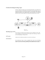
Tandem Switching Incoming Types .............................................................................................. 4
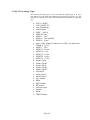
Incoming Types List ...................................................................................................................... 4
A P P E N D IX B: O U T G O I N G T Y P E S ..................................................................... 1
Overview.................................................................................................................................... 1
Outgoing Types List .................................................................................................................. 1
A P P E N D IX C: C O M P L E T I O N T Y P E S .................................................................. 1
Overview.................................................................................................................................... 1
Completion Type List ................................................................................................................ 1
A P P E N D IX D: A U T O M A T I C C A L L D I S T R I B U T I O N (ACD) E V E N T L O G F O R M A T S .... 1
Sample ACD Event Log ............................................................................................................ 1
ACD Event Log Descriptions .................................................................................................... 1
vii
1. System Overview
Overview
The E2 Eagle II Host Software (“Host”), combined with an EXS Switch, allows for a
highly flexible user programmable switching system. The EXS Switch allows you to
determine how you want to route the traffic. The Host provides call control and a
Graphical User Interface (GUI) that enables you to create routing applications quickly
and easily.
Theory of Operation
The Host is a call control system that uses a digit matching process of dialed digits.
The main components of the Host include an EXS Switch and the Host. The Host and
EXS Switch communicate via API (Application Programming Interface) messages.
The way the Host works is the EXS Switch receives the incoming digits (in most
cases, the ANI/CLI and dialed number). The Host is informed that digits have been
received, and processes the digits based on how they are configured in the various tables
within the Host. The Host sends the outgoing digits to the EXS Switch and the call is
routed to the called party (the dialed number).
Each Host is unique since it is configured on how you want to receive the incoming
digits and send the outgoing digits.
Incoming Digits
The digits/signals sent by the telco are recognized in the Host by the incoming type. The
incoming type defines the signaling protocol used on the incoming calls for a
particular trunk, and consists of incoming rules and inseize control instructions.
Incoming rules define the digit collection method and inseize control instructions
define the signaling used.
Incoming types supported in the Host include DTMF, DNIS, ANI, Feature Group D, and
Auto Terminating, to name a few. They are described in detail in Appendix A.
Outgoing Digits
After the digits are received, they must be configured for signaling and outpulsing to the
far end on an outgoing call. The completion type and ANI/CLI handle this process.
Completion types supported in the Host include Busy, Reorder, Ringing, Feature
Group D, and Music on Hold, to name a few. They are described in detail in
Appendices B and C.
Page 1
Software and Hardware Components
There are various hardware and software components which comprise the basic Call
Processing System. The hardware components include the Host Computer and the
EXS Switch. The Host Computer houses the Host Software and Switch Software (the
operating system of the EXS Switch). The switch houses the equipment items (line or
service resource cards) installed in the card slots. The equipment items are controlled
by the Host Software.
Host Computer
The Host Computer is a PC on which the Host Software, providing call control, is
installed. The Host Computer is also where the E2START.TXT file and E2 executable,
data, log, and system files are stored.
Remote Computer
The E2 Eagle GUI should be run on a separate remote computer, and NOT on the
same computer as the host. Otherwise, performance of the host computer may
degrade.
EXS Switch
The Excel family of switches is non-blocking digital systems with high density and
Digital Signal Processing (DSP) technology. The switches accommodate standard
telephone network and line interfaces, including T1, ISDN Primary Rate Interface
(ISDN RI), E1, and SS7.
Host Software
The Host Software controls the EXS Switch. The Host provides various functions such
as basic call processing, automatic call distribution, file maintenance, alarm logging
and reporting, backup and restore facilities, operator services, and remote access.
Switch Software
The Switch Software is the operating system of the EXS Switch. The Switch Software
is resident on the Host Computer and is downloaded to the EXS Switch.
Page 2
SYSTEM OVERVIEW
The E2 Eagle Host is multi-tasking with real time programming capabilities, enabling
you to configure, make changes, and add trunks and program new applications without
disrupting in-service applications. The Host is not an applications generator. The Host
is a call control system that allows you to create applications simply by programming
routing tables and translation tables within the system.
All generic call processing functions are available and maintained by the Host.
Programming screens are table/menu driven which create routing applications with ease.
Configuration tables are saved in the system and used whenever the need occurs.
The Host provides automatic boot startup (pre-programmed), cold startup (the
hardware must be powered off or restarted before startup), and warm startup (the
hardware can remain operational).
Some additional features of the Host include:
•
Supports fully redundant operations with the switch in the event of a CPU/
Matrix or host failure.
•
Utilizes multi-tasking with real time programming capabilities.
•
Provides many types of call control capabilities.
•
Translates digits received from the incoming calls as required.
•
Provides basic and enhanced call processing such as ACD (Automatic Call
Distribution), Least Cost Routing, and Time of Day Routing.
•
Uses an Application Programming Interface (API) over an Ethernet network
for seamless integration with database applications. Several pre-packaged
database applications such as Smart Calling Card (a.k.a. TAC, for Total Access
Card), Smart Callback (a.k.a. International Callback), and Smart Long
Distance (a.k.a. as ANI/PIN) integrate with E2 for delivery and management
of enhanced services.
•
Offers an open, flexible API for implementing new, enhanced services
applications. The message set allows database access and call processing
decisions external from the Host.
•
Uses multiple network protocols that allow you to build call processing
applications. Several types of call routing capabilities are available in the
Host. Basic call routing uses a digit matching process on incoming dialed
digits. Dialed digits are collected by means of incoming parameters and
Inseize Control. The Host supports DTMF, MFR1, and MFR2 digit collection
and generation as well as ISDN PRI D-Channel signaling.
•
Provides a digit match operation that points each incoming call to a Route
List. The Route List can be a Time of Day route. Each Route List can contain
up to 20 Resource Groups. Digit translations are available for both "called"
ANI and "calling party digits" received on the incoming call. Digits can be
added, changed, or deleted from the match.
Page 3
What’s New: 2006-7, Version 4.7+
The following are enhancements made since the previous major releases in 2004 and
2005. Enhancements include:
Major Routing Enhancements
The E2 Host has been significantly enhanced to support advanced routing, including:
•
Intrastate and Interstate least cost routing is supported, either based on the
combination NPAs of the ANI/Dialed Number or DNIS/Dialed Number.
•
Intra- and Inter-LATA least cost routing by (NPA_NXX) is supported by using a
Master Routing Table to handle all combinations of NPA and NXX.
•
Routing can be based on DNIS or ANI, as an alternative to the dialed number, or
in addition to it, as routing may be directed to multiple tables
•
Routing based on ISDN cause codes, including route advance, and route to a VRU
to play a message
•
Routing can be specified on the inbound channel basis, including routing by ANI,
DNIS, destination number, inter-/intra-state routing, and/or account code billing
by ANI
Major Translation Enhancements
Outbound translations, previously limited to primary and secondary translations, are
now virtually unlimited. This is due to Post-Routing Options in the Resource Groups,
and the fact that digit tables can point to other digit tables based on ANI, DNIS or
dialed number, before finally selecting the outbound Resource Groups.
Translation may also be configurable by inbound port, due to the addition of PreTranslation Tables associated with Feature Groups, and that Feature Groups may
specify the appropriate Digit Table or Master Routing Table, based on ANI, DNIS, or
Inter/Intra State.
XNET ONE Hardware Support
The E2 Host supports the one card Cantata Excel XNET-1 CPU card
ISDN NI 2 Support
Refer to NI 2 Configuration for details
Improved Backup and Restore
Virtually all configuration tables can be exported and imported, except for card
configuration.
Page 4
Support for Large Digit Tables
The digit table import process is improved to efficiently import large digit tables
quickly. i.e. 20,000 records in less than 2 minutes instead of over an hour with earlier
versions. In addition, a status screen displays to show progress and identify errors
Enhanced Billing Capabilities
The system has been enhanced to support tandem and postpaid billing capabilities
without needing the server software:
•
ANI Tables can configured, by ANI, either requiring a PIN for validation (using
Index Tables) , or requiring a non-validated PIN for billing purposes only.
•
Default ANI and/or DNIS can be specified when none is provided. This allows
for billing and tracking in these cases, especially used for FXS & FXO lines, and
VoIP billing for third-world countries.
•
Time Synchonization for Hosts. One can easily set the active and standby hosts to
the system date, thus synchronizing their time, essential for accurate billing during
switchover.
•
CDR fields have been extended for more complete billing records.
Easy Upgrade
The system is set up so it can easily import data from any older version to the new
version.
Page 5
What’s New: 2004-5
This was the first significant rewrite of the Host Software since the 1999 version of
ADS. Enhancements include:
SS7 Route Advance
When the system attempts an outgoing call via SS7, if the call fails, the system can
perform any of the following based upon the cause code returned:
•
Next available route – The next Resource Group will be used in the Route
List. If the last Resource Group has been used, the incoming trunk is released
with the Out Going trunk’s return cause code.
•
Play Busy Tone – The incoming trunk is play 10 cycles of busy tone before
the trunk is released.
•
Play Reorder Tone – The incoming trunk is play 10 cycles of reorder tone
before the trunk is released.
•
Release with Cause – The incoming trunk is release with the user define
cause code.
•
Route to VRU – The incoming trunk is routed to associated VRU SS7
Branding Route List. If the SS7 VRU Branding is not configured, the
incoming trunk is released with the Out Going trunk’s return cause code.
•
If the cause code number is not in the list, a second out going attempt is
made. After the second out dial attempt is made, the incoming trunk is
released with the Out Going trunk’s return cause code.
Refer to “SS7 Cause Code Setup” for details.
Integrate SS7 CPN with Smart Long Distance Application
The SS7 Calling Party Number (CPN) can now be used for billing and is integrated
with the Smart Long Distance Application Server. This corresponds to the billing
capabilities for the ANI/CLI of callers using ISDN and/or Channel Associated
Signaling (CAS).
Refer to the “Use SS7 for charge number for CPN” and the Channel Features,
Network List, SS7 Verify fields for details.
Configure Resource Group with CIP and TNS
The user can configure the Resource Group with the Carrier Identification Parameter.
(CIP) and Transit Network Selection (TNS). Refer to Resource Groups, Channel
Attributes, SS7 Parameters, and Figure 4-43 (Cause Code Routing screen) for details.
Page 6
One Click Span in/out of service
The user can take a Span in/out of service from the Span – Channel State window with
one click of a button.
Automatic Call Distribution
Automatic Call Distribution has been enhanced (Refer to “ACD Queues” for details).
Play ANI 900 Prompt to Conference Bridge
This gives you the capability of playing an announcement before entering a conference
bridge. If this box is checked, and under Options, VRU Branding, the prompt
configuration is set, the prompt will play.
Enhanced VRU Branding
VRU Branding is now more easily managed and more extensive (Refer to VRU
Branding for details).
Least Cost Routing Using Digit Table Importing
Digit Table Importing is a very powerful feature. For example, some people use a
spreadsheet listing a dozen or more carriers and their rates, which runs a macro that
creates a .CSV file that specifies least cost routing to the cheapest three carriers. As
rates change or new carriers are added, they simply rerun the macro and import the
new file. For more details, contact your E2 Eagle technical representative.
Others
•
The Stage II digit file can hold 30 entries
•
SS7 support for the latest signaling codes and cards
•
Incoming Type FGB AMA has been added
•
Digit table options now include 108 Test Number for loopback test to telcos, and
SMR to handle that type of mobile calling.
•
The digit table now includes a field for comments of up to 64 characters, which
can be imported and exported
Page 7
System Management Concepts
The telephone connection resource of the hardware switching system is commonly
referred to as a trunk. When using the Host, each trunk in the switching equipment is
composed of a span ID and a channel ID.
A span is a telephone facility containing a number of channels assigned to each T1/ E1
line card (24 channels in T1 spans, 30 in E1 spans) in the EXS Switch.
A Span ID is referred to as a Logical Span ID and must be assigned to properly
perform any configuration, routing, or call processing. All references to the trunks in the
system are identified by span and channel, with the span being the Logical ID.
The key to the processing of calls is the interaction of tables that are created in the
system. Tables provide the interaction between the equipment, software, and
application. The following are examples of some of the more important features in the
System.
Equipment Screens
The use of the term "equipment" in this section relates to the cards installed in the
switch. The Host provides configuration screens for the following cards:
•
•
•
•
•
E1
SDN
MFDSP
SS7
T1
Each card installed in the EXS Switch is recognized by the Host. The Host presents a
configuration screen for each card. The Host queries the switch during initial power up
and constructs an equipment list showing each piece of installed equipment. By
selecting a card from the list, the detailed information about that card is displayed on
the screen. It is from this screen that Logical Span IDs, Service Circuit, and ISDN
information is configured. The Logical ID assignment is critical to all other tables
because it associates spans and channels to physical circuits.
Resource Group and Route List Configuration Tables
You can specify how each trunk (span and channel) in the system operates. Individual
tables include Trunk Types, Trunk Features, Query Timers, and Digit Tables, each
presenting a unique screen. When the E1 option is added to the Host, an additional
category is displayed for configuring the E1 trunks.
The Resource Group and Route List tables are created to form hunting and trunk
selection methods for routing outgoing calls. A Resource Group can be a single trunk or
a group of trunks (up to 48 T1/60 E1 trunks).
Time of Day (TOD) Routing
Time of Day routing is used to change Resource Group choices based on time of day
and day of week. The routes can be used to provide least cost routing or other
applications requiring time or day sensitive routing. Up to 35 entries are allowed for
each TOD route.
Page 8
Automatic Call Distribution (ACD) Queues
Routing capabilities using ACD Queues is a standard feature of the Host and can
provide many enhancements to call processing. ACD Queues are designed to provide
automatic even call distribution between trunks or stations in a Resource Group. The
distribution of the calls is based on the time each trunk has been busy. This feature
also includes timed overflow, queue sizing, queue full routing, and overflow routing.
Digit Tables
Basic call routing uses a digit matching process of dialed digits. The collected digits are
looked up in the Digit Tables for a match. The Digit Table provides the Route List
pointer for outgoing calls, such as a unique table assigned to the trunk for the duration
of the call. Digit translations are available for digits received on the incoming call.
Digits can be added, changed, or deleted from the match. A successful match points
to a Route List for outgoing trunk selection.
System Files and Records
All configuration information is stored on the Host Computer. This information is
presented in the form of data files, log files, system files, and E2E Files.
Data Files
Data files contain user-definable information relating to digit tables, exclusion tables,
Resource Groups, route lists, TOD groups, client applications, etc.
Log Files
Log files are created and used by the Host to log various functions and events. The
information recorded in the log files includes critical errors, alarms, operator events, etc.
System Files
The system files are created and updated by the Host to store various system
information such as login passwords, country codes, CIC codes, redundancy files, ISDN
channels, board status messages, cable IDs, etc.
E2E Files
The E2E files are created and updated by the Host. These files contain information such
as startup messages for all tasks, operator menus and prompts, call completion types,
incoming start dial, disk copy text errors, etc.
Page 9
2. System Admin
Overview
This chapter describes how to setup system specific information such as password
security, EXS Switch configuration, and software management. Using the System
Admin menu options, you can:
•
Change the name, password, or security privilege of a user.
•
Add a user to the system.
•
Delete a user from the system.
•
Select the desired method of Call Detail Record output.
•
Specify the number of days in which the system will automatically delete the
oldest CDR files.
•
Configure the ACD event record output.
•
Select a communications port that allows an active Host to communicate with
a second Host acting as a standby.
•
Select a TCP/IP port or log file to output alarm messages.
•
Configure an Excel Server data link.
•
Configure up to eight VRU links.
•
Download Programmable Protocol Language (PPL) files that establish
signaling variations if you have E1 facilities.
•
Download a new or existing version of the System Software (Dynamis'
operating system) to the Matrix CPU card.
•
Download the LICENSE.CFG file to the EXS Switch.
•
Send raw configuration commands to the EXS Switch.
Page 10
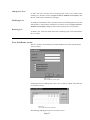
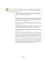
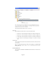
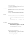
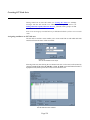
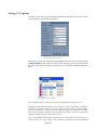
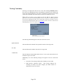
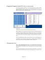
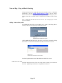
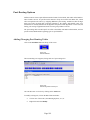
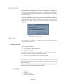
Starting the Software
Launching the Host
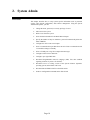
The E2 Host Software should always be running on the Host system. When running,
there should be a screen like the following displayed, or it should be minimized and an
icon appears in the taskbar entitled “E2 Host.”
Figure 2-1
E2 Host Software, sample screen and icon in taskbar
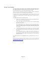
If the host software is NOT running, then click on the “E2 Host” icon to
begin:
Figure 2-2
E2 Host Icon for launching host
Page 11
Launching the E2 GUI
The E2 GUI should be launched on a separate computer from the E2 Host. Click
on the “E2 GUI” icon to begin:
Figure 2-3
E2 GUI Icon
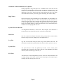
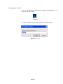
You will be prompted to enter the name or IP address of the host computer:
Figure 2-4
Name/IP Address Screen
Page 12
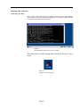
The E2 Eagle launch screen will then appear:
Figure 2-5
E2 Launching Screen
Then you will be prompted to login by entering your Name and Password:
Figure 2-6
Login Screen
At this point, the main E2 GUI menu will appear:
Figure 2-7
E2 GUI Main Menu
Page 13
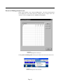
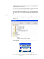
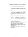
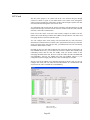
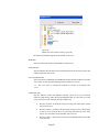
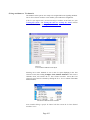
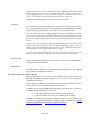
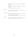
Password Management Screen
Under “System Admin”, select “Password Management”. The Password Management
screen displays the user names and access privileges that you assign in the User
Attributes screen (see Figure 2-3 User Attributes screen layout).
Figure 2-8
Password Management screen layout
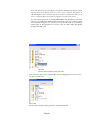
Clicking Password Management in the System Admin menu will activate this screen:
Figure 2-9
Password Management screen activation
Page 14
Adding New User
To add a new user, click the Password Management screen’s ADD button. In the
resulting User Attributes screen (see Figure 2-10 User Attributes screen layout), enter
the user’s name, password and access privileges.
Modifying User
To modify user information, click a user name in the Password Management screen, then
click the MODIFY button. In the resulting User Attributes screen (see Figure 2-10 User
Attributes screen layout), change the user’s name, password, or access privileges.
Deleting User
To delete a user, click a user name in the Password Management screen, then click the
DELETE button.
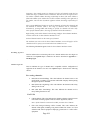
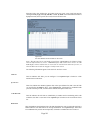
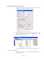
User Attributes screen
The User Attributes screen enables you to add or modify a user’s name, password, and
access privileges.
Figure 2-10
User Attributes screen layout
Clicking the Password Management screen’s ADD or MODIFY button will activate the
User Attributes screen.
Figure 2-11
User Attributes screen activation
The following fields appear in the User Attributes screen:
Page 15
User Name field
This field indicates a person to whom you want to give or subsequently deny access to
the Host. Your required case-sensitive input is limited to 20 alphanumeric characters.
Password field
This field indicates the code validating this user’s access to the Host. Your required
case-sensitive input is limited to 20 alphanumeric characters.
N o t e — Y our
entry appears as a string of asterisks for security.
Confirm Password field
This field indicates for a second time the code validating this user’s access to the
Host in order to assure the first entry was correctly made. Your required case-sensitive
input is the same entry you made in the Password field.
Not e — Your entry appears as a string of asterisks for security. If you fail to enter the
same string as in the Password field, you will receive an error message allowing you to
enter the original password.
System Admin Access field
This field indicates, when checked, that the user has access to the Main Menu/
Toolbar’s System Admin menu. When checked, the letter "A" (without quotes) appears
in the Password Management screen’s User Name field.
Routing Table Access field
This field indicates, when checked, that the user has access to the Main Menu/
Toolbar’s Routing Table menu. When checked, the letter "R" (without quotes)
appears in the Password Management screen’s User Name field.
Maintenance Access field
This field indicates, when checked, that the user has access to the Main Menu/
Toolbar’s Maintenance menu. When checked, the letter "M" (without quotes) appears
in the Password Management screen’s User Name field.
Equipment Access field
This field indicates, when checked, that the user has access to the Main Menu/
Toolbar’s Equipment menu. When checked, the letter "H" (without quotes) appears in
the Password Management screen’s User Name field.
Page 16
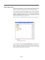
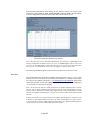
System Setup Screen
The System Setup screen enables you to:
•
Select Call Detail Record (CDR) output options;
•
Setup communication links for the switch, alarm, and redundant ports;
•
Setup LAN connections for Ethernet communications between the Host and
VRU, and the Host and an Dynamis Server; and
•
Configure settings for output of an ACD event log and a remote switch log.
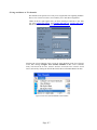
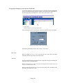
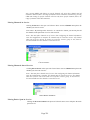
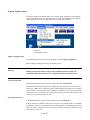
Clicking “System Setup” in the System Admin menu will display the various setup
screens:
Figure 2-12
System Setup screen activation
Saving Changes
Clicking the AP P L Y button activates configuration changes and does not affect calls in
progress. Clicking the OK or SAVE button activates configuration changes and exits
the System Setup screen without effecting calls in progress.
Warning
Changes made to port selections do not take effect until you click the AP P L Y
button or the OK button. Clicking AP P L Y or OK does not affect calls in process.
However, new calls being presented are delayed for several seconds. Caution
should be used when changing communication ports related to the Host link.
The System Setup screen contains areas for CDR Setup, Switch Setup, E2 HOST
Redundant Link, Alarm Logging, and Network.
The following areas and their associated fields appear in the System Setup screen:
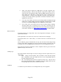
CDR Setup screen
This screen enables you to output Call Detail Record (CDR) files to the Host
Computer’s hard drive, and/or to a TCP/IP port. You can also set the number of days
your system will keep CDR files until automatically deleted from the Host
Computer’s hard drive.
Not e: You can copy CDR files to backup media using the Windows NT/2000 File
Manager.
Page 17
A CDR is a record of all the information pertaining to a particular telephone call (for
example, who made the call, where it went, what time of day it was placed, how long it
took, etc.). The CDR file names reflect the date the files were created (for example,
Ammddyyx.TXT, where x reflects the version number of a particular day’s CDR files).
The Host creates a new file each time the current file reaches a size of 1.37 MB. For
example, the first file created for a particular day would appear as A0530971.TXT.
When that file reaches 1.37 MB (in the same day), a second file is created and would
appear as A0530972.TXT.
The CDRtoday.ICD file contains the current day’s call records and cannot be deleted
because it is the current file being used by the system.
Not e — When disk space on the Host Computer becomes limited, older files should be
copied to other media and deleted from the hard drive. The number of files capable of
being actively stored on the Host’s hard drive depends on the size of the files and the
total amount of available disk space.
Figure 2-13
CDR Setup screen
To add a field, click on the field on the left hand side, then press the Add button. To
remove a field, click on the field on the right hand side, then press the Remove
button. To change the order of the output fields, click on the field on the right hand
side, and click on the Up or Down buttons.
Page 18
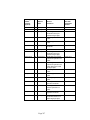
The fields you may select are the following:
•
•
•
•
•
•
•
•
•
•
•
•
•
Answer State (NEW to version 4.7).
o A Call was answered.
o B Operator heard zip tone and hung up before call was connected.
o C A conference bridge call.
o D Caller hung up before a connection was made (call abandoned).
o F Outsize failure reported by outgoing trunk.
o H Hot line transfer.
o O Not answered (Callback).
o P Announcement trunk purge.
o Q Call was in queue but then routed to termination group.
o R Call released from queue before being routed.
o S Operator hung up on caller
o T Transferred call
o W Call was no answer timed out
ANI/CLI Number
DNIS Number
Dial Number
In Span & Channel
Out Span & Channel
Resource Group (Outbound)
Start Time
Billable Time
Sys Duration
Orig Cause Code
Term Cause Code
SS7 NOA
Sample CDR files can be provided by your E2 technical representative.
Write CDR Records to TCP/IP Port field
This field indicates, when checked Yes, that the Host will write CDR files to a
TCP/IP port. Click Yes to write CDR files to a TCP/IP port, or click No if you choose
not to output CDR files to a TCP/IP port.
N o t e — Output to a TCP/IP port requires another computer to login as a Host client
via port 9601. Third -party software is required to read this file and to manipulate its
data.
Write CDR Records to log
This field indicates, when checked Yes, that CDRs will be saved to a file on the Host
Computer’s hard drive. Click Yes to save CDR files on the Host Computer’s hard
drive, or click No if you choose not to save CDR files to the Host Computer’s hard
drive.
CDR Date & Time Format (NEW)
New to version 4.7 – Either the System’s local time can be specified, or GMT.
Logged CDRs maximum age (days)
This field indicates the number of days CDRs will be archived on the Host
computer’s hard drive. The Host archives CDRs on a daily basis, automatically
deleting the oldest files after the specified number of days has been reached. This
Page 19
feature prevents the Host Computer’s hard drive from running out of disk space by
maintaining only the most current records in the system.
Your required input is limited to 0-99 days. The default value is 0. Archived files
remain stored on the hard disk until the number of days has been reached, or you
manually delete the files.
The Host Software does not allow you to delete the CDRtoday.ICD file. This
file is in use and holds the CDRs for the current day’s calls.
Not e —
Page 20
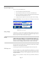
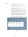
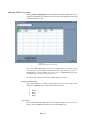
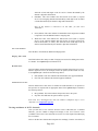
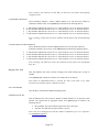
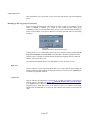
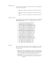
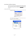
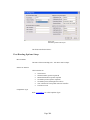
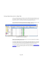
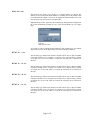
Switch Setup screen
This screen enables you to assign an IP Address to the EXS Switch and configure
ACD event record and call processing activity (debug information) output.
Figure 2-14
Switch Setup screen
ACD Event Log field
This field indicates the output of Automatic Call Distribution (ACD) event records.
Click Online to view call processing activity in real time on a dedicated terminal, or
click Offline to disconnect output of the ACD Event Log.
The Host generates ACD event records as calls progress through your Call Processing
System. The records are identified by type and contain trunk and dialed number
information. These records can be used to provide traffic analysis for fine tuning the
queuing parameters.
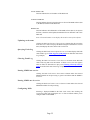
Remote Switch Log field
This field indicates the output of the Remote Switch Log. Click Online to view call
processing (debug) activity in real time on a dedicated terminal or click Offline to
disconnect output of the Remote Switch Log.
The Remote switch log option provides important debugging information such as the
date of the call, how the call was connected, and on which channel the call was
accepted.
Switch IP Address
This field indicates the IP Address of the EXS Switch.
Page 21
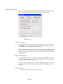
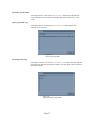
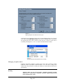
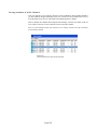
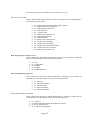
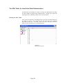
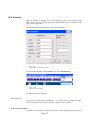
Alarm Setup screen
This screen enables you to write Alarm messages to a TCP/ IP port and Log file on the
Host Computer’s hard drive.
Figure 2-16
Alarm Setup screen
Write Alarms to TCP/IP Port
This field indicates, when checked Yes, that the Host will write alarms to a TCP/IP
port. Click Yes to write alarms to a TCP/IP port, or click No if you choose not to write
alarms to a TCP/IP port.
Logged alarms maximum age
This field indicates the number of days that alarm records will be archived on the
Host computer’s hard drive. The Host archives alarm records on a daily basis,
automatically deleting the oldest files after the specified number of days has been
reached. This feature prevents the Host Computer’s hard drive from running out of
disk space by maintaining only the most current records in the system. The alarm log
file names are files\alarm.dbf and files\alarm.txt
Your required input is limited to 0-90 days. Archived records remain stored on the hard
disk until the number of days has been reached, or you manually delete the records.
Keep Major/Minor/Informational Alarms
By checking these boxes, you may have these types of alarms displayed or ignored.
Page 22
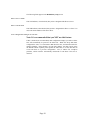
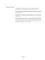
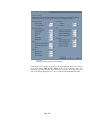
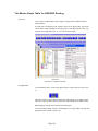
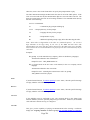
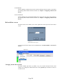
Redundancy setup screen
This screen enables you to select a communications port that allows an active
(running) Host to communicate with a second Host acting as a standby.
Figure 2-17
Redundancy Setup screen
Warning
The running of two different versions of software on the active and standby
Hosts is unprecedented. Dynamis Switching specifically states in product manuals
that the same software must be installed on both Hosts. Dynamis does not
provide any guarantee that a failover from the active to the standby will function
properly. Dynamis Switching will not provide any support if a problem should
arise until both Hosts are running the same version of software and the problem
occurs again. Dynamis Switching only tests redundancy with the same version
on both Hosts.
Not e — Hardware
installation of two Matrix CPU cards is required. (Refer to the
Installation section of the Excel Hardware Manual.) Only one card is active at any
given time, the other is in a standby state. If, for any reason, the first card fails, the
EXS Switch automatically sends a changeover message to the standby. Calls are not
interrupted during the changeover process.
Client and Server, once operational, are always changing. No one machine is
designated as either the Client or the Server. The Client initiates communication
between the Hosts, and the Server is always in a waiting state.
When setting up the system for the first time, select one Host as the Server and the
other Host as the Client.
Page 23
The following fields appear in the Redundancy setup screen:
Host is Server Field
This field indicates, when checked, that you have designated this Host as Server.
Host is Client field
This field indicates, when checked, that you have designated this Host as Client. You
must enter the IP Address of the Server Host.
Pass configuration changes in real time
Note: It is recommended that you NOT use this feature.
If this is checked (not recommended), then configuration changes you make to either
host will automatically be passed to the other host. While this keeps both hosts
configured the same, we recommend to not check this box, and instead transfer the
changes manually. In this manner, one can make changes, test them, and by using
the manual transfer capability either update the other host, or use the other host to
revert both hosts to a previous configuration. Also, it reduces file corruption
problems, which would be automatically transferred to both hosts if this box is
checked.
Page 24
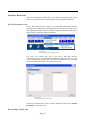
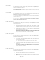
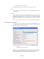
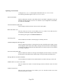
Application Server Link screen
This area of the System Setup screen enables you to select an Applications Protocol
Interface (API) link to an Dynamis Server providing database applications, such as
Smart Calling Card or Smart Long Distance, or to provide integration with other
types of servers. You can also select a communications port between the Host and up
to eight VRUs.
Figure 2-18
Application Server Link screen
Server Data Link list
This list indicates the desired server link for the Data Server. Click one of the following
list items:
•
Offline (default). No Data Server link connection.
•
TCP/IP. For connecting the server over an Ethernet link. The Remote
network name, Network IP address, and Well Known Port fields are
displayed.
•
NETBIOS. For connecting the server via NETBIOS. The Host network
name and Remote network name as defined in the screen.
VRU N Link list
This list indicates the desired VRU link. You can connect up to eight VRUs to the
Host. Click one of the following list items:
•
Offline. No VRU link connection.
•
TCP/IP. For connecting a VRU over an Ethernet link. The Remote
network name, Network IP address, and Well Known Port fields are
displayed.
Page 25
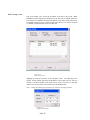
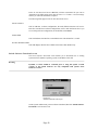
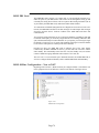
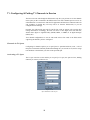
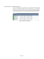
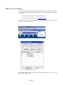
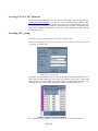
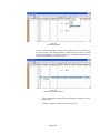
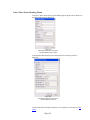
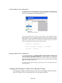
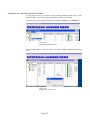
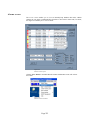
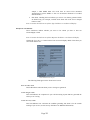
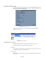
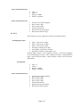
Node Setup screen
This screen enables you to specify the IP address of all nodes in the system. While
Redundancy Setup configures the IP addresses of the first node, if multiple nodes have
been connected via EXNET, then all the IP addresses of the CPUs on the chassis must
be configured using this screen. In the example below, there are two chassis connected
via EXNET, with each chassis having one CPU card.
Figure 2-19
Node Setup screen
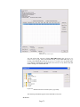
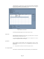
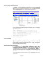
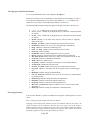
Highlight the node ID and click on the Configure button. The following screen
appears. In this example, this shows the IP address of the single CPU (192.168.10.1)
in node 0, and the IP address of the single CPU in node 1 (192.168.10.3), thus this
reflects a two-switch system, both switches with nonredundant CPUs.
Note: contact your E2 Eagle representative for assistance in setting up nodes.
Figure 2-20
Configure Node screen
Page 26
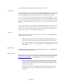
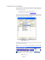
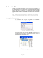
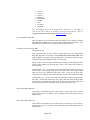
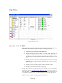
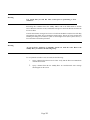
Software Download
Under the Administration Menu, there is the Software Download option, which
allows for E1 PPL download, License Download, and Configuration Download.
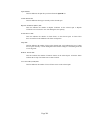
E1 PPL Download screen
The E1 PPL Download screen enables you to download Programmable Protocol
Language (PPL) signaling files to the EXS Switch. Excel Switch creates PPL files to
tailor signaling used with E1 spans to match the variations found when connecting to
different kinds of equipment in different countries.
Figure 2-21
E1 PPL Download screen activation
You must copy custom PPL files to the Host’s hard disk directory
c:\dynamis\ppl_4x.raw. You must then download the files using the E1 PPL Download
screen. The download operation takes a file from the hard disk directory into RAM
for the Host which then loads the file into the EXS Switch.
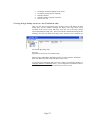
Figure 2-22
E1 PPL Download screen layout
On the System Admin menu, point to Software Download, and then click E1 PPL
Download to activate this screen.
Downloading E1 PPL files
Page 27
In the E1 PPL Download screen’s E2 field, click the custom PPL file you want to
download to the EXS Switch, then click the DOWNLOAD button. A screen message
notifies you when the download is complete.
The following fields appear in the E1 PPL Download screen:
Select Node list
This list indicates, in Exnet configurations, the node (EXS Switch) that will receive
PPL files from the Host. In Exnet configurations, click a node ID from the list. If you
are not using an Exnet configuration, the list defaults to No Exnet.
Switch field
This field indicates the PPL files on the EXS Switch. The default file is CCITT.
E1 PPL Download field
This field displays the PPL files available in the Host’s hard disk directory
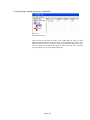
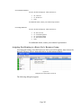
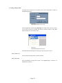
Switch Software Download screen
The Switch Software Download screen enables you to download new or existing
System Software (PSOS's operating system) to the Matrix CPU card.
Warning
Dynamis, or WCS should be contacted prior to using this option. Certain
versions of the Switch Software are only compatible with specific Excel
hardware versions.
Figure 2-23
Software Download screen layout
On the System Admin menu, point to Software Download, then click Switch Software
Download to activate this screen.
Page 28
Figure 2-24
Switch Software Download activation
Downloading Switch Software
In the Switch Software Download screen’s Select Node list, select the node ID of the
EXS Switch that will receive the System Software, then click the SE N D button.
Not e — In
Exnet configurations, click the node ID of the switch that will receive the
System Software. If the configuration is not Exnet, the default node ID is 255.
For CPU versions 1.09 and lower, the download files must be located in the
location excel_4X, with a PSOS4X.BIN.file.
For CPU versions 1.10 and higher, use of BootP and TFT server is required – refer
to your E2 Software representative.
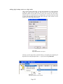
License Download screen
The License Download screen enables you to download the LICENSE.CFG file to the
EXS Switch. The LICENSE.CFG file determines what functionality Excel Switching
provides in your EXS Switch.
When you start the Host to communicate with an Excel Switch that is running Switch
Software version 5.4 or higher, the startup process reads the LICENSE.CFG file in the
Host Computer’s \files subdirectory. This file determines what functionality the EXS
Switch will offer you. If you do not find expected functionality on completion of the
startup process, or if you contract for additional functionality after starting and
configuring Switch Software version 5.4 or higher, you must download the
LICENSE.CFG to the EXS Switch.
Figure 2-25
License Download screen layout
Page 29
On the System Admin menu, point to Software Download then click License
Download to activate this screen.
Figure 2-26
License Download screen activation
Downloading the LICENSE.CFG file
On the System Admin menu, point to Software Download then click License
Download. In the resulting License Download screen, click the YES button to
download the LICENSE.CFG file to the EXS Switch.
Page 30
Backing up System Related Files
You should back up all system related files on a regular basis using the Windows NT
File Manager. These files are stored in the Host computer’s FILES_4X subdirectory.
Sample data, log, system, and E2E files are listed on the following pages:
Data files
Data files are identified by the .DAT filename extension. Data files are updated when
changes are made through the Routing Tables or System Admin functions of the Host.
The data files within the Host are as follows:
CALBACKxx.DAT
If using the Callback application, contains the VRU route list and other Callback
information.
DNIS_xx.DAT
Contains user-definable Digit Table information (where xx is an index number used by
the Trunk Assignment/Digit Tables).
EXCLU_xx.DAT
Contains user-definable Exclusion Table information (where xx is an index number
used by the Trunk Assignment/Digit Tables).
IDS.DAT
Contains the conference IDs to be deleted on startup.
MUSIC.DAT
Contains trunk assignments for Music On Hold.
OUTGRP4X.DAT
Contains user-definable outgoing Resource Group information.
QUEUE1.DAT
Contains user-definable queue list table information.
ROUTELS1.DAT
Contains user-definable route list table information.
STAGE_II.DAT
Contains ANI xlate stage II digit information (maximum of 30 available).
Note: This is an enhancement, as previous versions only allowed 10
TAC4NAME.DAT
If using the TAC application (now marketed as Smart Calling Card), contains
user-definable TAC accounts.
TOD_GRP.DAT
Contains user-definable Time of Day group information.
VRU900.DATC
Contains the VRU route list and branding number information for 900 completion
type.
Page 31
Log files
Log files are identified by the .LOG filename extension. Some log files can become
very large and use up valuable hard disk space. The log files within the Host are as
follows:
ADMIN.LOG
Contains critical error information.
ALARM.LOG
Records switch and VRU alarm events.
CDR.LOG
Records critical events regarding Call Detail Records.
CALLPROC.LOG
Records critical events regarding call processing.
DHI.LOG
Records critical events regarding routing.
EXIT.LOG
Records software exit information.
FUNCT.LOG
Records critical events regarding the Host tasks.
HARDWARE.LOG
Records critical events regarding physical aspects of the EXS Switch.
LAUNCHER.LOG
Records critical events regarding the startup of the Host tasks.
MAINT.LOG
Records critical events regarding logical aspects of the EXS Switch
NETWORK.LOG
Records critical events regarding the Dynamis Server applications and the VRU.
OPERATOR.LOG
Records critical events regarding the user interface.
STARTUP.LOG
Records critical events regarding logical aspects of the EXS Switch on startup.
SWITCH.LOG
Contains normal debug log file information for call processing (must be turned on/ off
from the Maintenance menu).
SWITCH1.LOG
Contains archived debug log file information.
System files
System files are identified by the .SYS filename extension. The system files within the
Host are as follows:
ACCT_4X.SYS
Contains ANI/Account code trunk assignments.
Page 32
E24.SYS
Contains login passwords.
BDHARD5X.SYS
Contains the board status messages and cable ID information.
CCC_CODE.SYS
Contains a list of the country codes.
CIC_CODE.SYS
Contains Carrier Identification Code (CIC) information.
DNIS_TBL.SYS
Contains DNIS files and trunk assignments information.
FILESXFE1.SYS
Contains redundancy files that update the other host.
ISDN_B1.SYS
Contains the ISDN B Channel information.
ISDN_D2.SYS
Contains the ISDN D Channel information.
ISDNbmsg.SYS
Contains information for identically configured ISDN-B Channels.
OPERATOR SYS
Contains supervisor and attendant references.
PORT_5X.SYS
Contains all the trunk information for each span and channel.
PORT_TMR.SYS
Contains the trunk timer information for all span and channels.
TMR_4X.SYS
Contains information used by Startup to configure the timers.
XCLUE. SYS
Contains exclusion files and trunk assignments information.
E2E files
E2 files are identified by the .E2E filename extension. The E2 files within the Host are
as follows:
E21_NT.E2E
Contains task module names for message passing.
E22_NT.E2E
Contains startup messages for all tasks.
E23.E2E
Contains operator menus for the system.
E24_3X.E2E
Contains operator text strings for the system.
E25_NT.E2E
Contains operator text popup menus for the system.
E26_3X.E2E
Contains
Page 33
operator prompts for the system.
CALL_CMP.E2E
Contains call completion types information.
IN_GRP_4X.E2E
Contains incoming start dial information.
Page 34
3. Monitoring Equipment
Introduction
The Host’s chief function is to instruct the EXS Switch to put a call coming into the
switch onto a trunk leaving the switch in a manner that will cause the call to reach its
intended destination.
For the Host to perform this function, you must:
•
know what resources you have in your EXS Switch,
•
put these resources into service with required configurations,
•
assure these resources are in a proper state, and
•
be able to take these resources out of service for reconfiguration
or replacement.
These resources take the form of hot-swappable components (including various cards of
surface-mounted electronic devices) that are inserted into slots of a rack-mountable
chassis. This chassis can be one of two form-factors: the EXS 1000 (formerly, the CSN)
and the higher-capacity EXS 2000 (formerly, the LNX).
Each chassis has a midplane into which processing cards of various kinds are plugged
from a front entry and into which I/O cards for these processing cards are plugged from a
rear entry to form, in some cases, card-pairs. Some of these I/O cards (namely, those
paired with T1 or E1 "line" or "network interface" cards) are points of attachment for
cables from voice networks of local exchange and interexchange carriers and perhaps
also from data networks; other I/O cards are actually HDLC devices to make certain
processing cards (namely, ISDN and SS7 "common channel signaling" cards) redundant.
One of these processing cards (namely, the EXNET Controller card) is a point of
attachment for EXNET cables from other chassis that make up a multi-node EXS Switch.
You manage most of these resources or components in screens accessed from the
Equipment List screen.
Equipment List
The Equipment List screen enables you to determine the distribution of components in your
single-node or multinode EXS Switch, as well as to access screens that display the current
status of these components and give you a means to put and take these components into
and out of service, if not configure them.
Card-related icons
The Equipment List screen uses various icons to represent equipment that may be installed
in your EXS Switch:
Page 35
icon. This icon represents various models of the digital signal processing card (see DSP Card for details on the
functionality, monitorability and configurability of this kind of card). Associated with this icon is the node (if a
multinode EXS Switch) and slot number where the specified card resides.
icon. This icon represents various models of the E1 card (see E1 Card for details on the functionality,
monitorability and configurability of this kind of card). Associated with this icon is the node (if a multinode EXS
Switch) and slot number where the specified card resides, together with this card’ parenthetically listed span IDs.
icon. This icon represents the EX/CPU card (see EX/CPU Card for details on the functionality, monitorability
and configurability of this kind of card). Associated with this icon is the node (if a multinode EXS Switch) and slot
number where the specified card resides.
icon. This icon represents the EXNET Controller card (see EXNET Controller card for details on the
functionality of this kind of card). Associated with this icon is the node and slot number where the specified
card resides, together with the ID of the ring of which it is a part, the number of packets it transfers per timeslot and
an indication of whether the card both transmits ("X") and receives ("R") or just receives.
icon. This icon represents various models of the fan tray (see Fan Tray for details on the functionality,
monitorability and configurability of this fan tray). Associated with this icon is the node (if a multinode EXS
Switch) and slot number where the specified fan tray resides.
icons. The first icon represents the ISDN PRI card (see ISDN PRI Card for details), with the card in
service. The second indicates the card is out of service. New to 2007, out of service cards may be configured.
Associated with this icon is the node (if a multinode EXS Switch) and slot number where the specified card resides.
icon. This icon represents the chassis (or node, in a multinode EXS Switch) and/or the chassis’s (or node’s)
midplane (see Midplane for details on the functionality of this kind of card). Associated with this icon is the node (if
a multinode EXS Switch) and logical slot number of the midplane, together with the chassis serial #.
icon. This icon represents the power supply card (see Power Supply Card for details on the functionality,
monitorability and configurability of this kind of card). Associated with this icon is the node (if a multinode
EXS Switch) and slot number where the specified card resides.
icon. This icon represents the SS7 card (see SS7 Card for details on the functionality, monitorability and
configurability of this kind of card). Associated with this icon is the node (if a multinode EXS Switch) and slot
number where the specified card resides.
icon. This icon represents various models of the T1 card (see T1 Card for details on the functionality,
monitorability and configurability of this kind of Card). Associated with this icon is the node (if a multinode EXS
Switch) and slot number where the specified card resides, together with this card’ parenthetically listed span IDs.
Two other icons indicate you have a serious problem with a card or a disparity between the configuration file in
your Host and the actual configuration in your EXS Switch.
icon. This icon indicates a non-functioning card. This card could not initialize and report itself to the
EX/CPU card and therefore the Host. To regain this card’s functionality, you must replace it.
Page 36
icon. This "X" icon indicates that a card recorded in your Host’s configuration file, but the card is not present
in your EXS Switch. This typically occurs when a person has removed a card without first stopping the software.
Host’s configuration file (and “X” icon)
Not only does the Host’s configuration file record the actual distribution of
components in the EXS Switch, this file also holds data of configurations you have
made for each of these distributed components.
Should you need to pull a card from the EXS Switch, then reinsert it (or replace it with
the same model) in the same location, the Host will automatically download that card’s
configuration data to the EXS Switch to effect configuration of that card (which will
have lost its configuration on being pulled).
N o t e — Once a card is reinserted/replaced and configured, the "X" icon, which
displays after pulling this card, will be replaced with the icon that represents the kind of
card now present.
Should you put a different model of a card in the exact place of the same kind of card,
the Host will automatically download the configuration data to the EXS Switch to
effect configuration of that kind of card (which will not have a configuration).
N o t e — Once
a different model is inserted and configured, the "X" icon, which displays
after pulling the other model, will be replaced with the icon that represents the kind of
card now present.
In the case of a T1/E1 card, automatic configuration will occur on available spans.
For example, if a 16-span model replaces an eight-span model, the configuration of
the eight-span model will be retained in the first eight spans of the 16-span model; if
an eight-span model replaces a 16-span model, the configuration of the 16-span
model’s first eight spans will be retained in the eight-span model and the
configuration of the remaining eight spans will be removed from the configuration file.
In the case of an SS7 card, automatic configuration will occur on available links. For
example, if a 16-link model replaces an four-link model, the configuration of the fourlink model will be retained in the first four links of the 16-link model; if an fourlink
model replaces a 16-link model, the configuration of the 16-link model’s first four
links will be retained in the four-link model and the configuration of the remaining 12
links will be kept the configuration file until you remove them.
Page 37
Should you replace a card with a different kind, the Host will automatically delete
configuration data for the removed card from the configuration file and stand ready to
accept configuration data you will create.
Not e — Once
a new card is inserted, the Host will display an icon representing the kind
of card now present. If the card is configurable, you must configure it.
Should you want to pull a card from the switch and not replace it, you need only pull the
card, then select the card in the Equipment List screen, now represented by an "X"
icon, and press the DE L E T E key to remove its configuration data from the configuration
file.
Viewing Equipment by Type
In View by Type mode, the Equipment List screen’s View by Type field enables you to
view components of the same kind regardless of their physical location. For example,
the Equipment List screen will group EX/CPU cards in physical chassis or node 0 (0-33)
and node 1 (1-32).
Figure 3-1
Equipment List screen layout (View by Type mode)
Clicking List by Type in the Main Menu/Tool Bar’s Equipment menu will activate
this screen and mode.
Figure 3-2
Equipment List screen activation (for View by Type mode)
Not e — If
you are already in the Equipment List screen in another mode, you can
Page 38
also click the View by Type button to change the Equipment List screen to View by
Type mode.
Viewing Equipment by Slot ID
In View by Slot ID mode, the Equipment List screen enables you to view equipment
by the Slot ID, regardless of node, if in a multinode EXS Switch, or type, in
numerical sequence.
Figure 3-3
Equipment List screen layout (View by Slot ID mode)
Clicking List by Slot ID in the Main Menu/Tool Bar’s Equipment menu will
activate this screen and mode.
Figure 3-4
Equipment List screen activation (for View by Slot ID mode)
Not e — If
you are already in the Equipment List screen in another mode, you can also
click the View by Slot ID button to change the Equipment List screen to View by
Page 39
Slot ID mode.
Viewing Equipment by Node
In View by Node mode, the Equipment List screen enables you to view equipment by
node in a fiberoptic ring configuration called EXNET.
Figure 3-5
Equipment List screen layout (View by Node mode)
Clicking List by Node in the Main Menu/Tool Bar’s Equipment menu will activate this
screen and mode.
Page 40
Figure 3-6
Equipment List screen activation (for View by Node mode)
Not e — If you are already in the Equipment List screen in another mode, you can also
click the View by Node button to change the Equipment List screen to View by Node
mode.
This mode is available only if you have configured an EXNET ring.
Page 41
Power Supply Card
The power supply card’s purpose is to take in -48V DC from an external power source
and put out 5V DC from each of its power modules (the EXS 1000 chassis’ power
supply has one module; the EXS 2000 chassis’ power supply has three modules).
You cannot make power supply cards redundant. However, you can put an additional
power supply card in the same node of your EXS Switch and wire it to the same or, more
securely, to a different - 48V DC power source (see Excel Switching’s Hardware
installation and Maintenance Guide for details). The second power supply card’s
voltage will be pooled with the first. Should one power supply card fail, the EXS
chassis can still have sufficient power from the other.
The Power Supply Card screen enables you to view the status of a power supply card.
Figure 3-7
Power Supply Card screen layout
You can activate this screen by clicking Power Supply Card in the Equipment List
screen’s View by Type mode, then double-clicking a listed power supply card; or by
clicking a listed power supply card in the Equipment List screen’s View by Slot ID
mode; or by clicking a selected node in the Equipment List screen’s View by Node
mode, then double-clicking a listed power supply card.
Page 42
Figure 3-8
Power Supply Card screen activation (View by Type mode)
The following information appears in the Power Supply Card screen:
Model line
This line indicates the model of this power supply card.
Node/Slot line
This line indicates the node in the EXS Switch and slot (in the node’s chassis) where this
power supply card resides.
Not e — In
a single-node EXS Switch, "Node" does not display; in a multinode EXS
Switch, "Node" will display together with an automatically-generated number
identifying the node.
A chassis’ power supply card is associated with slot 17 and/or 18.
Last Card Status line
This line indicates (in MM-DD-YY HH:MM:SS format) when this power supply card’s
status was last updated.
Hardware Status line
This line indicates whether this power supply card is in service. One of the following
messages will occur:
•
On Line. This card is providing power to the chassis.
•
Off Line. This card is not providing power to the chassis. If you want to regain
backup power, you must swap this card and call Dynamis’ Customer Engineering
immediately.
Module n line
This line indicates whether the numbered power supply module is supplying power to
the chassis within tolerance. One of the following messages will occur:
•
OK. This module is providing power to the chassis that is within tolerance.
•
FAILED. This module is providing power to the chassis that is out of tolerance.
Page 43
Not e — If
this power supply card serves an EXS 1000 chassis, disregard the
status of modules 2-3.
Warning
Not replacing a power supply card that has modules out of tolerance can damage
call processing cards and cause their operation to cease. Excel Switching strongly
advises you to replace a power supply card with one or more defective modules
immediately.
Updating card status
Clicking the Power Supply Card screen’s UP D A T E ST A T U S button after this screen has
been active for a while will query this power supply card again to determine its current
status, then display this status in the Power Supply Card screen.
Page 44
Midplane
The chassis midplane’s purpose is to provide various data and other buses
that can:
•
distribute power from the power supply to all cards in the chassis
•
join I/O cards with the processing cards in the chassis that control them
•
join redundant processing cards
•
make I/O cards available to other nodes on an EXNET ring
The Midplane screen enables you to view the status of the midplane.
Figure 3-9
Midplane screen layout
You can activate this screen by clicking Midplane in the Equipment List
screen’s View by Type mode, then double-clicking a listed midplane; or by
clicking a listed midplane in the Equipment List screen’s View by Slot ID
mode; or by clicking a selected node in the Equipment List screen’s View by
Node mode, then doubleclicking a listed midplane.
Figure 3-10
Midplane screen activation (View by Type mode)
Page 45
The following information appears in the Midplane screen:
Model line
This line indicates the model of this midplane.
Node/Slot line
This line indicates the node in the EXS Switch and slot (in the node’s chassis)
where this midplane resides.
Not e — In a single-node EXS Switch, "Node" does not display; in a multinode
EXS Switch, "Node" will display together with an automatically-generated
number identifying the node.
A chassis’ midplane is associated with logical slot 19.
Last Card Status line
This line indicates (in MM-DD-YY HH:MM:SS format) when this midplane’s
status was last updated.
Chassis Serial line
This line indicates the serial number of the midplane.
Updating midplane status
Clicking the Midplane screen’s UP D A T E ST A T U S button after this screen has
active for a while will query this midplane again to determine its
been
current status, then display this status in the Midplane screen.
Page 46
Fan Tray
The fan tray’s purpose is to mount multiple fans in your EXS Switch chassis.
These fans force the chassis’ warm air into its environs and draw the
environ’s relatively cooler air into the chassis to maintain the chassis’s
required operating temperature.
The Fan Tray screen enables you to view the status of a fan tray’s multiple
fans.
Figure 3-11
Fan Tray screen layout
You can activate this screen by clicking Fan Tray in the Equipment List
screen’s View by Type mode, then double-clicking a listed fan tray; or by
clicking a listed fan tray in the Equipment List screen’s View by Slot ID
mode; or by clicking a selected node in the Equipment List screen’s View by
Node mode, then double clicking a listed fan tray.
Figure 3-12
Fan Tray screen activation (View by Type mode)
The following information appears in the DSP Card screen:
Model line
This line indicates the model of this fan tray. Current models include:
Page 47
•
Fan Tray. This tray mounts six fans in the EXS 1000 chassis.
•
Front Fan Tray. This tray mounts four fans in the EXS 2000 chassis’s
underside (accessed from the chassis’ front).
Rear Fan Tray. This tray mounts three fans in the EXS 2000
chassis’s topside (accessed from the chassis’ rear).
•
Node/Slot line
This line indicates the node in the EXS Switch and slot (in the node’s chassis)
where this fan tray resides.
Not e — In a single-node EXS Switch, "Node" does not display; in a multinode
EXS Switch, "Node" will display together with an automatically-generated
number identifying the node.
An EX 1000 chassis’ fan tray is associated with logical slot 16; an EX 2000
chassis’ front fan tray is associated with logical slot 10 and its rear fan tray
is associated with logical slot 22.
Last Card Status line
This line indicates (in MM-DD-YY HH:MM:SS format) when this fan tray’s
status was last updated.
Fan Tray Status line
This line indicates whether the numbered fan in its tray is in service. One of
the following messages might occur:
•
OK. This numbered fan is in service.
•
FAILED. This numbered fan is not in service.
Not e — If
this fan tray is an EX 2000 chassis’ front fan tray, disregard the
status of fans 5-6; if this fan tray is an EX 2000 chassis’ rear fan tray,
disregard the status of fans 4-6.
Failure of a single fan will not usually endanger call processing or the
cards performing this activity.
Warning
Not replacing failed fans will cause heat to build up inside the chassis;
this buildup of heat will eventually damage call processing cards and cause
their operation to cease. Excel Switching strongly advises you to replace
failed fans immediately.
Updating fan tray status
Clicking the Fan Tray screen’s UP D A T E ST A T U S button after this screen has
been active for a while will query this fan tray again to determine its current
status then display this status in the Fan Tray screen.
Page 48
DSP Card
The DSP card’s purpose is to generate and receive tones (DTMF, MFR1,
MFR2 CPA, CPG and bong) that can:
• represent address digits for routing a call within its channel,
• indicate the call’s progress (for example, with dial tone or ringback),
and/or
• prompt the caller for an action.
Another purpose of the DSP card is to provide a bridge for conferences of
callers who can both speak and listen, and/or just listen.
To provide a node in your EXS Switch with particular tone or conferencing
capabilities, you must select and assign these capabilities one for each of four
digital signal processors on up to four SIMMs (single inline memory
modules) per DSP card (16 DSPs maximum).
You cannot make DSP cards redundant. However, you can put an additional
DSP card in the same node of your EXS Switch and its DSP resources will be
pooled with the other. Should one DSP card fail, you can still have necessary
support if the other DSP card’s DSPs have been configured like the lost
DSPs.
The DSP Card screen enables you to view the status of a DSP card, as well as
to assign tone and conferencing capabilities to DSPs of the card.
Figure 3-13
DSP Card screen layout
Page 49
Note — The DSP Card screen shows a green icon in the leftmost column when
an adjacent SIMM is in service. A red icon displays when a SIMM is not in
service.
You can activate this screen by clicking DSP Card in the Equipment List
screen’s View by Type mode, then double-clicking a listed DSP card, or by
clicking a listed DSP card in the Equipment List screen’s View by Slot ID
mode, or by clicking a selected node in the Equipment List screen’s View by
Node mode, then double clicking a listed DSP card.
Figure 3-14
DSP Card screen activation (View by Type mode)
The following information appears in the DSP Card screen:
Model line
This line indicates the model of this DSP card. Current models include:
•
•
DSP-ONE
MFDSP
Node/Slot line
This line indicates the node in the EXS Switch and slot (in the node’s chassis)
where this DSP card resides.
Not e — In a single-node EXS Switch, "Node" does not display; in a multinode
EXS Switch, "Node" will display together with an automatically-generated
number identifying the node.
Last Card Status line
This line indicates (in MM-DD-YY HH:MM:SS format) when this DSP card’s
status was last updated.
Page 50
Card Status line
This line indicates whether this DSP card is in service, has suffered faults, has
good memory and/or has good configuration data, as well as how it was last
reset. One or more of the following messages might occur:
•
Reset by insertion. An insertion of this DSP card in the chassis
caused this card’s last reset.
•
Reset by software. A taking of this DSP card out of service then
putting it back in service from the Host, or a powering down then up
of the entire chassis, or a fault in this card caused this card’s last
reset.
•
Reset by button. A push of this DSP card’s RESET button caused
this card’s last reset.
•
OUT OF SERVICE BY SWITCH. An EX/CPU card has reported
this DSP card to be out of service. If this card’s dipswitch 3 is set to
ON, if another DSP card does not have this same message, and if
resetting this card does not remove this message, you must swap this
card and call Dynamis’ Customer Engineering immediately.
•
In service. This DSP card is in service.
•
CONFIG DATA INVALID. The configuration data for this DSP
card has been lost and has not been downloaded from the Host.
•
FAULTS LOGGED. One or more faults have occurred in this DSP
card. You must retrieve this card’s Fault Log (see Querying Fault
Log, below), then report its contents to Dynamis’ Customer
Engineering immediately.
•
MEMORY TEST FAILED. This DSP card has failed a self-test of
its memory. You must determine whether the card has a ROM or
RAM problem (see Memory Test line, below).
•
CARD FAILURE. This DSP card failed for an unspecified reason.
If resetting this card does not remove this message, you must call
Dynamis’ Customer Engineering immediately.
Memory Test line
This line indicates the result of a self-test at the last status update of the
integrity of ROM and RAM devices on this DSP card. The following
messages can occur:
•
OK. Test proved memory was reliable.
•
ROM CHECKSUM FAILED. Test proved read-only memory was
unreliable. You must swap the card and call Dynamis’ Customer
Engineering immediately.
•
RAM TEST FAILED. Test proved random access memory was
unreliable. If resetting this card does not remove this message, you
must call Dynamis’ Customer Engineering immediately.
Artwork Revision line
This line indicates the revision level of this DSP card’s circuit design.
Page 51
Serial Number line
This line indicates the serial number of this DSP card.
Software ROM line
This line indicates the major, then the minor revision of the ROM software (that
is, the BIOS) installed on this DSP card.
Build # line
This line indicates the build number of the RAM software (that is, the System
Software, sometimes called pSOS) downloaded from an EX/CPU card to this
DSP card.
N o t e — The
Switch Status screen displays the actual version of this software.
Updating card status
Clicking the DSP Card screen’s UPDATE STATUS button after this screen has
been active for a while will query this DSP card again to determine its current
status, then display this status in the DSP Card screen.
Querying Fault Log
Clicking the DSP Card screen’s QUERY FAULT LOG button displays this DSP
card’s Fault Log (see Fault Log query [with fault] for an EX/CPU card’s Fault
Log example).
Clearing Fault Log
Clicking the DSP Card screen’s CLEAR FAULT LOG button clears this DSP
card’s Fault Log and resets the number of faults to zero (zero also appears
when no faults are detected on a query) (see Fault Log cleared [or clear] of
faults for an EX/CPU card’s Fault Log example).
Putting SIMM into service
Clicking the DSP Card screen’s INTO SERVICE button makes the selected
SIMM available for call processing. A green icon indicates that the SIMM is
in service.
Putting SIMM out of service
Clicking the DSP Card screen’s OUT OF SERVICE button makes the selected
SIMM unavailable for call processing.
Configuring DSPs
Selecting a displayed SIMM in the DSP Card screen, then clicking the
CONFIGURE button after clicking the OUT OF SERVICE button enables you to
configure DSPs on that SIMM.
Page 52
Figure 3-15 DSP
SIMM Configure screen layout
The following information appears in the DSP SIMM Configure screen:
DSPn lists
These lists indicate how a selected digital signal processor handles bong, CPA,
CPG, DTMF, MFR1 and MFR2 tone signaling, or how it handles conferences
of callers who can both speak and listen as well as callers who can only listen.
Your required input is limited to the following choices:
•
Bong A. DSP can simultaneously generate a bong tone prompt subject to
A-law on up to 16 channels (if DSP-ONE model) or six channels (if
MFDSP model) per node of your EXS Switch.
•
Bong u. DSP can simultaneously generate a bong tone prompt subject to
µ-law on up to 16 channels (if DSP-ONE model) or six channels (if
MFDSP model) per node of your EXS Switch.
•
Conf Mixed. DSP can support up to 34 simultaneous Conferences
bridging four/seven speakers/listeners (if DSP-ONE model) or only one
Conference bridging four/seven speakers/listeners (if MFDSP model)
subject in part to A-law and in part to µ-law.
•
Conxfer u. DSP can support up to 14 simultaneous Conferences bridging
four/ seven speakers/listeners and a channel-limited number of listeners
(if DSP-ONE model) or only one Conference bridging four/seven
speakers/ listeners and a channel-restricted number of listeners (if
MFDSP model) subject to
µ-law.
•
Conxfer A. DSP can support up to 14 simultaneous Conferences
bridging four/seven speakers/listeners and a channel-limited number of
listeners (if DSP-ONE model) or only one Conference bridging
four/seven speakers/ listeners and a channel-restricted number of
listeners (if MFDSP model) subject to A-law.
•
CPA A. DSP can simultaneously receive Call Progress Analysis signals
subject to A-law on up to 20 channels (if DSP-ONE model) or 13
channels (if MFDSP model) per node of your EXS Switch.
•
CPA u (default for DSP 3 on SIMM 1). DSP can simultaneously receive
Call Progress Analysis signals subject to µ-law on up to 20 channels (if
DSP-ONE model) or 10 channels (if MFDSP model) per node of your
EXS Switch.
•
CPG A. DSP can simultaneously generate Call Progress Tone Group
signals subject to A-law on all channels per node of your EXS Switch.
Page 53
•
CPG u (default for DSP 2 on SIMM 1). DSP can simultaneously
generate Call Progress Tone Group signals subject to µ-law on all
channels per node of your EXS Switch.
•
DTMF GA. DSP can simultaneously generate DTMF signals subject to
A-law on all channels per node of your EXS Switch.
•
DTMF Gu (default for DSPs 0 and 1 on SIMM 1). DSP can
simultaneously generate DTMF signals subject to µ-law on all channels
per node of your EXS Switch.
•
DTMF RA. DSP can simultaneously receive DTMF signals subject to Alaw on up to 22 channels (if DSP-ONE model) or 13 channels (if
MFDSP model) per node of your EXS Switch.
•
DTMF Ru (default for DSPs 0, 1, 2 and 3 on SIMM 0 and DSPs 0, 1, 2
and 3 on SIMM 3). DSP can simultaneously receive DTMF signals
subject to µ-law on up to 22 channels (if DSP-ONE model) or 13
channels (if MFDSP model) per node of your EXS Switch.
•
Energy Detect – Review your Escel Switching Hardware Manual or
contact your E2 technical representative if you wish to use this feature
•
MFR1 GA. DSP can simultaneously generate MFR1 signals subject to
A-law on all channels per node of your EXS Switch.
•
MFR1 Gu. DSP can simultaneously generate MFR1 signals subject to µlaw on all channels per node of your EXS Switch.
•
MFR1 RA. DSP can simultaneously receive MFR1 signals subject to Alaw on up to 45 channels (if DSP-ONE model) or 13 channels (if MFDSP
model) per node of your EXS Switch.
•
MFR1 Ru (default for DSPs 0, 1, 2 and 3 on SIMM 2). DSP can
simultaneously receive MFR1 signals subject to µ-law on up to 45
channels (if DSP-ONE model) or 13 channels (if MFDSP model) per
node of your EXS Switch.
•
MFR2 GAB. DSP can generate MFR2 signals subject to A-law in
response to signals received by its node of your EXS Switch.
•
MFR2 GAF. DSP can simultaneously generate MFR2 signals subject to
A-law on all channels per node of your EXS Switch.
•
MFR2 GuB. DSP can generate MFR2 signals subject to µ-law in
response to signals received by its node of your EXS Switch.
•
MFR2 GuF. DSP can simultaneously generate MFR2 signals subject to
µ-law on all channels per node of your EXS Switch.
•
MFR2 RA. DSP can simultaneously receive MFR2 signals subject to Alaw on up to 30 channels (if DSP-ONE model) or 13 channels (if MFDSP
model) per node of your EXS Switch.
•
MFR2 Ru. DSP can simultaneously receive MFR2 signals subject to µlaw on up to 30 channels (if DSP-ONE model) or 13 channels (if MFDSP
model) per node of your EXS Switch.
•
Monitor All. DSP supports up to 34 simultaneous Conferences bridging
four/ seven speakers/listeners and a channel-limited number of listeners
(if DSPONE model) or only one Conference bridging four/seven
speakers/listeners and a channel-limited number of listeners (if MFDSP
model) subject in part to A-law and in part to µ-law.
Page 54
N o t e — Receivers
handle only a limited number of channels; you must add
receivers in a quantity that will match the total number of incoming channels
of your EXS chassis or your switch will drop calls for want of a receiver.
Generators of each kind handle all channels of your EXS chassis; you need
not add more than one kind of receiver unless you require redundancy of that
kind; for redundancy, you should put the second generator of a given kind on
another DSP card in the same chassis, or at least on a different SIMM of the
same card.
MFR2 RA, MFR2 GAB and MFR2 GAF must be on same DSP card, if on
different SIMMs. MFR2 Ru, MFR2 GuB and MFR2 GuF must be on same
DSP card, if on different SIMMs.
Page 55
T1 Card
The T1 card’s purpose is to convey up to 24 sampled and quantized voice calls (and
perhaps call control data) over each T1 span of your EXS Switch to and from voice
networks (and perhaps data networks) within North America.
To be conveyed over an T1 span, voice calls must first be setup for connection and
finally torn down once completed. The setting up and tearing down of a voice call can
occur through an exchange within that call’s channel of the tones and bit indications
that make up MFR1 "channel-associated" signaling (a DSP card must be present in T1
card’s chassis for this kind of signaling; see DSP Card).
Alternatively, the setting up and tearing down of a voice call can occur through an
exchange not in the call’s channel but in a separate channel of the data messages that
make up either ISDN or SS7 "common channel" signaling (an ISDN or SS7 card must be
present in T1 card’s chassis for this kind of signaling; see ISDN PRI Card or SS7
Card). A given ISDN or SS7 data channel carries setup/teardown messages that can
control many voice channels at one time; SS7 channels, or links, occur in T1 spans
connected to an SS7 data network rather than to the voice network.
T1 cards can be paired with either a standard I/O card, a redundant I/O card, or a
standby I/O card. Provided you have another T1 card in the same chassis paired with a
standby I/O card, any T1 card you have paired with a redundant I/O card can fail and
its calls will handled by the T1 card paired with the standby I/O card. In this "N+1"
redundancy, only one T1 card can fail per chassis. T1 cards paired with standard I/O
cards cannot be made redundant.
The T1 Card screen enables you to view the status of a T1 card, as well as to bring its
T1 spans in and out of service and to give "N+1" redundancy to the T1 card.
Page 56
Figure 3-16
T1 Card screen layout
N o t e — The T1 Card screen shows no icon in the leftmost column when the status of an
adjacent offset on a card in service cannot be determined. An "X" icon displays when
an offset has been in service but its card has been taken out of service, or when the Host
has not been able to configure an assigned offset for some reason. An "!" icon displays
when an offset’s configuration is retained on the card but does not correspond to
configuration data in the Host.
You can activate this screen by clicking T1 Card in the Equipment List screen’s View
by Type mode, then double-clicking a listed T1 card, or by clicking a listed T1 card in the
Equipment List screen’s View by Slot ID mode, or by clicking a selected node in the
Equipment List screen’s View by Node mode, then double-clicking a listed T1 card.
Page 57
Figure 3-17
T1 Card screen activation
N o t e — The
above figure shows redundant T1 cards. The highlighted card is active
("A"); one of the other T1 cards is standby ("S"); remaining T1 cards are paired with
standard I/O cards and cannot be redundant.
The following information appears in the T1 Card screen:
Model line
This line indicates the model of this T1 card. Current models include:
•
4-Span ST1LC. This model supports 96 digital voice channels at 64 Kbps each.
•
8-Span ST1LC. This model supports 192 digital voice channels at 64 Kbps each.
•
T-ONE 8-Span. This model supports 192 digital voice channels at 64 Kbps each.
•
T-ONE 16-Span. This model supports 384 digital voice channels at 64 Kbps
each.
Node/Slot line
This line indicates the node in the EXS Switch and slot (in the node’s chassis) where this
T1 card resides.
Not e — In
a single-node EXS Switch, "Node" does not display; in a multinode EXS
Switch, "Node" will display together with an automatically-generated number
identifying the node.
Last Card Status line
This line indicates (in MM-DD-YY HH:MM:SS format) when this T1 card’s status was
last updated.
Page 58
Card Status line
This line indicates whether this T1 card is in service, has suffered faults, has good
memory and/or has good configuration data, as well as how it was last reset. One or
more of the following messages might occur:
•
Reset by insertion. An insertion of this T1 card in the chassis caused this
card’s last reset.
•
Reset by software. A taking of this T1 card out of service then putting it back in
service from the Host, or a powering down then up of the entire chassis, or a fault
in this card caused this card’s last reset.
•
Reset by button. A push of this T1 card’s RESET button caused this card’s
last reset.
•
Standby I/O present. This T1 card is associated with an "N+1" standby I/O card
rather than a redundant I/O card and will handle traffic of a redundant I/O card
associated with a failed T1 card if Redundancy Status (see below) is "Standby".
N o t e — If Redundancy Status is "Non-redundant", you can click the OU T OF
SERVICE button, then click the IN SERVICE button to change Redundancy Status to
"Standby ".
•
OUT OF SERVICE BY HOST. Someone has taken this T1 card out of service
through the Host.
•
OUT OF SERVICE BY SWITCH. An EX/CPU card has reported this T1 card
to be out of service. If this card’s dipswitch 3 is set to ON, if another T1 card
does not have this same message, and if resetting this card does not remove this
message, you must swap this card and call Dynamis’ Customer Engineering
immediately.
•
In service. This T1 card is in service.
•
CONFIG DATA INVALID. The configuration data for this T1 card has been
lost and has not been downloaded from the Host.
•
FAULTS LOGGED. One or more faults have occurred in this T1 card. You
must retrieve this card’s Fault Log (see Querying Fault Log, below), then
report its contents to Dynamis’ Customer Engineering immediately.
•
MEMORY TEST FAILED. This T1 card has failed a self-test of its memory.
You must determine whether the card has a ROM or RAM problem (see
Memory Test line, below).
•
CARD FAILURE. This T1 card failed for an unspecified reason. If resetting
this card does not remove this message, you must call Dynamis’ Customer
Engineering immediately.
Page 59
Redundancy Status line
This line indicates whether this T1 card was in a redundant mode (that is, matched
with another card of the same kind in the same chassis, and either communicating with
it or ready to communicate with it) and, if so, what relationship it had with the other
card at the last status update. One of the following messages will occur:
•
Non-redundant. This T1 card is not in redundant mode.
•
Active. This T1 card is in redundant mode and is the card in control.
Not e — The
letter "A" appears next to this card’s icon in the Equipment List
screen to indicate an active state.
•
Standby. This T1 card is in redundant mode and is ready to take control if the
active T1 card fails.
Not e — The
letter "S" appears next to this card’s icon in the Equipment List
screen to indicate a standby state.
•
Serving. This T1 card is in redundant mode and is providing service to a
redundant I/O card whose associated T1 card has failed.
Not e — The
letter "S" appears next to this card’s icon in the Equipment List
screen to indicate a serving state.
If this T1 card is in a serving state, no other card in the chassis can be in this
state; if another card is in this state, this T1 card cannot be in a serving state.
•
Synchronizing. This T1 card is in redundant mode and is exchanging
configuration data with the other T1 card.
N o t e — If synchronization fails, this card will become non-redundant. An
asterisk (*) appears next to this card’s icon in the Equipment List screen to
indicate a synchronizing state.
•
FAIL. This T1 card has failed for an unspecified reason. If resetting this card
does not remove this message, you must call Dynamis’ Customer
Engineering immediately.
Not e — The
letter "F" appears next to this card’s icon in the Equipment List
screen to indicate a failed state.
Memory Test line
This line indicates the result of a self-test at the last status update of the integrity of
ROM and RAM devices on this T1 card. The following messages can occur:
•
OK. Test proved memory was reliable.
•
ROM CHECKSUM FAILED. Test proved read-only memory was
unreliable. You must swap the card and call Dynamis’ Customer Engineering
immediately.
•
RAM TEST FAILED. Test proved random access memory was unreliable. If
resetting this card does not remove this message, you must call Dynamis’
Customer Engineering immediately.
Page 60
Artwork Revision line
This line indicates the revision level of this T1 card’s circuit design.
Serial Number line
This line indicates the serial number of this T1 card.
Software ROM line
This line indicates the major, then the minor revision of the ROM software (that is, the
BIOS) installed on this T1 card.
Build # line
This line indicates the build number of the RAM software (that is, the System
Software, sometimes called pSOS) downloaded from an EX/CPU card to this T1 card.
N o t e — The
Switch Status screen displays the actual version of this software.
Updating card status
Clicking the T1 Card screen’s UPDATE STATUS button after this screen has been
active for a while will query this T1 card again to determine its current status, then
display this status in the T1 Card screen.
Querying Fault Log
Clicking the T1 Card screen’s QUERY FAULT LOG button displays this T1 card’s Fault
Log (see Fault Log query [with fault] for an EX/CPU card’s Fault Log example).
Clearing Fault Log
Clicking the T1Card screen’s CLEAR FAULT LOG button clears this T1 card’s Fault
Log and resets the number of faults to zero (zero also appears when no faults are
detected on a query) (see Fault Log cleared [or clear] of faults for an EX/ CPU card’s
Fault Log example).
Putting T1 card in service
Clicking the T1 Card screen’s IN SERVICE button makes this T1 card available for
call processing.
Not e — If you are putting the T1card in service after having configured it and taken it out
of service, the Host will download the T1 configuration data the card lost when you
took it out of service.
Putting T1 card out of service
Clicking the T1 Card screen’s OUT OF SERVICE button makes this T1 card unavailable
for call processing.
Not e — You
will want to take this card out of service if you need to test the card or if you
discover the card is faulty. Taking this card out of service automatically clears all T1
configuration data and also takes voice channels out of service.
Page 61
Returning T1 card to active status
Clicking the T1 Card screen’s Active checkbox returns this once-failed T1 card back
to active status.
Page 62
E1 Card
The E1 card’s purpose is to convey up to 30 sampled and quantized voice calls (and
perhaps call control data) over each E1 span of your EXS Switch to and from voice
networks (and perhaps data networks) outside North America and Japan.
To be conveyed over an E1 span, voice calls must first be setup for connection and
finally torn down once completed. The setting up and tearing down of a voice call can
occur through an exchange within that call’s channel of the tones and bit indications
that make up MFR2 "channel-associated" signaling (a DSP card must be present in E1
card’s chassis for this kind of signaling; see Figure 3-13 DSP Card.
Alternatively, the setting up and tearing down of a voice call can occur through an
exchange not in the call’s channel but in a separate channel of the data messages that
make up either ISDN or SS7 "common channel" signaling (an ISDN or SS7 card must
be present in E1 card’s chassis for this kind of signaling; see ISDN PRI Card or SS7
Card. A given ISDN or SS7 data channel carries setup/teardown messages that can
control many voice channels at one time; SS7 channels, or links, occur in E1 spans
connected to an SS7 data network rather than to the voice network.
E1 cards can be paired with either a standard I/O card, a redundant I/O card, or a
standby I/O card. Provided you have another E1 card in the same chassis paired with a
standby I/O card, any E1 card you have paired with a redundant I/O card can fail and
its calls will be handled by the E1 card paired with the standby I/O card. In this "N+1"
redundancy, only one E1 card can fail per chassis. E1 cards paired with standard I/O
cards cannot be made redundant.
Page 63
The E1 Card screen enables you to view the status of an E1 card, as well as to bring its
E1 spans in and out of service and to give "N+1" redundancy to the E1 card.
Figure 3-18
E1 Card screen layout
N o t e — The
E1 Card screen shows no icon in the leftmost column when the status of an
adjacent offset on a card in service cannot be determined. An "X" icon displays when an
offset has been in service but its card has been taken out of service, or when the Host has
not been able to configure an assigned offset for some reason. An "!" icon displays when
an offset’s configuration is retained on the card but does not correspond to configuration
data in the Host.
You can activate this screen by clicking E1 Card in the Equipment List screen’s View by
Type mode, then double-clicking a listed E1 card; or by clicking a listed E1 card in the
Equipment List screen’s View by Slot ID mode; or by clicking a selected node in the
Equipment List screen’s View by Node mode, then double-clicking a listed E1 card.
Figure 3-19
E1 Card screen activation (View by Type mode)
Page 64
N o t e — The
above figure shows redundant E1 cards. The highlighted card is active
("A"); one of the other E1 cards is standby ("S"); the remaining E1 card is paired with
a standard I/O card and cannot be redundant.
The following information appears in the E1 Card screen:
Model line
This line indicates the model of this E1 card. Current models include:
• 4-Span SE1LC. This model supports 120 digital voice channels at 64 Kbps
each.
• 8-Span SE1LC. This model supports 240 digital voice channels at 64 Kbps
each.
• E-ONE 8-Span. This model supports 240 digital voice channels at 64 Kbps
each.
• E-ONE 16-Span. This model supports 480 digital voice channels at 64 Kbps
each.
Node/Slot line
This line indicates the node in the EXS Switch and slot (in the node’s chassis) where this
E1 card resides.
Not e — In a single-node EXS Switch, "Node" does not display. In a multinode EXS
Switch, "Node" will display together with an automatically-generated number
identifying the node.
Last Card Status line
This line indicates (in MM-DD-YY HH:MM:SS format) when this E1 card’s status was
last updated.
Card Status line
This line indicates whether this E1 card is in service, has suffered faults, has good
memory and/or has good configuration data, as well as how it was last reset. One or
more of the following messages might occur:
•
Reset by insertion. An insertion of this E1 card in the chassis caused this card’s
last reset.
•
Reset by software. A taking of this E1 card out of service then putting it back in
service from the Host, or a powering down then up of the entire chassis, or a fault
in this card caused this card’s last reset.
•
Reset by button. A push of this E1 card’s RESET button caused this card’s last
reset.
•
Standby I/O present. This E1 card is associated with an "N+1" standby I/O card
rather than a redundant I/O card and will handle traffic of a redundant I/O card
associated with a failed E1 card if Redundancy Status (see below) is "Standby".
N o t e — If Redundancy Status is "Non-redundant," you can click the OU T OF
SERVICE button, then click the IN SERVICE button to change Redundancy Status to
"Standby."
•
OUT OF SERVICE BY HOST. Someone has taken this E1 card out of service
through the Host.
Page 65
•
OUT OF SERVICE BY SWITCH. An EX/CPU card has reported this E1 card
to be out of service. If this card’s dipswitch 3 is set to ON, if another E1 card
does not have this same message, and if resetting this card does not remove this
message, you must swap this card and call Dynamis’ Customer Engineering
immediately.
•
In service. This E1 card is in service.
•
CONFIG DATA INVALID. The configuration data for this E1 card has been
lost and has not been downloaded from the Host.
•
FAULTS LOGGED. One or more faults have occurred in this E1 card. You
must retrieve this card’s Fault Log (see Querying Fault Log, below), then report
its contents to Dynamis’ Customer Engineering immediately.
•
MEMORY TEST FAILED. This E1 card has failed a self-test of its memory.
You must determine whether the card has a ROM or RAM problem (see
Memory Test line, below).
CARD FAILURE. This E1 card failed for an unspecified reason. If resetting this
card does not remove this message, you must call Dynamis’ Customer
Engineering immediately.
•
Redundancy Status line
This line indicates whether this E1 card was in a redundant mode (that is, matched
with another card of the same kind in the same chassis, and either communicating with
it or ready to communicate with it) and, if so, what relationship it had with the other card
at the last status update. One of the following messages will occur:
•
Non-redundant. This E1 card is not in redundant mode.
•
Active. This E1 card is in redundant mode and is the card in control.
Not e — The
letter "A" appears next to this card’s icon in the Equipment List
screen to indicate an active state.
•
Standby. This E1 card is in redundant mode and is ready to take control if the
active E1 card fails.
Not e — The
letter "S" appears next to this card’s icon in the Equipment List
screen to indicate a standby state.
•
Serving. This E1 card is in redundant mode and is providing service to a
redundant I/O card whose associated E1 card has failed.
Not e — The
letter "S" appears next to this card’s icon in the Equipment List
screen to indicate a serving state.
If this E1 card is in a serving state, no other card in the chassis can be in this
state; if another card is in this state, this E1 card cannot be in a serving state.
•
Synchronizing. This E1 card is in redundant mode and is exchanging
configuration data with the other E1 card.
N o t e — If synchronization fails, this card will become non-redundant. An
asterisk (*) appears next to this card’s icon in the Equipment List screen to
indicate a synchronizing state.
Page 66
•
FAIL. This E1 card has failed for an unspecified reason. If resetting this card
does not remove this message, you must call Dynamis’ Customer Engineering
immediately.
Not e — The
letter "F" appears next to this card’s icon in the Equipment List
screen to indicate a failed state.
Memory Test line
This line indicates the result of a self-test at the last status update of the integrity of
ROM and RAM devices on this E1 card. The following messages can occur:
•
OK. Test proved memory was reliable.
•
ROM CHECKSUM FAILED. Test proved read-only memory was unreliable.
You must swap the card and call Dynamis’ Customer Engineering immediately.
RAM TEST FAILED. Test proved random access memory was unreliable. If
resetting this card does not remove this message, you must call Dynamis’
Customer Engineering immediately.
•
Artwork Revision line
This line indicates the revision level of this E1 card’s circuit design.
Serial Number line
This line indicates the serial number of this E1 card.
Softw are ROM line
This line indicates the major, then the minor revision of the ROM software (that is, the
BIOS) installed on this E1 card.
Build # line
This line indicates the build number of the RAM software (that is, the System
Software, sometimes called pSOS) downloaded from an EX/CPU card to this E1 card.
N o t e — The
Switch Status screen displays the actual version of this software.
Updating card status
Clicking the E1 Card screen’s UPDATE STATUS button after this screen has been active
for a while will query this E1 card again to determine its current status, then display this
status in the E1 Card screen.
Querying Fault Log
Clicking the E1 Card screen’s QUERY FAULT LOG button displays this E1 card’s Fault
Log (see Fault Log query [with fault] for an EX/CPU card’s Fault Log example).
Clearing Fault Log
Clicking the E1Card screen’s CLEAR FAULT LOG button clears this E1 card’s Fault Log
and resets the number of faults to 0 (0 also appears when no faults are detected on a
query) (see Fault Log cleared [for clear] of faults for an EX/CPU card’s Fault Log
example).
Page 67
Putting E1 card in service
Clicking the E1 Card screen’s IN SERVICE button makes this E1 card available for
call processing.
Not e — If
you are putting the E1 card in service after having configured it and taken it
out of service, the Host will download the E1 configuration data the card lost when
you took it out of service.
Putting E1 card out of service
Clicking the E1 Card screen’s OUT OF SERVICE button makes it unavailable for call
processing.
Not e — You will want to take this card out of service if you need to test the card or if you
discover the card is faulty. Taking this card out of service automatically clears all E1
configuration data and also takes voice channels out of service.
Returning E1 card to active status
Clicking the E1 Card screen’s Active checkbox returns this once-failed
E1 card back to active status.
Page 68
EX/CPU Card
The EX/CPU card’s purpose is to coordinate signaling and switching activities of
other processing cards in the EXS Switch, as well as to distribute system software,
resources and configurations to these processing cards as needed. Some of this
coordination occurs through the EX/CPU card’s interaction with the Host, to which the
EX/CPU card reports card and other component statuses and from which it obtains
interworking and routing solutions, as well as card configurations you create in the Host.
To communicate with other components of the EXS Switch and with the Host, the
EX/CPU card must have an Ethernet connection with the Host and must be loaded with
system software downloaded from the Host.
Provided you have two EX/CPU cards in appropriate slots of the same chassis (and
have dedicated a Host computer to each of them), you can make one card active and the
other standby. This relationship assures that one card, the standby card, can
automatically assume (or be forced to assume) control of signaling and switching
(based on interworking and routing solutions this standby card obtains directly from its
own Host) should the other card, the active card, fail (or require maintenance).
The EX/CPU Card screen enables you to determine the status of an EX/CPU card, as
well as to set the EXS Switch’s time to the Host computer’s clock.
Figure 3-20
EX/CPU Card screen layout
You can activate this screen by clicking EX/CPU Card in the Equipment List screen’s
View by Type mode, then double-clicking a listed EX/CPU card, or by clicking a
listed EX/CPU card in the Equipment List screen’s View by Slot ID mode, or by
clicking a selected node in the Equipment List screen’s View by Node mode, then
double-clicking a listed EX/CPU card.
Page 69
Figure 3-21
EX/CPU Card screen activation (View by Type mode)
The following information appears in the EX/CPU Card screen:
Model line
This line indicates the model of this EX/CPU card. Current models include:
•
•
EX/CPU-1000. This model supports 1,048 ports.
EX/CPU-2000. This model supports 2,048 ports.
Node/Slot line
This line indicates the node in the EXS Switch and slot (in the node’s chassis) where this
EX/CPU card resides.
Not e — In a single-node EXS Switch, "Node" does not display. In a multinode EXS
Switch, "Node" will display together with an automatically-generated number
identifying the node.
Last Card Status line
This line indicates (in MM-DD-YY HH:MM:SS format) when this EX/CPU card’s
status was last updated.
Card Status line
This line indicates whether this EX/CPU card is in service, has suffered faults, has
good memory and/or has good configuration data, as well as how it was last reset. One
or more of the following messages might occur:
•
Reset by insertion. An insertion of this EX/CPU card in the chassis caused
this card’s last reset.
Page 70
•
Reset by software. A taking of this EX/CPU card out of service then putting it
back in service from the Host, or a powering down then up of the entire chassis,
or a fault in this card caused this card’s last reset.
•
Reset by button. A push of this EX/CPU card’s RESET button caused this
card’s last reset.
•
OUT OF SERVICE BY SWITCH. The active EX/CPU card has reported this
standby EX/CPU card to be out of service. If this card’s dipswitch 3 is set to
ON and if resetting this card does not remove this message, you must swap this
card and call Dynamis’ Customer Engineering immediately.
•
In service. This EX/CPU card is in service.
•
FAULTS LOGGED. One or more faults have occurred in this EX/CPU card.
You must retrieve this card’s Fault Log (see Querying Fault Log, below), then
report its contents to Dynamis’ Customer Engineering immediately.
•
MEMORY TEST FAILED. This EX/CPU card has failed a self-test of its
memory. You must determine whether the card has a ROM or RAM problem
(see Memory Test line, below).
•
CARD FAILURE. This standby EX/CPU card failed for an unspecified
reason. If resetting this card does not remove this message, you must call
Dynamis’ Customer Engineering immediately.
Memory Test line
This line indicates the result of a self-test at the last status update of the integrity of
ROM and RAM devices on this EX/CPU card. The following messages can occur:
•
OK. Test proved memory was reliable.
•
ROM CHECKSUM FAILED. Test proved read-only memory was unreliable.
You must swap this card and call Dynamis’ Customer Engineering immediately.
•
RAM TEST FAILED. Test proved random access memory was unreliable. If
resetting this card does not remove this message, you must call Dynamis’
Customer Engineering immediately.
Artwork Revision line
This line indicates the revision level of this EX/CPU card’s circuit design.
Serial Number line
This line indicates the serial number of this EX/CPU card.
Software ROM line
This line indicates the major, then the minor revision of the ROM software (that is, the
BIOS) installed on this EX/CPU card.
Build # line
This line indicates the build number of the RAM software (that is, the System Software,
sometimes called pSOS) downloaded to this EX/CPUcard.
N o t e — The
Switch Status screen displays the actual version of this software.
Page 71
Updating Card Status
Clicking the EX/CPU Card screen’s UP D A T E ST A T U S button queries this EX/CPU
card to determine its current status, then display this status in the EX/CPU Card
screen.
Querying Fault Log
Clicking the EX/CPU Card screen’s QU E R Y FA U L T LO G button displays this
EX/CPU card’s Fault Log.
Figure 3-22
Fault Log query (with fault)
Clearing Fault Log
Clicking the EX/CPU Card screen’s CL E A R FA U L T LO G button clears this EX/CPU
card’s Fault Log and resets the number of faults to 0 (0 also appears when no faults are
detected on a query).
Figure 3-23
Fault Log cleared (or clear) of faults
Page 72
Setting Switch Time
Clicking the EX/CPU Card screen’s SE T SW I T C H TI M E button coordinates this
EX/CPU card’s clock with the date and time of the Host computer’s clock.
Note— The EXS Switch’s internal clock is the source of timestamps for this card’s Fault
Log, but not for timestamps on CDRs (Call Detail Records), which are generated and
stamped by the Host.
Coordinating this EX/CPU card to the Host computer’s clock causes all other
EX/CPU cards in your EXS Switch to coordinate themselves one by one with the Host
computer’s clock
We recommend that you download one of the popular programs that sets your Host
computer, on a daily basis, to one of the atomic clocks, and that all PC components
you use also synchronize their times on at least a daily basis. Clocks that are not
synchronized can, within only a few weeks, drift enough that matching up log files
from the various components becomes more difficult.
Page 73
ISDN PRI Card
The ISDN PRI card’s purpose is to control calls on voice-bearing B Channels in T1
and/or E1 spans of your EXS Switch. This control occurs through the setting up and
eventually the tearing down of these calls in a separate data-bearing D Channel (one of
32 provided by the ISDN PRI card), rather than within each B Channel.
To communicate with ISDN (Integrated Services Digital Network) devices in the voice
network, the ISDN PRI card must create data messages for and interpret data messages
from these network devices. Software resident in the ISDN PRI card effects this
communication.
You need only assign parameters for one (or more) D Channel(s), including its span and
its channel in that span; you need only assign attributes for remaining channels in that
span, which automatically become B Channels. At your option, you can assign a single
D Channel to control up to 10 T1 spans of B Channels and assign a second D Channel
to one of these other spans as a backup to the first D Channel.
Provided you have two ISDN PRI cards in adjacent slots of the same chassis
(connected by an ISDN redundant I/O device), you can make one card active and the
other standby. This relationship assures that one card, the standby card, can assume
control of ISDN messaging should the other card, the active card, fail.
The ISDN PRI Card screen enables you to determine the status of an ISDN PRI card, as
well as to configure ISDN D Channels, and to establish ISDN PRI card redundancy.
ISDN Offline Configuration – New to 2007
Beginning with Version 4.7, ISDN cards may be configured offline. Note that the icon
in the equipment list will be different, as shown in the bottom of the figure below:
Figure 3-24
ISDN Offline Configuration
Page 74
Figure 3-24
ISDN PRI Card screen layout
You can activate this screen by clicking ISDN PRI Card in the Equipment List
screen’s View by Type mode, then double-clicking a listed ISDN PRI card, or by
clicking a listed ISDN PRI card in the Equipment List screen’s View by Slot ID mode,
or by clicking a selected node in the Equipment List screen’s View by Node mode, then
double-clicking a listed ISDN PRI card.
Figure 3-25
ISDN PRI Card screen activation (View by Type mode)
The following information appears in the ISDN PRI Card screen:
Model line
Page 75
This line indicates the model of this ISDN PRI card.
Node/Slot line
This line indicates the node in the EXS Switch and slot (in the node’s chassis) where this
ISDN PRI card resides.
Not e — In a single-node EXS Switch, "Node" does not display; in a multinode EXS
Switch, "Node" will display together with an automatically-generated number
identifying the node.
Last Card Status line
This line indicates (in MM-DD-YY HH:MM:SS format) when this ISDN PRI card’s
status was last queried and displayed in the ISDN PRI Card screen.
Not e — This
card’s status is automatically updated on activation of the ISDN PRI Card
screen.
Card Status line
This line indicates whether this ISDN PRI card is in service, has suffered faults, has
good memory and/or has good configuration data, as well as how it was last reset. One
or more of the following messages might occur:
•
Reset by insertion. An insertion of this ISDN PRI card in the chassis caused
this card’s last reset.
•
Reset by software. A taking of this ISDN PRI card out of service then
putting it back in service from the Host, or a powering down then up of the
entire chassis, or a fault in this card caused this card’s last reset.
•
Reset by button. A push of this ISDN PRI card’s RESET button caused this
card’s last reset.
•
OUT OF SERVICE BY HOST. Someone has taken this ISDN PRI card out
of service through the Host.
•
OUT OF SERVICE BY SWITCH. An EX/CPU card has reported this
ISDN PRI card to be out of service. If this card’s dipswitch 3 is set to ON, if
another ISDN PRI card does not have this same message, and if resetting
this card does not remove this message, you must swap this card and call
Dynamis’ Customer Engineering immediately.
•
In service. This ISDN PRI card is in service.
•
CONFIG DATA INVALID. The configuration data for this ISDN PRI card
has been lost and has not been downloaded from the Host.
•
FAULTS LOGGED. One or more faults have occurred in this ISDN PRI
card. You must retrieve this card’s Fault Log (see Querying Fault Log,
below), then report its contents to Dynamis’ Customer Engineering
immediately.
•
MEMORY TEST FAILED. This ISDN PRI card has failed a self-test of its
memory. You must determine whether the card has a ROM or RAM
problem (see Memory Test line, below).
•
CARD FAILURE. This ISDN PRI card failed for an unspecified reason. If
resetting this card does not remove this message, you must call Dynamis’
Customer Engineering immediately.
Page 76
Redundancy Status line
This line indicates whether this ISDN PRI card was in a redundant mode (that is,
matched with another card of the same kind in the same chassis, and either
communicating with it or ready to communicate with it) and, if so, what relationship it
had with the other card at the last status update. One of the following messages will
occur:
•
Non-redundant. This ISDN PRI card is not in redundant mode.
•
Active. The ISDN PRI card is in redundant mode and is the card in control.
Not e — The
letter "A" appears next to this card’s icon in the Equipment List
screen to indicate an active state.
•
Standby. This ISDN PRI card is in redundant mode and is ready to take
control if an active processing card fails.
Not e — The
letter "S" appears next to this card’s icon in the Equipment List
screen to indicate a standby state.
•
Synchronizing. This ISDN PRI card is in redundant mode and is exchanging
configuration data with the other ISDN PRI card.
N o t e — If synchronization fails, this card will become non-redundant. An
asterisk (*) appears next to this card’s icon in the Equipment List screen to
indicate a synchronizing state.
• FAIL. This ISDN PRI card has failed for an unspecified reason. If resetting
this card does not remove this message, you must call Dynamis’ Customer
Engineering immediately.
Not e — The
letter "F" appears next to this card’s icon in the Equipment List screen to
indicate a failed state.
Memory Test line
This line indicates the result of a self-test at the last status update of the integrity of
ROM and RAM devices on this ISDN PRI card. The following messages can occur:
•
OK. Test proved memory was reliable.
•
ROM CHECKSUM FAILED. Test proved read-only memory was unreliable.
You must swap this card and call Dynamis’ Customer Engineering immediately.
•
RAM TEST FAILED. Test proved random access memory was unreliable. If
resetting this card does not remove this message, you must call Dynamis’
Customer Engineering immediately.
Artwork Revision line
This line indicates the revision level of this ISDN PRI card’s circuit design.
Serial Number line
This line indicates the serial number of this ISDN PRI card.
Software ROM line
This line indicates the major, then the minor revision of the ROM software (that is, the
Page 77
BIOS) installed on this ISDN PRI card.
Build # line
This line indicates the build number of the RAM software (that is, the System
Software, sometimes called pSOS) downloaded from an EX/CPU card to this ISDN
PRI card.
N o t e — The
Switch Status screen displays the actual version of this software.
Updating card status
Clicking the ISDN PRI Card screen’s UP D A T E ST A T U S button after this screen has
been active for a while will query this ISDN PRI card again to determine its current
status, then display this status in the ISDN PRI Card screen.
Querying Fault Log
Clicking the ISDN PRI Card screen’s QU E R Y FA U L T LO G button displays this ISDN
PRI card’s Fault Log (see Fault Log query [with fault] for an EX/CPU card’s Fault
Log example).
Clearing Fault Log
Clicking the ISDN PRI Card screen’s CL E A R FA U L T LO G button clears this ISDN PRI
card’s Fault Log and resets the number of faults to 0 (0 also appears when no faults are
detected on a query) (see Fault Log cleared[(or clear] of faults for an EX/CPU card’s
Fault Log example).
Putting ISDN PRI card in service
Clicking the ISDN PRI Card screen’s IN SE R V I C E button makes this ISDN PRI card
available for call processing.
Not e — If
you are putting the ISDN PRI card in service after having configured it and
taken it out of service, the Host will download the ISDN configuration data the card
lost when you took it out of service.
Putting ISDN PRI card out of service
Clicking the ISDN PRI Card screen’s OU T OF SE R V I C E button makes this ISDN PRI
card unavailable for call processing.
Note — You
will want to take this card out of service if you need to test the card or if you
discover the card is faulty. Taking this card out of service automatically clears all
ISDN configuration data and also takes ISDN-controlled voice channels out of
service.
Making ISDN PRI cards non- redundant
Clicking the ISDN PRI Card screen’s NO N RE D U N D A N T button takes this ISDN PRI
card out of redundant mode.
Making ISDN PRI cards redundant
Clicking the ISDN PRI Card screen’s REDU NDANT button puts this ISDN PRI card in
redundant mode if a second ISDN PRI card has been installed in an adjacent slot and
Page 78
both cards are connected to the SS7 redundant I/O device.
Page 79
SS7 Card
The SS7 card’s purpose is to control calls in the voice network that pass through
selected T1 and/or E1 spans of your EXS Switch. This control occurs through the
setting up and eventually the tearing down of these calls through a separate SS7 data
network, rather than through the voice network itself.
To communicate with an SS7 network, the SS7 card must create data messages for and
interpret data messages from this network. Software resident in the SS7 card, called an
SS7 stack, effects this communication.
Each of four SS7 stacks on the SS7 card currently comprises an ISDN User Part
(ISUP) and several Message Transfer Parts (MTPs) and provides the call control and
messaging functions associated with these parts.
You can configure these stacks (along with associated link sets, links and routes/
destinations) to conform either to ANSI or to ITU specifications. Because up to four SS7
stacks can operate at the same time per node, your EXS Switch can work concurrently
in both the ANSI and ITU worlds.
Provided you have two SS7 cards in adjacent slots of the same chassis (connected by an
SS7 redundant I/O device), you can make one card active and the other standby. This
relationship assures that one card, the standby card, can assume control of SS7
messaging should the other card, the active card, fail. Unlike EX/CPU and ISDN PRI
card redundancy, however, the standby SS7 card can loadshare (subject to your
configuration) SS7 messaging with the active SS7 card through its own links.
The SS7 Card screen enables you to determine the status of an SS7 card, as well as to
configure SS7 stacks, link sets, links and routes/destinations for communication with
an SS7 network, and to establish SS7 card redundancy.
Figure 3-26 SS7
Card screen layout
Page 80
N o t e — The SS7 Card screen with Stacks selected shows no icon in the leftmost column
when the status of an adjacent stack on a card in service cannot be determined. An
"X" icon displays when a stack has been in service but its card has been taken out of
service, or when the Host was not able to configure a stack for some reason.
You can activate this screen by clicking SS7 Card in the Equipment List screen’s
View by Type mode, then double-clicking a listed SS7 card, or by clicking a listed
SS7 card in the Equipment List screen’s View by Slot ID mode, or by clicking a
selected node in the Equipment List screen’s View by Node mode, then double
clicking a listed SS7 card.
Figure 3-27
SS7 Card screen activation (View by Type mode)
Not e — The above figure shows redundant SS7 cards. The highlighted card is active ("A");
the other is standby ("S").
Figure 3-27B
SS7 Card screen activation (View by Type mode) – PowerQuick SS7 Card
Page 81
The following information appears in the SS7 Card screen:
Model line
This line indicates the model of this SS7 card.
Node/Slot line
This line indicates the node in the EXS Switch and slot (in the node’s chassis) where this
SS7 card resides.
Not e — In
a single-node EXS Switch, "Node" does not display. Iin a multinode EXS
Switch, "Node" will display together with an automatically-generated number
identifying the node.
Last Card Status line
This line indicates (in MM-DD-YY HH:MM:SS format) when this SS7 card’s status
was last queried and displayed in the SS7 Card screen.
Not e — This
card’s status is automatically updated on activation of the SS7 Card screen.
Card Status line
This line indicates whether this SS7 card is in service, has suffered faults, has good
memory and/or has good configuration data, as well as how it was last reset. One or
more of the following messages might occur:
•
Reset by insertion. An insertion of this SS7 card in the chassis caused this
card’s last reset
•
Reset by software. A taking of this SS7 card out of service then putting it
back in service from the Host, or a powering down then up of the entire
chassis, or a fault in this card caused this card’s last reset.
•
Reset by button. A push of this SS7 card’s RESET button caused this card’s
last reset.
•
OUT OF SERVICE BY HOST. Someone has taken this SS7 card out of
service through the Host.
•
OUT OF SERVICE BY SWITCH. An EX/CPU card has reported this SS7
card to be out of service. If this card’s dipswitch 3 is set to ON, if another
SS7 card does not have this same message, and if resetting this card does not
remove this message, you must swap this card and call Dynamis’ Customer
Engineering immediately.
•
In service. This SS7 card is in service.
•
CONFIG DATA INVALID. The configuration data for this SS7 card has
been lost and has not been downloaded from the Host. You must click the
RECONFIGURE SS7 button immediately.
•
FAULTS LOGGED. One or more faults have occurred in this SS7 card. You
must retrieve this card’s Fault Log (see Querying Fault Log, below), then
report its contents to Dynamis’ Customer Engineering immediately.
Page 82
•
MEMORY TEST FAILED. This SS7 card has failed a self-test of its
memory. You must determine whether the card has a ROM or RAM problem
(see Memory Test line, below).
•
CARD FAILURE. This SS7 card failed for an unspecified reason. If resetting
this card does not remove this message, you must call Dynamis’ Customer
Engineering immediately.
Redundancy Status line
This line indicates whether this SS7 card was in a redundant mode (that is, matched
with another card of the same kind in the same chassis, and either communicating with
it or ready to communicate with it) and, if so, what relationship it had with the other card
at the last status update. One of the following messages will occur:
•
Non-redundant. This SS7 card is not in redundant mode.
•
Active. This SS7 card is in redundant mode and is the card in control.
Not e — The
letter "A" appears next to this card’s icon in the Equipment List
screen to indicate an active state.
•
Standby. This SS7 card is in redundant mode and is ready to take control if
the active SS7 card fails.
Not e — The
letter "S" appears next to this card’s icon in the Equipment List
screen to indicate a standby state.
•
Synchronizing. This SS7 card is in redundant mode and is exchanging
configuration data with the other SS7 card.
N o t e — If synchronization fails, this card will become non-redundant. An
asterisk (*) appears next to this card’s icon in the Equipment List screen to
indicate a synchronizing state.
• FAIL. This SS7 card has failed for an unspecified reason. If resetting this card
does not remove this message, you must call Dynamis’ Customer
Engineering immediately.
Not e — The
letter "F" appears next to this card’s icon in the Equipment List
screen to indicate a failed state.
Memory Test line
This line indicates the result of a self-test at the last status update of the
integrity of ROM and RAM devices on this SS7 card. The following messages can
occur:
•
OK. Test proved memory was reliable.
•
ROM CHECKSUM FAILED. Test proved read-only memory was unreliable.
You must swap this card and call Dynamis’ Customer Engineering
immediately.
•
RAM TEST FAILED. Test proved random access memory was unreliable. If
resetting this card does not remove this message, you must call Dynamis’
Customer Engineering immediately.
Page 83
Artwork Revision line
This line indicates the revision level of this SS7 card’s circuit design.
Serial Number line
This line indicates the serial number of this SS7 card.
Software ROM line
This line indicates the major, then the minor revision of the ROM software (that is, the
BIOS) installed on this SS7 card.
Build # line
This line indicates the build number of the RAM software (that is, the System
Software, sometimes called pSOS) downloaded from an EX/CPU card to this SS7 card.
N o t e — The
Switch Status screen displays the actual version of this software.
Updating card status
Clicking the SS7 Card screen’s UP D A T E ST A T U S button after this screen has been
active for a while will query this SS7 card again to determine its current status; then
display this status in the SS7 Card screen.
Querying Fault Log
Clicking the SS7 Card screen’s QU E R Y FA U L T LO G button displays this SS7 card’s
Fault Log (see Fault Log query [with fault] for an EX/CPU card’s Fault Log example).
Clearing Fault Log
Clicking the SS7 Card screen’s CL E A R FA U L T LO G button clears this SS7 card’s Fault
Log and resets the number of faults to 0 (0 also appears when no faults are detected on
a query) (see Fault Log cleared [or clear] of faults for an EX/ CPU card’s Fault Log
example).
Putting SS7 card in service
Clicking the SS7 Card screen’s IN SERVICE button makes this SS7 card available for
call processing.
Note — If you are putting the SS7 card in service after having configured it and taken it
out of service, the Host will download the SS7 configuration data the card lost when
you took it out of service.
Putting SS7 card out of service
Clicking the SS7 Card screen’s OUT OF SERVICE button makes this SS7 card
unavailable for call processing.
Not e — You
will want to take this card out of service if you need to test the card or if you
discover the card is faulty. Taking this card out of service automatically clears all SS7
configuration data and also takes SS7-controlled voice channels out of service.
Making SS7 cards non-redundant
Page 84
Clicking the SS7 Card screen’s NON REDUNDANT button takes this SS7 card out of
redundant mode.
Making SS7 cards redundant
Clicking the SS7 Card screen’s REDUNDANT button puts this SS7 card in redundant
mode if a second SS7 card has been installed in an adjacent slot and both cards are
connected to the SS7 redundant I/O device.
Reconfiguring SS7
Clicking the SS7 Card screen’s RECONFIGURE SS7 button forces the Host to download
SS7 configuration data to this SS7 card should its need for configuration data not be
signaled to the Host.
Page 85
EXNET Controller card
The EXNET Controller card’s purpose is to carry voice traffic over a fiberoptic ring
from/to T1 and/or E1 spans of the node housing this card to/from T1/E1 spans of other
EXNET-ready nodes of your EXS Switch.
To communicate with other EXNET Controller cards on this ring, an EXNET
Controller card packetizes voice traffic (itself encoded per timeslot or channel into
eight-bit bytes by pulse code modulation), then multiplexes these packets for each
channel of its node sending traffic to other nodes. This same EXNET Controller card
reverses the process (that is, demultiplexes and depacketizes) for each channel of its
node receiving traffic from other nodes. Software resident in the EXNET Controller
card effects this communication.
You need only configure an identity of the ring over which EXNET Controller cards
exchange packets, the number of packets exchanged per channel and whether a given
card will both receive and transmit or will only receive packets.
The EXNET ring is self-healing. Should an EXNET Controller card fail somewhere in
your multinode EXS Switch, all T1/E1 spans of other nodes will be lost to the node
holding the failed card, but only that node’s T1/E1 spans will be lost to other nodes on
the ring. Provided you have two EXNET Controller cards per node, you can mirror the
traffic of one ring on a second ring. Should an EXNET Controller card fail somewhere
in your multinode EXS Switch, the other EXNET Controller card in the node will
assure that all T1/E1 spans remain accessible to all nodes.
The EXNET Card screen enables you to determine the status of an EXNET Controller
card, as well as to configure an EXNET ring.
Figure 3-28
EXNET Card screen layout
You can activate this screen by clicking EXNET Controller Card in the Equipment
List screen’s View by Type mode, then double-clicking a listed EXNET Controller
card, or by clicking a listed EXNET Controller card in the Equipment List screen’s
View by Slot ID mode, or by clicking a selected node in the Equipment List screen’s
View by Node mode, then double-clicking a listed EXNET Controller card.
Page 86
Figure 3-29
EXNET Card screen activation (View by Type mode)
The following information appears in the EXNET Card screen:
Model line
This line indicates the model of this EXNET Controller card.
Node/Slot line
This line indicates the node in the EXS Switch and slot (in the node’s chassis) where this
EXNET Controller card resides.
Last Card Status line
This line indicates (in MM-DD-YY HH:MM:SS format) when this EXNET Controller
card’s status was last queried and displayed in the EXNET Card screen.
Note — This
card’s status is automatically updated on activation of the EXNET Card
screen.
Card Status line
This line indicates whether this EXNET Controller card is in service, has suffered
faults, has good memory and/or has good configuration data, as well as how it was last
reset. One or more of the following messages might occur:
•
Reset by insertion. An insertion of this processing card in the chassis caused
this card’s last reset.
•
Reset by software. A taking of this processing card out of service then putting
it back in service from the Host, or a powering down then up of the entire
chassis, or a fault in this card caused this card’s last reset.
•
Reset by button. A push of this processing card’s RESET button caused this
card’s last reset.
Page 87
• OUT OF SERVICE BY HOST. Someone has taken this processing card out of
service through the Host.
• OUT OF SERVICE BY SWITCH. An EX/CPU card has reported this processing
card to be out of service. If this card’s dipswitch 3 is set to ON, if another
EXNET Controller card does not have this same message, and if resetting this
card does not remove this message, you must swap this card and call Dynamis’
Customer Engineering immediately.
• In service. This processing card is in service.
• CONFIG DATA INVALID. The configuration data for this processing card has
been lost and has not been downloaded from the Host.
• FAULTS LOGGED. One or more faults have occurred in this processing card.
You must retrieve this card’s Fault Log (see Querying Fault Log, below),
then report its contents to Dynamis’ Customer Engineering immediately.
• MEMORY TEST FAILED. This processing card has failed a self-test of its
memory. You must determine whether the card has a ROM or RAM problem
(see Memory Test line, below).
• CARD FAILURE. This processing card failed for an unspecified reason. If
resetting this card does not remove this message, you must call Dynamis’
Customer Engineering immediately.
Memory Test line
This line indicates the result of a self-test at the last status update of the integrity of
ROM and RAM devices on this EXNET Controller card. The following messages can
occur:
•
OK. Test proved memory was reliable.
•
ROM CHECKSUM FAILED. Test proved read-only memory was
unreliable. You must swap the card and call Dynamis’ Customer Engineering
immediately.
•
RAM TEST FAILED. Test proved random access memory was unreliable. If
resetting this card does not remove this message, you must call Dynamis’
Customer Engineering immediately.
Artwork Revision line
This line indicates the revision level of this EXNET Controller card’s circuit design.
Serial Number line
This line indicates the serial number of this EXNET Controller card.
Software ROM line
This line indicates the major, then the minor revision of the ROM software (that is, the
BIOS) installed on this EXNET Controller card.
Build # line
This line indicates the build number of the RAM software (that is, the System
Software, sometimes called pSOS) downloaded from an EX/CPU card to this EXNET
Controller card.
Page 88
N o t e — The
Switch Status screen displays the actual version of this software.
Actual configuration line
This line indicates the identity of the EXNET ring to which this EXNET Controller
card is attached, whether this card transmits and receives or only receives packets,
and whether three or four packets are transmitted per timeslot or channel.
Updating card status
Clicking the EXNET Card screen’s UPDATE STATUS button after this screen has been
active for a while will query this EXNET Controller card again to determine its current
status, then display this status in the EXNET Card screen.
Querying Fault Log
Clicking the EXNET Card screen’s QUERY FAULT LOG button displays this EXNET
Controller card’s Fault Log (see Fault Log query (with fault) for an EX/ CPU card’s
Fault Log example).
Clearing Fault Log
Clicking the EX/CPU Card screen’s CLEAR FAULT LOG button clears this EXNET
Controller card’s Fault Log and resets the number of faults to 0 (0 also appears when no
faults are detected on a query) (see Fault Log cleared (or clear) of faults for an
EX/CPU card’s Fault Log example).
Putting EXNET Controller card in service
Clicking the EXNET Card screen’s IN SERVICE button makes this EXNET Controller
card available for call processing.
Not e — If
you are putting the EXNET card in service after having configured it and taken
it out of service, the Host will download the EXNET configuration data the card lost
when you took it out of service.
Putting EXNET Controller card out of service
Clicking the EXNET Card screen’s OUT OF SERVICE button makes this EXNET
Controller card unavailable for call processing.
Note — You
will want to take this card out of service if you need to test the card or if you
discover the card is faulty. Taking this card out of service automatically clears all
EXNET configuration data.
Configuring EXNET ring
Clicking the EXNET Card screen’s RING button activates the EXNET Ring Configure
screen in which you configure the fiberoptic EXNET ring that will link nodes of your
EXS Switch.
Page 89
Figure 3-30
EXNET Ring Configure screen layout
The following information appears in the EXNET Ring Configure screen:
Ring ID list
This list indicates the identity of the fiberoptic ring to which you are assigning or have
assigned this EXNET Controller card. Your required input is limited to the following
choices:
•
•
•
•
•
None (default)
Ring 0
Ring 1
Ring 2
Ring 3
Transmit Mode list
This list indicates how this EXNET Controller card handles voice-carrying packets.
Your required input is limited to the following choices:
•
Receive Only. This EXNET Controller card only receives voice-carrying
packets from the fiberoptic ring.
•
Transmit and Receive (default). This EXNET Controller card both transmits and
receives voice-carrying packets to and from the fiberoptic ring.
Number of Packet list
This list indicates the number of voice-carrying packets carried per timeslot (each
timeslot representing a voice channel) on the fiberoptic ring. Your required input is
limited to the following choices:
•
4 Packets (default). Each timeslot carries four packets and supports both E1
traffic and a combination of E1 and T1 traffic.
•
3 Packets. Each timeslot carries three packets and supports only T1 traffic.
Page 90
Updating EXNET ring status
Clicking EXNET Management in the Main Menu/Tool Bar’s Maintenance menu
will query the EXNET ring to determine its current status, then display this status in the
EXNET Management screen.
Figure 3-31
EXNET Management screen layout
N o t e — The
EXNET Management screen shows a green icon in the leftmost column
when the ring to which the adjacent EXNET Controller card is attached is in service. A
red icon displays when the EXNET ring is not in service. A yellow icon displays when
the EXNET ring is getting ready to go into service.
The following information occurs in the EXNET Management screen:
Ring ID (unlabeled) list
This column indicates the identity of the fiberoptic ring whose status you want to
display. Your optional input is limited to the following choices:
•
•
•
•
Ring 0
Ring 1
Ring 2
Ring 3
Slot column
This column indicates the node and slot in the node (for example, 01-02, or slot 2 in
node 1) where an EXNETcard resides on the specifed EXNET ring.
Page 91
Ring Status column
This column indicates the status of the specified EXNET ring. One of the following
values will occur:
•
In Service. This EXNET ring is in service and able to support call processing
between nodes.
•
Out of Service. Someone has taken this EXNET ring out of service through the
Host and the EXNET ring is not able to support call processing between nodes.
•
Initializing. This EXNET ring is undergoing tests to validate its timing before
going into service.
Note — This message is the transitory second stage of putting an EXNET ring into
service.
More Status column
This column indicates reasons why the specified EXNET ring is out of service if it was
not taken out of service through the Host. One of the following values can occur:
•
Matrix Error. The node holding the specified EXNET Controller card has been
isolated from the EXNET ring because the EXNET Controller card has
encountered errors while receiving voice-carrying packets from the TDM
(time-division multiplexing) bus in the node’s midplane. If resetting the
EXNET Controller card does not return the node to the ring, call Dynamis’
Customer Engineering immediately.
•
Node Isolated. The node holding the specified EXNET Controller card has
been isolated from the EXNET ring because both the card’s ports have failed due
either to failed light transceivers (unlikely), or to a dislodged fiberoptic cable
connector (likely) or a damaged fiberoptic cable (likely) that prevents light
transmission and/or reception. If reseating the suspect fiberoptic cable
connector, or replacing the suspect fiberoptic cable itself, does not return the
node to the ring, call Dynamis’ Customer Engineering immediately.
•
No Light. The specified EXNET Controller card is not able to receive light on
one of its ports when in normal position rather than looped back.
•
Out of Service. The active EX/CPU card has reported this EXNET ring to be
out of service. If your attempt to put this EXNET ring back into service does
not succeed, call Dynamis’ Customer Engineering immediately.
•
Unknown. This EXNET ring is out of service for an unknown reason. Call
Dynamis’ Customer Engineering immediately.
Port A/Port B columns
These columns indicate the status of port A or port B on the specified EXNET Controller
card. One of the following values will occur:
•
LpBack. This value indicates that traffic-carrying light transmitted on this port
is being looped back and received on this same port.
Page 92
Not e — During
an EXNET ring’s initialization, ports are looped back. If one of a node’s ports is
looped back after the EXNET ring goes into service, a failure has occurred either in the
transmitting or receiving fiberoptic cable of that port, or in the light transceiver of the port in
the adjacent node to which this port is connected. Loopbacks in an up-and-running EXNET
ring are the means for the ring to heal itself.
•
Normal. This value indicates that the traffic-carrying light transmitted on this port is
being received on a port (port B, if transmitted from port A, or port A, if transmitted
from port B) of an EXNET Controller card in an adjacent node.
Config column
This column indicates whether the specified EXNET Controller card is master of the EXNET
ring
Updating EXNET ring status
Clicking the EXNET Management screen’s UPDATE STATUS button after this screen has been
active for a while will query this EXNET ring again to determine its current status, then display
this status in the EXNET Management screen.
Putting EXNET ring in service
Clicking the EXNET Management screen’s PUT RING IN SERVICE button makes this EXNET
ring available for call processing.
Putting EXNET ring out of service
Clicking the EXNET Management screen’s TAKE RING OUT OF SERVICE button makes this
EXNET ring unavailable for call processing.
Reconfiguring the EXNET ring
Clicking the EXNET Management screen’s RECONFIGURE button reestablishes this EXNET
ring’s existing configuration.
93
4. Configuring Channels, Routes & Translations
Introduction
The Host’s chief function is to instruct the EXS Switch to receive a call coming into the
switch, translate the signals, and put it onto a channel leaving the switch in a manner that will
cause the call to reach its intended destination.
For the Host to perform this function, you must configure the Host not only to recognize the
inbound signals that are relevant to the call, but also to recognize (and perhaps manipulate)
information that signals where and how this call should be routed.
CONFIGURATION SEQUENCE FOR ROUTING & TRANSLATION
IMPORTANT: Once you are familiar with the following steps, you will be able to effectively
configure routing and translation.
STEP 1: Configure and Put T1/E1/ISDN/SS7 Channels Into Service
Configure and put into service channels in spans to/from the Switch’s:
•
T1 cards (see:T1:C onfiguring and Putting T1 Channels into Service )
•
E1 Cards (see E1: Configuring and Putting E1 Channels into Service)
•
Set up ISDN (see ISDN: Configuring and Putting ISDN Channels into Service)
•
Set up SS7 (see SS7: Configuring and Putting SS7 Channels into Service)
STEP 2: Group Outbound Channels Into Resource Groups
Group channels (that is, the channels you have put into service) that will have a common destination and
signaling type. See Resource Groups - Grouping Channels for details. Typically, there will be a different
Resource Group for each unique combination of carrier and signaling type.
STEP 3: Build Inbound Pre-Translation Tables (Optional)
Build inbound Pre-Translation tables (see Pre-Translation Tables) to translate digits before submitting to
the Digit Tables for further processing. This feature is optional, based on whether Pre-Transation tables are
specified in the “Assign Channel Features” step below.
STEP 4: Build ANI Validation & Index Tables (Optional)
Build Tables for billing by ANI and manual/default Account Code (see ANI Tables and Index Tables)
This feature is optional, based on whether, in the “Assign Channel Features” step below, the field
“Network” is set to “ANI Account” and an ANI Table is specified.
94
STEP 5: Build the NPA Table for Inter/Intra State Determination (Optional)
The NPA table correlates NPAs to determine if both legs of the call are in the same state (see The NPA
Table ). This feature is optional, based on whether, in the “Assign Channel Features” step below, the field
“Lookup Type” is set to “DNIS Intra/Inter State” or “ANI Intra/Inter State”.
STEP 6: Build Master Route Table for NPA/NXX Routing (Optional)
The Master Route table routes and/or translates by NPANXX (see Master Route Tables). This feature is
optional, based on whether the table is called by another Digit Table, or by the Channel Features. (Usually,
if in the “Assign Channel Features” step below, the field “Lookup Type” is set to “DNIS Intra/Inter State”
or “ANI Intra/Inter State”, then this type of table is selected in the InterState and IntraState Digit Table
fields)
STEP 7: Assign Channel Features
Assign features to all channels handling traffic (see Channel Features). Note that Channel Features can
transfer processing immediately to a Digit Table – In this case follow the remaining steps, then build the
digit table and return to Channel Features to transfer to the Digit Table.
STEP 8: Set up Time of Day Routing (Optional)
Specify routes that are valid at only certain times of certain days (see Making Routes Time-Sensitive).
This feature is optional.
STEP 9: Create ACD Queues (Optional)
Create Automatic Call Distribution Queues, for conditional call routing for holding calls waiting to be
handled when a trunk becomes available. (see ACD Queues). This feature is optional, based on whether
the Route List (set up in the next step) will add an ACD Queue
STEP 10: Create Post Routing Rules (Optional)
Different resource groups, within each route list (see next step), just before presenting the outbound call,
may use the post routing rules to add a prefix or suffix to the DNIS, ANI and/or called number, and can
present various ISDN and SS7 signaling (see Post Routing Rules). This feature is optional, based on
whether the rule is called by a Route List’s Resource Group (see next step),
STEP 11: Assign Resource Groups to Route Lists
Create lists of resource groups that automatically provide a call with alternate routes to
the same destination and optionally invoke post routing rules as specified in the previous
step (see Route Lists: Creating Alternate Routes for Calls).
STEP 12: Build Digit Tables
Build tables that will recognize digits from both called party numbers (such as Dialed Numbers, DNISs and
DIDs) and calling party numbers (such as ANIs and CLIs), then translate and/or route the calls to outbound
Route Listes, TOD Route Lists, other Digit Tables, or applications requiring the Dynamis Server (see
Building Digit Tables).
95
CALL CONTROL DIAGRAMS
The following 2-page diagram describes how call processing is handled by the E2 host
software. Key configuration information can be found by pressing ctrl-f then find the
figure number displayed. It is recommended to be printed out or viewed at 150% zoom.
Network
CHANNEL FEATURES
Fig. 4-69
Set Default DNIS/ANI
Collect Carrier Code
Outgoing Code6
ANI TABLE
Fig. 4-61
ANI Lookup
Yes
Network = ANI?
No
Verified?
No
Yes
INDEX TABLE
Fig. 4-66
Validate Security Code
Pre-Translate Table Specified
in Channel Features?
PRE-TRANSLATE TABLE
Fig. 4-57
Xlate DNIS
Set/Keep NOA
Yes
No
CHANNEL FEATURES
Fig. 4-69
Determine Inter/Intra State,Digit Table, Lookup Type
Lookup Type
= Intra/Inter
State?
Yes
NPA TABLE
Fig. 4-67
Determine Inter/Intra State Routing
No
Trunk Acct
& ANIPIN App
Specified
No
Routing based on
CHANNEL
FEATURES
Inter/Intra State
Routing based
on Specific Digit
Table,
Route List or
Server App
Master
Digit Table
Specified?
No
Yes
Yes
MASTER TABLE
Fig. 4-67
DNIS/ANI/II Xlate
NPANXX Inter/Intra
State Routing
Lookup
Type
= Intra/Inter
State
Yes
NPA TABLE
Fig. 4-67
Determine Inter/Intra State Routing
No
DIGIT TABLE
Fig. 4-96
DNIS/ANI/II Xlate
DNIS/ANI-based Routing
Routing based on
Specific Digit
Table, Route List
or Server App
Routing based on
MASTER TABLE
Inter/Intra State
Yes
Digit
Table
Specified?
SERVER APPS
TAC - Phone Card
Callback & Menu
ANI PIN / LD Resale
No
Route List
Specified
No, ANIPIN, TAC or CALLBACK specified
Yes
96
[Continued from Previous Page]
TOD Table
Specified?
Yes
No
TOD/DOW ROUTE TABLE
Fig. 4-76
ROUTE LIST
Fig. 4-93
Route Group Hunt Order
Post Routing
Specified?
No
Yes
POST ROUTE TABLE
Fig. 4-83
Replace/Add Prefix/Suffix to ANI/DNIS/II
Set Calling/ Called Party Info
ISDN/SS7 CC
Routing?
Yes
SS7/ISDN CAUSE CODE ROUTING
Figs. 4-27 & 4-43
Connect Call
Release/Busy/Reorder with Cause
VRU Play Prompt based on Cause
Route Advance to Next Available
No
Calls Resource Groups
RESOURCE GROUP
Fig. 4-45
Channel Hunt Order
Completion Type
CPA
Gain
SS7 Parameters
ACD Queue
Specified?
Play VRU Message Upon No Answer
/ Timeout
No
Network
97
Yes
ACD
QUEUE
Fig. 4-79
T1: Configuring & Putting T1 Channels in Service
The Host can route calls through the EXS Switch only after you put into service the channels
in the spans you have connected to the EXS Switch’s line cards. Channels put into service are
called channels. You must know what kind of equipment terminates these channels at their far
end, regardless of whether they will carry calls to or from the EXS Switch, so you can
configure them accordingly.
Presently, the EXS Switch can hold T1 and E1 line cards to support calls carrying their
routing information. Accordingly, the Host can collect a call’s digits, then route that call,
whether these digits are signaled tonally (DTMF, MFR1, or MFR2) or in digital messages
(ISDN, SS7).
Your channel configurations are sent to and stored in those line cards of the EXS Switch
supporting the channels you have configured.
Channels in T1 Spans
Configuring T1 channels requires you to specify the T1 span that holds one, some , or all of
this span’s 24 channels (internally numbered 00 through 23) you want in service, then to assign
tone attributes to the channels you select in the specified span.
Activating a T1 Span
The T1 Span Attributes screen enables you to specify a T1 span, one span at a time, holding
channels you want to put into service.
Figure 4-1 T1
Span Attributes screen layout
98
Clicking the MO D I F Y button in the T1 Card screen (itself activated by clicking View
by Type, View by Slot ID, or View by Node in the Main Menu/Tool Bar’s Equipment
menu, then a specific T1 card) will activate this screen.
Figure 4-2
T1 Span Attributes screen activation
The following information appears in the T1 Span Attributes screen:
Offset field
This field indicates the physical T1 span, or offset, you selected in the T1 Card screen
that holds channels you want to put in service.
N o t e — Excel Switching numbers its offsets from zero. An eight-span E1 card, for
example, has eight offsets numbered 0 through 7.
Span ID list
This list indicates the logical identity of the selected physical T1 span, or offset,
holding channels you want to put into service. Your required input is limited to the span
IDs in this list.
Note—
Only Span IDs not already associated with an offset are listed.
Not Assigned checkbox
This checkbox, when checked, deletes the specified span after you click the OK button.
Page 99
Cable ID field
This field indicates an identity of this T1 span’s physical cable. Your optional input is
limited to 14 alphanumeric characters.
Note — A
label on the cable matching this Cable ID will help you locate
the cable if you need to move or replace it.
Carrier ID field
This field indicates an identity of the carrier providing service to this T1 span. Your
optional input is limited to 14 alphanumeric characters.
Note — The
Carrier ID will help you determine who to call if you need to troubleshoot a
problem on this T1 span.
The full Carrier ID and Cable ID is now displayed in the upper left
corner of the Span/Channel State screen
N o t e N ew F e a t u r e —
Framing list
This list indicates what framing technique occurs on this T1 span. Your required input is
limited to one of the following choices:
•
D4 (default). This value indicates a framing technique that uses a 12-bit
frame and robs the eighth (least significant) bit of each of 24 eight-bit time
slots to signal voice-related information (for example, on-hook, off-hook) per
channel.
•
ESF (Extended Superframe Format). This value indicates a framing
technique that uses a 24-bit frame and the 193rd bit as a framing bit.
N o t e — If
this T1 span supports ISDN or SS7 signaling, you must select "ESF.”
Line Coding list
This list indicates how line coding (or suppression) occurs on this T1 span. Your
required input is limited to one of the following choices:
•
AMI (Alternate Mark Inversion) (default). This value indicates a coding
method that alternately inverts the polarity of successive ones (that is, marks).
•
B8ZS (Binary 8 Zero Substitution). This value indicates a coding method that
inserts two violations rather than a one for every seven zeros.
N o t e — If
this T1 span supports ISDN or SS7 signaling, you must select "B8ZF."
Clear Channel buttons
These buttons indicate whether this T1 span provides full 64 Kbps per channel. Your
required input is limited to one of the following choices:
•
(default). This value indicates this T1 span permits robbed-bit signaling and
therefore cannot provide full 64 Kbps per channel.
•
Yes. This value indicates this T1 span provides full 64 Kbps per channel and
therefore does not permit robbed-bit signaling.
Page 100
N o t e — If
this T1 span supports ISDN or SS7 signaling, you must select "Yes ."
Line Build Out list
This list indicates the length of this T1 span for which attenuation must be
compensated. Your required input is limited to one of the following choices:
•
0-133 ft (default).
•
134-166 ft.
•
167-299 ft.
•
300-533 ft.
•
534-665 ft.
Page 101
Viewing T1 span attributes
Once you click the T1 Span Attributes screen’s OK button, the T1 span attributes you
have added or changed will display in the T1 Card screen (scrollable if the screen is
more than full) across the row of the Offset identifying this T1 span.
This row divides into columns that incorporate the meanings, if not the exact labels, of
the T1 Span Attributes screen’s parameters for the selected offset.
In addition, this row includes a Clock column that indicates whether or how the span
is involved in clocking activities of the EXS Switch chassis to which the span is
connected.
The Clock column can show the following values:
•
(blank). This value indicates the span takes its network clocking from some
other T1 or E1 span in its EXS Switch chassis.
•
P. This value indicates the span is the primary source of network clocking
for its EXS Switch chassis.
Not e — Clicking the SET PRIMARY button will cause the selected span to be the
one and only primary clock source for the entire EXS Switch chassis. If this
chassis is one of many nodes, each node must get its clock separately from
the same place.
•
S. This value indicates the span is the secondary source of network clocking
for its EXS Switch chassis and will become the primary source if the primary
source fails.
Not e — Clicking the SET SECONDARY button will cause the selected span to be
the one and only secondary clock source for the entire EXS Switch chassis. If
this chassis is one of many nodes, each node must get its clock separately
from the same place.
To put this span into service, highlight the span’s row, then click the IN T O SE R V I C E
button.
Not e — To
determine whether the span is actually in service, activate the Spans and
Channels Status screen, then select the span’s Span ID in that screen’s Span list (see
Span and Channel Status screen).
Page 102
Giving attributes to T1 channels
The channels in the span are now ready to be assigned their tone signaling attributes.
The T1 Tone Channel Attributes screen enables you to make these assignments.
If this T1 span supports SS7, you must instead give attributes to SS7 links (see, after
Creating SS7 Stacks and Creating SS7 link sets, Creating SS7 Links) and SS7
channels called CICs (see Creating CICs or SS7 Channels).
Figure 4-3
T1 Tone Channel Attributes screen layout
Selecting one or more channels of one or more T1 spans displaying in the Tone
Channels screen, then clicking Configure Tone Channel Attributes in this screen’s
Channels menu, will activate the T1 Tone Channel Attributes screen (the Tone
Channels screen itself is activated by clicking the TO N E TR U N K S button in the Main
Menu/Tool Bar).
Figure 4-4 T1
Tone Channel Attributes screen activation
Not e — Double-clicking
a specific T1 channel will also activate the T1 Tone Channel
Attributes screen.
Page 103
Dragging a box around specific T1 channels will select all channels within the box
(that is, the range of channels will be continuous). Start this box to the right of text in
the window’s leftmost column, then drag it leftward up or down, if the entire window is
filled with columns; if the window does not have columns extending to the right side of
the window, start this box beyond the rightmost column, then drag it leftward up or
down.
Also, pressing SHIFT and clicking on specific T1 channels will select these channels and
all channels in between (that is, the range of channels will be continuous).
Alternatively, pressing CTRL and clicking on specific T1 channels will select only
these specific channels (that is, the range of channels will be discontinuous).
Right-clicking a selected T1 channel, then selecting Configure Tone Channel Attributes,
will also activate the T1 Tone Channel Attributes screen.
Selected channels must be on the same type of channel.
The attributes you select in the T1 Tone Channel Attributes screen will apply to all T1
channels in the T1 span(s) you selected in the Tone Channels screen.
The following information appears in the T1 Tone Channel Attributes screen:
Incoming Type list
This list indicates how an incoming call seizes a channel and how the call’s digits are
collected. Your required input is limited to the choices described in Appendix A –
Incoming Types.
.
Channel Type list
This list indicates the type of channel that is compatible with the configuration of
equipment at the channel’s far end. Your required input is limited to the following
choices:
For analog channels:
•
DID (Direct Inward Dialing). This value indicates the channel routes a call
made outside a company to an extension within that company without passing
through an operator or attendant.
•
DPO (Dial Pulse Originating). This value indicates the channel sends rotary
dialing to the far end.
•
DPT (Dial Pulse Terminating). This value indicates the channel receives
rotary dialing from the far end.
For T1/E1:
•
E & M (default). This value indicates the channel exchanges signals between
near and far end using separate leads (E & M) or digital bits (A & B).
N o t e — If
•
this channel is connected to a VRU, you must select "E & M."
FXO Grd (Foreign Exchange Office Ground). This value indicates the
channel sends signals, including a ring lead to indicate line seizure, as if from
subscriber-end station equipment employing ground start to central office
equipment.
Page 104
•
FXO Loop (Foreign Exchange Office Loop). This value indicates the channel
sends signals, including a loop closure to indicate line seizure, as if from
subscriber-end station equipment employing loop start to central office
equipment.
•
FXS Grd (Foreign Exchange Station Ground). This value indicates the
channel sends signals, including talk battery and switched ringing current, as if
from central office to subscriber-end station equipment employing ground
start, and receives a ring lead ground start.
•
FXS Loop (Foreign Exchange Station Loop). This value indicates the channel
sends signals, including talk battery and switched ringing current, as if from
central office employing loop start to subscriber-end station equipment, and
receives a loop start seizure from a phone.
InStart Dial list
This list indicates how to start a channel’s incoming call that is compatible with
equipment at the channel’s far end through which the call is being made. Your
required input is limited to the following choices:
•
Delay Dial. This value indicates the EXS Switch goes off-hook when a
channel is seized (that is, receives a request for service) and remains in this
state until connection with a receiver, then goes on-hook at connection and
waits for the far end to send digits.
•
Dial Tone. This value indicates the EXS Switch goes off-hook when a
channel is seized (that is, receives a request for service) and remains in this
state through connection with a receiver, through playing of dial tone to the
far end and through receipt of digits sent from the far end.
•
Immediate. This value indicates the EXS Switch goes off-hook when a
channel is seized (that is, receives a request for service) and remains in this
state through connection with a receiver and the immediate receipt of digits
sent from the far end.
N o t e — If
this channel is connected to a VRU, you must select "Immediate."
•
None (default). This value indicates no method has been assigned (no
method is required to start an ISDN B Channel’s incoming call).
•
Wink Start. This value indicates the EXS Switch connects with a receiver
when a channel is seized (that is, receives a request for service), then sends
an off-hook/on-hook (that is, a "wink") to cause the far end to send its
digits.
Out Start Dial list
This list indicates how to start a channel’s outgoing call that is compatible with
equipment channel’s far end to which the call is being made. Your required input
is limited to the following choices:
•
Delay Dial. This value indicates the EXS Switch seizes (that is, requests
service of) an outgoing channel and waits for the far end to go off-hook, then
back on-hook, after which the switch sends digits to the far end in a format
determined by the channel’s digit table information.
•
Dial Tone. This value indicates the EXS Switch seizes (that is, requests
service of) an outgoing channel and waits for the far end to play dial tone, after
Page 105
which the switch sends digits to the far end in a format determined by the
channel’s digit table information.
•
Immediate. This value indicates the EXS Switch seizes (that is, requests
service of) an outgoing channel and immediately sends digits to the far end in
a format determined by the channel’s digit table information.
N o t e — If
this channel is connected to an VIC VRU, you must select
"Immediate."
•
None (default). This value indicates no method has been assigned (no method
is required to start an ISDN B Channel’s outgoing call).
•
Wink Start. This value indicates the EXS Switch seizes (that is, requests
service of) an outgoing channel and waits for the far end to sends an offhook/on-hook (that is, a "wink"), after which the switch sends digits to the far
end in a format determined by the channel’s digit table information.
Not Used checkbox
This checkbox, when checked, disables the Ringing Timer.
Ringing Timer field
This field indicates how many seconds of ringing can occur before billing starts on the
T1 channel. Your required input is limited to 0-99.
Hookflash list
This list indicates whether this channel supports the momentary depression of a receiver
button to signal for service (for example, a call to an operator, or the transfer of a call).
Your required input is limited to the following choices:
•
•
OFF (default). This value indicates this channel does not support hookflash.
ON. This value indicates this channel supports hookflash.
Notification Tone list
This list indicates how calls on this T1 channel are made distinctive to an operator so
that operator can respond with an appropriate brand. Your optional input is limited to
the following choices:
•
•
Beep (default). This value indicates the operator hears a beep tone
Zip. This value indicates the operator hears a zip tone.
Not e — This list is meaningful only when this channel’s Completion Type is set to
"Operator" (see Completion Type list).
Viewing attributes of all T1 channels
Once you click the T1 Tone Channel Attributes screen’s OK button, the T1 channel
attributes you have added or changed will display in the Tone Channels screen
(scrollable if the screen is more than full) across the row of the Span-Chan identifying
this T1 channel.
This row divides into columns that incorporate the meanings, if not the exact labels, of
Page 106
the T1 Tone Channel Attributes screen’s attributes for the selected T1 channel.
Not e — If
a selected Span-Chan refers instead to an E1 channel, columns will reflect
attributes for this kind of channel.
Figure 4-5 T1
Tone Channel screen layout
Changing reception filters
Dynamis Corporation configures reception filters with values specified in AT&T
Publication 43801 and Bellcore TR-TSY-000506. You will need to change these
default values only if networks to which your channels are connected do not follow
these specifications.
Warning
Changing filters can stop call processing. Dynamis Corporation strongly advises
you to consult WCS or Dynamis’ Customer Engineering personnel before
changing filter values.
Page 107
Figure 4-6
Signaling Reception Filter Attributes screen layout
Selecting one or more channels of one or more T1 spans displaying in the Tone Channels
screen, then clicking Edit Sig Rcv Filters in this screen’s Channels menu, will activate
the Signaling Reception Filter Attributes screen (the Tone Channels screen itself is
activated by clicking the TO N E TR U N K S button in the Main Menu/Tool Bar).
Figure 4-7
Signaling Reception Filter Attributes screen activation
Changing reception timers
Dynamis Corporation configures reception timers with values specified in AT&T
Publication 43801 and Bellcore TR-TSY-000506. You will need to change these
default values only if networks to which your channels are connected do not follow these
specifications.
Warning
Changing timers can stop call processing. Dynamis Corporation strongly
advises you to consult WCS or Dynamis’ Customer Engineering personnel
before changing timer values.
Page 108
Figure 4-8
Signaling Reception Timer Attributes screen layout
Selecting one or more channels of one or more T1 spans displaying in the Tone Channels
screen, then clicking Edit Sig Rcv Timers in this screen’s Channels menu, will
activate the Signaling Reception Timer Attributes screen (the Tone Channels screen
itself is activated by clicking the TO N E TR U N K S button in the Main Menu/Tool Bar).
Page 109
Figure 4-9
Signaling Reception Timer Attributes screen activation
Changing transmission timers
Excel Switching Corporation configures transmission timers with values specified in
AT&T Publication 43801 and Bellcore TR-TSY-000506. You will need to change
these default values only if networks to which your channels are connected do not follow
these specifications.
Warning
Changing timers can stop call processing. Dynamis Corporation strongly advises
you to consult Dynamis’ Customer Engineering personnel before changing timer
values.
Figure 4-10
Signaling Transmission Timer Attributes screen layout
Page 110
Selecting one or more channels of one or more T1 spans displaying in the Tone Channels
screen, then clicking Edit Sig Xmit Timers in this screen’s Channels menu, will activate
the Signaling Transmission Timer Attributes screen (the Tone Channels screen itself is
activated by clicking the TO N E TR U N K S button in the Main Menu/Tool Bar).
Figure 4-11
Signaling Transmission Timer Attributes screen activation
Page 111
E1: Configuring & Putting E1 Channels into Service
Configuring E1 channels requires you to specify the E1 span that holds one, some , or
all of this span’s 30 voice channels (internally numbered 00 through 29) you want in
service, then to assign tone attributes to channels you select in the specified span.
Activating an E1 span
The E1 Span Attributes screen enables you to specify an E1 span, one span at a time,
holding channels you want to put into service.
Figure 4-12
E1 Span Attributes screen layout
Page 112
Clicking the MO D I F Y button in the E1 Card screen (itself activated by clicking View
by Type, View by Slot ID, or View by Node in the Main Menu/Tool Bar’s Equipment
menu, then a specific E1 card) will activate this screen.
Figure 4-13 E1
Span Attributes screen activation
The following information appears in the E1 Span Attributes screen:
Offset field
This field indicates the physical E1 span, or offset, you selected in the E1 Card screen
that holds channels you want to put in service.
N o t e — Excel
Switching numbers its offsets from zero. An eight-span E1 card, for
example, has eight offsets numbered 0 through 7.
Span ID list
This list indicates the logical identity of the selected physical E1 span, or offset,
holding channels you want to put into service. Your required input is limited to the span
IDs in this list.
Note—
Only Span IDs not already associated with an offset are listed.
Not Assigned checkbox
This checkbox, when checked, deletes the specified span after you click the OK button.
Page 113
Cable ID field
This field indicates an identity of this E1 span’s physical cable. Your optional input is
limited to 14 alphanumeric characters.
Note — A label on the cable matching this Cable ID will help you locate the cable if you
need to move or replace it.
Carrier ID field
This field indicates an identity of the carrier providing service to this E1 span. Your
optional input is limited to 14 alphanumeric characters.
Note — The
Carrier ID will help you determine who to call if you need to troubleshoot a
problem on this E1 span.
The full Carrier ID and Cable ID is now displayed in the upper
left corner of the Span/Channel State screen
Not e N ew F eat ure —
Format 1 list (leftmost)
This list indicates how coding occurs on this E1 span. Your required input is limited
to the following choices:
•
AMI (Alternate Mark Inversion) (default). This value indicates a coding
method that alternately inverts the polarity of successive ones (that is, marks).
•
HDB3 (High Density Bipolar 3). This value indicates a coding method that
does not allow three consecutive zeros.
Not e — If you select ISDN in the leftmost Format 2 list. If you select E1 in the
leftmost Format 2 list to support SS7 traffic, you must select "HDB3 ". If this
E1 span connects to an VIC VR U, you must select "HDB3 ".
Format 1 list (rightmost)
This list indicates how signaling occurs on this E1 span. Your required input is
limited to the following choices:
•
CAS (Channel Associated Signaling) (default). This value indicates that
CAS occurs on this E1 span.
N o t e — If
•
this E1 span connects to an VIC VRU, you must select "CAS".
CLEAR (Clear Channel). This value indicates that CAS does not occur on
this E1 span.
Note — If you select ISDN in the leftmost Format 2 list, you must select
"CLEAR.” If you select E1 in the leftmost Format 2 list to support SS7
traffic, you must select "CLEAR.”
Format 2 list (leftmost)
This list indicates how transmission occurs on this E1 span. Your required input is
limited to the following choices:
•
All 0s. This value indicates only zeros are sent on this E1 span.
•
None (default). This value indicates transmission occurs normally on this E1
span.
Page 114
Not e — If
this E1 span connects to an VIC VRU, you must select "None.” If
you select E1 in the leftmost Format 2 list to support SS7 traffic, you must
select "None."
Format 2 list (rightmost)
This list indicates how the protocol layer is managed on this E1 span. Your required
input is limited to the following choices:
•
E1 (default). This value indicates this E1 span is subject to E1 protocol.
Note — If this E1 span connects to an VIC VRU, you must select "E1".
You must select "E1" if this span supports SS7.
•
ISDN. This value indicates this E1 span is subject to Euro-ISDN protocol.
Error Checking list (leftmost)
This list indicates whether this E1 span is subject to a cyclic redundancy check
(CRC). Your required input is limited to the following choices:
•
CRC OFF (default). This value indicates this E1 span is not subject to a
cyclic redundancy check.
N o t e — If
this E1 span connects to an VIC VRU, you must select "CRC
OFF."
•
CRC ON. This value indicates this E1 span is subject to a cyclic redundancy
check.
N o t e — If you select ISDN in the leftmost Format 2 list, you must select
"CRC ON". If you select E1 in the leftmost Format 2 list to support SS7
traffic, you must select "CRC ON."
Error Checking list (rightmost)
This list indicates whether this E1 span is subject to a far end block error (FEBE).
Your required input is limited to the following choices:
•
FEBE OFF (default). This value indicates this E1 span is not subject to a far
end block error.
N o t e — If
this E1 span connects to an VIC VRU, you must select "FEBE
OFF."
•
FEBE ON. This value indicates this E1 span is subject to a far end block
error.
N o t e — If you select ISDN in the leftmost Format 2 list, you must select
"FEBE ON." If you select E1 in the leftmost Format 2 list to support SS7
traffic, you must select "FEBE ON."
Page 115
Line Build Out list
This list indicates the length of this E1 span for which attenuation must be
compensated. Your required input is limited to one of the following choices:
•
•
•
•
•
•
0-133 ft.
134-166 ft.
167-299 ft.
300-533 ft.
534-665 ft.
G. 703 ITU.
N o t e — If you select ISDN in the leftmost Format 2 list, you must select "G.703 ITU.”
If this E1 span connects to an VIC VRU, you must select "G. 703."
Viewing E1 span attributes
Once you click the E1 Span Attributes screen’s OK button, the E1 span attributes you
have added or changed will display in the E1 Card screen (scrollable if the screen is
more than full) across the row of the Offset identifying this E1 span.
This row divides into columns that incorporate the meanings, if not the exact labels, of
the E1 Span Attributes screen’s parameters for the selected offset. In addition, this
row includes a Clock column that indicates whether or how the span is involved in
clocking activities of the EXS Switch chassis to which the span is connected.
The Clock column can show the following values:
•
(blank). This value indicates the span takes its network clocking from some
other T1 or E1 span in its EXS Switch chassis.
•
P. This value indicates the span is the primary source of network clocking
for its EXS Switch chassis.
Not e — Clicking
the SET PRIMARY button will cause the selected span to be the
one and only primary clock source for the entire EXS Switch chassis. If this
chassis is one of many nodes, each node must get its clock separately from
the same place.
•
S. This value indicates the span is the secondary source of network clocking
for its EXS Switch chassis and will become the primary source if the
primary source fails.
Not e — Clicking the SET SECONDARY
button will cause the selected span to be the one
and only secondary clock source for the entire EXS Switch chassis. If this chassis is
one of many nodes, each node must get its clock separately from the same place.
To put this span into service, highlight the span’s row; then click the IN T O SE R V I C E
button.
You must specify at least one E1 span for every switch in the telephone network to
and from which your EXS Switch directly carries calls subject to SS7 control. You
must also specify at least one E1 span for every switch in an SS7 network to and
from which your EXS Switch directly exchanges SS7 control messages.
Not e — To
determine whether the span is actually in service, activate the Spans and
Channels Status screen, then select the span’s Span ID in that screen’s Span list
(see Span and Channel Status screen.
Page 116
Giving attributes to E1 channels
The channels in the span are now ready to be assigned their tone signaling attributes.
The E1 Tone Channel Attributes screen enables you to make these assignments.
Note—If this E1 span supports SS7, you must instead give attributes to SS7 links
(see, after Creating SS7 Stacks and Creating SS7 link sets, Creating SS7 Links)
and SS7 channels called CICs (Creating CICs or SS7 Channels).
Figure 4-14 E1 Tone Channel Attributes screen layout
Selecting one or more channels of one or more E1 spans displaying in the Tone Channels
screen, then clicking Configure Tone Channel Attributes in this screen’s Channels
menu, will activate the E1 Tone Channel Attributes screen (the Tone Channels screen
itself is activated by clicking the TONE TRUNKS button in the Main Menu/Tool Bar).
Figure 4-15 E1 Tone Channel Attributes screen activation
Page 117
Note—Double-clicking a specific E1 channel will also activate the E1 Tone Channel
Attributes screen.
Dragging a box around specific E1 channels will select all channels within the box
(that is, the range of channels will be continuous). Start this box to the right of text in
the window’s leftmost column, then drag it leftward up or down, if the entire window
is filled with columns; if the window does not have columns extending to the right
side of the window, start this box beyond the rightmost column, then drag it leftward
up or down.
Also, pressing SHIFT and clicking on specific E1 channels will select these channels
and all channels in between (that is, the range of channels will be continuous).
Alternatively, pressing CTRL and clicking on specific E1 channels will select only
these specific channels (that is, the range of channels will be discontinuous).
Right-clicking a selected E1 channel, then clicking Configure Tone Channels
Attributes, will also activate the E1 Tone Channel Attributes screen.
Selected channels must be on the same type of channel.
The attributes you select in the E1 Tone Channel Attributes screen will apply to all E1
channels in the E1 span(s) you selected in the Tone Channels screen.
The following information appears in the E1 Tone Channel Attributes screen:
Incoming Type list
This list indicates how an incoming call seizes a channel and how the call’s digits are
collected. Your required input is limited to the choices described in Appendix A –
Incoming Types
Channel Type list
This list indicates the type of channel that is compatible with the configuration of
equipment at the channel’s far end. Your required input is limited to the following
choices:
•
None (default). This value indicates no channel type has been assigned (no
channel type is required for ISDN B Channels).
•
PPL (Programmable Protocol Language). This value indicates the EXS
Switch employs its own configuration file, based on Dynamis’
Programmable Protocol Language, to control signaling on this channel.
PPL File list
This list indicates the PPL signaling configuration file that controls signaling on this
channel. Your input, required if you have selected the PPL channel type, is limited to
the named files in this list.
Page 118
Not e — If
this E1 span connects to an VIC VRU, you must select "VoiceTek-4" PPL signaling
configuration file.
CAS Idle Bits checkboxes
These checkboxes indicate a four-bit (ABCD) pattern to be sent across this channel to
indicate the channel is idle. Your required input is limited to the following choices:
•
•
•
•
A. This checkbox indicates the A bit is set to "1" when checked, or set to "0" when not checked.
B. This checkbox indicates the B bit is set to "1" when checked, or set to "0" when not checked.
C. This checkbox indicates the C bit is set to "1" when checked, or set to "0" when not checked.
D. This checkbox indicates the D bit is set to "1" when checked, or set to "0" when not checked.
Not e — Checking
A and D will result in the commonly used bit pattern 1001 (hexadecimal digit
"9").
CAS Out Of Service Bits checkboxes
These checkboxes indicate a four-bit (ABCD) pattern to be sent across this channel to
indicate the channel is out of service. Your required input is limited to the following choices:
•
•
•
•
A. This checkbox indicates the A bit is set to "1" when checked, or set to "0" when not checked.
B. This checkbox indicates the B bit is set to "1" when checked, or set to "0" when not checked.
C. This checkbox indicates the C bit is set to "1" when checked, or set to "0" when not checked.
D. This checkbox indicates the D bit is set to "1" when checked, or set to "0" when not checked.
Not e — Checking
A, B and D will result in the commonly used bit pattern 1101 (hexadecimal
digit "D").
Ringing Timer field
This field indicates how many seconds of ringing occur before billing starts on this E1
channel.
Your required input is limited to a number of seconds between 18 and 120.
Not e — When the Not Used checkbox is checked, the value in this field is zero. When
unchecked, this checkbox displays a default 30 seconds.
Not Used checkbox
This checkbox, when checked, disables the Ringing Timer.
Notification Tone list
This list indicates how calls on this E1 channel are made distinctive to an operator so that
operator can respond with an appropriate brand. Your optional input is limited to the
following choices:
•
•
Beep (default). This value indicates the operator hears a beep tone.
Zip. This value indicates the operator hears a zip tone.
Not e — This
list is meaningful only when this channel’s Completion Type is set to "Operator"
(see Completion Type list.).
Page 119
Viewing attributes of all E1 Channels
Once you click the E1 Tone Channel Attributes screen’s OK button, the E1 channel attributes
you have added or changed will display in the Tone Channels screen (scrollable if the screen is
more than full) across the row of the Span-Chan identifying this E1 channel.
This row divides into columns that incorporate the meanings, if not the exact labels, of the E1
Tone Channel Attributes screen’s attributes for the selected E1 channel.
Not e — If
a selected Span-Chan refers instead to a T1 channel, columns will reflect attributes
for this kind of channel.
Figure 4-16
Tone Channels screen layout (for E1 Channels)
Page 120
ISDN: Configuring and Putting ISDN PRI Channels Into Service
Configuring ISDN channels requires you to specify a T1 or E1 span that will become an
ISDN PRI span holding the ISDN PRI B Channels you want in service, then to assign
attributes to the ISDN D Channel that will control signaling on B Channels in this and perhaps
other specified T1 or E1 spans, then to assign attributes to the B Channels themselves.
Once you have activated a span you intend to support ISDN PRI service (see Activating a T1
span or Activating an E1 span, you must associate an ISDN D Channel resource in the
ISDN card (itself pooling 32 such D Channel resources) with this span. The Add ISDN
Primary D Channel screen enables you to make this association.
Not e — In
an EXNET ring, D Channel resources of one node’s ISDN card cannot be associated
with T1 or E1 spans of another node.
Figure 4-17
Add ISDN Primary D Channel screen layout
Clicking the AD D D CH A N button in the ISDN Card screen (itself activated by clicking View
by Type, View by Slot ID, or View by Node in the Main Menu/Tool Bar’s Equipment
(menu) with this screen’s Configure D Channel Parameters button engaged, then a specific
channel in a span, will activate this screen.
Figure 4-18
Page 121
Add ISDN Primary D Channel screen activation
The following information appears in the ISDN D Channel Parameters screen:
Span list
This list indicates a span supporting ISDN PRI service. Your required input is limited to the
span IDs in this list.
Channel list
This list indicates the channel in a span supporting ISDN PRI service that is the D Channel.
Your required input is limited either to any channel (but typically channel 24, internally
numbered 23) for ISDN PRI service on an actual T1 span, or to channel 30 (internally
numbered 29) for ISDN PRI service on an E1 span (channel 30 is timeslot 16 on an actual E1
span).
N o t e — Channels
in the span not specified as a D Channel automatically become B Channels.
Assigning attributes to D Channel
Once you have associated a D Channel with a span that will support ISDN PRI service, you
must assign attributes to this channel. The ISDN D Channel Parameters screen enables you
to## assign these attributes to the selected channel:
Figure 4-19
ISDN D Channel Parameters screen layout
Clicking the CONFIGURE button in the ISDN Card screen (itself activated by clicking View by
Type, View by Slot ID, or View by Node in the Main Menu/Tool Bar’s Equipment menu,
then a specific ISDN card) will activate this screen for the selected D Channel.
Page 122
Figure 4-20
ISDN D Channel Parameters screen activation
The following information appears in the ISDN D Channel Parameters screen:
RFS Format list
This list indicates how a Request for Service is formatted for this D Channel. Your required
input is limited to the following choices:
•
BCD (Binary Coded Decimal; default). This value indicates a Request for
Service is formatted in four-bit digits on this D Channel.
•
Formatted IE. This value indicates a Request for Service is formatted as a data field
in a Layer 3 message on this D Channel.
E-01 Connection Type list
This list indicates the standard connection type to which this D channel conforms. Your
required input is limited to the following choices:
•
01- AT&T 4ESS Q.931 PRI User Side (default). This value indicates the D Channel
conforms to the AT&T 4ESS standard for ISDN PRI as a user (in the User-Network
interface) and will exchange Q.931-specified call control messages at 64 Kbps with
any switch conforming to this standard.
•
02 - AT&T 5ESS Q.931 PRI User Side Custom. This value indicates the D Channel
conforms to the AT&T 5ESS standard for ISDN PRI as a user (in the User-Network
Interface) and will on connection exchange Q.931-specified call control messages at
64 Kbps with any switch conforming to this standard.
•
03 - Northern Tel DMS-100 Q.931 PRI User Side Custom. This value indicates the
D Channel conforms to the Nortel DMS-100 standard for ISDN PRI as a user (in the
User-Network Interface) and will exchange Q.931-specified call control messages at
64 Kbps with any switch conforming to this standard.
Page 123
•
04 – Northern Telecom DMS – 250 Q 931 PRI User Side – Custom – New to 2007
•
05 – AUSTEL – New to 2007
•
06 - JATE (INS 1500). This value indicates the D Channel conforms to the Japanese
INS-1500 standard for ISDN PRI as a user (in the User-Network Interface) and will
exchange Q.931-specified call control messages at 64 Kbps with any switch
conforming to this standard.
•
07 - Euro-ISDN (include French and German Delta). This value indicates the D
Channel conforms to the Euro-ISDN standard for ISDN PRI (including French and
German variants) as a user in the User-Network Interface and will exchange Q.931specified call control messages at 64 Kbps with any switch conforming to this
standard.
•
09 – NI 2 (User Side) – New to 2007
•
19 – NI 2 (Network Side) – New to 2007
E-02 Options list
This list indicates an option associated with this D Channel. Your required input is limited to
the following choices:
•
00 - None (default).
• 01 - Send Extract 12 Frames to Host in a Diag indication.
E-03 D Channel Physical Medium list
This list indicates the physical medium of this D Channel. Your required input is limited to
the following choice:
•
01 - 64 KBPS (T1/E1) (default). This value indicates the physical medium for this D
Channel is a T1 or E1 span.
E-04 HDLC Bit Polarity list
This list indicates the HDLC (High-level Data Link Control) bit polarity for this D Channel.
Your required input is limited to the following choices:
•
•
00 - Normal (default). This value indicates this D Channel’s bit polarity is normal.
01 - Inverted. This value indicates this D Channel’s bit polarity is inverted.
(typically used with D4 and AMI line coding on T1 spans).
E-05 Network Side Layer 2 list
This list indicates the type of terminal equipment this D Channel emulates in exchanging data
with the network. Your required input is limited to the following choices:
• 00 - User Side (default). This value indicates this D Channel emulates subscriber
terminal equipment in an ISDN connection.
• 01 - Network Side. This value indicates this D Channel emulates the central office
terminal equipment in an ISDN connection (C/R bit is inverted).
E-06 B Channel Selection Mode list
This list indicates the order in which this D Channel will hunt for an available B Channel. Your
required input is limited to the following choices:
Page 124
•
•
•
•
•
00 - Disable. This value indicates this D Channel does not hunt for an available B
Channel.
01 - Linear Clockwise.
02 - Linear Counter Clockwise.
03 - Circular Clockwise.
04 - Circular Counter Clockwise.
E-07 Location list
This list indicates the location of your EXS Switch that will be sent on this D Channel when a
call control event (particularly a release) occurs. Your required input is limited to the following
choices:
•
•
•
•
•
•
•
•
00
01
02
03
04
05
07
0A
- User.
- Private Network Serving Local User.
- Public Network Serving Local User.
- Transit Network..
- Public Network Serving Remote User.
- Private Network Serving Remote User.
- International Network.
- Network Beyond Interworking Point.
E-08 Release Request On ISDN list
This list indicates whether the Host requests a release by this D Channel when a B Channel’s
far end disconnects. Your required input is limited to the following choices:
•
00 - Do not send host release request on ISDN disconnect.
E-09 Protocol Discrim Maint Message list
This list indicates how maintenance messages are passed on this D Channel. Your required
input is limited to the following choice:
•
03 - Normal.
E-0A B Channel Encoding for Transmission
This list indicates how B Channels are encoded for transmission. Your required input is
limited to the following choices:
•
•
00 - Channel Number.
01 - Slot Map.
NFAS: Associating D Channel with up to 10 T1 Spans
Instead of associating one D Channel per T1 or E1 span (an arrangement called ISDN Facility
Associated Signaling or FAS), you may want the same D Channel to control signaling on up
to 10 spans (T1 spans only) (a cost-effective arrangement called ISDN Non-Facility
Associated Signaling or NFAS in which a full NFAS group can have a D Channel/B Channel
Ratio of 1:239). The NFAS Span Association screen enables you to view spans whose
signaling will be controlled by the same D channel.
Page 125
Figure 4-21
NFAS Span Association screen layout
Clicking the NFAS SP A N S button in the ISDN Card screen (itself activated by clicking View
by Type, View by Slot ID, or View by Node in the Main Menu/Tool Bar’s Equipment
menu) with this screen’s Configure D Channel NFAS Groups button engaged, then up to
nine specific spans, will activate this screen and add the selected spans to it.
Figure 4-22
NFAS Span Association screen activation
The following information appears in the NFAS Span Association screen:
Page 126
NFAS Spans field
This field indicates all T1 spans that are part of the same Non-Facility Associated Signaling
group.
Backing up NFAS group’s D Channel
Instead of losing an NFAS group’s B Channels on failure of their one D Channel, you can
create a redundant D Channel on a second T1 span within the same NFAS group
(redundancy results in a D Channel/B Channel ratio of 2:238). The Add ISDN Secondary D
Channel screen enables you to select a channel in a second T1 span that will serve as a backup
D channel.
Figure 4-23
Add ISDN Secondary D Channel screen layout
Clicking the SE C D CH A N button in the ISDN Card screen (itself activated by clicking View by
Type, View by Slot ID, or View by Node in the Main Menu/Tool Bar’s Equipment menu)
with this screen’s Configure D Channel NFAS Groups button engaged, then an available D
Channel, will activate this screen.
The following information appears in the Add ISDN Secondary D Channel screen:
Span list
This list indicates a span supporting ISDN PRI service (other than the span holding the
primary D Channel with which this secondary D Channel is associated). Your required input
is limited to the span IDs in this list.
Channel list
This list indicates the channel that is the backup or secondary D Channel of the primary D
Channel you have assigned (see NFAS: Associating D Channel with up to 10 T1 spans.
Your required input is limited either to any channel (but typically channel 24, internally
numbered 23) for ISDN PRI service on an actual T1 span, or to channel 30 (internally
numbered 29) for ISDN PRI service on an E1 span (channel 30 is timeslot 16 on an actual E1
span).
Page 127
Assigning attributes to B Channels
Once you have assigned attributes to the D Channel, and perhaps created NFAS groups and
secondary D Channels, you must assign attributes to the B Channels associated with this D
Channel. The ISDN B Channel Parameters screen enables you to assign these attributes to
these channels.
Figure 4-24
ISDN B Channel Parameters screen layout
Selecting one or more B Channels displaying in the ISDN B Chan’s screen, then selecting B
Channel Configuration in this screen’s B Channel menu, will activate the ISDN B Channel
Parameters screen (itself activated either by clicking B Chan Configure in the ISDN menu
in the Main Menu/Tool Bar, or by clicking the ISDN B CH A N ’ S button in the Main
Menu/Tool Bar).
Figure 4-25
ISDN B Channel Parameters screen activation
Page 128
The following lists appear in the ISDN B Channel Parameters screen:
E-01 Network Type list
This list indicates the B Channel’s default network for outbound calls. Your required input is
limited to the following choices:
•
•
•
•
•
•
•
•
•
•
•
•
•
•
01 - Do Not Include Network-Specific Facilities (NSF) IE
02 - AT&T Software Defined Network.
03 - AT&T Megacom 800 Service.
04 - AT&T Megacom.
05 - - AT&T Accunet
06 - AT&T Long Distance Service.
07 - AT&T International 800.
08 - AT&T Multiquest.
09 - Northern Telecom Private Net.
0A - Northern Telecom InWats.
0B - Northern Telecom OutWats.
0C - Northern Telecom Foreign Exchange.
0D - Northern Telecom Tie Channel.
0E - Northern Telecom TRO Call.
E-02 Outgoing Info Transfer list ??
This list indicates this B Channel’s default request for bearer service capability on outbound
calls. Your required input is limited to the following choices:
•
•
•
•
•
01 - Voice.
02 - 3.1 KHz audio.
03 - 56 KBPS.
04 - 64 KBPS.
05 - 64 KBPS Restricted.
E-03 Calling Number Type list
This list indicates this B Channel’s default identification a Calling Party type of number on
outbound calls. Your required input is limited to the following choices:
•
•
•
•
•
01 - Unknown.
02 - International number.
03 - National number.
04 - Subscriber number.
05 - Abbreviated number.
E-04 Calling Number Plan ID list
This list indicates this B Channel’s default identification of a Calling Party number plan on
outbound calls. Your required input is limited to the following choice:
•
•
•
•
01 - Unknown.
02 - ISDN Numbering Plan/Recommendation E.164/E.163.
03 - Private numbering plan.
04 - Telephony numbering plan.
Page 129
E-05 Calling Presentation Indicator list
This list indicates this B Channel’s default indication for call presentation on outbound calls.
Your required input is limited to the following choices:
•
•
•
01 - Presentation is allowed.
02 - Presentation is restricted.
03 - Number not available due to interworking.
E-06 Calling Screening Indicator list
This list indicates this B Channel’s default indication of call screening on outbound calls.
Your required input is limited to the following choices:
•
•
•
•
01 - User provided, not screened.
02 - User provided, verified and passed.
03 - User provided, verified and failed.
04 - Network provided.
E-07 Called Number Type list
This list indicates this B Channel’s default identification a Called Party type of number on
outbound calls. Your required input is limited to the following choices:
•
•
•
•
•
01 - Unknown type of number.
02 - International number.
03 - National number.
04 - Subscriber number.
05 - Abbreviated number.
E-08 Called Number Plan ID list
This list indicates this B Channel’s default identification of a Called Party number plan on
outbound calls. Your required input is limited to the following choices:
•
•
•
•
01 - Unknown numbering plan.
02 - ISDN Numbering Plan//Recommendation E.164//E.163.
03 - Private numbering plan.
04 - Telephony numbering plan.
E-09 Outgoing Response Enable list
Not currently enabled.
Page 130
Viewing attributes of all ISDN B Channels
Once you click the ISDN B Channel Parameters screen’s OK button, the ISDN B Channel
parameters you have added or changed will display in the ISDN B Chan ’s screen (scrollable if
the screen is more than full) across the row of the Span-Chan identifying this ISDN B
Channel. This row divides into columns that incorporate the meanings, if not the exact labels,
of the ISDN B Channel Parameters screen’s parameters for the selected ISDN B Channel.
.
##
Page 131
ISDN Cause Code Routing
This capability allows for different call routing based on the out going channel’s return ISDN
cause code. The ISDN call routing based on the out going trunk return ISDN cause code is a
two-part setup.
•
Configure the ISDN Cause Code table (described below)
•
Assign the table to the Route List. see Grouping Channels
The ISDN Cause Code table can be displayed by selecting the sub menu “ISDN Cause Code”
under the GUI’s “Option” heading:
.
Figure 4-27 ISDN
Cause Code Activation, and Routing screens
When finished adding, changing, and/or deleting, press the Save button to save, to the Close
button to exit without saving.
Page 132
Add/Modify an ISDN Cause Code
Enter the cause code value, select a cause code action from the drop-down box, and if a
return code is applicable, enter it in the User Defined field. Then press the Add/Modify
button.
Delete an ISDN Cause Code
Select an ISDN code by clicking on it, then press the Delete button.
Find and ISDN Cause Code.
Enter the cause code value, and select the Find button.
ISDN Cause Code Values
The user will enter the ISDN cause code value between 1 and 200 in a decimal. The available
action drop window will be enabled. If that cause code is returned, the following action
descript below will happen:
•
Next available route – The next Resource group will be used in the Route List. If the
last Resource Group has been used, the incoming trunk is released with the Out
Going trunk’s return cause code.
•
Play Busy Tone – The incoming trunk is play 10 cycles of busy tone before the
trunk is released.
•
Play Reorder Tone – The incoming trunk is play 10 cycles of reorder tone before the
trunk is released.
•
Release with Cause – The incoming trunk is release with the user define cause code,
in the “User Code” field.
•
Route to VRU – The incoming trunk is routed to associated VRU ISDN Branding
Route List. If the ISDN VRU Branding is not configured, the incoming trunk is
released with the Out Going trunk’s return cause code.
•
If the cause code number is not in the list, a second out going attempt is made. After
the second out dial attempt is made, the incoming trunk is released with the Out
Going trunk’s return cause code.
VRU Cause Code Prompt
The ISDN VRU Branding is configured under the “Option” menu selection of “VRU
Branding.” The user configures the Route List and the digits to be sent to the VRU. The ‘&’
character in the “Announcement Number” will cause the substitution of the Cause Code
number into the digit string.
Page 133
SS7: Configuring and Putting SS7 Channels into Service
Procedure
To enable the Host to a route call for which routing information is signaled through an SS7
network rather than within either its inbound leg or its outbound leg, you must complete the
following steps
Step 1: Configure SS7 Stack
Configure SS7 stack(s) (that is, the message handler controlling/interpreting SS7 messages
exchanged over its links with an SS7 network) on the SS7 card (see Creating SS7 Stacks).
Step 2: Configure SS7 Link Sets
Configure an SS7 stack’s set of links into an SS7 network (see Creating SS7 Link Sets).
Step 3: Assign SS7 Links to Link Set
You must associate the channels you have in service with link sets (see Configure SS7 Links)
Step 4: Configure SS7 Network Routes
Configure destinations to other switches in the voice network through an SS7 network (see
Creating SS7 Network Routes).
Step 5: Group SS7 Channels into CICs
Group the SS7 channels by CICs. (See Creating CICs for SS7 Channels)
•
Set the CIC Options
•
View the CIC Options
•
View the CIC Status
•
Verify a Match of CIC configurations
•
Test Continuity / Stop the Continuity Test
Step 6: Configure SS7 Cause Code Routing
Configure the SS7 Cause Code table to handle call routing, or playing a VRU message, based
on Cause Codes. (See Creating SS7 Cause Code Routing).
Step 7: Cause Code Routing to VRU Prompt
If it is wished, certain SS7 cause codes can cause the call to be routed to the VRU to play a
prompt, variable by cause code (see VRU Cause Code Prompt)
Page 134
Creating SS7 Stacks
Having put channels (namely T1 channels or E1 channels) into service (see Putting Channels
to/ from Switch into Service), you must determine which of these channels will serve as links
to an SS7 network. Because such links are actually message carriers for one of an SS7 card’s
four SS7 stacks, you must first configure the SS7 stack that will ultimately have links and link
sets associated with it (see Creating SS7 Links).
Assigning attributes to SS7 stack
The SS7 Stack Attributes screen enables you to create an SS7 stack with which SS7 link sets,
SS7 links and SS7 network routes will be associated:
Figure 4-28
SS7 Stack Attributes screen layout
Selecting Stacks, then clicking the ADD button in the SS7 Card screen (itself activated by
clicking View by Type, View by Slot ID, or View by Node in the Main Menu/Tool Bar’s
Equipment menu, then a specific SS7 card) will activate this screen.
Figure 4-28
SS7 Stacks Attributes screen activation
Not e: The SS7 Card screen with Stacks selected shows no icon in the leftmost column when
the status of an adjacent stack on a card in service cannot be determined. An "X" icon
displays when a stack has been in service but its card has been taken out of service, or when the
Host was not able to configure a stack for some reason.
Page 135
The following information appears in the SS7 Stack Attributes screen:
OPC fields
These fields indicate the unique three-part OPC (Originating Point Code) of one of the four
possible SS7 stacks per SS7 card in your EXS Switch. Your required input is limited to the
point code assigned this SS7 stack in your EXS Switch by your SS7 network provider.
N o t e : In SS7 networks subject to ANSI specification, the leftmost field designates a specific
network (such as AT&T) numbered between 000 and 255; the center field designates a cluster
of voice switches and packet-switching STPs (signal transfer points) numbered between 000
and 255; the rightmost field designates a specific voice switch or STP numbered between 000
and 255.
In SS7 networks subject to ITU specification, the leftmost field designates a world zone (such as
Europe or Asia) numbered between 0 and 7; the center field designates an region, country, or
network in the world zone numbered between 000 and 255; the rightmost field designates a
specific SS7 network switch or STP numbered between 0 and 7.
Spec list
This list indicates the specification to which this SS7 stack conforms. Your required input is
limited to the following choices:
•
ANSI. This value indicates this SS7 stack conforms to signaling requirements of an
SS7 network subject to ANSI (American National Standards Institute) specification.
•
ITU. This value indicates this SS7 stack conforms to signaling requirements of an
SS7 network subject to ITU (International Telecommunications Union)
specification.
Remarks field
This field indicates a reminder to your personnel regarding this SS7 stack. Your optional input
is limited to 24 alphanumeric characters.
MTP Pause list
This list indicates how this SS7 stack reacts to an MTP (Message Transfer Part) Pause
indication from an SS7 network for a DPC (Destination Point Code) you have configured (see
Creating SS7 Network Routes). Your required input is limited to the following choices:
•
Delayed. This value indicates this SS7 stack queues SS7 messages for the DPC for
a brief period before either dropping these messages at the period’s end or sending
them onward on receipt within the period of an MTP Resume indication from an
SS7 network for that DPC.
•
Immediate (default). This value indicates your EXS Switch drops SS7 messages
for that DPC until receipt of an MTP Resume indication for that DPC from an
SS7 network.
Page 136
Viewing attributes of all SS7 stacks
Once you click the SS7 Stack Attributes screen’s OK button, the SS7 stack attributes you have
added or changed will display in the SS7 Card screen across the row of the Stack ID
identifying this SS7 stack.
This row divides into columns that incorporate the meanings, if not the exact labels, of the SS7
Stack Attributes screen’s parameters for the selected SS7 stack.
Page 137
Creating SS7 Link Sets
Having created one or more SS7 stacks (see Creating SS7 Stacks) to exchange
messages with the SS7 network over channels you have put into service (see
Putting Channels to/from Switch into Service), you must create a group or set that
will hold these channels or links.
Not e — You
can assign up to 64 SS7 link sets per EXS Switch whether you have one or two SS7
cards.
Assigning attributes to SS7 link sets
The SS7 Link Set Attributes screen enables you to create an SS7 link set with which SS7 links
and also SS7 network routes will be associated:
Figure 4-29
SS7 Link Set Attributes screen layout
Selecting Link Sets, then clicking the ADD button in the SS7 Card screen (itself activated by
clicking View by Type, View by Slot ID, or View by Node in the Main Menu/Tool Bar’s
Equipment menu, then a specific SS7 card) will activate this screen.
Figure 4-30 SS7
Link Set Attributes screen activation
Page 138
Not e — The SS7 Card screen with Link Sets selected shows a green icon in the leftmost column
when an adjacent link set is in service. A red icon displays when a link set is not in service.
An "X" icon displays when a link set has been in service but its card has been taken out of
service, or when the Host was not able to configure a link set for some reason.
The following information appears in the SS7 Link Set Attributes screen:
APC fields
These fields indicate the unique three-part APC (Adjacent Point Code) of either an STP or a
voice switch terminating this SS7 link set of your EXS Switch. Your required input is limited
to the point code assigned the STP or voice switch by your SS7 network provider.
N o t e — In SS7 networks subject to ANSI specification, the leftmost field designates a specific
network (such as AT&T) numbered between 000 and 255; the center field designates a cluster
of voice switches and packet-switching STPs (signal transfer points) numbered between 000
and 255; the rightmost field designates a specific voice switch or STP numbered between 000
and 255.
In SS7 networks subject to ITU specification, the leftmost field designates a world zone (such as
Europe or Asia) numbered between 0 and 7; the center field designates an region, country, or
network in the world zone numbered between 000 and 255; the rightmost field designates a
specific SS7 network switch or STP numbered between 0 and 7.
If a voice switch terminates this SS7 link set, the point code of that switch will be a DPC
(Destination Point Code) of your EXS Switch. You must enter this DPC in the APC fields.
Stack Assoc list
This list indicates the OPC with which this SS7 link set is associated. Your required input is
limited to the associations in this list.
Remarks field
This field indicates a reminder to your personnel regarding this SS7 link set. Your optional
input is limited to 24 alphanumeric characters.
Viewing attributes of all SS7 link sets
Once you click the SS7 Link Set Attributes screen’s OK button, the SS7 link set attributes you
have added or changed will display in the SS7 Card screen across the row of the Link Set
identifying this SS7 link set.
This row divides into columns that incorporate the meanings, if not the exact labels, of the SS7
Link Set Attributes screen’s parameters for the selected SS7 link set.
In addition, this row includes a Status column indicating in real time the state of the link set.
The Status column can show the following values:
•
•
A. This value indicates the link set is available for SS7 messaging.
U. This value indicates the link set is not available for SS7 messaging.
If the link set is available for SS7 messaging, it will show a green icon; if not, it will show a red
icon. A link set can become unavailable due to bad links, routes, or destinations (see Viewing
attributes of all SS7 links and Viewing route/destination attributes).
Page 139
Configuring SS7 Links
Having created one or more SS7 link sets network (see Creating SS7 Link Sets), you must
associate channels you have service (see Putting Channels to/from Switch into Service) with
a link set.
Note — You can assign up to 16 SS7 links per SS7 card (depending on model). You can
associate as little as one SS7 link per link set.
Assigning attributes to SS7 links
The SS7 Link Attributes screen enables you to create an SS7 link with which SS7 network
routes will be associated.
Not e — In
an EXNET ring, SS7 links of one node’s SS7 card cannot be associated with T1 or E1
spans of another node.
Figure 4-31
SS7 Link Attributes screen layout
Page 140
Selecting Links, then clicking the ADD button in the SS7 Card screen (itself activated by
clicking View by Type, View by Slot ID, or View by Node in the Main Menu/Tool Bar’s
Equipment menu, then a specific SS7 card) will activate this screen.
Figure 4-32
SS7 Link Attributes screen activation for rest of SS7
N o t e — The SS7 Card screen with Links selected shows a green icon in the leftmost column
when an adjacent link is in service. A red icon displays when a link is not in service. An "X"
icon displays when a link has been in service but its card has been taken out of service, or
when the Host was not able to configure a link for some reason.
The following information appears in the SS7 Link Attributes screen:
Link list
This list indicates SS7 links you can configure. Your required input is limited to a link
number between 00 and 31.
Sp-Ch lists
These lists indicate the channel (rightmost list) in the span (leftmost list) that is the SS7 link
you specified in the Link list above. Your required input, which must be coordinated with
your SS7 network provider, is limited to the channels and spans in these lists.
Link Set list
This list indicates the SS7 link set (identified by its number and its terminating APC) with
which this SS7 link is associated. Your required input is limited to the associations in this
list.
SLC field
This field indicates the Signaling Link Code that determines the order in which this SS7 link is
hunted within its own SS7 link set for message distribution. Your required input, which must
be coordinated with your SS7 network provider, is limited to a number between zero and 15.
Page 141
KB/s list
This list indicates the bit rate at which SS7 messages are passed across this SS7 link. Your
required input, which must be coordinated with your SS7 network provider, is limited to the
following choices:
•
•
56. This value indicates this SS7 link’s bit rate is 56 kilobits per second.
64. This value indicates this SS7 link’s bit rate is 64 kilobits per second.
Remarks field
This field indicates a reminder to your personnel regarding this SS7 link set. Your optional
input is limited to 24 alphanumeric characters.
Viewing attributes of all SS7 links
Once you click the SS7 Link Attributes screen’s OK button, the SS7 link attributes you have
added or changed will display in the SS7 Card screen across the row of the Link identifying
this SS7 link.
This row divides into columns that incorporate the meanings, if not the exact labels, of the
SS7 Link Attributes screen’s parameters for the selected SS7 link.
In addition, this row includes an ST1, an ST2 and an ST3 column together indicating in real
time the state of the link.
The ST1 column can show the following values:
•
•
•
A. This value indicates the link is available for SS7 messaging.
F. This value indicates the link has failed for some reason.
U. This value indicates the link is not available for SS7 messaging.
The ST2 column can show the following values:
•
LI. This value indicates the destination is locally inhibited from exchange of SS7
messaging.
N o t e — Clicking
•
the INHIBIT button will cause the selected link to show this status.
RI. This value indicates the destination is remotely inhibited from exchange of
SS7 messaging.
The ST3 column can show the following value:
•
RB. This value indicates the link remotely blocked.
If the link is available for SS7 messaging, it will show a green icon; any other state or
combination of states will create a red icon for the link. If all links in a link set are red, the
associated link set will also be red and not available for SS7 messaging (see Viewing
attributes of all SS7 link sets).
To put this link into service, highlight the link’s row, then click the IN T O SE R V I C E button.
Page 142
Creating SS7 Network Routes
Having created one or more SS7 links (see Creating SS7 Links), you must create a destination
for the SS7 link set to which you have assigned these links. The resulting route passes
through an SS7 network to terminate at a voice switch channeled in the voice network to
your EXS Switch.
The SS7 Route and Destination Attributes screen enables you to create an SS7 network route:
Assigning route/ destination attributes
Figure 4-33
SS7 Route And Destination Attributes screen layout
Page 143
Selecting Routes/Destinations, then clicking the ADD button in the SS7 Card screen (itself
activated by clicking View by Type, View by Slot ID, or View by Node in the Main Menu/
Tool Bar’s Equipment menu, then a specific SS7 card) will activate this screen.
Figure 4-34
SS7 Route And Destination Attributes screen activation
N o t e — The SS7 Card screen with Routes/Destinations selected shows a green icon in the
leftmost column when an adjacent route is in service. A red icon displays when a route is not
in service. An "X" icon displays when a route has been in service but its card has been taken
out of service, or when the Host was not able to configure a route for some reason.
The following information appears in the SS7 Route and Destination Attributes screen:
DPC fields
These fields indicate the unique three-part DPC (Destination Point Code) of a voice switch
where this SS7 network route from your EXS Switch terminates to exchange SS7 messages
for control of SS7 channels called CICs (see Creating CICs or SS7 Channels) between that
switch and your EXS Switch. Your required input is limited to the point code assigned this
voice switch by your SS7 network provider.
N o t e — In SS7 networks subject to ANSI specification, the leftmost field designates a specific
network (such as AT&T) numbered between 000 and 255; the center field designates a cluster
of voice switches and packet-switching STPs (signal transfer points) numbered between 000
and 255; the rightmost field designates a specific voice switch or STP numbered between 000
and 255.
In SS7 networks subject to ITU specification, the leftmost field designates a world zone (such
as Europe or Asia) numbered between 0 and 7; the center field designates an region, country,
or network in the world zone numbered between 000 and 255; the rightmost field designates a
specific SS7 network switch or STP numbered between 0 and 7.
Page 144
Priority field
This field indicates the priority this SS7 network route has for SS7 message exchange in
relation to other SS7 network routes terminating at the same voice switch channeled in the
voice network to your EXS Switch. Your required input is limited to a number between 00
(lowest priority) and 35 (highest priority).
Link Set list
This list indicates the SS7 link set supplying this SS7 network route’s SS7 link. Your
required input is limited to the SS7 link sets in this list
Remarks field
This field indicates a reminder to your personnel regarding this SS7 network route. Your
optional input is limited to 24 alphanumeric characters.
Viewing route/destination attributes
Once you click the SS7 Route And Destination Attributes screen’s OK button, the SS7
network routes you have added or changed will display in the SS7 Card screen across the row
of the Route identifying this SS7 link.
This row divides into columns that incorporate the meanings, if not the exact labels, of the SS7
Routea and Destination Attributes screen’s parameters for the selected SS7 route.
In addition, this row includes a Route St column that indicates in real time the state of the
route, and a Dest St column that indicates in real time the state of the destination.
The Route St column can show the following values:
•
•
• A. This value indicates the route is available for SS7 messaging.
R. This value indicates that SS7 messaging on this route is restricted.
U. This value indicates the route is not available for SS7 messaging.
The Dest St column can show the following values:
•
•
A. This value indicates the destination is available for SS7 messaging.
U. This value indicates the destination is not available for SS7 messaging.
If both the route and destination are available for SS7 messaging, the Route will show a green
icon; any other combination of states will create a red icon both for the route and for the
associated link set (see Viewing attributes of all SS7 link sets).
Page 145
Creating CICs for SS7 Channels
Having created SS7 stacks, SS7 link sets, SS7 links and, finally, SS7 network routes (see
Creating SS7 Network Routes), you must now create and group the SS7 channels called
CICs that carry calls subject to SS7 control to a specific voice switch channeled in the voice
network to your EXS Switch. So that SS7 control messages can relate to the channels they
control, these channels are identified by their CICs (Circuit Identification Codes) and are
therefore called CICs.
Creating CIC group
The Create CIC Group screen enables you to create a group of CICs.
Note—In an EXNET ring, SS7 CICs of one node’s SS7 card cannot be associated with T1
or E1 spans on another node.
Figure 4-35
Create CIC Group screen layout
Selecting a CIC or a continuous range of CICs in the same span displaying in the SS7 CICs
screen, then selecting Create CIC Group in the CICs menu of the SS7 CICs screen (itself
activated either by clicking CICs in the SS7 menu in the Main Menu/Tool Bar, or by
clicking the SS7 CICS button in the Main Menu/Tool Bar) will activate this screen.
N o t e — Double-clicking
a specific CIC will also activate the Create CIC Group screen.
Page 146
Dragging a box around specific CICs will select all CICs within the box (that is, the range of
CICs will be continuous). Start this box to the right of text in the window’s leftmost column,
then drag it leftward up or down, if the entire window is filled with columns; if the window
does not have columns extending to the right side of the window, start this box beyond the
rightmost column, then drag it leftward up or down.
Also, pressing SHIFT and clicking on specific CICs will select these CICs and all CICs in
between (that is, the range of CICs will be continuous).
Right-clicking a selected CIC, then selecting Create CIC Group, will also activate the Create
CIC Group screen.
The options you select in the SS7 CIC Options screen will apply to all CICs you selected in the
SS7 CICs screen.
The following information appears in the Create CIC Group screen:
Base CIC Span line
This line indicates the span holding the channel that is the first CIC you selected in the
SS7CICs screen for this CIC group.
(Base CIC) Channel line
This line indicates the channel that is the first CIC you selected in the SS7 CICs screen for this
CIC group.
Ending CIC Span line
This line indicates the span holding the channel that is the last CIC you selected in the SS7
CICs screen for this CIC group.
(Ending CIC) Channel line
This line indicates the channel that is the last CIC you selected in the SS7 CICs screen for this
CIC group.
Page 147
Base CIC Number field
This field indicates the lowest CIC (Circuit Identification Code) number of the CIC(s) you
have selected to be in this CIC group. Your required input is limited to a number that you and
the owner of the voice switch terminating this CIC group’s CICs have agreed to use.
N o t e — The
following table shows how a CIC Offset (internally determined), combined with
the Base CIC Number you set and CICs (that is, channels in spans) you select, generates CIC
Numbers for those CICs.
Channel
in Span
Base CIC
Number
CIC
Offset
Resulting
CIC Number
5
000
+
0
00000
6
7
8
9
000
000
000
000
+
+
+
+
1
2
3
4
00001
00002
00003
00004
Figure 4-37
Calculation of CIC Numbers
DPC list
This list indicates the unique three-part Destination Point Code of a voice switch where this
CIC from your EXS Switch terminates to carry voice traffic subject to SS7 control. Your
required input is limited to a point code in this list.
Page 148
Local CLLI field
This field indicates the CLLI (Common Language Location Identification) code of the
location where your EXS Switch is installed. Your optional input, permitted only if this CIC is
associated with an SS7 stack whose ISUP is ANSI-compliant (see Creating SS7 Stacks), is
limited to a Bellcore-defined code of 11 alphanumeric characters.
N o t e — This
code’s first four characters designate the location’s city or town; its next two
characters designate the location’s state; its next two characters designate a specific building
at this location; its final three characters designate a specific floor or room at this location.
For example, HYANMA225TH designates a location in Hyannis, Massachusetts in Building
22 on the fifth floor.
Remote CLLI field
This field indicates the CLLI (Common Language Location Identification) code of the
location of a voice switch where this CIC of your EXS Switch terminates. Your optional
input, permitted only if this CIC is associated with an SS7 stack whose ISUP is ANSIcompliant (see Creating SS7 Stacks), is limited to a Bellcore-defined code of 11
alphanumeric characters.
N o t e — This
code’s format is the same as the format noted for the Local CLLI field.
Page 149
Setting CIC options
The CICs are now ready to be given attributes other than their defaults. The SS7 CIC Options
screen enables you to make these assignments.
Figure 4-38
SS7 CIC Options screen layout
Selecting one or more CICs in the same span displaying in the SS7 CICs screen, then clicking
Configure Options in this screen’s CICs menu, will activate the SS7 CIC Options screen (the
SS7 CIC screen itself is activated by clicking the SS7 CICS button in the Main Menu/Tool
Bar).
Figure 4-39
CIC Options screen activation
N o t e — Double-clicking
a specific CIC will also activate the SS7 CIC Options screen.
Dragging a box around specific CICs will select all CICs within the box (that is, the range of
CICs will be continuous). Start this box to the right of text in the window ’s leftmost column,
then drag it leftward up or down, if the entire window is filled with columns; if the window
does not have columns extending to the right side of the window, start this box beyond the
rightmost column, then drag it leftward up or down.
Also, pressing SHIFT and clicking on specific CICs will select these CICs and all CICs in
between (that is, the range of CICs will be continuous). Alternatively, pressing CTRL and
Page 150
clicking on specific CICs will select only these specific CICs (that is, the range of CICs will be
discontinuous).
Right-clicking a selected CIC, then selecting Configure Options, will also activate the SS7
CIC Options screen.
The options you select in the SS7 CIC Options screen will apply to all CICs you selected in the
SS7 CICs screen.
The following information appears in the SS7 CIC Options screen:
For Span: line
This line indicates the span holding the channel that is the CIC you selected in the SS7 CICs
screen to be given attributes other than its defaults.
(For) Channel: line
This line indicates the channel that is the CIC you selected in the SS7 CICs screen for this
CIC group to be given attributes other than its defaults.
Note — If you select more than one CIC in a span to be given attributes, the For Span: Channel:
line will be replaced with the line "Multiple Routes".
RFS Format list
This list indicates the nature of the RFS (Request for Service) exchanged between the EXS
Switch and the Host. Your required input is limited to the following choices:
Page 151
•
BCD. This value indicates that the RFS passed to the Host contains only SS7
message parameters for Called Party Number and Calling Party Number and that
these parameters are BCD (Binary Coded Decimal)-encoded.
•
Raw (default). This value indicates that the RFS passed to the Host contains all SS7
message parameters as received.
Glare Rule list
This list indicates how simultaneous incoming and outgoing seizures (that is, requests for
service) of the same CIC are resolved. Your required input is limited to the following
choices:
•
•
Drop Incoming. This value indicates the incoming seizure is denied.
•
Drop Outgoing (default). This value indicates the outgoing seizure is denied.
Odd/Even. This value indicates the incoming seizure is denied if either the OPC
value is less than the DPC value and the CIC number is odd, or the OPC value is
greater than the DPC value and the CIC number is even (ITU-T Recommedation
Q.767).
Out Continuity Ck list
This list indicates how frequently outgoing calls on this CIC undergo an automatic continuity
check. Your required input is limited to the following choices:
•
•
•
•
•
•
•
•
•
1:1. This value indicates that every call undergoes an automatic continuity check.
1:10. This value indicates that one out of every 10 calls undergoes an automatic
continuity check.
1:12. This value indicates that one out of every 12 calls undergoes an automatic
continuity check.
1:16. This value indicates that one out of every 16 calls undergoes an automatic
continuity check.
1:2. This value indicates that one out of every two calls undergoes an automatic
continuity check.
1:4. This value indicates that one out of every four calls undergoes an automatic
continuity check.
1:6. This value indicates that one out of every six calls undergoes an automatic
continuity check.
1:8. This value indicates that one out of every eight calls undergoes an automatic
continuity check.
None (default). This value indicates that no calls undergo an automatic continuity
check.
CIC Service Rule list
This list indicates what SS7 message, if any, the responsible SS7 stack sends when the Host
takes this CIC is out-of-service. Your required input is limited to the following choices:
•
Block (default). This value indicates the SS7 stack sends an SS7 Blocking
(BLO) message.
Not e — This
stack will send an SS7 Unblocking (UBL) message when the Host puts
this CIC back in service.
•
No Action. This value indicates the SS7 stack sends no SS7 message.
Page 152
•
No Block. This value indicates the SS7 stack sends no SS7 message.
Not e — This stack will send an SS7 Reset Circuit (RSC) message when the
Host puts this CIC back in service.
Alert/Answer. list
This list indicates what SS7 message the responsible SS7 stack must receive before
establishing a voice path over this CIC (and generating ring to the calling party).
Your required input, which must agree with the voice switch terminating this CIC, is
limited to the following choices:
•
ACM/ANM (default). This value indicates the SS7 stack whose ISUP is
either ITU- or ANSI-compliant must receive an SS7 Address Complete
Message (ACM), then an Answer Message (ANM) before establishing a
voice path.
•
CON. This value indicates the SS7 stack whose ISUP is only ITU-compliant
must receive an SS7 Connect (CON) message before establishing a voice
path.
Ckt Group Carrier Ind. list
This list indicates the nature of signaling on this CIC’s physical medium. Your input,
permitted only if this CIC is associated with an SS7 stack whose ISUP is ANSIcompliant (see Creating SS7 Stacks), is limited to the following choices:
•
•
•
•
A&D. This value indicates signaling is both analog and digital.
Analog. This value indicates signaling is analog.
Digital. This value indicates signaling is digital.
Unknown (default). This value indicates the nature of signaling is unknown.
Alarm Carrier Ind. list
This list indicates the alarm carrier indicator. Your input, permitted only if this CIC is
associated with an SS7 stack whose ISUP is ANSI-compliant (see Creating SS7
Stacks), is limited to the following choices:
•
•
•
HW Cxr.
SW Cxr.
Unknown (default).
Local Clli field
This field indicates the local CLLI (Common Language Location Identification) code
for this CIC’s CIC group.
Remote Clli field
This field indicates the remote CLLI (Common Language Location Identification)
code for this CIC’s CIC group.
Page 153
Viewing CIC Options
Once you click the SS7 CICs Options screen’s OK button, the CIC options you have
added or changed will display in the SS7 CICs screen (scrollable if the screen is more
than full) across the row of the Span-Chan identifying this CIC.
This row divides into columns that incorporate the meanings, if not the exact labels, of
the SS7 CICs Options screen’s parameters for the selected CIC.
In addition, this row includes a Local Status column and a Remote Status column
that indicate what each switch (EXS Switch, or local switch, and the far-end switch,
or remote switch) considers a CIC’s state to be. You must click Circuit Query in the
SS7 CICs screen’s CIC Management menu to populate these columns with statuses.
Pressing F5 (only once per five-second interval for effect) while the SS7 CICs screen is
active, or scrolling the SS7 CICs screen or returning to the SS7 CICs screen from
another screen refreshes these statuses.
The Local Status column and Remote Status column each can show the following
values:
•
Inc Busy, Active. This value indicates the CIC is busy inbound because it is
active.
•
Inc Busy, Loc Block. This value indicates the CIC is busy inbound because
it is locally blocked.
•
Inc Busy, Rem Block. This value indicates the CIC is busy inbound
because it is remotely blocked.
•
Inc Busy, Loc & Rem Block. This value indicates the CIC is busy inbound
because it is both locally and remotely blocked.
•
Idle. This value indicates the CIC is idle.
•
Idle, Loc Block. This value indicates the CIC is idle because it is locally
blocked.
•
Idle, Loc & Rem Block. This value indicates the CIC is idle because it is
locally and remotely blocked.
•
Idle, Remote Block. This value indicates the CIC is idle because it is
remotely blocked.
•
Out Busy, Active. This value indicates the CIC is busy outbound because it
is active.
•
Out Busy, Loc Block. This value indicates the CIC is busy outbound
because it is locally blocked.
•
Out Busy, Rem Block. This value indicates the CIC is busy outbound
because it is remotely blocked.
•
Out Busy, Loc & Rem Block. This value indicates the CIC is busy outbound
because it is both locally and remotely blocked.
•
Transient. This value indicates the CIC was in a transition from one state to
another at the refresh.
•
Unequip. This value indicates the CIC is out-of-service.
Page 154
Viewing CIC status
Selecting one or more CICs in the same span displaying in the SS7 CICs screen, then
clicking Show CIC Status in this screen’s CIC Management menu, will insert two
additional columns in the SS7 CICs screen.
Figure 4-40
Status of CICs
These additional columns, Status 1 and Status 2, indicate the actual state of the CIC:
The Status 1 column can show the following values:
•
•
•
•
Idle. This value indicates the CIC is not in use.
Inc Busy. This value indicates the CIC is busy inbound.
Out Busy. This value indicates the CIC is busy outbound.
Loc Unequip. This value indicates the CIC is locally out-of-service.
The Status 2 column can show the following values:
•
•
•
Loc HW Block. This value indicates the CIC has a local hardware block.
Rem HW Block. This value indicates the CIC has a remote hardware block.
Loc Maint Bloc. This value indicates the CIC has a local maintenance block.
Not e — You can block a CIC for maintenance by clicking Block CIC(s) in
the CIC Management menu.
• Rem Maint Bloc. This value indicates the CIC has a remote maintenance
block.
Page 155
Verifying Match of CIC Configurations
Selecting a CIC (conforming to ANSI-specification only) displayed in the SS7 CICs
screen, then clicking Circuit Verify Test in this screen’s CIC Management menu, will
test whether this CIC’s configurations are the same at both the near-end (or local)
switch and the far-end (or remote) switch, then will display the results of this test in
the CVT Test screen.
Figure 4-41
CVT Test screen layout
The following information appears in the CVT Test screen:
Span-Chan line
This line indicates the channel in the span that is the SS7 CIC being tested CIC line.
This line indicates the number of the SS7 CIC being tested.
To DPC line
This line indicates the Destination Point Code of a voice switch where this SS7 CIC
terminates to pass voice traffic.
Additionally, one of the following messages will appear in the CVT Test screen:
•
Translations verification: Successful - This message indicates the translations
test succeeded and the circuit has been verified.
•
CIN comparison mismatch - This message indicates a Circuit Identification
Name mismatch exists in this CIC’s local and remote configurations and the
circuit cannot be verified. This message also gives local and remote CIN
numbers, as well as sequenced local and remote CLLI codes. You may need
to confer with personnel controlling the remote switch to obtain the required
matching configuration for this CIC.
•
Circuit group characteristics mismatch - This message indicates a Circuit
Group Characteristics mismatch exists in this CIC’s local and remote
configurations and the circuit cannot be verified. This message also gives
characteristics of the carrier, glare control, carrier alarm and continuity check.
You may need to confer with personnel controlling the remote switch to
obtain the required matching configuration for this CIC.
Page 156
•
Translations verification: Failed - This message indicates the translations
test failed, and the circuit cannot be verified. You may need to confer with
personnel controlling the remote switch to obtain the required matching
configuration for this CIC.
•
Translations verification: Failed/Remote CLLI - This message indicates the
translations test failed and the circuit cannot be verified but also gives the
CLLI received from the remote switch. You may need to confer with
personnel controlling the remote switch to obtain the required matching
configuration for this CIC.
•
CVR failed after reattempt - This message indicates a reattempted
verification failed and the circuit cannot be verified. You may need to confer
with personnel controlling the remote switch to obtain the required matching
configuration for this CIC.
•
Local translation data absent - This message indicates that this CIC lacks
configuration data in the local switch and the circuit cannot be verified. You
must configure this CIC.
•
Data from received CVR/Circuit verification indicator value - This result
message indicates the remote switch reattempted a verification that either
succeeded or failed. If verification failed, this message also gives
characteristics of the carrier, glare control, carrier alarm, and continuity
check. You may need to confer with personnel controlling the remote switch
to obtain the required matching configuration for this CIC.
Page 157
Testing Continuity
Selecting a CIC displayed in the SS7 CICs screen, then clicking Continuity Test in
this screen’s CIC Management menu, will manually test whether a tone created in the
local switch and looped back by the remote switch has been detected in the local
switch, then will display the results of this test in the SS7 CCR Results screen.
Note—This test requires you to configure at least one DSP in a node for CPG u
(generates µ-law tone on outbound path for CICs on T1 spans), or CPG A (generates
A-law tone on outbound for CICs on E1 spans) and at least one for CPA u (receives
µ-law tone on inbound path for CICs on T1 spans) or CPA A (receives A-law tone on
inbound path for CICs on E1 spans) (see DSP Card).
Figure 4-42
SS7 CCR Results screen layout
The following information appears in the SS7 CCR Results screen:
Span-Chan line
This line indicates the channel in the span that is the SS7 CIC being tested.
CIC line
This line indicates the number of the SS7 CIC being tested.
To DPC line
This line indicates the Destination Point Code of a voice switch where this SS7 CIC
terminates to pass voice traffic.
Additionally, one of the following messages will appear in the SS7 CCR Results
screen:
•
Successful - This message indicates the continuity test succeeded.
•
DSP Resource Allocation Failure - This message indicates the
continuity test failed. You must configure your DSP resources to
support this test (see note above).
Page 158
Stopping Automatic Continuity Test
Selecting a CIC displayed in the SS7 CICs screen that is undergoing a continuity test,
then clicking Continuity Stop in this screen’s CIC Management menu, will stop the
continuity test that an SS7 stack will automatically run (and endlessly repeat) on this
CIC when an initial continuity test has failed. Stopping this automatic test preserves
resources.
Page 159
Creating SS7 Cause Code Routing
This capability allows for different SS7 call routing based on the out going channel’s
return SS7 cause code. The SS7 call routing based on the out going trunk return SS7
cause code is a two-part setup.
•
Configure the SS7 Cause Code table (described below)
•
Assign the table to the Route List. see Grouping Channels
The SS7 Cause Code table will only be used on out going SS7 trunks that return a
cause code. The SS7 Cause Code table can be displayed by selecting the sub menu
“SS7 Cause Code” under the GUI’s “Option” heading:
Figure 4-43 SS7
Cause Code Routing screen
When finished adding, changing, and/or deleting, press the Save button to save, to the
Close button to exit without saving.
To activate SS7 Cause Code Routing from the Options menu, select SS7 Cause
Code:
Figure 4-44
SS7 Cause Code Activation
Page 160
Add/Modify an SS7 Cause Code
Enter the cause code value, select a cause code action from the drop-down box, and if
a return code is applicable, enter it in the User Defined field. Then press the
Add/Modify button.
Delete an SS7 Cause Code
Select an SS7 code by clicking on it, then press the Delete button.
Find and SS7 Cause Code.
Enter the cause code value, and select the Find button.
SS7 Cause Code Values
The user will enter the SS7 cause code value between 1 and 200 in a decimal. The
available action drop window will be enabled. If that cause code is returned, the
following action descript below will happen:
•
Next available route – The next Resource group will be used in the Route
List. If the last Resource Group has been used, the incoming trunk is
released with the Out Going trunk’s return cause code.
•
Play Busy Tone – The incoming trunk is play 10 cycles of busy tone before
the trunk is released.
•
Play Reorder Tone – The incoming trunk is play 10 cycles of reorder tone
before the trunk is released.
•
Release with Cause – The incoming trunk is release with the user define
cause code, in the “User Code” field.
•
Route to VRU – The incoming trunk is routed to associated VRU SS7
Branding Route List. If the SS7 VRU Branding is not configured, the
incoming trunk is released with the Out Going trunk’s return cause code.
•
If the cause code number is not in the list, a second out going attempt is
made. After the second out dial attempt is made, the incoming trunk is
released with the Out Going trunk’s return cause code.
VRU Cause Code Prompt
The SS7 VRU Branding is configured under the “Option” menu selection of “VRU
Branding.” The user configures the Route List and the digits to be sent to the VRU.
The ‘&’ character in the “Announcement Number” will cause the substitution of the
Cause Code number into the digit string.
Page 161
Resource Groups - Grouping Channels
Having put channels (namely T1 channels, E1 channels, ISDN D and B Channels, or
SS7 channels (called CICs) into service, you should group those channels, or
channels that share a destination, into “Resource Groups.” Grouping channels with a
shared destination gives you a means to distribute calls across spans in a manner that
will optimize their use and justify their cost. This grouping will also make it easier to
assign certain attributes that channels to the same destination must share.
If outgoing channels you are grouping go to a carrier’s equipment (for example,
AT&T or British Telecom), you should name their group in a manner that reminds
you of this carrier (such as "AttRG" or "BtRG"; if channels you are grouping go to
other elements in your Call Processing System such as a VRU or an operator, you
should name their group in a manner that reminds you of their function (such as
"VruRG" or "OperatorRG").
In addition to other resource groups, you should create a resource group named
"BusyRG" (whose Completion Type is set to "Busy"), or "ReorderRG" (whose
Completion Type is set to "Reorder"). Either of these two resource groups should
then be placed last among the resource groups you associate in Route List (see
Creating Alternate Routes for Calls) to enable playing of a busy tone or reorder tone
to a caller if the call cannot be completed.
New to Version 4.7 – Post Routing Translation - By assigning additional “postrouting” translations (after the digit table), to the resource group, the ANI, DNIS and
Called number can be translated differently by destination carrier. Previously, the
digit table could only translate by the primary and alternate carrier; now translations
are virtually unlimited. Details are given below.
Note—You can assign up to 4 times 80 T1s or up to 4 times 64 E1 channels or CICs
to a group. The same channels or CICs can be assigned to different groups.
Page 162
Dragging & dropping channels/CICs into a resource group
To select the appropriate channels or CICs and assign them to a specific resource
group, highlight the channels or CICs you want, then drag-and-drop them into the
Span-Chan column of the highlighted resource group displaying in the Outgoing
Resource Groups (named resource group) screen.
Figure 4-48
Drag-and-drop of channels into resource group (tone channels example)
N o t e — Dragging
a box around specific channels will select all channels within the
box (that is, the range of channels will be continuous). Start this box to the right of text
in the window’s leftmost column, then drag it leftward up or down, if the entire window
is filled with columns; if the window does not have columns extending to the right side
of the window, start this box beyond the rightmost column, then drag it leftward up or
down.
Also, pressing SHIFT and clicking on specific channels will select these channels and
all channels in between (that is, the range of channels will be continuous).
Alternatively, pressing CTRL and clicking on specific channels will select only these
specific channels (that is, the range of channels will be discontinuous).
Changing hunt order
Once you have dropped channels into a group, you can change their listed Span-Chan
order by dragging and dropping them one or more than one at a time to a preferred
position in the list. This change of order will alter the hunt for an available outgoing
channel.
When you have the channels you want in the resource group and they are listed in the
order you want, click Save in the File menu of the Outgoing Resource Groups screen.
Page 163
Exporting and Importing Resource Group Configuration
New in version 4.7: In addition to exporting resource groups, one can now also
import them. To import or export all resource group data, select File, Import/Export
from the Resource Groups screen:
Figure 4-49
Import/Export Resource Groups
You will then be prompted for a location for the file. The default file name is
“ResourceGroup.CSV.” Below is an example of an exported resource group,
displayed in Dynamis, corresponding to the above configuration:
GROUP NAME
Busy
In Queue
ISDN Span 3
IVR Span 1
Ph 00-01
Reorder
Ringing
SS7 Span 6
SS7 Span 7
Tone Span 4
SIGNALING TYPE
Tone
Tone
ISDN
Tone
Tone
Tone
Tone
SS7
SS7
Tone
COMPLETION TYPE
Busy
Type 3
ISDN
Network
Type 2
Reorder
Ringing
SS7 Type 3
SS7 Type 3
Type 3
OPTIONS
Linear
Linear
Linear
Sequential
Linear
Linear
Linear
Linear
Linear
Linear
Figure 4-50
Exported Resource Group Data
Page 164
CHANNELS…
0000-06
0010-00
0000-03
0010-01
0000-05
0008-00
0008-01
Assigning attributes to a resource group
The Outgoing Channel Attributes screen enables you to create a group to which you
add channels or CICs sharing attributes assigned to the group:
Figure 4-45
Resource Group’s Outgoing Channel Attributes screen
Clicking Add Group in the Resource Groups menu of the Outgoing Resource Groups
screen (itself is activated by clicking the Resource Groups button in the Main
Menu/Tool Bar) will activate this screen.
Figure 4-50
Outgoing Resource Group’s screen activation
The following information appears in the Outgoing Channel Attributes screen:
Resource Group Name field
This field indicates the name of the resource group. Your required input is limited to
11 alphanumeric characters.
Page 165
Signaling Type list
This list indicates the signaling type for all channels in the group. Your required input
is limited to the following choices:
•
Tone. This value indicates the signaling type for all channels in the group is
tone.
•
ISDN. This value indicates the signaling type for all channels in the group is
ISDN.
•
SS7. This value indicates the signaling type for all channels in the group is
SS7.
Completion Type list
This list indicates how calls on channels in the group are completed. Your required
input is limited to the following choices (see Completion Types in Appendix C for
meanings of these choices):
•
•
•
•
•
•
•
•
•
•
•
•
•
•
•
•
•
•
•
•
•
•
Auto Term (displays only when signaling type is tone).
Busy (displays only when signaling type is tone).
Conf-Bridge (displays only when signaling type is tone).
CPA Type 1 (displays only when signaling type is tone).
Dlay Type 1 (displays only when signaling type is tone).
Dlay Type 3 (displays only when signaling type is tone).
FGB AMA (displays only when signaling type is tone).
Feat Grp D (displays only when signaling type is tone).
ISDN (displays only when signaling type is ISDN)
Music Hold (displays only when signaling type is tone).
NA Type 3 (displays only when signaling type is tone).
NA Type 4 (displays only when signaling type is tone).
Network (displays only when signaling type is tone).
Pre-dial (displays only when signaling type is tone).
Reorder (displays only when signaling type is tone).
Ringing (displays only when signaling type is tone).
SS7 Type 3 (displays only when signaling type is SS7).
Tandem FGD (displays only when signaling type is tone).
Type 1 (displays only when signaling type is tone).
Type 2 (displays only when signaling type is tone).
Type 3 (displays only when signaling type is tone).
Type 4 (displays only when signaling type is tone).
Options list
This list indicates either how hunting for an available outgoing channel occurs in this
group, or how incoming calls hear announcements. Your optional input is limited to
the following choices:
•
Linear (default). This value indicates that the hunt for an available outgoing
channel occurs linearly or directly through up to 48 T1 or up to 60 E1 channels
or CICs in the group (that is, the hunt starts at the group’s first channel and stops at
the first available channel each time an outgoing channel must be found).
•
Announcement. This value, which displays only when signaling type is Tone,
indicates that calls on multiple incoming channels in the group will be queued,
Page 166
then connected simultaneously to an announcement channel in the group when the
channel’s announcement is ready for play.
•
Barge In. This value, which displays only when signaling type is Tone, indicates
that calls on multiple incoming channels in the group will be connected at the
time of connection to an announcement channel in the group even if the
announcement is in progress.
Not e — Each
channel in the group must have "Brdcast" as its Release Mode (see
Assigning Features to Channels).
•
Paired. This value indicates that incoming channels in the group are paired with
outgoing channels in the same group (outgoing channels are numbered 12, if T1,
or 15, if E1, channels away from incoming channels; for example, incoming
span-channel 000-00 would be paired with span-channel 000-12 on T1 span
000).
•
Sequential. This value indicates that the hunt for an available outgoing channel
occurs sequentially through up to 48 T1 or up to 60 E1 channels in the group (that
is, a channel one number greater than the channel previously assigned to a call will
be assigned to the next call; if the previous channel is the last channel, the next
channel will be the first channel).
•
Conf Bridge 4 - This value, which displays only when completion type is ConfBridge, indicates that only four connections to the conference can have both
speaking and listening privileges.
•
Conf Bridge 7 - This value, which displays only when completion type is ConfBridge, indicates that only seven connections to the conference can have both
speaking and listening privileges.
VRU No-Answer Timeout field and used checkbox
This field and box, when checked, indicates the number of seconds that must pass
before a caller hears a VRU message saying the call cannot be completed. Your
optional input is limited to a number between 18 and 120 (zero displays when this
feature is not used).
Not e — This feature requires a Host-compatible VRU computer and applies only to
channels having a Type 3 completion type.
Not e — This feature requires a Host-compatible VRU computer and applies only to
channels having a Conf-Bridge completion type.
CPA buttons
These buttons indicate whether this resource group is subject to CPA (Call Progress
Analysis). The CPA feature uses the VIC switch DSP CPA resource for call progress
analysis. While many users have not had successful results with this resource, (and it
is recommended that it is disabled), there may be instances where it is found useful.
If it is used, perform extensive testing. Your required input is limited to one of the
following choices:
•
•
Enable. This value indicates this resource group is subject to CPA.
Disable (default). This value indicates this resource group is not subject to
CPA.
Page 167
Play ANI 900 Prompt to Conference Bridge
This new feature gives you the capability of playing an announcement before
entering a conference bridge. If this box is checked, and under Options, VRU
Branding, the prompt configuration is set, the prompt will play.
Route Only Unrestricted Digital Information
The incoming SS7 call has in the AMI (SS7_USER_SERVICES_INFO_DETAILS)
parameter, to only use an unrestricted digital channel for routing. The flag indicates
the channels in this group can route this type of SS7 call
Use SS7 for charge number for CPN
If checked, the CPN (Calling Party Number) provided by the SS7 signal will be used,
and not the ANI/CLI of the caller, for charging callers, when using the Smart Long
Distance application. This must be flagged and used in conjunction with the Channel
Features, Network List, SS7 Verify field.
Gain/Loss area
The following checkbox and lists occur in the Gain/Loss area of the Outgoing Channel
Attributes screen:
“Use” checkbox
This box indicates, when checked, that amplification or attenuation is applied to
audio paths of channels in this group.
Incoming Gain/Loss list
This list indicates how many decibels (db) to attenuate (negative value) or to amplify
(positive value) the audio path of incoming channels in this group. Your optional
input is limited to the following choices:
•
•
•
•
•
•
+3 db.
0 db.
-2 db.
-3 db.
-4 db.
-6 db.
Outgoing Gain/Loss list
This list indicates how many decibels (db) to attenuate (negative value) or to amplify
(positive value) the audio path of outgoing channels in this group. Your optional
input is limited to the following choices:
•
•
•
•
•
•
+3 db.
0 db.
-2 db.
-3 db.
-4 db.
-6 db.
Having specified a resource group’s characteristics, you then select those channels in
the Tone Channels screen or ISDN B Chan’s screen you want grouped with these
characteristics.
Page 168
Note—A
channel can be assigned to more than one resource group.
SS7 Parameters
CIP, TNS, Override & Carrier Identification Parameter
New Feature for 2005:
The user can now configure the Resource Group with the Carrier Identification
Parameter (CIP) and Transit Network Selection (TNS).
The CIP and TNS parameters are only available if the signaling type is configured for
SS7. Checking “Add TNS or CIP” will insert the Carrier Identification and/or
Transit Network Selection parameter(s) in the outgoing dial message on an SS7
trunk.
If CIP and/or TNS parameters are received in the incoming tandem trunk application
then they are passed back out on the SS7 trunk unchanged by E2. Checking the
“Override” box will always cause the E2 Resource SS7 parameters to be used in the
outgoing dial message regardless of the received parameters.
Note–For the CIP or TNS to be inserted in the outgoing dial message, the Outgoing
Type in the Channel Feature window must be configured for “SS7 Basic” or “SS7
FGD” (See below and also refer to Assigning Features to Channels in the later
section).
The codes shown in the following table are used in the Circuit Code field how does
this fit in the tiny box:
E2 Resource Group: Circuit Code Sub Field
0
1
2
3
to
99
Unspecified
international call, no operator requested
international call, operator requested
to spare
E2 Resource Group: Network-Specific
8
to
9999
to reserved for Network-Specific use
Figure 4-51
Codes for Circuit Code Subfield
Include Charge Number parameter – Check to include this in the SS7 signal
Page 169
Pre-Translation Tables
You may need to translate digits before they reach the digit table. This is performed by the
Pre-Translation Table. Thus, a pre-translation table contains the information needed to translate
digits in a call coming into the EXS Switch so the translated rather than the original digits
determine how that call enters the associated digit table to obtain its route assignment. PreTranslation table can also limit the number of calls that can use this translation at the same
time.
N o t e — You
can create one Pre-Translation table per inbound channel, as pre-translation
tables are specified in the channel features. You can create up to 99 Pre-Translation tables
Creating a Pre-Translation Table
The Pre-Translation Table Designation screen enables you to create an PreTranslation Table to which you add patterns of digits:
Figure 4-53
Pre-Translation Table Designation screen layout
Selecting Pre-Translation Table, then clicking Add Table in the Tables menu of the
Digit Tables screen (itself activated by clicking the DIGIT TABLES button in the
Main Menu/Tool Bar) will activate this screen.
Figure 4-54
Pre-Translation Table designation screen activation
Page 170
The following information appears in the Pre-Translation Table Designation screen:
Table Number list
This list indicates the Pre-Translation table’s numerical identification.
Table Name field
Indicates the Pre-Translation Table’s name. Your required input is limited to 19
alphanumeric characters. We recommend some meaningful name.
Adding digit lookup entries to a Pre-Translation Table
You must assign attributes to it. These attributes include the actual pattern of digits
the Host will look for in the incoming call and will match in whole or in part with an
appropriate route for that call. The Pre-Translation Table Attributes screen enables
you to assign this and other attributes to an Pre-Translation table.
Figure 4-56
Pre-Translation Table Attributes screen layout
Selecting a specific Pre-Translation table (by double-clicking it, and first displaying
all digit tables by clicking the Pre-Translation Table’s "+" sign), then clicking Add
Table Attributes in the Digit Table screen’s Attributes menu, will activate the PreTranslation Table Attributes screen.
Figure 4-73 Pre-Translation Table Attributes screen activation
The following information appears in the Pre-Translation Table Attributes screen:
Name line
This line indicates the Pre-Translation Table’s name.
Page 171
Digit Lookup field
This field indicates a pattern of digits against which an incoming number (dialed by
the calling party) is matched to determine the incoming number’s translation for
another digit lookup in the Pre-Translation table’s associated digit table. Your
required input is limited to 23 characters (including only digits 0-9, A,B,C,D and
symbol "&" without quotes).
N o t e — Digit
patterns are matched in a descending order of specificity within a
descending order of magnitude. Regarding magnitude, the matching process for
incoming number 6032553066 would pass over all digit patterns beginning with
digits 9, 8, or 7 to start matching at digit patterns beginning with the digit 6.
Regarding specificity, the matching process would treat incoming number
6032253066 as matched to digit pattern 6032253066 before it could consider this
incoming number as matched to digit pattern 60322 or 6, which it could not do in any
case without wildcard characters.
Digit patterns can employ "&" (without quotes) as a wildcard character. For
example, the matching process would treat incoming number 6032253066, lacking a
more specific match, as matched to digit pattern 603& or to digit pattern
60322530&; in the first example, any incoming number whose first digits are 603
would be treated as a match regardless of the number or pattern of subsequent digits;
in the second example, only incoming numbers whose first digits are 603225 would
be treated as a match (for other examples of matching and wildcards, see Dialed or
Translated Incoming Numbers Translated to Destination Numbers. If "&” is not
used in a digit pattern, matching will occur only if the incoming number and the digit
pattern are exactly the same.
Digit Xlate 1 field
This field indicates an instruction that translates an incoming number (dialed by the
calling party) into a different number; this translated number will be subjected to
another digit lookup in the Pre-Translation table’s associated digit table. Your
required input is limited to 23 characters (including only digits 0-9, A,B,C,D and
symbol "&" without quotes).
Not e — The same translation principles apply here as for a digit table’s Digit Xlate 1
field (see Digit Xlate 1 field).
Limit field
This field indicates the maximum number of concurrent calls that can use the
translation resulting from a match of their incoming numbers with this digit lookup
entry. Your required input is limited to a number between zero (default; no limit) and
99.
Nature of Address field
The Nature of Address is used to change the nature of address to match the carrier’s
requirements. (Typically, do not use, or use Spare):
•
•
•
•
•
•
Spare (no indications)
950+ call form LE Carrier public station or end office
International number
International number(operator requested)
National number(operator requested)
National(significant number)
Page 172
•
•
•
•
•
No number present(cut-through call to carrier)
No number present(operator requested)
Subscriber number
Subscriber number (operator requested)
Test line test code
Viewing all digit lookup entries in a Pre-Translation table
Once you click the Pre-Translation Table Attributes screen’s OK button, the digit
lookup entry you have added or changed will display in the Digit Tables screen
(scrollable if the screen is more than full) across the row of the Digit Lookup
representing that digit lookup entry. This row divides into columns that incorporate the
meanings, if not the exact labels, of the Digit Table Attributes screen’s attributes for
the selected digit lookup entry.
Figure 4-57
Digit Tables screen layout (for Pre-Translation table)
When you have added all the digit lookup entries you want to this Pre-Translation
table, click Save in the File menu of the Digit Tables screen.
If you want an Pre-Translation table to become a feature of a particular channel (see
Assigning Features to Channels below), you can drag that Pre-Translation table to
the line(s) representing that channel in the Channel Features screen.
Page 173
ANI Tables for ANI/Code Validation
ANI Tables are used to validate callers for postpaid billing, without requiring the Dynamis
Server. If the ANI matches an entry in the ANI Table, then, based on configuration, the caller
must enter a validated or non-validated billing code. Whether the ANI table is used, is specified
in the “Channel Features” screen (see next section)
NOTE: If ANI matching is set up, and there is no matching ANI in the ANI table, the call will
be processed requiring no validation.
If, in Channel features, If Network is set to ANI Account, then the ANI table is specifiedd, and
it is used
Creating an ANI Table
The ANI Table Designation screen enables you to create an ANI Table to which you
add patterns of digits for lookup and specify digits to enter for validation:
Figure 4-58
ANI Table Designation screen layout
Click on the ROUTE TABLES button, then click on the ANI Table icon on the left.
Next, select Tables, and click on Add Table.
Figure 4-59
ANI Table designation screen activation
Page 174
The following information appears in the ANI Table Designation screen:
ANI Lookup field
This field specifies the ANI to match Wild Cards are not supported.
Verified radio button
If Yes, the caller is required to enter digits that are in the index table specified.
If No, the caller can enter any digits, but they must be as long as the Code Length
specified
Code Length field
Length of digits to manually enter. This can vary between 1 and 20
Index Table
Specifies the table to use to verify the digits entered, if the Verified radio button is
selected
Adding digit lookup entries to an ANI Table
You can either add multiple entries though importing and exporting, or you can
manually enter them by performing the following:
Select a specific ANI table (by double-clicking it, and first displaying all tables by
clicking the ANI Table’s "+" sign), then click Add Table Attributes in the ANI
Table screen’s Attributes menu, which will activate the ANI Table Attributes screen.
Figure 4-60
ANI Translation Table Attributes screen activation
Page 175
Viewing all digit lookup entries in an ANI table
Figure 4-61
ANI Tables screen layout
Once you click the ANI Table Attributes screen’s OK button, the entries you have
added or changed will display in the ANI Tables screen (scrollable if the screen is more
than full) across the row of the Digit Lookup representing that digit lookup entry.
This row divides into columns that contain the data of the ANI Table Attributes
screen’s attributes for the selected digit lookup entry.
Page 176
Index Tables for ANI/Code Validation
Index Tables are used to validate callers for postpaid billing, without requiring the Dynamis
Server. If the ANI matches an entry in the ANI Table, and the ANI is specified as Verified,
then the caller must enter a billing code corresponding to an entry in the Index Table. To
determine whether the ANI table is used, is specified in the “Channel Features” screen (see
next section)
Creating an Index Table
The Index Table Designation screen enables you to create an Index Table to which
you add digits for validation:
Figure 4-63
Index Table Designation screen layout
Click on the ROUTE TABLES button, then click on the Index Table icon on the left.
Next, select Tables, and click on Add Table.
Note that you can also import and export Index tables
Figure 4-64
ANI Table designation screen activation
Page 177
The following information appears in the Index Table Designation screen:
Code field
This field specifies the ANI and the digits to enter. For example, if the code field
value is 12345678901234, and the ANI is 1234567890, then the caller must enter
1234.
specified
Code Length field
Length of digits to manually enter. This can vary between 1 and 20
Adding digit lookup entries to an Index Table
You can either add multiple entries though importing and exporting, or you can
manually enter them by performing the following:
Select a specific Index table (by double-clicking it, and first displaying all tables by
clicking the ANI Table’s "+" sign), then click Add Table Attributes in the Index
Table screen’s Attributes menu, which will activate the Index Table Attributes screen.
Figure 4-65
ANI Translation Table Attributes screen activation
Viewing all digit lookup entries in an Index table
Figure 4-66
Index Tables screen layout
Page 178
Once you click the Index Table Attributes screen’s OK button, the entries you have
added or changed will display in rows in the Index Tables screen (scrollable if the
screen is more than full). Each row divides into columns that contain the data of the
Index Table Attributes screen’s attributes for the selected ANI lookup entry.
Page 179
The NPA Table for Inter/Intra State Determination
The NPA table uses the NPA (area code) to compare the called number with either
the ANI or DNIS (as specified in the Channel Features’ “Lookup Type” field in the
following section). Each NPA can have a state associated with it.
Editing the NPA Table
There is only one NPA table. In the Digit Tables screen, select the NPA and click on
any NPA you wish to have entries for the state, then enter the 2 character
abbreviation for the state. Note that, if there is no entry in the State field for an
NPA, the call will ALWAYS be considered intERstate.
Figure 4-67
NPA Table screen layout
Page 180
The Master Route Table for NPA/NXX Routing
Overview
New to 2007, the Master Route Table supports routing based on NPA/NXX and
Inter/IntraState.
If a digit table is configured so the “Option” field is set to “Digit Table”, then in the
“Route Table” field, in addition to any Digit Tables, is the Master Route Table. For
example, in the digit table below, is “101 – Master Route Table”
Figure 4-68
Selecting “101 – Master Route Table”
Configuration
To select Master Tables, click on the “Master Table” button at the top of the screen
or:
The Master Table is loaded with all NPA/NXX combinations, set to default routing.
Thus, the exceptions must either be manually or bulk loaded into the Master Table.
Bulk loading is performed by selecting File, then Import
To set the default routing, select the “Default Option” to “Digit Table”, and select the
appropriate table from the “Option” list:
Page 181
Figure 4-64
Select Default Routing
To select a specific NPA/NXX, enter them in the fields at the top left, and click on
the “Go To” button. Note below the NPA 213 and NXX 626 are selected. The entry
in the table is highlighted. One then can click on the “Configure” option at the top,
or right-click and select one of the two options:
Figure 4-65
Master Route Attributes Selection
•
“Clear Configuration” option clears all configuration for that entry, so the
default is used
•
“Configure Attributes” brings up the following screen:
Page 182
Figure 4-66
Master Route Attributes screen layout
Based upon which options are selected, different fields and drop-down lists will
appear:
Digit Xlate 1, Stage II, ANI/CLI xlate and Limit fields function exactly the same
as the fields defined in Digit Tables
Displaying only NPA/NXXs with entries
If you wish to only display NPAs that have values in them, from the File menu,
select “Configured Only”. Clicking on the NPA will only display configured
NXXs. Selecting File and Configured Only again will toggle this feature off.
Figure 4-67
Display only NPA/NXXs that are configured
Page 183
Inter/Intra State Routing Menu
If this box is NOT checked, then only the Routing Option (Digit Table or Route List)
and Route/Table fields are displayed:
Figure 4-67
Master Route Attributes screen layout,
Intra/InterState Box NOT Checked
If the Inter/Intra State Routing Box IS checked, then the following fields are
displayed:
Figure 4-68
Master Route Attributes screen layout
Intra/InterState Box Checked
Note that NPA table determines whether the call is Intrastate or Interstate (see NPA
Table).
Page 184
Intra State Routing Fields
Intra State Option allows you to select any routing option, but it is recommended that
you select”Route List” or “Digit Table”.
In either case the Intra State Route/Table provides a valid list of options.
If the Intra State Option field is set to “Digit Table”, then the Intra State Lookup
Type (ANI or DNIS) field may be used to look up on the ANI or DNIS, respectively.
Inter State Routing Fields
Inter State Option allows you to select any routing option, but it is recommended that
you select”Route List” or “Digit Table”.
In either case the Inter State Route/Table provides a valid list of options.
If the Inter State Option field is set to “Digit Table”, then the Inter State Lookup
Type (ANI or DNIS) field may be used to look up on the ANI or DNIS, respectively.
Comment Field
A comment field supports up to 32 characters.
Page 185
Channel Features - Assigning Features to Channels
Overview – New Features
Channel Features has been significantly upgraded to expand routing and translation
capabilities. This includes:
•
Translating dialed digits before presenting them to the digit table – PreTranslation Table field
•
Use the dialed digits, ANI or DNIS for lookup in the digit table, or use the
ANI or DNIS to determine inter/intrastate routing – Lookup Type field
These capabilities, including the inter/intrastate routing, are described in detail below:
Configuration
Having put channels into service (see Putting Channels to/from Switch into Service)
or grouped channels (see Grouping Channels), you must assign attributes to a
particular channel or set of channels that enable routing of outbound calls.
Having created one or more digit tables (see Building Digit Tables) and perhaps an
Pre-Translation table for a particular digit table (see Building Pre-Translation
Tables), you must assign attributes to features of a particular channel or set of
channels that support of inbound calls.
The Channel Feature Attributes screen enables you to specify attributes of channel’s
features:
Figure 4-69
Channel Feature Attributes screen layout
Page 186
Clicking Configure Channel Attributes in the Channel Features screen’s Channel menu
will activate the Channel Feature Attributes screen.
Figure 4-70
Channel Features Attributes screen activation
Not e — Double-clicking
a specific channel will also activate the Channel Feature
Attributes screen.
Dragging a box around specific channels will select all channels within the box (that
is, the range of channels will be continuous). Start this box to the right of text in the
window’s leftmost column, then drag it leftward up or down, if the entire window is
filled with columns; if the window does not have columns extending to the right side
of the window, start this box beyond the rightmost column, then drag it leftward up
or down.
Also, pressing SHIFT and clicking on specific channels will select these channels and
all channels in between (that is, the range of channels will be continuous).
Alternatively, pressing CTRL and clicking on specific channels will select only these
specific channels (that is, the range of channels will be discontinuous).
Right-clicking a selected channel, then clicking Configure Channels Attributes, will
also activate the Channel Feature Attributes screen.
The following information appears in the Channel Feature Attributes screen:
Incoming Type list
This list indicates how an incoming call seizes a channel and how the call’s digits are
collected. Your required input is limited to the choices listed in Appendix A Incoming Types.
Outgoing Type list
This list indicates whether and how the Calling Party Number (that is, ANI or CLI) is
added to this trunk’s dialed number in a pattern that is compatible with the switch
between the EXS Switch and the called party. Your required input is limited to the
following choices (see Outgoing Types Appendix B for meanings of these choices):
•
•
•
•
DTMF/FGD1.
DTMF/FGD2
DTMF-DN*ANI
Page 187
•
•
•
•
•
•
•
•
•
E1/R2-2.
E1/R2-3.
E1/R2-4.
ISDN IEs.
MF/ANI/DN.
MF/DN..
None.
SS7 Basic.
SS7/FGD.
Note: The Outgoing Type must be configured for “SS7 Basic” or “SS7 FGD” in
order for the CIP or TNS to be inserted in the outgoing dial message. Refer to
Assigning attributes to resource group, SS7 Parameters for details.
Pre-Translation Table list
This list indicates the pre-translation table this channel uses to translate incoming
digits BEFORE sending them to the digit table associated with this channel. Your
optional input is limited to the named pre-translation tables in this list
Lookup Type list (New for 2007)
The options include:
ANI – (New for 2007) if this is selected, when transferring to the specified digit
table, that digit table will perform a lookup based on the ANI of the caller. (and
NOT the DNIS) to perform routing and translation. Note that the looked up entry
will translate the ANI and DNIS as usual, once looked up.
DNIS – if this is selected, lookup and routing will be based on the DNIS provided,
with the digits submitted to the digit table. This is how lookup and routing was
previously done.
DNIS Intrastate (1/0) – Use the NPA of the DNIS and Dialed Number for lookup in
the NPA table. If the lookup contains the same values, then route using the Digit
Table specified in the “IntraState Digit Table” field. If they are NOT the same
values, then route using the Digit Table specified in the “Inter State Digit Table” field
ANI Intrastate (1/0) – Use the NPA of the ANI and Dialed Number for lookup in the
NPA table. If the lookup contains the same values, then route using the Digit Table
specified in the “IntraState Digit Table” field. If they are NOT the same values, then
route using the Digit Table specified in the “Inter State Digit Table” field
Inter State Digit Table list
Only displays if Inter/Intra State was selected in the “Lookup Type” field. Refer to
Lookup Type list above for details. Only valid digit tables will be displayed in the
drop-down box.
Intra State Digit Table list
Only displays if Inter/Intra State was selected in the “Lookup Type” field Refer to
Lookup Type list above for details. Only valid digit tables will be displayed in the
drop-down box.
Page 188
Digit Table list
Only displays if ”ANI” or DNIS” was selected in the “Lookup Type” field Refer to
Lookup Type list above for details. Only valid digit tables will be displayed in the
drop-down box.
Network list
This list indicates how call processing should be modified to meet requirements of
particular Excel Switching applications. Your required input is limited to the
following choices:
•
None. This value indicates the Host does not send messages across the LAN
to Dynamis’ Switching Server to alter call processing.
•
OP Code. This value indicates the Host sends ANI/CLI, DNIS and other
messages across the LAN to the Dynamis Application Server to meet
requirements of the Smart Long Distance application.
•
SS7 Verify – This is a new feature. This value indicates the Host sends the
CPN (Calling Party Number) provided by the SS7 signaling), the DNIS and
other messages across the LAN to E2 Application Server to meet
requirements of the Smart Long Distance application.
•
Trunk Account. This value indicates the Host sends ANI/CLI, DNIS and
channel messages across the LAN to Dynamis Switching’s Server to alter
call processing.
•
Verify. This value indicates the Host sends ANI/CLI, DNIS and other
messages across the LAN to Dynamis Switching’s Server to meet
requirements of various applications.
•
ANI Account. This is selected for ANI Validation. Refer to Step 4 in
Chapter 3 for details
ANI Table
This specifies the ANI table to use for validation, if the Network Field above is
set to “ANI Account”
Answer Mode list
This list indicates how the Host treats Answer Supervison on this channel (called
Channel B for discussion) in relation to the channel originating the call (called Channel
A for discussion) and to the Host itself. Your required input is limited to the
following choices:
•
PropAns (Propagate Answer). This value indicates the Host causes the EXS
Switch to propagate Channel B’s answer to Channel A in order to trigger the
billing clock of the switch(es) between the EXS Switch and the calling party.
•
Prop/Rpt (Propagate and Report Answer). This value indicates the Host causes
the EXS Switch to propagate Channel B’s answer to Channel A in order to trigger
the billing clock of the switch(es) between the EXS Switch and the calling party,
and causes the EXS Switch to report Channel B’s answer to the Host so the Host
can trigger the EXS Switch’s billing clock.
Page 189
N o t e — If
•
this channel is connected to an VIC VRU, you must select "Prop/Rpt."
Rpt Ans (Report Answer). This value indicates the Host causes the EXS Switch
to report Channel B’s answer to the Host so the Host can trigger the EXS Switch’s
billing clock.
Release Mode
This list indicates how the Host treats this channel (called Channel A for discussion)
and another channel (called Channel B for discussion) on their disconnection. Your
required input is limited to the following choices:
•
Brdcast. This value indicates the Host will park Channel A if Channel B
both terminates the connection and is set to "Brdcast," "Park," or "Release;"
the Host will release Channel A if Channel A terminates the connection and
will park Channel B whether Channel B is set to "Brdcast," "Park," or
"Release."
Not e — Brdcast
is typically used to support Dynamis Switching’s Music on
Hold feature. An incoming call on Channel A is connected to music on
Channel B while waiting for an available voice channel to an operator.
When the operator becomes available, Channel B will disconnect from
Channel A and Channel A will be parked to wait for the operator. Channel B
will be parked for another incoming call requiring music while waiting for an
operator.
•
Park. This value indicates the Host will release Channel A if Channel B both
terminates the connection and is set to "Release", or will park Channel A if
Channel B both terminates the connection and is set to "Brdcast" or "Park,"
the Host will release Channel A if Channel A terminates the connection and
will park Channel B whether Channel B is set to "Brdcast," "Park," or
"Release."
Not e — Park
is often used in applications requiring reorigination or
transfer of calls. Incoming and outgoing channels in Dynamis Switching’s
Smart Calling Card application, for example, are usually be set to
"Park." Channels to VRUs are also usually set to "Park" so that channels
connecting to them will await further action after being disconnected
from them.
If this channel is connected to a VIC VRU, you must select "Park."
•
Release. This value indicates the Host will release Channel A if Channel B
both terminates the connection and is set to "Release," or will park Channel
A if Channel B both terminates the connection and is set to "Brdcast," or
"Park," the Host will release Channel A if Channel A terminates the
connection and will park Channel B if Channel B is set to "Brdcast," or will
release Channel B if Channel B is set to "Park," or "Release."
Audible Signaling list
This list indicates how a caller on this channel is notified that the call could not be
completed due to network congestion. Your required input is limited to the following
choices:
•
Annc. This value indicates the caller hears an announcement when the call
cannot be completed.
•
None. This value indicates the caller hears nothing when the call cannot be
Page 190
completed.
•
Tone. This value indicates the caller hears a tone signal (for example, a fast
busy) when the call cannot be completed
Account Code field
This field indicates the "artificial" Calling Party Number the Host supplies this
channel, if the network does not supply one, so an inbound call can be as having an
account in that application. Your optional input is limited to a 10-digit Calling Party
Number.
Default DNIS field
If the network does not provide a DNIS (for example, the port is used by an operator
as an FXS line, or is connected to a VoIP device), then the value in this field will be
used.
Default ANI field
If the network does not provide an ANI (for example, the port is used by an operator
as an FXS line, or is connected to a VoIP device), then the value in this field will be
used.
“Collect Carrier Code” Checkbox (New for 2007)
If checked, the rightmost 10 digits of the dialed number are passed on, which
conforms to the latest ISDN standards. Any preceding digits are stripped. If not
checked, all digits are passed on.
“Outgoing Codeset 6” Radio Button (New for 2007)
NOTE: This will be moved to Post Routing Table a future version. If yes, and info
digits are in the ISDN data stream, pass them in the ISDN D stream. If no, II digits
will NOT be included in the dialed number stream
Page 191
Viewing features for all channels
Once you click the Channel Feature Attributes screen’s OK button, the features you
attributed to the channel will display in the Channel Features screen (scrollable if the
screen is more than full)
across the row of the Span-Chan representing that
channel. This row divides into columns that incorporate the meanings, if not the exact
labels, of the Channel Feature Attributes screen’s attributes for the selected channel.
Figure 4-71
Channel Features screen layout
When you have added all the channel features you want, click Save in the File menu
of the Channel Features screen.
If you want to a digit table or an Pre-Translation Table to become a feature of a
particular channel, you can drag that digit table or Pre-Translation table from the
Digit Tables screen to the line(s) representing that channel in the Channel
Features screen.
Page 192
Time of Day / Day of Week Routing
Having associated resource groups that can provide alternate routes to a destination
specified by a call (see Creating Alternate Routes for Calls), you may want to
associate selected route lists with a Time-of-Day Table. A TOD table gives you a
means to route calls to selected carriers at certain times of the day to incur the least
cost.
Not e — A
TOD table must have at least one route list. You can assign up to 35 route
lists to a TOD table.
Adding a time-of-day table
The Add/Rename TOD Table screen enables you to create a time-of-day table to
which you add route lists and assign a starting day and time.
Figure 4-73
Add/Rename TOD Table screen layout
Clicking Add in the TOD menu of the TOD Table screen (itself is activated by clicking
the TOD TA B L E S button in the Main Menu/Tool Bar) will activate this screen.
Figure -41-74
Add/Rename TOD Table screen activation
The following information occurs in the Add/Rename TOD Table screen:
TOD Table Name Field
This field indicates the name of the time-of-day table to which you will add route
lists. Your required input is limited to 11 alphanumeric characters.
Page 193
Dragging & Dropping route list into TOD table
To select the appropriate route list and to assign it to a specific TOD table, highlight the
route list you want, then drag-and-drop it into the Time column of the named time-ofday table displaying in the TOD Table – (name Time-of-Day Table) screen.
Figure 4-75
Drag-and-drop of route list into TOD table
After you drop the route list into the Time column, the following screen will display:
Figure 4-76 Configure Time screen layout
The following information occurs in the Configure Time screen:
Day of list
This list indicates the day of the week that this time-of-day table will begin
controlling the route lists you have associated with it.
Time list
This list indicates the time of day that this time-of-day table will begin controlling the
route lists you have associated with it.
Note—Clicking the up (or down) arrow after selecting the hour or minute value will
increase (or decrease) this value.
When you have the route lists you want in the time-of-day table, click Save in the
File menu of the TOD Table screen.
Page 194
ACD Queues
Use this function to configure ACD (Automatic Call Distribution) conditional call
routing. A queue is a “stack" for holding calls waiting to be handled when a trunk
becomes available.
When an ACD queue is added to a route list in E2, new calls are automatically
queued when all available trunks in that route list are busy (or logged off, if operator
trunks). Calls in queue will be served in order (first in / first out) when any trunk in
any trunk group of the route list becomes available (idle).
ACD queues are designed to provide automatic even call distribution between trunks
in the trunk group(s) of a route list. The distribution of calls is based on the time each
trunk has been busy. By assigning an ACD queue as a last choice group in a route
list, all trunks in the route list change to even call distribution regardless of the
hunting sequence for the trunk groups in the route list. ACD queues achieve even call
distribution even when calls do not go into the holding queue.
The ACD queue feature in E2 has many attributes. Queue size limit, time to
overflow, queue-full routing, and overflow routing are programmable parameters for
each ACD queue.
ACD call processing event records are available as an output from E2. The event
records are generated in real time as calls progress through the system. The records
can be used to provide traffic analysis for fine tuning the queuing parameters,
assigning operators, and for other management tasks.
Page 195
The following diagram shows call flow decisions when an ACD queue has been
placed on a route list.
Connect Outgoing
Call to Attendant
(typical)
Figure 4-77
ACD Queue Call Flow Activity
Page 196
To access ACD Queues, under Route List select ACD Queues. You will see the
following:
F i g ur e 4 -7 9
A C D Qu eu e
Double-Click on the Queue you wish to edit, or follow the instructions below to add
or delete an ACD queue.
ACD Queue attributes are displayed as shown below:
F i g ur e 4 -8 0
A CD Qu eu e Attri b utes
The ACD queue attributes screen fields are described below:
Name
Name ACD queues to help you remember their function, or their terminating carrier,
or their terminating equipment, etc. For example, you may choose department names
like "OrderACD" or "ServiceACD." You may choose application types like
"OperatorACD" or "CreditCardACD."
Page 197
Number of calls allowed in Queue (Queue Size)
Size specifies how many calls will be queued before a Queue Full condition is
triggered. Calls in queue are serviced first in / first out as trunks become available
(idle).
Note: Queue size can range from 0 to 99. By using the number 0 in the size field,
callers terminate to the Queue Full condition and no calls are queued.
Timeout in seconds
The time in seconds that a call will be held in queue before going to overflow. Once
the time expires, a call is routed to the trunk group specified in the Overflow field. A
Timeout duration of 0 seconds allows all calls to remain in queue until their callers
hang up
In Queue
Specifies the trunk group to which calls are routed while in queue. The in queue trunk
group may connect to a VRU for voice announcements, to ringback signal, to music,
or any other arrangement that callers will hear while waiting in queue.
Overflow
Specifies the trunk group to which a call is routed when timeout occurs. The
overflow trunk group may connect to a VRU for voice announcement or may be a
tone trunk group (such as reorder tone or busy tone or some other call progress tone).
Queue Full
Specifies the trunk group to which a call is routed when the number of calls already
in queue has reached the Size parameter. Once calls have overflowed, they are not rerouted back to the original route list that contains the ACD queue. The queue-full
trunk group can connect to a VRU for announcement or may be a tone trunk group
(such as reorder tone or busy tone).
Modify ACD Queue
To modify an existing ACD queue, double-click on the desired ACD queue. The
information appears in the ACD queue attributes screen.
Add ACD queue
To add (create) a new ACD queue, press A. The system prompts for a queue name,
size, and the time in seconds before overflow. Type in the information and press E.
The new queue appears in the ACD queue screen.
To delete an ACD queue, select the desired ACD queue, and press D. A verification
prompts appears. Press Y to continue with the deletion or N to cancel the deletion
process.
Page 198
Post Routing Options
Different carriers often require different number formats for the DNIS, ANI and/or called number.
These formats can now be specified at the Resource Group level within each Route List, which
often corresponds to the carrier, by assigning additional “post-routing” translations (after the digit
table). Previously, the digit table could only translate by the primary and alternate route; now
translations are virtually unlimited as the digit table can point to other digit tables or route lists, and
finally, post routing is applied based on the resource group within a route list.
The post routing table can add a prefix or suffix to the DNIS, ANI and/or called number, and can
present various ISDN and SS7 signaling types as specified below.
Adding/Changing Post Routing Tables
Click on the Post Route button at the top of the screen
Figure 4-81
Post Route Button
The Post Routing screen appears, listing each set of post routing rules:
Figure 4-82
Post Routing Table screen layout
One can add a new set of rules by clicking on the Add button.
To modify existing rule, click on the Rule Name and either:
•
Click on one of the 4 tabs (“Post Routing Options”, etc.) or
•
Right click and select Modify.
Page 199
Figure 4-83
Post Routing Table screen layout
The fields are defined as follows:
Post Routing Options Setup
Record Name
The name of the Post Routing rules – each name must be unique
Nature of Address
Valid selections are:
•
•
•
•
•
•
•
No Preference
National number (operator requested)
International number (operator requested
No number present (operator requested)
No number presnt (cut-though call to carrier)
950+ call from LE Carrier public station or end office
Test line test code
Completion Type
Refer to Appendix C for valid Completion Types
Page 200
Post Routing Options Translations
DNIS Translation
There is the option to add a prefix or suffix of digits to the DNIS, by using the & wild
card. For example, if the DNIS is 8005551212 and the value of this field is 01&, then
the DNIS presented will be 018005551212. If the DNIS is 8005551212 and the value
of this field is &9 then the DNIS presented will be 80055512129.
ANI Translation
There is the option to add a prefix or suffix of digits to the ANI, by using the & wild
card. For example, if the ANI is 8005551212 and the value of this field is 01&, then
the ANI presented will be 018005551212. If the ANI is 8005551212 and the value of
this field is &9 then the ANI presented will be 80055512129.
Info Translation
There is the option to add a prefix or suffix of digits to the Info Digits, by using the &
wild card. For example, if the Info Digit is blank,and the value of this field is 27&, then
the Info Digit presented will be 27.
Calling Party Post Routing Options
Calling Number Type
Valid selections are:
•
•
•
•
•
•
Unknown
International Number
National Number
Subscriber Number
Abbreviated Number
None
For additional details, contact your technical representative.
Calling Number Plan ID
Valid selections are:
•
•
•
•
•
Unknown
ISDN Number Plan/Recommendation E.164/E.163
Telephony numbering plan
Private numbering plan
None
For additional details, contact your technical representative.
Page 201
Presentation Indicator
Valid selections are:
•
•
•
•
Presentation is allowed
Presentation is restricted
Number not available due to interworking
None
For additional details, contact your technical representative.
Screening Indicator
Valid selections are:
•
•
•
•
•
User provided, not screened
User provided, verified and passed
User provided, verified and failed
Network Provided
None
For additional details, contact your technical representative.
Called Party Post Routing Options
Called Number Type
Valid selections are:
•
•
•
•
•
•
Unknown
International Number
National Number
Subscriber Number
Abbreviated Number
None
For additional details, contact your technical representative.
Called Number Plan ID
Valid selections are:
•
•
•
•
•
Unknown
ISDN Number Plan/Recommendation E.164/E.163
Telephony numbering plan
Private numbering plan
None
For additional details, contact your technical representative.
Page 202
Presentation Indicator
For SS7, this field is displayed. Valid selections are:
•
•
•
00 – Allowed
01 – Restricted
None
For additional details, contact your technical representative.
Screening Indicator
For SS7, this field is displayed. Valid selections are:
•
•
•
•
•
00 - Not screened
01 - Verified and passed
02 - Verified and failed
03 - Network Provided
None
For additional details, contact your technical representative.
Assigning Post Routing to a Route List’s Resource Group
To assign post routing, select the Route List where you wish it applied., then click on the
Resource Group to select it, then right click to see the option to modify:
Figure 4-84
Modify Resource Group Within a Route List
The following dialog box appears
Page 203
Figure 4-85
Select Post Routing for a Resource Group
All applicable post routing options are in listed in the drop-down box and can be selected.
NOTE: Once the Post Routing option is selected, the “Post Routing” button can be
clicked to go directly to configuration for that option.
Page 204
Route Lists to Create Alternate Routing for Calls
Having grouped channels that share a destination (and share the attributes required for
that destination) (see Grouping Channels), you must create a route list. This route list
can associate resource groups providing alternate routes to a destination specified by a
call. This association should include a resource group that can, if necessary, lead to
the playing of a busy tone or a reorder tone to the caller.
Note — A route list must have at least one resource group. You can assign up to 1, 000
resource groups to a route list.
Assigning resource groups to route list
The Route List screen enables you to create a route list to which you add resource
groups:
Figure 4-88
Route List screen layout
Clicking Add List in the Route Lists menu of the Route Lists screen (itself is activated by
clicking the RO U T E LI S T S button in the Main Menu/Tool Bar) will activate this screen.
Figure 4-89
Route List screen activation
The following information appears in the Route List screen:
Route List name field
This field indicates the name of the route list. Your required input is limited to 11
alphanumeric characters.
Having named a route list, you then select those resource groups in the Outgoing
Resource Groups screen that can provide access to the required destination if by
different routes.
Page 205
Note—A
resource group can be assigned to more than one route list.
SS7 Cause Code Routing Checkbox
The SS7 call routing based on the out going trunk return SS7 cause code is a two-part
setup. The first step is to configure the SS7 Cause Code table (See Creating SS7
Cause Code Routing), and then assign the table to the Route List. The SS7 Cause
Code table will only be used on out going SS7 trunks that return a cause code. The
SS7 Cause Code table can be configured under the “Option” menu selection of “SS7
Cause Code.”
Page 206
Dragging-and-dropping resource groups into a route list
To select the appropriate resource groups and to assign them to a specific route list,
highlight the channels groups you want, then drag-and-drop them into the Resource
Group column of the named route list displaying in the Route Lists – (named route
list) screen.
Figure 4-90
Drag-and-drop of resource groups into route list
N o t e — Dragging
a box around specific channels will select all channels within the box (that
is, the range of channels will be continuous). Start this box to the right of text in the window’s
leftmost column, then drag it leftward up or down, if the entire window is filled with columns; if
the window does not have columns extending to the right side of the window, start this box
beyond the rightmost column, then drag it leftward up or down.
Also, pressing SHIFT and clicking on specific channels will select these channels and all
channels in between (that is, the range of channels will be continuous). Alternatively, pressing
CTRL and clicking on specific channels will select only these specific channels (that is, the
range of channels will be discontinuous).
Once you have dropped resource groups into a route list, you can change their listed order by
dragging and dropping them one or more than one at a time to a preferred position in the list.
This change of order will alter the hunt for a resource group having available outgoing
channels.
When you have the resource groups you want in the route list and they are listed in the order you
want, click Save in the File menu of the Outgoing Resource Groups screen.
Page 207
Exporting Route List Configuration
It is possible to both export and import resource group configuration information for
documentation, review, and sophisticated configuration purposes. To export all route
list data, select File, Export from the Route Lists screen:
Figure 4-91
Export Route Lists Activation
You are then prompted for a location to export the file. The default file name is
“RouteList.CSV,” as it is in the CSV format, where the route list name is the first
field, and the second and additional fields correspond to the resource group(s),
separated by commas, below are an example of an exported route list file, with 3
route lists, and the IVR route list having 3 resource groups:
ISDN Span 3, ISDN Span 3
IVR RL, IVR Span 1, IVR Span 2, IVR Span 3
SS7 Span 7, SS7 Span 7
Importing Route List Configuration
It is recommended that you FIRST EXPORT YOUR PRESENT ROUTE LIST
CONFIGURATION BEFORE IMPORTING. Importing Route List Configuration
will overwrite all the data ONLY if there are no errors. A typical error is having the
import file specify a resource group that does not exist, all route list data, select File,
Import from the Route Lists screen.
You are then prompted for a location to import the file from. The default file name is
“RouteList.CSV.”
Assigning Post Routing to a Route List’s Resource Group
To assign post routing, select the Route List where you wish it applied., then click on the
Resource Group to select it, then right click to see the option to modify:
Page 208
Figure 4-92
Modify Resource Group Within a Route List
The following dialog box appears
Figure 4-93
Select Post Routing for a Resource Group
All applicable post routing options are in listed in the drop-down box and can be selected.
NOTE: Once the Post Routing option is selected, the “Post Routing” button
can be clicked to go directly to configuration for that option.
Page 209
Digit Tables
Figure 4-93
Sample Digit Table Layout
Overview – New for 2007
Digit tables perform the following based on the destination number provided, or by
the DNIS or ANI provided (as specified in the new “Lookup Type” field):
•
Translation of the Destination Number/DNIS/ANI
•
Send the Destination Number, DNIS or ANI to another digit table for
translation – NEW for 2007 Version 4.7+– This can be done up to 16 times,
switching between ANI, DNIS and Destination Number translation for each
table.
•
Routing the call to a route list, to another digit table, or to the server-based
application (TAC/Callback/Callback Menu/ANI PIN) based on Number,
DNIS or ANI
•
Routing the call to a conference group as either a listener or talker
•
Routing the call, based on the Time of Day group
Having associated resource groups that can provide alternate routes to a destination
specified by a call (see Creating Alternate Routes for Calls), you must create one or
more digit tables. A digit table contains the information needed to assign a route to a
call coming into the EXS Switch, including manipulation of the call’s digit stream.
Note—You can create up to 100 digit tables, numbered 0-99.
Page 210
Creating a digit table
The Digit Table Designation screen enables you to create a digit table to which you
add digit lookup entries:
Figure 4-94
Digit Table Designation screen layout
Selecting Digit Table, then clicking Add Table in the Tables menu of the Digit Tables
screen (itself activated by clicking the DIGIT TABLES button in the Main
Menu/Tool Bar) will activate this screen.
Figure 4-95
Digit Table Designation screen layout
The following information appears in the Digit Table Designation screen:
Table Number list
This list indicates the digit table’s numerical identity.
Table Name field
This field indicates the digit table’s name. Your required input is limited to 19
alphanumeric characters.
Page 211
Adding digit lookup entries to a digit table
Once you have named a digit table, you must assign attributes to it. These attributes
include the actual pattern of digits the Host will look for in the incoming call’s
destination number and will then associate with a route for that call. All of these
attributes make up a digit lookup entry (each digit table is practically limited by RAM
to about 7000 digit table entries per digit table). The Digit Table Attributes screen
enables you to create digit lookup entries.
Figure 4-96
Digit Table Attributes screen layout
Selecting a specific digit table (by double-clicking it, and perhaps first displaying all
digit tables by clicking the Digit Table’s "+" sign), then clicking Add Table
Figure 4-97
Digit Table Attributes screen activation
Page 212
Attributes in the Digit Tables screen’s Attributes menu, will activate the Digit Table
Attributes screen.
The following information appears in the Digit Table Attributes screen:
Name line
This line indicates the digit table’s name.
Digit Lookup field
This field indicates a pattern of digits against which the incoming number (either dialed
by the calling party, or translated previously in the Pre-Translation table associated
with this digit table) is matched to determine:
•
the call’s outgoing leg (specified in this digit lookup entry’s Route list) from
your EXS Switch to the next switch working to complete the call; and, if the
incoming number is not directly sent over the outgoing leg as the destination
number,
•
the incoming number’s translation (specified in this digit lookup entry’s
Digit Xlate 1 or Digit Xlate 2 fields) to be sent over the outgoing leg as the
destination number.
Your required input is limited to 23 characters (including only digits 0-9 and
symbols "&" and "-", without quotes).
Note—The channel’s Incoming Type determines the number of digits actually
collected on this channel’s seizure.
Digit patterns are matched in a descending order of specificity within a descending
order of magnitude. Regarding magnitude, the matching process for incoming
number 6032553066 would pass over all digit patterns beginning with digits 9, 8, or
7 to start matching at digit patterns beginning with the digit 6. Regarding specificity,
the matching process would treat incoming number 6032253066 as matched to digit
pattern 6032253066 before it could consider this incoming number as matched to
digit pattern 60322 or 6, which it could not do in any case without wildcard
characters.
Digit patterns can employ "&" (without quotes) as wildcard characters. For example,
the matching process would treat incoming number 6032253066, lacking a more
specific match, as matched to digit pattern 603& or to digit pattern 60322530&; in
the first example, any incoming number whose first digits are 603 would be treated
as a match regardless of the number or pattern of subsequent digits; in the second
example, only incoming numbers whose first digits are 603225 would be treated as a
match (for other examples of matching and wildcards, see Dialed or Translated
Incoming Numbers Translated to Destination Numbers). If "&" is not used in a
digit pattern, matching will occur only if the incoming number and the digit pattern
are exactly the same.
Digit Xlate 1 field
This field indicates an instruction that translates an incoming number (either dialed
by the calling party, or translated by a previous Digit Table that called this table) into
a different destination number; this destination number will be sent to either:
•
Another digit table (based on Option Field Settings), or
Page 213
•
The first resource group with available outbound spans, specified in this digit
lookup entry’s Route list
Your optional input is limited to 23 characters (including only digits 0-9, letters
A,B,C,D, and symbol “&" without quotes).
Note—You can add digits to or remove digits from an incoming number so that it
becomes partially or totally different destination number.
Translation occurs not only according to the instruction you enter in the Digit Xlate
1 field, but also according to how the incoming number matches the value in the Digit
Lookup field. The following table shows how a dialed or translated incoming number
matches a Digit Lookup field value, and shows also how the Digit Xlate 1 field value
changes the incoming number into a different number that becomes the destination
number to be sent over the call’s outgoing leg.
Incoming
Number
(Dialed or
Translated)
Digit
Lookup
Digit
Xlate 1
Effect of
Translation
6032253066
6032253066
1&
6032253066
603&
011603&
6032253066
603&
&
1 inserted at
beginning of
incoming
number
011 inserted at
beginning of
incoming
number
603 deleted
6032253066
6032253066
603&
6&
508&
6&
92253066
9&
603&
6032253066
6032253066
6035551212
6032253066
603&
&11
8005551212
800555&
&
603 changed
All calls
beginning with
6 route to
translated
number
9 deleted and
603 added
Last seven
digits changed
603 deleted and
11 added to end
First six digits
deleted
Destination
Number on
Outgoing Leg
16032253066
0116032253066
2253066
5082253066
6032253066
6032253066
6035551212
225306611
1212
Figure 4-98
Dialed or Translated Incoming Numbers Translated to Destination Numbers
II field
This field indicates an instruction for this digit lookup entry to handle network-supplied
Stage II information digits that North American telcos put in an incoming call’s
Feature Group D digit stream to characterize the call’s origin or nature. Your
required input is limited to the following choices:
Page 214
•
CC. This value indicates the Stage II information digits will be sent as
received over the call’s outgoing leg.
•
XX. This value indicates the Stage II information digits will not be sent over
the call’s outgoing leg.
•
XC. This value indicates only the second Stage II information digit will be
sent over the call’s outgoing leg.
•
CX. This value indicates only the first Stage II information digit will be sent
over the call’s outgoing leg.
•
00. This value indicates the Stage II information digits will be sent over the
call’s outgoing leg only after being changed to characterize a regular line
call.
•
01. This value indicates the Stage II information digits will be sent over the
call’s outgoing leg only after being changed to characterize four-party or eightparty call.
•
02. This value indicates the Stage II information digits will be sent over the
call’s outgoing leg only after being changed to characterize an ANI failure.
•
06. This value indicates the Stage II information digits will be sent over the
call’s outgoing leg only after being changed to characterize a hotel/motel
call.
•
07. This value indicates the Stage II information digits will be sent over the
call’s outgoing leg only after being changed to characterize a coinless call
(such as from a hospital or prison).
•
20. This value indicates the Stage II information digits will be sent over the
call’s outgoing leg only after being changed to characterize an AOID listed
directory number is being sent.
•
23. This value indicates the Stage II information digits will be sent over the
call’s outgoing leg only after being changed to characterize a coinless or coin
call of unknown character.
•
24. This value indicates the Stage II information digits will be sent over the
call’s outgoing leg only after being changed to characterize an 800/888
service.
•
27. This value indicates the Stage II information digits will be sent over the
call’s outgoing leg only after being changed to characterize a coin call.
•
30. This value indicates the Stage II information digits will be sent over the
call’s outgoing leg only after being changed to characterize an intercept of an
unassigned number.
•
31. This value indicates the Stage II information digits will be sent over the
call’s outgoing leg only after being changed to characterize an intercept of
number in trouble or in a busy state.
•
32. This value indicates the Stage II information digits will be sent over the
call’s outgoing leg only after being changed to characterize an intercept of a
recently changed number.
•
34. This value indicates the Stage II information digits will be sent over the
call’s outgoing leg only after being changed to characterize an operatorhandled call.
Page 215
•
40-49. Any of these ten values indicates the Stage II information digits will
be sent over the call’s outgoing leg only after being changed to characterize a
call as defined by the local carrier.
•
52. This value indicates the Stage II information digits will be sent over the
call’s outgoing leg only after being changed to characterize an outward
WATS call.
•
61. This value indicates the Stage II information digits will be sent over the
call’s outgoing leg only after being changed to characterize a cell phone call in
which its ANI identifies only the cellular system.
•
62. This value indicates the Stage II information digits will be sent over the
call’s outgoing leg only after being changed to characterize a cell phone call in
which its ANI identifies the cell phone’s directory number.
•
63. This value indicates the Stage II information digits will be sent over the
call’s outgoing leg only after being changed to characterize a roaming cell
phone call.
•
70. This value indicates the Stage II information digits will be sent over the
call’s outgoing leg only after being changed to characterize a private
paystation call.
•
There are more Information Digit codes –contact your E2 Eagle technical
representative for additional codes
N o t e — The
Host validates incoming Stage I digits against the STAGE_I.DAT file.
Received I digits determined to be invalid will not be sent over a call’s outgoing leg;
these digits are simply discarded. However, the Host does not validate Stage I digits
you may change.
ANI/CLI Xlate
This field indicates an instruction for this digit lookup entry to translate networksupplied Calling Party Numbers (such as ANIs or CLIs) that telcos can put in an
incoming call’s digit stream to identify the caller’s origin. Your optional input is to
leave the field blank (default; Calling Party Number is sent as received over the call’s
outgoing leg), or to enter a wholly, or partially different Calling Party Number up to
20 digits to be sent over the call’s outgoing leg.
Note—The following table shows how the network-supplied incoming number
(Calling Party Number and/or Stage I digits) can be translated into a different
number that will accompany the destination number over the call’s outgoing leg.
Page 216
Incoming
Number
(networksupplied)
II
ANI/CLI
Xlate
Effect of
Translation
Number
Sent with
Destination
Number
006032246511
CC
{blank}
Number sent as received
006032246511
6032246511
556032246511
CC
CC
{blank}
{blank}
6032246511
6032246511
006032246511
CC
6035551212
{none}
CC
6035551212
006032246511
XX
{blank}
6032246511
XX
{blank}
Number sent as received
Invalid II digits removed from
sent number (Host rejects
invalid incoming II digits)
ANI/CLI replaced in sent
number
ANI/CLI supplied in sent
number
Valid II digits removed from
sent number
Number sent as received
556032246511
XX
{blank}
6032246511
006032246511
XX
6035551212
556032246511
XX
6035551212
6032246511
XX
6035551212
{none}
XX
6035551212
006032246511
27
{blank}
006032246511
27
6035551212
6032246511
27
6035551212
{none}
27
6035551212
006032246511
55
{blank}
Invalid II digits removed from
sent number (Host rejects
invalid incoming II digits)
Valid II digits removed from
and ANI/CLI replaced in sent
number
Invalid II digits removed from
and ANI/CLI replaced in sent
number (Host rejects invalid
incoming II digits)
ANI/CLI replaced in sent
number
ANI/CLI supplied in sent
number
Valid II digits replaced in sent
number
Valid II digits and ANI/CLI
replaced in sent number
Valid II digits added to and
ANI/CLI replaced in sent
number
Valid II digits and ANI/CLI
supplied in sent number
Invalid II digits replaced in
sent number (Host does not
validate outgoing II digits)
Page 217
006035551212
6035551212
6032246511
6032246511
6035551212
6035551212
6035551212
6035551212
276032246511
276035551212
276035551212
276035551212
556032246511
Incoming
Number
(networksupplied)
II
006032246511
55
446032246511
55
ANI/CLI
Xlate
Effect of
Translation
6035551212 Invalid II digits added to and
ANI/CLI replaced in sent
number (Host does not validate
outgoing II digits)
6035551212 Invalid II digits and ANI/CLI
replaced in sent number (Host
does not validate outgoing II
digits)
Number
Sent with
Destination
Number
556035551212
556035551212
Figure 4-99
Network-supplied Incoming Numbers Translated to Numbers Accompanying Destination Numbers
Limit field
This field indicates the maximum number of concurrent calls that can find a route resulting
from a match of their incoming numbers with this digit lookup entry. Your required input is
limited to a number between zero (default; no limit) and 99.
Option list
This list indicates call processing or routing options for this digit lookup entry. Your
required input is limited to one of the following choices:
•
Digit Table – New for versions 4.7+. This incredibly powerful feature allows the
system to, after translating, send the translation to ANOTHER digit table for
further translation. This can occur for up to 15 levels before an error will occur.
•
108 Test Number. Used to perform loopback tests with telcos. This function sets
up the incoming channel into a loop-back state by calling the cross connect
channel command. This field may not be displayed in all versions.
•
ANI/PIN. This value indicates the Host treats incoming numbers matching this
digit lookup entry as Smart Long Distance calls and invokes processing logic to
handle such calls (see Smart Long Distance User’s Manual for further details).
•
Callback. This value indicates the Host treats incoming numbers matching this
digit lookup entry as Smart Callback calls and invokes processing logic to handle
such calls.
•
CB Menu. This value indicates the Host treats incoming numbers matching this
digit lookup entry as calls from Smart Callback callers who want prompting to
change options in their accounts.
•
Listener. This value indicates the Host treats incoming numbers matching this
digit lookup entry as requiring access to a conference bridge with listen-only
privileges.
•
Route List. This value indicates the Host treats incoming numbers matching this
digit lookup entry as requiring access to the entry’s associated route list which
contains groups of outgoing channels that can be hunted for availability (see
Creating Alternate Routes for Calls for further details).
Page 218
•
SMR. This function outpulses the SMR digits to the pager equipment, The
desired functionality is that the caller dials the 7-digit access number, and E2
routes the call to the appropriate SMR. When the SMR responds (answers), E2
then outpulses the 4-digit PIN, at which point the caller is connected to the
mobile subscriber. Location of the 4-digit PIN is presently in the Xlate2 field.
Contact your E2 Eagle technical representative for details to determine if this is
applicable to your system.
•
TAC. This value indicates the Host treats incoming numbers matching this digit
lookup entry as Smart Calling Card calls and invokes processing logic to handle
such calls (see the Smart Calling Card User’s Manual for further details).
•
Time of Day. This value indicates the Host treats incoming numbers matching
this digit lookup entry as requiring access to the entry’s associated route list
which contains groups of outgoing channels that can be hunted for availability at
certain times of the day (see Making Routes Time-Sensitive for further details).
Route Table list
If the Option field is set to “Digit Table”, then a list of digit tables will display. See above
Option Field for details.
If the Option field is set to “Route List”, then a list of valid route lists will display.
If the Option field is set to “Time of Day”, or “Listener” then a list of valid route lists will
display.
This list indicates groups of channels that can carry the call involved in this digit lookup
(together with its digits, translated or not) from your Switch to another switch that can work
to complete the call. Your required input is limited to the route lists displaying in this list.
Note: The only lists that are displayed are those compatible with the type selected in the
Option list display in the Route list.
Lookup Type
This field determines what the digits are used for routing, IF the above Option field is set to
“Digit Table”:
• DNIS – routing is based on DNIS. Thus, the DNIS is used in the Digit Lookup
field. Translation of the ANI, DNIS and II uses the corresponding ANI/CLI,
XLATE1 and II XLATE fields
• ANI – The called digit table performs a lookup based on the ANI.. Thus, the ANI is
used in the Digit Lookup field. Translation of the ANI, DNIS and II uses the
corresponding ANI/CLI, XLATE1 and II XLATE fields
Comment
A comment of up to 64 characters is for each digit table entry is now supported
Page 219
Viewing all digit lookup entries in a Digit Table
Once you click the Digit Table Attributes screen’s OK button, the digit lookup entry you
have added or changed will display in the Digit Tables screen (scrollable if the screen is more
than full) across the row of the Digit Lookup representing that digit lookup entry.
This row divides into columns that incorporate the meanings, if not the exact labels, of the
Digit Table Attributes screen’s attributes for the selected digit lookup entry.
Figure 4-100
Digit Tables screen layout (for digit table)
When you have added all the digit lookup entries you want to this digit table, click Save in
the File menu of the Digit Tables screen.
If you need to change the route list associated with a specific digit lookup entry, you can edit
it in the Digit Table Attributes screen or you can drag the preferred route list from the Route
List screen to the line(s) representing the digit lookup entry in the Digit Tables screen.
If you want a digit table to become a feature of a particular channel (see Assigning Features
to Channels), you can drag that digit table to the line(s) representing that channel in the
Channel Features screen.
Page 220
Find Route for a Specific Destination Number
As digit tables get larger, it can often be quite confusing predicting which route a certain
number matches. To ease the problem, the Find Route feature was developed.
To find a route, open the appropriate digit table, then under Attributes, select Find Route:
Figure 4-101
Digit Table Find Route Activation
Enter the entire number, (in this case 444233), and click on Find to highlight the matching
route:
Figure 4-102
Entering entire number to find
Page 221
In this example, note that Digit Lookup value 4442& is highlighted:
Figure 4-67
Route 4442& selected
If there is no matching route, the following will display:
Figure 4-103
No matching route
Page 222
Exporting Digit Table Configuration
It is possible to both export and import digit table configuration information for
documentation, review, and sophisticated configuration purposes. To export a specific digit
table’s data, first select the digit table (as described above), then select Tables, Export Table
from the specified Digit Table’s screen. Note digit table 00 is specified below:
Figure 4-104
Export Digit Table 00
You are then prompted for a location to export the file. The default file name is “Digit Table
##.CSV”, where the ## corresponds to the Digit Table Number. Below is an example of
Digit Table 00, listed above:
823&,XX,, ,19B,,R,IVR RL,
771&,XX,, ,444&,,R,SS7 Span 6,SS7 route to
617&,CC,, ,508&,,R,SS7 Span 7,You now have
603&,CC,, ,617&,,R,SS7 Span 6,Comments can
508&,XX,, ,,,R,Ph 00-01 RL,Desk phone
4442&,XX,, ,580&,,R,Tone Span 4,Tone Route
4441&,XX,, ,508&,,R,ISDN Span 3,ISDN route
212&,XX,, ,617&,,R,ISDN Span 3,
209&,07,6038881234, ,617&,,R,Tone Span 4,
111&,XX,6617269320, ,,,D,TEST,
1&,CC,, ,&,&,R,Tone Span 4,
and ISDN span or Tone trk
64 character for comments.
be /exported with the digit tables
to Phone
to Phone
Least Cost Routing
Digit Table List importing is a very powerful feature. For example, some people use a
spreadsheet listing dozens of carriers and their rates, which runs a macro that creates a .CSV
file that specifies least cost routing to the cheapest four carriers. As rates change or new
carriers are added, they simply rerun the macro and import the new file. For more details,
contact your E2 Eagle technical representative.
Importing Digit Table Configuration
It is recommended that you FIRST EXPORT YOUR PRESENT DIGIT TABLE
CONFIGURATION BEFORE IMPORTING. Importing Digit Table Configuration will
overwrite all the data of the selected digit table EVEN IF THERE ARE ERRORS. A
typical error is having the import file specify a route list that does not exist. To import a digit
table’s data, first select the digit table, then, select File, Import Table from the specific digit
table’s screen.
You are then prompted for a location to import the file from. The default file name is “Digit
Table ##.CSV”.
Page 223
New to version 4.7: The import process has been optimized, so importing a 20,000 record file
now takes under 2 minutes, instead of over 90 minutes. During the import process, the status
is displayed:
Figure 4-101
Digit Table Import status screens
Page 224
VRU Branding
There are a number of situations where it is advantageous to play a voice prompt from the
VRU. Prompt play is configured through the VRU Branding screen, in conjunction with
other screens as applicable.
The following VRU Branding Screen is used to specify branding:
F i g ur e 4 -1 04
V RU Br an d in g Co nf ig ur ati o n Sc re en
To activate VRU Branding, from the Options menu select VRU Branding:
F i g ur e 4 -1 05
V R U Br an d in g Act i vat io n
The following fields are displayed:
VRU Route List
All route lists are displayed in a drop-down box. If you wish to play a prompt on the VRU,
select a route list that corresponds to your VRU. Otherwise, select “NONE”
Announcement Number
If “NONE” is selected in the VRU Route List, no entry can be made and no prompt will play.
Page 225
Otherwise, enter a value in the format below to specify the prompt number to play:
The VRU announcements digits method works the same for all of the VRU options. If the
VRU is involved with the call, the announcement digits are sent to the VRU route list. The
digits are interpreted by the VRU as an incoming command. The command format used by
the VRU is the following:
01 CCCC LL PP PP PP.
01
- Command to play prompts and hang-up.
CCCC - Company directory for the prompts.
LL
- Language directory for the prompts.
PP
- Prompt number to play,
PP
- additional (optional) prompt to play before disconnecting the caller.
Note— PP is either a 2 digit number or the value “&” (without the quotes). “&” acts as a
digit substitute in the digit string. In the case of the ISDN and SS7 cause code
announcements, the cause code digit will be inserted in to the VRU string sent to the VRU.
This will allow the correct announcement to be played per the cause code returned by the far
end switch.
Examples:
Play prompt 25, in the 2002 directory (company), in the 03 subdirectory (language):
Announcement Number value: 0120020325
Prompt file used: VRU_MGR\2002\03\25
Play a prompt based on the SS7 cause code returned, in the 3333 company and 07
language
Announcement Number value: 0133307&
Prompt file used: Assuming the returned cause code is 44, prompt
VRU_MGR\3333\07\44 is played
ISDN
If, under Channel Features, if Audible Signaling is set to “Annc,” then the specified message
will play when the call cannot be completed.
R2/CAS
If, under Channel Features, if Audible Signaling is set to “Annc,” then the specified message
will play when the call cannot be completed.
ANI PIN
If the ANI/PIN record is configured to play voice messages (Refer to the “Smart Long
Distance Manual”), then the specified prompt will greet the caller. Otherwise, the ANI/PIN
caller will hear a dial tone or beep, as configured.
ANI 900
This gives you the capability of playing an announcement before entering a conference
bridge (See Assigning attributes to resource group, Play ANI 900 Prompt to Conference
Page 226
Bridge).
CPA Timer
This feature is not supported at this time.
SS7
This prompt will play if the returned cause code is configured to do so. (See SS7 Cause
Code Setup)
.
Page 227
5. Maintenance
Overview
This chapter explains how to
•
•
•
•
view the status of errors, alarms, and span states in real time;
capture and review call processing data;
capture and review network data; and
update the system.
Switch Status screen
The Switch Status screen enables you to view counts of Host link errors that have occurred
between the Host computer and the EXS Switch. You can also view RAM (Switch Software)
and ROM (firmware) versions of the EXS Switch, as well as view the primary and secondary
clocks.
Page 228
Figure 5-1
Switch Status screen layout
Clicking Switch Status in the Maintenance menu will activate this screen.
Figure 5-2
Switch Status screen activation
Page 229
Updating Switch Status
Clicking the UPDATE STATUS button updates information in the Switch Status screen.
The following information appears in the Switch Status screen:
Select Node ID list
This list indicates the node ID of each EXS Switch in an EXNET configuration. Select the
node ID of the EXS Switch you want to view statistics. If your configuration is not EXNET,
the default ID is No Exnet.
Last Switch Status Update line
This line displays the date and time of the last switch status update.
Host Link Status area
This area of the Switch Status screen enables you to view counts of errors that may have
occurred between the Host computer and the EXS Switch.
The following lines appear in the Host Link Status area:
Port Purges line
This line indicates the number of channel purges recorded by the Host.
Unacknowledged Host Messages line
This line indicates the number of messages the Host sent to the EXS Switch without a return
acknowledgment. Each time the Host sends a message to the EXS Switch, an cknowledgment
is sent back to the Host to indicate that the EXS Switch received the message correctly and that
the message is legitimate.
Never Serviced by Host line
This line indicates the number of messages acknowledged by the Host and never serviced by
the EXS Switch. This indicates that a valid message was not processed by the EXS Switch.
Message Retries on Control Link line
This line indicates the number of times the Host had to re-transmit a message over the link.
Number Retries on CPU to CPU field
This line indicates the number of internal messages between EX/CPU cards in the EXS
Switch.
Switch Versions area
This area of the Switch Status screen enables you to view the EXS Switch’s most recent
firmware and software versions.
Page 230
The following lines appear in the Switch Versions area:
ROM Software Version line
This line indicates the most recent Read Only Memory (ROM) version of the firmware in the
EXS Switch.
RAM Software Version line
This line indicates the most recent Random Access Memory (RAM) version of the Switch
Software (Dynamis’ operating system software).
Note—Certain versions of the Switch Software are only compatible with specific Excel
hardware versions. To verify compatibility, contact Dynamis Customer Engineering.
Build Number line
This line indicates the version number of the Switch Software.
Active Timer Stamp
This line indicates the date and time of the last Switch Software download.
Clock Mode Status area
This area of the Switch Status screen enables you to view clock synchronization priorities as
well as the status of the current clock synchronization in use. The EXS Switch continuously
monitors all programmed clock sources and uses the highest priority clock source available
to synchronize all digital network interfaces.
The following lines appear in the Clock Mode Status area:
Current Sync Mode line
This line indicates the clock synchronization currently in use.
N o t e — If
the clock is set to Free Running, you may experience slips on spans. To reset the
primary timing source, (see Chapter 4 Configuring Channels and Routes). Select the
desired span to use for timing, and type in the board offset for the primary loop timing source.
Sync. Priority List line
This line indicates the order in which the EXS Switch hunts for available clock sources. The
default synchronization priority list is as follows:
1.
2.
3.
4.
5.
Primary Reference Clock Signal
Secondary Reference Clock Signal
Primary Loop Clock Signal
Secondary Loop Clock Signal
Free Running Clock Signal
Page 231
Alarms screen
The Alarms screen enables you to view an internally-kept database that tracks whether
elements in your single or multinode EXS Switch are or have been in alarm and, if in alarm,
the degree to which they are or were in alarm.
Figure 5-3
Alarms screen layout
Clicking View Alarms in the Main Menu/Tool Bar’s Maintenance menu will activate
this screen.
Figure 5-4
Alarms screen activation
Page 232
Alarm Screen Activation
The following lists, fields and checkboxes appear in the Alarms screen:
Alarms area
This area provides a scrollable structure for listing alarms row by row. Alarms display only if
they have occurred, only if they have happened during or after the timeframe you specify in
the Filters area below, and only if they fit other criteria you have selected in the Filters area.
Severity field
This field indicates how worrisome the condition generating this alarm is for the smooth
running of your service. Alarms can occur in three degrees of severity:
•
Major (also depicted as red LED). This value indicates the condition generating the
alarm is likely to affect service adversely if not corrected.
•
Minor (also depicted as yellow LED). This value indicates the condition generating
the alarm could worsen and become service-affecting if not corrected.
•
Informative (also depicted as blue LED). This value indicates that a condition has
occurred and the alarm it has generated is intended to inform you of this occurrence.
Date field
This field indicates the date this alarm was generated.
Time field
This field indicates the time of day this alarm was generated.
Ack field
This field indicates whether you have acknowledged this alarm.
Not e — If you select this alarm, then click the ACKNOWL EDGE button, a red checkmark will
appear in this field. If you have not acknowledged this alarm, this field will remain blank.
An unacknowledged alarm will cause the word "Alarm" to display rightward on the Main
Menu/Tool Bar in red, yellow or blue letters, as appropriate to the most severe alarm that is
unacknowledged.
Error Message field
The field indicates the nature of this alarm.
Filter area
This area provides you choices to restrict the listing of alarms you want to view. In order to
change this listing, establish a viewing period and/or check or uncheck the pertinent boxes,
then click the APPLY FILTER button.
Page 233
From and to fields
These fields together indicate the period of time you want to consider for viewing alarms.
Note — Alarms conforming to other criteria you select in the Filters area will display if they
occurred after the period of time you specify.
Severity checkboxes
These checkboxes indicate the severity of alarms you want to view. Your optional input is
limited to:
•
Informative. Checking this box indicates you want to view alarms generated to
inform you of occurrences of conditions.
•
Minor. Checking this box indicates you want to view alarms generated by
conditions that could worsen and become service-affecting if not corrected.
•
Major. Checking this box indicates you want to view alarms generated by
conditions likely to affect service adversely if not corrected.
N o t e — You
must check at least one of these Severity boxes or no alarms will display.
Type checkboxes
These checkboxes indicate the locations of conditions generating alarms you want to view.
Your optional input is limited to:
•
Internal. Checking this box indicates you want to view alarms generated within the
Host and in its connection to the EXS Switch (for example, an internal alarm will
result if the Host and EXS Switch lose their IPconnection).
•
General. Checking this box indicates you want to view alarms generated anywhere
in your Call Processing System and its connections to the outside world (for
example, a general alarm will result from a reference clock lost, a DSP resource
blocked, or an SS7 network congested).
•
Board. Checking this box indicates you want to view alarms generated within
processing and I/O cards of your EXS Switch (for example, a board alarm will
result from a card reset, a card revision incompatibility with system software, or a
Host ethernet link error).
•
Span. Checking this box indicates you want to view alarms generated within spans
to your carriers (for example, a span alarm will result from a span out of service or
from an excessive burst of slips).
•
Channel. Checking this box indicates you want to view alarms generated within
channels of your spans (for example, a channel alarm will result from a PPL state
machine error).
•
DSP. Checking this box indicates you want to view alarms generated within the
Digital Signal Processing cards of your EXS Switch (for example, a DSP alarm will
result from DSP card taken out of service).
•
DSP SIMM. Checking this box indicates you want to view alarms generated within
memory modules on the Digital Signal Processing cards of your EXS Switch (for
e
Page 234
xample, a DSP SIMM alarm will result from an erased Voice Recorded
Announcement System SIMM or from an inconsistent download of recorded
announcements).
•
EXS Node. Checking this box indicates you want to view alarms generated within
an EXNET ring (for example, an EXS Node alarm will result from a changed
timeslot count).
Not e — You
must check at least one of these Type checkboxes or no alarms will display.
Response checkboxes
These checkboxes indicate whether you want to view alarms you have or have not
acknowledged, or both.
Not e — You
must check at least one of these Response checkboxes or no alarms will display.
Clicking the VI E W DE T A I LS button in the Alarms screen will display details of the alarm you
select in the Alarms area.
Figure 5-5
Alarm Details screen layout
The following fields appear in the Alarm Details screen:
Date & Time: field
This field indicates when the alarm you are viewing was generated.
Alarm Origin: field
This field indicates the component in your Call Processing System that has generated the
alarm you are viewing.
Alarm Severity: field
This field indicates how worrisome the condition generating this alarm is for the smooth
running of your service (see the Severity field above for additional information).
Page 235
Alarm Type: field
This field indicates the type of alarm you are viewing (see the Type checkboxes above for
additional information).
Alarm No: field
This field indicates the hexadecimal value of the alarm within the alarm type you are viewing
(for details, see General API Messages in Dynamis Switching’s Software Reference
Manual).
Alarm Description:
This field indicates the nature of the alarm. field
Page 236
Span and Channel Status screen
The Span and Channel Status screen enables you to view the status of each span and channel as
well as troubleshoot errors pertaining to the Host. You can also place channels in or out of
service.
Not e — The Span And Channel Status screen does not display span states in real time, however,
the Host, by default, updates the status every two seconds. To change the default setting,(see
Refresh Rate screen).
New feature: Note that the full Carrier ID and Cable ID is now displayed in
the upper left corner of the screen
Figure 5-6
Span and Channel Status screen layout
Clicking Span-Channel States in the Maintenance menu will activate this screen.
Figure 5-7
Span and Channel Status screen activation
Page 237
Viewing Span and Channel Status
To view span and channel status, click a span ID in the Span list.
The Span and Channel Status screen displays status messages for each channel, as well as a
color-coded icon indicating the service status of each channel. A green icon indicates the
channel is in service and a red icon indicates the channel is out of service.
The following channel status messages may appear in the Span and Channel Status screen:
•
•
•
•
•
•
•
•
•
•
•
•
•
•
•
•
•
•
•
•
•
•
•
•
•
. (period). Channel is out of service by the EXS Switch.
00 => 1-05. Channel 00 (in displayed span) is connected to outseized channel
05 in span 1.
00 $$ 1-05. Channel 00 (in displayed span) is connected to answered channel
05 in span 1.
Alarm. Channel is in an alarm state caused by either an alarm or signaling
failure on the span.
Bridge ID xxxx. Channel is bridged onto conference ID xxxx (hex).
Broadcast. Channel is in one-way use (completion type of Broadcast).
Busy. Channel is connected to internal busy tone.
Conf => xxxx. Channel is part of conference ID xxxx (hex).
Dialing. Channel is dialing.
Disabled. Channel is acknowledged out of service by the user.
Error. Channel is experiencing an error condition and is non-functional.
Far End Alarm. Span is out of service and is receiving alarm from the far end.
On Hold. Channel is on hold from a hook flash.
IDLE. Channel is available for use.
In-Queue. Channel is waiting in an ACD queue for an available channel.
In-Seizure. Channel has just been seized.
Listen ID xxxx. Channel is listen-only to a conference ID xxxx (hex).
Log off. Channel is associated with an ACD queue and is currently logged
out.
Message. Channel is playing an announcement.
Out of Service. Channel is out of service by user, but not yet acknowledged
by the EXS Switch.
Releasing. Channel is being released by the EXS Switch.
Reorder. Channel is connected to internal reorder tone.
Ringing. Channel is connected to internal ringback tone.
VRU Out of Service. Channel is unable to receive service from the VRU
assigned to it.
Waiting. Channel is waiting for connection to an announcement.
Selecting Channels
You can select channels, or groups of channels for the purpose of placing them in or out of
service.
N o t e — Clicking
a specific channel will select the channel.
Dragging a box around specific channels will select all channels within the box (that is, the
range of channels will be continuous). Start this box to the right of text in the window’s
leftmost column, then drag it leftward up or down, if the entire window is filled with columns;
if the window does not have columns extending to the right side of the window, start this box
beyond the rightmost column, then drag it leftward up or down.
Page 238
Also, pressing SHIFT and clicking on specific channels will select these channels and all
channels in between (that is, the range of channels will be continuous). Alternatively, pressing
CTRL and clicking on specific channels will select only these specific channels (that is, the
range of channels will be discontinuous).
Placing Channels in Service
Clicking In Service in the Span and Channel Status screen’s Channel menu places the
channels you select in service.
New feature – By clicking on the “In Service” or “Out Service” button, you can now place all
the channels in the span in/out of service with one click.
N o t e — You
must place channels out of service when configuring the channel information.
Once the configuration is complete, the channels may be restored to service. Any channel
taken out of service will not be used in its respective resource group. It will, however,
become available once the channel is restored to service.
Figure 5-8
In Service activation
Placing Channels Out of Service
Clicking Out of Service in the Span and Channel Status screen’s Channel menu places the
channels you select out of service.
N o t e — You
must place channels out of service when configuring the channel information.
Once the configuration is complete, the channels may be restored to service. Any channel
taken out of service will not be used in its respective resource group. It will, however,
become available once the channel is restored to service.
Figure 5-9
Out of Service activation
Placing Entire Span in Service
Clicking the In Service button in the Span and Channel Status screen will place the entire
span in service
Page 239
Figure 5-10
Place entire span in service button
Placing Entire Span Out of Service
Clicking the Out Service button in the Span and Channel Status screen will place the
entire span in service.
Figure 5-11
Place entire span out of service button
Query Channel Status screen
The Query Channel Status screen enables you to retrieve configuration information for a
specific channel from the EXS Switch. This can be useful in verifying configuration settings.
This information helps isolate problems that may occur with call processing.
Figure 5-12
Query Channel Status screen layout
In the Span and Channel Status screen, click the channel you want to query; then click
Query Status on the Channel menu to activate this screen.
Page 240
Figure 5-13
Query Channel Status screen activation
The following lines appear in the Query Channel Status screen:
Span line
This line indicates the span you select in the Span and Channel Status screen.
Channel line
This line indicates the channel you select in the Span and Channel Status screen.
Channel State line
This line indicates the state of the channel you have selected.
Channel Type line
This line indicates how the specified channel is set up. Set up the channel type in the Routing
Tables/Channel Assignments function (see Chapter 4 Configuring Channels and Routes).
Busy Out Flag Set line
This line indicates whether or not the channel can be busied out. Not all channels can be
busied out at this time. If the flag is set to NO, the channel cannot be busied out. If the flag is
set to YES, the channel can be busied out.
Incoming Start Dial line
This line indicates how the incoming start dial is configured for this channel. Set up the
Incoming Start Dial in the Routing Tables/Channel Assignments function (see Chapter 4
Configuring Channels and Routes).
Outgoing Start Dial line
This line indicates the type of start dial used for outgoing call processing. The Outgoing Start
Dial type is determined by the channel type set for the channel. Set up the Outgoing Start
Dial in the Routing Tables/Channel Assignments function (see Chapter 4 Configuring
Channels and Routes),
Distant End line
This line indicates whether the distant end is in Park or Release mode. Set up the Distant End
in the Routing Tables/Channel Features function (see Chapter 4 Configuring Channels and
Routes).
Page 241
Local End line
This line indicates whether the local end is in Park or Release mode. Set up the Local End in
the Routing Tables/Channel Features function (see Chapter 4 Configuring Channels and
Routes).
Answer Mode line
This line indicates how each channel handles answer supervision. Set up the Answer Mode in
the Routing Tables/Channel Features function (see Chapter 4 Configuring Channels and
Routes).
Refresh Rate screen
The Refresh Rate screen enables you to set the update time for the Span and Channel Status
screen.
Figure 5-14
Refresh Rate screen layout
On the Span and Channel Status screen’s Channel menu, click Refresh Rate to activate this
screen.
Figure 5-15
Refresh Rate screen activation
Changing Default Refresh Rate
The Host refreshes span states, by default, every two seconds. The Refresh Rate screen
enables you to change the default refresh time. Your optional input is limited to values, in
seconds, of 2-40.
Page 242
Span Error Monitor screen
The Span Error Monitor screen enables you to view error conditions that may occur on each
span. The EXS Switch has internal counters for each error condition. The Host stores and
accumulates error totals from the EXS Switch.
Figure 5-16
Span Error Monitor screen layout
On the Span and Channel Status screen’s Span Error Monitor menu, click Show Error
Count to activate this screen.
Figure 5-17
Span Error Monitor screen activation
Updating Span Error Monitor
Clicking the UPDATE button clears the error totals and resets the counters to zero.
The following fields appear in the Span and Channel Status screen
Span ID list
This list indicates the logical identity of the selected physical span you want to monitor. Your
required input is limited to the span IDs in this list.
Last Update line
This list indicates the date and time of the last time you clicked the UPDATE button for the
selected span.
Page 243
Span ID line
This line indicates the Span ID you selected from the Span ID list.
Alarm Status line
This line indicates alarm types currently on the selected span.
Bipolar Violations (BPVs) line
This line indicates the number of Bipolar Violations on the selected span. A Bipolar
Violation is two consecutive "one" bits sharing the same polarity.
Frame Errors line
This line indicates the number of Frame Errors on the selected span. A Frame Error
does not conform to the standard 12-bit frame word pattern.
Slips line
This line indicates the number of slips on the selected span. A slip indicates the loss of a data
bit on a span caused by a frame misalignment between the timing of a transmitting node and
a receiving node.
Remote Alarms line
This line indicates the number of Remote Alarms on the selected span. A Remote Alarm
indicates the receipt of an alarm from a remote location.
Loss of Frame (LOFs) line
This line indicates the number of Loss of Frame errors on the selected span.
Page 244
Carrier Answer Query
The Carrier Answer Query screen enables you determine the number of calls answered
after a specified period of time. By using this tool, one can investigate possible issues where
there is no traffic.
Figure 5-18
Carrier Answer Query Screen
Under Maintenance, click Carrier Answer Query to activate this screen.
Figure 5-19
Carrier Answer Query screen activation
Page 245
The following fields are displayed:
Spans From/To
All in service spans are displayed.
During Previous Days/Hours/Minutes
Valid values are 1-48 days, 1-24 hours, or 1-60 minutes.
Span(s) with one or more unanswered channels
All applicable channels are displayed.
View Details
By highlighting a span, then clicking on the View Details button, you will see the following
screen:
Figure 5-20
Channel Details screen layout
You may click on the Refresh key to refresh the display, or press close to exit.
Page 246
Raw Command screen
The Raw Command screen enables you to send an individual raw command to the Excel
switch that may not be included in the Host. This function should be used only under the
supervision of Dynamis’ Customer Engineering.
Warning
Anyone using the Raw Commands function should be familiar with the Dynamis
switching platform and software programming. This function should only be used
under the supervision of the Dynamis’ Customer Engineering staff. Certain commands
will render the switch or a specific application non-functional.
Figure 5-21
Raw Command screen layout
On the Maintenance menu, click Raw Command to activate this screen.
Figure 5-22
Raw Command screen activation
Page 247
Sending Raw Commands
In the Raw Command screen’s Raw Command field, enter the raw command you want to
send to the Excel Switch; then click the SEND button.
Raw Command field
This field indicates the raw command you want to send to the switch. When entering the raw
command, it is not necessary to enter the framing character. Begin with the actual command
to be sent. In the command string, use 00 for the sequence number. DO NOT enter the
checksum. The Host calculates the checksum for the command being sent.
Status field
This field indicates the EXS Switch’s status response to the raw command.
Reply field
This field indicates the EXS Switch’s reply to the raw command. Refer to Dynamis’ User
Manual for the commands and associated responses when using raw commands.
Page 248
Switch Debug Log menu
The Switch Debug Log menu enables you to start and stop logging, as well as capture,
view, and delete Switch.log files that contain call processing information.
The Switch.log file holds a maximum of 500K of data. Once the Switch.log file reaches the
limit, the file is renamed to Switch1.log and saved. When the new Switch.log reaches the
limit, the file again is renamed to Switch1.log and the data on the first Switch1.log file is
overwritten. Therefore, it is important when capturing Switch.log files to back up on a
regular basis to prevent loss of data.
Opening Switch Log
On the Maintenance menu, point to Switch Debug Log, then click Open to start logging
information in the Switch.log file.
Each time you open a Switch.log file, the Host generates a time/date stamp, revision number,
and open/close status. Each time a file is closed, the Host generates a time/ date stamp and
channel status.
Warning
Close the Switch.log file before accessing either the Delete or Screen On options. Close
the file at the end of the Debug session or the file may grow to fill up your hard disk.
Leaving the log file in an open state could result in a loss of data or a slowdown in call
processing.
Closing Switch Log
On the Maintenance menu, point to Switch Debug Log, then click Close to stop logging
information in the Switch.log file.
Deleting Switch Log
On the Maintenance menu, point to Switch Debug Log, then click Delete to delete
Switch.log file.
Note—Make sure the Switch.log file is closed before deleting.
Viewing Switch Log
On the Maintenance menu, point to Switch Debug Log, then click Screen ON to view call
processing information on the screen.
If the Switch.log file is open, all information displayed on the screen is captured in the
Switch.log file. If the Switch.log file is closed, information displays only on the screen and
does not get captured in the Switch.log file.
N o t e — You
can only view the Switch.log file. The Switch1.log cannot be viewed.
Page 249
Network Debug Log menu
The Network Debug Log menu enables you to start and stop logging, as well as capture,
view, and delete network (LAN) debugging messages. LAN messages may be messages sent
to the Excel Server or messages sent to a VRU.
The Network.log file holds a maximum of 500K of data. Once the Network.log file reaches
the limit, the file is renamed to Network1.log and saved. When the new Network.log reaches
the limit, the file again is renamed to Network1.log and the data on the first Network1.log file
is overwritten. Therefore, it is important when capturing Network.log files to back up on a
regular basis to prevent loss of data.
On the Maintenance menu, point to Network Debug Log, then click View to activate this
screen.
Opening Network Debug Log
On the Maintenance menu, point to Network Debug Log, then click Open to start logging
information in a Network.log file.
Each time you open a Network.log file, the Host generates a time/date stamp, revision number,
and open/close status. Each time the file is closed, the Host generates a time/date stamp and
channel status.
Warning
Close the Network.log file before accessing either the Delete or Screen On options.
Close the file at the end of the Debug session or the file may grow to fill up the Host
computer’s hard disk. Leaving the log file in an open state could result in a loss of data
or a slowdown in call processing.
Closing Network Debug Log
On the Maintenance menu, point to Network Debug Log, then click Close to stop logging
information in the Network.log file.
Deleting Network Debug Log
On the Maintenance menu, point to Network Debug Log, then click Delete.
N o t e — Make
sure you close the Network.log file before deleting.
Viewing Network Debug Log
On the Maintenance menu, point to Network Debug Log, then click Screen ON to view call
processing information on the screen.
If the Network.log file is open, all information displayed on the screen is captured in the
Network.log file. If the Network.log file is closed, information displays only on the screen
and does not get captured in the Network.log file.
Note — Make
sure you close the Network.log file before viewing. You can only view the
Network.log file. The Network1.log cannot be viewed.
Page 250
System Update menu
The System Update menu options enable you to run the startup procedure to ensure that the
switch configuration is current, manually switch over from one redundant Host to another,
and transfer files from an active Host computer to a standby Host computer.
Figure 5-23
System Update actvation
Apply Configuration
In the Maintenance menu, point to System Update, then click Apply Configuration.
This will apply all configurations set up by all other screens.
Warning
Running startup stops call processing for the period that startup is running. All
equipment will be removed from service, configured, and then returned to service.
Transferring files
In the Maintenance menu, point to System Update, then click Transfer Files.
This menu option transfers the latest file configuration (.SYS and .DAT files) from the active
Host to the standby Host so that both systems contain duplicate information. For example,
when a transfer is requested, the system compares the date/time of each file. The files that
contain the most recent date/time are transferred to the Host with the older date/time. The
older file is overwritten with the new data.
Forcing Switchover
In the Maintenance menu, point to System Update, then click Switch Over.
Forcing switchover manually switches the active Host to the standby Host in a redundant
configuration. This may be necessary when one Host computer is functioning improperly or
when a new Host is brought on line. You can only switchover from the standby Host to the
active Host, not vice versa.
Page 251
Warning
It is crucial that you read this entire section prior to performing a Force
switchover.
Performing this command forces the standby Matrix card in the EXS Switch to become
active. When the switchover occurs, board status messages are sent from the EXS Switch to the
new active Host.
After the board status messages have been received from the Matrix card, the Host will delay
approximately one minute prior to running the startup routine. This can be easily monitored by
watching the debug screen. When a system is first brought on line (Host systems active), a
forced switchover should be performed.
Warning
If you use Force switchover to manually switch over from the active Host to the
standby Host, you will lose all calls being set up.
To verify that the switchover was successful, do the following:
1.
Query a channel from the now active Host. Verify that the Host can communicate
with the EXS Switch.
2.
Query a channel from the now standby Host. An "invalid matrix state" message
should appear on the screen.
Page 252
Appendix A: Incoming Types
Overview
An incoming type is the signaling protocol used by the telco to send digits/signals to the
EXS Switch. Before configuring channels in the Host, you must request an incoming
type from the telco. The incoming type you configure in the Host must match the
incoming type from the telco.
Signals arriving from the telco to the EXS Switch are either MF (Multi Frequency),
DTMF (Dual Tone Multi Frequency), or ISDN. MF uses 10 tones that represent KP and
5 tones that represent ST. DTMF uses the keys on the telephone pad, including * and
#. ISDN uses computer data type messages rather than tones.
Incoming types consist of incoming rules defining how the EXS Switch collects digits,
and inseize control instructions defining the signaling used between the telco and EXS
Switch.
Each incoming type contains at least one stage. Each stage can contain up to two
strings. A "stage" represents all incoming address digits contained in the digit stream.
A stage of address data can contain one or several digit strings, such as an identification
string (ANI) along with an address string.
The following list identifies the acronyms/characters shown in the String field:
•
* (Star Character). In DTMF signaling, the star character separates the destination
number and ANI. There are no ’II’digits when using DTMF.
•
KP/ST (Key Pulse/Start Signal). The standard Feature Group D method of
collecting MF signals used by AT&T and Northern Telecom.
•
KP (Key Pulse). In MF tone signaling, a signal preparing the EXS Switch to collect
digits.
•
ST (STart Signal). In MF tone signaling, a signal indicating the end of collecting
digits.
•
STIIP. An "ST" with a different frequency.
•
Wink (On-hook / Off-hook). A digital pulse that changes the condition on the A and B
leads on a T1.
•
II (Informational or "Info" Digits). The ’II’digits describe from where the calls are
coming.
Page A-1
Valid T1 Incoming Types
The following Incoming types are only valid when the signaling type is T1 Tone.
Note that the list of incoming types displayed by the software may differ – if a type
listed below is missing, there may need to be additional development to support that
type:
•
•
•
•
•
•
•
•
•
•
•
•
•
•
•
•
•
•
•
•
•
•
•
•
•
•
•
•
•
•
•
•
ANI 10 - DNIS 7.
ANI 10-DNIS 7TL.
Auto Terminating.
Collect Digits.
DNIS 7 - ANI 10.
DNIS OP Code.
DTMF 3 - 2 Sec.
DTMF 4 - 2 Sec (default).
DTMF 4 - 10 Sec.
Note—If this channel is connected to a VRU, you must select
"DTMF 4 - 10 Sec".
DTMF 7 - 3 Sec.
DTMF X - # Term.
DTMF 10 - 3 Sec.
DTMF 16 - 12 Sec.
DTMF 20 - 20 Sec.
DTMF 21 - 12 Sec.
Feature Grp B.
Feature Grp B1.
Feature Grp D.
Feature Grp D2.
Feature Grp D3-.
FGB AMA.
Intl Ftr Grp D.
Intl Ftr Grp D+.
INC Tandem
ISDN
MID Tandem
MF/Lucent
Network Agent
Operator
Sprint
TERM Tandem.
Page A-2
Valid E1 Incoming Types
The following Incoming types are only valid when the signaling type is T1 Tone.
Note that the list of incoming types displayed by the software may differ – if a type
listed below is missing, there may need to be additional development to support that
type:
•
•
•
•
•
•
•
•
•
•
•
•
•
•
•
•
•
•
•
•
ANI 10-DNIS 7TL (default).
Auto Terminating.
DID 4 - 10 Sec.
DNIS 7 - ANI 10.
DTMF 3 - 2 Sec.
DTMF 4 - 2 Sec.
DTMF 4 - 10 Sec.
DTMF 7 - 3 Sec.
DTMF X - # Term.
DTMF 10 - 3 Sec.
DTMF 16 - 12 Sec.
DTMF 20 - 20 Sec.
DTMF 21 - 12 Sec.
E1/R2-1.
E1/R2-2.
E1/R2-3.
E1/R2-4.
ISDN
Network Agent.
Operator.
Incoming Types not presently supported
The following incoming types are not presently supported, but can be developed as
an enhancement if needed. Contact your E2 Eagle technical representative for
details:
•
•
•
•
•
•
Attendant.
Cell/Tandem/In.
DB Agent.
LAN Agent.
LAN Supervisor.
Ercsn/Cell
Page A-3
Tandem Switching Incoming Types
The three "tandem" Incoming Types (Inc Tandem, Mid Tandem, Term Tandem) must
be used in conjunction with each other and other Hosts. These Incoming Types were
developed to decrease call setup time between several tandem offices that have
technical discrepancies with standard Feature Group D interfaces. The following
figure shows how each Incoming Type is used and its relationship to the network.
Figure A-1
Tandem Group
Incoming Types List
The incoming types detailed in this appendix are listed in alphabetical order. Most
of the incoming types listed include a brief description of the actual type, followed
by the Incoming Digit (or String) Format.
ACD Agent
Contact your E2 technical representative if you wish to use this type.
ACD Monitor
This incoming type logs in with an assigned log-in code. The ACD Monitor
(supervisor) accepts calls from an attendant when the attendant dials *0#. The ACD
monitor is able to take an incoming call and perform all functions of the attendant.
Page A-4
ANI 10 - DNIS 7
This incoming type supports Feature Group D channels from MCI. ANI 10-DNIS 7
also supports several PBXs not designed to handle standard MF type dialing.
Incoming Digit Format * ANI * DNIS *
Inseize Control Instructions
•
•
Incoming Rule
Generates inseize acknowledgment.
•
•
Receives stage N address data.
Reports incoming call with digits.
Waits for host control message.
•
•
•
•
•
•
strings = 2
digit type = DTMF
method = FIXED
number of digits = 9
method = TERM_DIGIT
terminator = STAR_KEY
ANI 10 - DNIS 7TL
This incoming type supports Feature Group D channels from MCI. Similar to ANI 10 DNIS 7 except that when a 7-digit dialed number is received, the 3-digit area code
from the ANI is added to the dialed number.
Incoming Digit Format * ANI * DNIS *
Attendant
This incoming type is the same as Operator except the Attendant logs in with an
assigned log in code. The attendant can perform blind transfers, as can the operator, or
hotline transfer in which the attendant remains on the line.
Page A-5
Auto Terminating
This incoming type automatically steers all calls incoming on a channel to a
predetermined route list regardless of whether or not any digits are incoming on the
calls. Therefore, this incoming type is useful when no dialed number or ANI digits
are expected on a channel because the digit table is bypassed and calls are sent directly
to a specific route list.
When Auto Terminating is specified as incoming type during channel configuration,
the system automatically prompts for entry of a resource group. The prompt is a
selection window that shows all route lists known to the system. Select one resource
group and click on OK associate that resource group with the channel being
configured.
Figure A-2
Auto Terminating screen layout
CAMA - ANI
This incoming type terminates a standard Centralized Automatic Message
Accounting (CAMA) channel.
Incoming Digit Format
Stage 1 contains the following:
•
•
String 1. KP X CC Dialed Number ST
String 2. KP II ANI ST
First String: X is a steering code or routing digit. CC is the dialed number country
code. All of the digits are sent to the digit table for a match.
N o t e — The
steering code should be stripped using the Digit Table.
Second String: Contains the II digits and 7-digit ANI. There may be either one or two
digits in the II field, therefore, the Host counts back from the last digit to determine
what the II digits are.
Overview: Collects the initial stage of one (1) string. After the first string is received,
the Host generates wink 2 and receives the second string.
Incoming Rule
•
•
•
•
stages = 1
strings = 2
digit type = MFR1
method = use KP and ST
Page A-6
Inseize Control
•
Generate inseize acknowledgment.
•
•
•
•
•
Receive stage n address data (string 1).
Generate call processing event (wink).
Receive string n address data (string 2).
Report incoming call with digits.
Wait for host control message.
Instructions
Cell/Tandem/In
This incoming type is used as a Feature Group D from an AT&T Cellular switch.
There is a single string of MF digits followed by the return of a confirmation wink.
Incoming String Format
KP I ANI/10 CIC 3/4 3/7/10 Dialed Number ST
Incoming Rule
Inseize Control Instructions
•
•
•
•
stages = 1
strings = 1
digit type = MFR1
method = KP and ST
•
•
•
•
Generate inseize acknowledgment.
Receive stage n address data.
Report incoming call with digits.
Wait for host control message.
There are six different scenarios in which the digits of an incoming call, using the
CELL/TANDEM/IN incoming type, can be recognized by the Host. This is due to the
fact that while the "I" digit is hard-coded as 1 and the ANI is hard-coded as 10, the
CIC and dialed number can contain a various number of digits. The CIC can be either
3 or 4 digits. The dialed number can be 3, 7, or 10 digits. Therefore, the following
figure shows the valid combinations used by the Host to collect digits.
I + ANI
CIC
Dialed Number
11
3
3
Total Digits Collected
17
11
4
3
18
11
3
7
21
11
4
7
22
11
3
10
24
11
4
10
24
Figure A-3
CELL/TANDEM/IN digits
If the Host receives any number of digits other than those shown in the Total Digits
Page A-7
Collected column in the table above, all digits collected appear in the ANI field of
the CDR. The DN field in the CDR contains a zero and the call is sent to reorder via
the Digit Table. A zero in the DN field of the CDR file indicates that the local
telephone company may not be sending enough digits.
Page A-8
Coll Digits Anw
This incoming type is similar to Collect Digits except the system goes off hook after
collecting digits.
N o t e — Selecting
Coll Digits Anw activates the Collect Digit Parameters screen, in
which you specify the number of digits you want to collect on this channel, how these
digits should be signaled, and how long (between 4 and 20 seconds) your EXS Switch
will wait for digits on this channel before disconnecting.
Figure A-4 Collect Digits Parameters screen layout
Collect Digits
This incoming type prompts for the number of digits to collect (up to 23), the digit
collection (DTMF or MF), and the number of seconds to wait before time out.
DB Agent
Contact your E2 technical representative if you wish to use this type
DID 4 - 10 SEC
This incoming type indicates the Excel Switch collects only 4 digits of DTMF. If the
Excel Switch receives 4 digits in 10 seconds or less, call processing is started. If 4
digits are not received within 10 seconds, the incoming call is connected to Reorder.
DNIS 7 – ANI 10
This incoming type supports Feature Group D channels from MCI. Also supports
several PBXs not designed to handle standard MF type dialing. (The same as ANI 10
- DNIS 7 except the ANI and DNIS are reversed.)
Incoming Digit Format
* DNIS * ANI *
Page A-9
DNIS OP Code
This incoming type allows you to assign a 1- or 2-digit number to a channel. The
number serves as an artificial dialed number for incoming calls on that channel when
no real dialed number digits are received. By tagging the artificial number onto a call
that call can be routed via entries in the Digit Table.
When DNIS OP Code is specified as the incoming type during channel configuration,
the system automatically prompts for entry of the artificial DNIS, up to two digits
long.
Figure A-5
DNIS Op Code screen
For routing of calls on channels having DNIS OP Code incoming type, the artificial
digits must be present on the Digit Table(s) associated with those channels.
DTMF 10 – 3 Sec
This incoming type indicates that the Excel Switch collects only 10 digits of DTMF.
If the Excel Switch receives 10 digits in 3 seconds or less, call processing is started.
If 10 digits are not received within 3 seconds, the incoming call is connected to
Reorder.
DTMF 16 – 12 Sec
This incoming type indicates that the Excel Switch collects only 16 digits of DTMF.
If the Excel Switch receives 16 digits in 12 seconds or less, call processing is started.
If 16 digits are not received within 12 seconds, the incoming call is connected to
Reorder.
DTMF 20 – 20 Sec
This incoming type indicates that the Excel Switch collects only 20 digits of DTMF.
If the Excel Switch receives 20 digits in 20 seconds or less, call processing is started.
If 20 digits are not received within 20 seconds, the incoming call is connected to
Reorder.
DTMF 21 – 12 Sec
This incoming type indicates that the Excel Switch collects only 21 digits of DTMF.
If the Excel Switch receives 21 digits in 12 seconds or less, call processing is started.
If 21 digits are not received within 12 seconds, the incoming call is connected to
Reorder.
Page A-10
DTMF 21 – 21 Sec
This incoming type indicates that the Excel Switch collects only 21 digits of DTMF.
If the Excel Switch receives 21 digits in 21 seconds or less, call processing is started.
If 21 digits are not received within 21 seconds, the incoming call is connected to
Reorder.
DTMF 3 – 2 Sec
This incoming type indicates that the Excel Switch collects only 3 digits of DTMF. If
the Excel Switch receives 3 digits in 2 seconds or less, call processing is started. If 3
digits are not received within 2 seconds, the incoming call is connected to Reorder.
DTMF 4 – 2 Sec
This incoming type indicates that the Excel Switch collects only 4 digits of DTMF. If
the switch receives 4 digits in 2 seconds or less, call processing is started. If 4 digits
are not received within 2 seconds, the incoming call is connected to Reorder.
DTMF 4 – 10 Sec
This incoming type indicates that the Excel Switch collects only 4 digits of DTMF. If
the Excel Switch receives 4 digits in 10 seconds or less, call processing is started. If 4
digits are not received within 10 seconds, the incoming call is connected to Reorder.
DTMF 7 – 3 Sec
This incoming type indicates that the Excel Switch collects only 7 digits of DTMF. If
the Excel Switch receives 7 digits in 3 seconds or less, call processing is started. If 7
digits are not received within 3 seconds, the incoming call is connected to Reorder.
DTMF X - # Term
This incoming type indicates that the Excel Switch collects up to 24 digits of DTMF.
The DTMF # key signals the incoming channel that the digit string is complete. If the
DTMF # key is not detected in 20 seconds and no digits were dialed, the incoming
caller hears reorder tone. If digits were dialed and the # key was not pressed, the
system waits 20 seconds and then processes the call on the digits received.
Page A-11
E1 /R2-1
This incoming type may be supported in countries outside North America.
Incoming Digit Format
•
•
•
•
•
•
Stage 1: Collects up to 6 digits.
Stage 2: Collects up to 9 digits.
Stage 3 (conditional): Collects up to N digits.
First String: Contains up to 6 digits.
Second String: Contains up to 9 digits.
Third String: Contains as many digits as sent.
Incoming digits of Stage 1 will be displayed in String 1 of the Host’s debugging
screen; incoming digits of Stage 2 will be displayed in String 2. If Stage 3 is
reached, its incoming digits will be tacked onto Stage 1’s digits in String 1. String 1
will be sent as the dialed number.
Incoming Rule
•
•
•
•
stages = 2 (or 3)
strings = 2 (or 3)
digit type = MFR2
method = compelled
•
•
•
•
Generate inseize acknowledgment.
Receive stage 1 digits.
Receive stage 2 digits.
Generate backward A6 and wait for A6 acknowledgment (if stage 1 digits
equal 1xx18, 0xx18, 1xx12, or 0xx12); or receive stage 3 digits until sender
is done, then pulse backward A6 and proceed without A6 acknowledgment
Report incoming call with digits.
Wait for host control message.
Inseize Control Instructions
•
•
E1 /R2-2
This Incoming type may be supported in countries outside North America.
Incoming Digit Format
•
•
•
•
Stage 1: Collects dialed number.
Stage 2: Collects up to 9 digits.
First String: Contains up to 11 digits.
Second String: Contains up to 9 digits
Incoming Rule
Incoming digits of Stage 1 will be displayed in String 1 of the Host’s debugging
screen; incoming digits of Stage 2 will be displayed in String 2. String 1 will be sent
as the dialed number.
Page A-12
Inseize Control Instructions
•
•
•
•
stages = 2
strings = 2
digit type = MFR2
method = compelled
•
•
•
•
•
•
Generate inseize acknowledgment.
Receive stage 1 digits.
Receive stage 2 digits.
Generate backward A6.
Report incoming call with digits.
Wait for host control message.
Inseize Control Instructions
E1 /R2-3
This incoming type may be supported in countries outside North America.
Incoming Digit Format
•
•
•
•
•
•
Stage 1: Collects up to 6 digits.
Stage 2: Collects up to 30 digits.
Stage 3: Collects up to N digits.
First String: Contains up to 6 digits.
Second String: Contains up to 30 digits
Third String: Contains as many digits as sent.
Incoming digits of Stage 1 will be displayed in String 1 of the Host’s debugging
screen; incoming digits of Stage 2 will be displayed in String 2; incoming digits of
Stage 3 will be tacked onto Stage 1’s digits in String 1. String 1 will be sent as the
dialed number.
Incoming Rule
•
•
•
•
stages = 3
strings = 3
digit type = MFR2
method = compelled
•
•
•
•
•
•
•
Generate inseize acknowledgment.
Receive stage 1 digits.
Receive stage 2 digits.
Receive stage 3 digits.
Generate backward A6.
Report incoming call with digits.
Wait for host control message.
Inseize Control Instructions
Page A-13
E1 /R2-4
This incoming type may be supported in countries outside North America.
Incoming Digit Format
•
•
Stage 1: Collects dialed number.
First String: Contains up to 15 digits.
Incoming digits of Stage 1 will be displayed in String 1 of the Host’s debugging screen.
String 1 will be sent as the dialed number.
Incoming Rule
•
•
•
•
stages = 1
strings = 1
digit type = MFR2
method = compelled
•
•
•
•
•
•
Generate inseize acknowledgment.
Receive stage 1 digits.
Receive stage 2 digits.
Receive stage 3 digits.
Generate backward A6.
Report incoming call with digits.
Wait for host control message.
Inseize Control Instructions
Ercsn/Cell
This incoming type terminates an Ericsson/ Cellular channel. The Feature Group D
completion type must be used in order to conform to the Feature Group D
specification. The Excel Switch outpulses the digits and scans for a confirmation
wink before connecting the call.
Incoming Digit Format
•
•
•
Stage 1
String 1: KP II ANI ST
String 2: KP DDDDDD XXXX ST
First String: Contains the II digits and 7 to 10 digit ANI.
Second String: Contains a "dummy" dialed number of DDDDDD, followed by a 4digit CIC code. The Host strips off the CIC code and saves for later use if required by
an ANI flag. The leading digits of DDDDDD are sent to the Digit Table for routing as
normal.
Incoming Rule
•
•
•
•
•
stages = 1
strings = 2
digit type = MFR1
method = use KP and ST (String 1)
method = use KP and ST (String 2)
Page A-14
Inseize Control Instructions
•
•
•
•
•
Generate inseize acknowledgment.
Receive stage N address data.
Generate call processing event (wink).
Report incoming call with digits.
Wait for host control message.
Feature Grp B
This incoming type receives a single string of MF digits. No acknowledgment wink is
required. The only difference between Feature Grp B and Feature Grp B1 is the term
digit used to determine that all of the digits have been sent.
Incoming Digit Format
Stage 1
• String 1: KP Dialed Number ST
Incoming Rule
•
•
•
•
strings = 1
digit type = MFR1
method = use term digit
term digit = ST_III
•
•
•
•
•
Generate inseize acknowledgment.
Receive stage N address data.
Generate call processing event (wink).
Report incoming call with digits.
Wait for host control message.
Inseize Control Instructions
Feature Grp B1
This incoming type receives a single string of MF digits. No acknowledgment wink is
required.
Incoming Digit Format
Stage 1
• String 1: KP Dialed Number ST
Incoming Rule
•
•
•
•
strings = 1
digit type = MFR1
method = use term digit
term digit = ST
•
•
•
•
•
Generate inseize acknowledgment.
Receive stage N address data.
Generate call processing event (wink).
Report incoming call with digits.
Wait for host control message.
Inseize Control Instructions
Page A-15
Feature Grp D
This incoming type indicates the North American Feature Group D terminating
channel.
Incoming Digit Format
Stage 1
•
•
•
•
String 1: KP II ANI ST
String 2: KP Dialed Number ST
First String: Contains the II digits and 7 to 10 digit ANI.
Second String: Contains the dialed number.
Incoming Rule
•
•
•
•
•
stages = 1
strings = 2
digit type = MFR1
method = use KP and ST (string 1)
method = use KP and ST (string 2)
•
•
•
•
•
Generate inseize acknowledgment (wink 1).
Receive stage 1 digits.
Generate wink 2.
Report incoming call with address data.
Wait for host control.
Inseize Control Instructions
Feature Grp D2
This incoming type is similar to Feature Group D, except for the confirmation wink.
Feature Group D2 uses a different wink timer enabling the user to change the
duration of the wink without affecting the system flash and wink timers.
Incoming Digit Format
Stage 1
•
•
String 1: KP II ANI ST
String 2: KP Dialed Number ST
•
•
First String: Contains the II digits and 7 to 10 digit ANI.
Second String: Contains the dialed number.
•
•
•
•
•
stages = 1
strings = 2
digit type = MFR1
method = use KP and ST (string 1)
method = use KP and ST (string 2)
Incoming Rule
Page A-16
Inseize Control Instructions
•
•
•
•
•
Generate inseize acknowledgment (wink 1).
Receive stage 1 digits.
Generate wink 2.
Report incoming call with address data.
Wait for host control.
Feature Grp D3
This incoming type configures the incoming complete timeout at eight (8) seconds.
Incoming Digit Format
Stage 1
•
•
String 1: KP Dialed Number ST
String 2: KP II ANI ST
•
•
First String: Contains the dialed number.
Second String: Contains the II digits and 7 to 10 digit ANI.
•
•
•
•
•
stages = 1
strings = 2
digit type = MFR1
method = use KP and ST (string 1)
method = use KP and ST (string 2)
Incoming Rule
Inseize Control Instructions
•
•
•
•
•
Generate inseize acknowledgment (wink 1).
Receive stage 1 digits.
Generate wink 2.
Report incoming call with address data.
Wait for host control.
Page A-17
FGB AMA
This incoming type is used as an originating FGB call in an FGB access arrangement
(Tandem connection). Calls can only be routed via the dialed number. No ANI digit
routing is available. No confirmation wink after digits are received.
Switch type: NTX209AB
Incoming Digit Format
Stage 1
•
•
String 1: KP 950WXXX ST
String 2: KP ANI ST
•
•
First String: Contains the 6-digit dialed number.
Second String: Contains the 9-digit ANI.
•
•
•
•
•
strings = 2
digit type = MFR1
method = use KP and ST (string 1)
method = use KP and ST (string 2)
terminator = ST
•
•
•
•
•
•
Generate inseize acknowledgment.
Receive string 1 address data (dialed number).
Generate call processing event 01.
Receive string 2 address data (ANI).
(ANI off hook) report incoming call with digits.
Wait for host control message.
Incoming Rule
Inseize Control Instructions
Outgoing Digit Format
Stage 1
•
•
String 1: KP 7/10 D ST
String 2: KP ANI ST
•
First String: 7/10 D is derived from incoming dialed number, Xlate 1, or
Xlate 2.
Second String: ANI is derived from incoming ANI or ANI Xlate.
•
Outseize Control
•
•
•
•
•
•
Seize
Outpulse string 1 digits.
Scan for ANI off hook (02.)
Outpulse string 2 digits.
Send Host ACK.
Wait for host control message.
Page A-18
INC Tandem
This incoming type is used as incoming FGD that requires connection to another
Host. The DTMF signaling type's default must be sent, not used. The incoming call is
connected to the outgoing channel immediately. The Host monitors the digits during
call processing. Once a valid FGD call is complete based on the standard protocol,
the Host generates the confirmation wink towards the incoming calling office.
Incoming Rule
•
•
digit type = DTMF
method = fixed
•
•
Report incoming call.
Wait for host control message.
Inseize Control Instructions
Intl Ftr Grp D
This incoming type handles both North American and International FGD. Complies
with Bellcore (Bell Communications Research) specification for EAIS terminating.
International Format
Stage 1
• String 1: KP 1nx xxx 01R ST
• String 2: KP Dialed Number ST
Stage 2
• String 1: KP II ANI ST
• String 2: KP Dialed Number ST
North American Format
Stage 1
• String 1: KP II ANI ST
First Stage International
First String: 1nx is the international routing code. xxx is the carrier identification
code, and the 01R is the world zone (country code). If the third digit of the 1nx is a
five (5), inserts "01" (operator request) in front of the dialed number. If the third
digit is not a five (5), the Host inserts "011" in front of the dialed number.
Second Stage International - First Stage North American
First String: Contains the II digits and 7 to 10 digit ANI.
Second String: Contains the dialed number.
Incoming Rule
Page A-19
•
•
•
•
•
•
stages = 2
stage 1 strings = 1
stage 2 strings = 2
digit type = MFR1
method = use KP and ST (string 1)
method = use KP and ST (string 2)
International Call Inseize Control Instructions
•
•
•
•
•
•
•
Generate inseize acknowledgment (wink 1).
Receive stage 1 digits.
Generate wink 2.
Receive stage 2 digits.
Generate wink 3.
Report incoming call with digits.
Wait for host control message.
North American Call Inseize Control Instructions
•
•
•
•
•
Generate inseize acknowledgment (wink 1).
Receive stage 1 digits.
Generate wink 2.
Report incoming call with digits
Wait for host control message.
The Request for Service message contains 2 stages of digits if the call is International
and 1 stage if the call is North American. The host determines what type of call was
placed and sends the proper inseize control instructions to the EXS Switch to complete
the digit collection and signaling required.
Intl Ftr Grp D+
This incoming type is similar to Feature Group D, but if the 7-digit DNIS is received,
it takes the area code from the ANI and adds it to the DNIS to make 10 digits.
ISDN
This incoming type indicates the incoming Request for Service message from the
ISDN D channel. Therefore, no incoming information is set up for the span and
channel. The B Channel assignments and configuration set determines the Request for
Service message format.
LAN Agent
Contact your E2 technical representative if you wish to use this type.
LAN Supervisor
Contact your E2 technical representative if you wish to use this type.
Page A-20
MF
This incoming type refers to Lucent (formally an Autoplex switch). The incoming
parameters for a Feature Group D incoming type collects one digit string of MFR1.
After the proper signaling is complete, depending on the channel type, the EXS Switch
collects the proper amount of digits.
Incoming Digit Format
Stage 1
•
String 1: KP II ANI CIC 10D ST
•
First String: Contains the II digits, 10-digit ANI, 4-digit CIC code, and
10-digit dialed number.
•
•
digit type = DTMF
method = FIXED
•
•
•
•
Generate inseize acknowledgment (wink 1).
Receive stage 1 digits.
Report incoming call with digits.
Wait for host control message.
Incoming Rule
Inseize Control Instructions
MID Tandem
This incoming type is used as incoming FGD from one Host that requires a
connection to another Host. The DTMF signaling type's default must be sent, not
used. The incoming call is connected to the outgoing channel immediately. Answer
supervision propagates towards the incoming call.
Incoming Rule
•
•
digit type = DTMF
method = FIXED
•
•
Report incoming call with digits.
Wait for host control message.
Inseize Control Instructions
Network Agent
This incoming type is similar to an Attendant except a separate computer is used to
outdial numbers, place the Attendant in a "Not Available State", and outdial from
his/her station. The user is required to have their own server application.
Not Assigned
This incoming type is used for reference, indicating that spans and channels have not
been configured for a particular incoming type.
Page A-21
Operator
This incoming type is used when ACD calling is required. When the position goes
off-hook, the operator is “Idle” and ready to receive calls. Three-way calling is not
supported.
Sprint
This incoming type terminates a standard Sprint channel.
Incoming Digit Format
Stage
•
•
String 1: KP Dialed Number
String 2: KP ANI ST
Incoming Rule
•
•
•
•
• strings = 2
digit type = MFRI
method = use KP and ST (string 1)
method = use KP and ST (string 2)
term digit = STIIP
•
•
• Receive stage N address data
Answer
Report incoming call with digits
Instructions
Page A-22
Term Tandem
This incoming type is an incoming/terminating FGD resource group from a Host. The
incoming call follows the basic FGD format, with the exception of the confirmation
wink. The wink is not required in this mode. The Host routes the call through the
normal routing methods. Answer supervision propagates towards the incoming call.
Incoming Rule
•
•
•
•
strings = 2
digit type = MFRI
method = use KP and ST (string 1)
method = use KP and ST (string 2)
. Inseize Control Instructions
•
•
•
Generate inseize acknowledgment
Receive stage N address data.
Generate call processing event.
• Report incoming call with digits.
• Wait for host control message
Page A-23
Appendix B: Outgoing Types
Overview
The ANI/CLI (Automatic Number Identification/Calling Line Identifier) type
configuration defines the outpulse digit configuration to be used on an outgoing call
when ANI/CLI is required.
Outgoing Types List
The ANI/CLI types detailed in this appendix are listed in alphabetical order. Most of
the AN/CLII types listed below include a brief description of the actual type,
followed by the general format. A description of the stage(s) of that format follows.
Cell/Tdm
This ANI/CLI type uses MFR1 dialing for Cellular/Tandem routing.
Outgoing Digit Format
Stage 1
• String 1: KP ANI CIC Dialed Number ST
First String: Contains the 10-digit ANI, followed by the 3-digit CIC, then the 10-digit
dialed number.
CIC
Contact your E2 technical representative if you wish to use this type
DTMF/FGD1
This ANI/CLI type provides in-band ANI to those customers not supporting MFR1
dialing. This type is commonly referred to as DTMF Feature Group D. Digits are
outpulsed using DTMF only.
Outgoing Digit Format
Stage 1
•
String 1: * Dialed Number * ANI *
First String: ANI and dialed number digits are retrieved from the Digit Table entries.
Stage 1 or XlateStage1 generate the dialed number. ANI Xlate generates the ANI. If
the ANI Xlate field is left blank, the system uses the same digits that are received.
N o t e — The
resource group must have a completion type of FGD.
Page B-1
DTMF/FGD2
This ANI/CLI type provides in-band ANI to those customers not supporting MFR1
dialing. This type is commonly referred to as DTMF Feature Group D. Digits are
outpulsed using DTMF only.
Outgoing Digit Format
Stage 1
•
String 1: * ANI * Dialed Number * No te — The resource group must have
a completion type of FGD.
E1/R2-2
This ANI/CLI type is E1 compelled two stages.
Outgoing Digit Format
Stage 1: Dialed Number
Stage 2: ANI
E1/R2-3
This ANI/CLI type is E1 compelled three stages.
Outgoing Digit Format
Stage 1: NPA
Stage 2: ANI
Stage 3: Dialed Number
E1/R2-4
This ANI/CLI type is E1 compelled four stages.
Outgoing Digit Format
Stage 1: 6 digits of dialed number
Stage 2: II digits + ANI
Stage 3: Remaining Dialed Number digits
Stage 4: The first II digit
Page B-2
Erksn/Cell
This ANI/CLI type provides ANI to customers with an Ericksson/Cellular channel.
The ANI is the same as received in the incoming call log. The dialed number includes
the 101 plus the incoming CIC code followed by a 1, then the number from the digit
table Stage 1 or XlateStage1 field.
Outgoing Digit Format
Stage 1
•
• String 1: KP + II + ANI + ST
String 2: KP + 101 + XXXX+1 + 7/10D + ST
First String: Contains the first string of the incoming ANI.
Second String: Contains the dialed number which includes a 101 plus the incoming
CIC code, followed by a 1, then the 7- or 10-digit dialed number.
Routing
Incoming
•
•
Strip off CIC code.
Send balance of first string to Digit Table.
Outgoing
•
•
Send incoming ANI (string 1).
Send a 101 followed by the incoming CIC, followed by a 1, then the
dialed number (string 2).
Not e — Type
7 completion type should be used in order to conform with the Feature
Group D specification. Type 7 outpulses the digits and scans for a confirmation
wink before connecting the call.
FGD/EAIS
This ANI/CLI type conforms to the Bellcore TR-NPL-000258 Specification for
Equal Access International Signaling - International Feature Group D. The
international signaling is similar to the North American signaling except for a predial
stage of digits.
The first stage to be outpulsed includes the international routing code. The code
signals the distant end that the call is international. The distant end acknowledges the
international routing with a wink. After the wink is detected by the switch, the last
two strings are outpulsed. The switch again scans for a confirmation wink. Once the
wink is detected, the call is connected through.
Outgoing Digit Format
Stage 1
•
•
•
String 1: KP + 1NX + CIC + CCC + ST Stage 2
String 1: KP + II + ANI(7/10D) + ST
String 2: KP + Dialed Number(7/10D) + ST
First Stage: First String
•
•
•
1NX is the international routing code (011).
CIC is the carrier identification code.
CCC is the country code.
Page B-3
Second Stage
•
•
String 1: Contains the information (II) digits and the 7 to10 digit ANI.
String 2: Contains the 7 to 10 digit dialed number.
FGD/SS7 ISDN IEs
This ANI/CLI type is used only for ISDN controlled channels. The ANI and dialed
number are inserted into the SETUP message as the calling party number and called
party number, respectively. There are no MFDSP resources required for address
signaling.
MF/ANI/CIC
This ANI/CLI type is the same as MF/ANI/DN, with the exception that, if a 3- or 4digit CIC (Carrier Identification Code) is received as part of the dialed number field
on the incoming digits, the CIC is propagated out with the outgoing digits. Digits are
outpulsed using MFR1.
Outgoing Digit Format
Stage 1
•
String 1: KP + II + ANI + CIC + 10D + ST
First String: Contains the information (II) digits, 10-digit ANI, 3- or 4-digit CIC
code that came in from the incoming, and 10-digit dialed number.
MF/ANI/DN
This ANI/CLI type conforms to the Bellcore TR-NPL-000258 Specification for
Exchange Access North American Signaling - Feature Group D. Digits are outpulsed
using MFR1 only.
Outgoing Digit Format
Stage 1
• String 1: KP + II + ANI (7/10D) + ST
• String 2: KP + Dialed Number (7/10D) + ST
First String: Contains the information (II) digits and the 7 to10 digit ANI. Second
String: Contains the 7 to 10 digit dialed number. (Reference Digit Table)
N o t e — The
resource group must have a completion type of FGD.
MF/DN
This ANI/CLI type conforms to the Bellcore TR-NPL-000258 Specification for E&M
wink - Terminating Protocol. The outpulse only contains 1 stage. Digits are outpulsed
using MFR1 only.
Outgoing Digit Format
Stage 1
•
String 1: KP + Dialed Number (7/10 D) + ST
MF
This ANI/CLI type completes calls to an Autoplex 1000 switch, using a non-standard
Feature Group D. When the MF/Lucent type is selected for a particular channel, the
incoming ANI or translated ANI is added to the dialed number on the outgoing call.
Page B-4
This ANI/CLI type determines the protocol of how the digits are arranged and what
type of digits are sent.
N o t e — The
resource group must have a completion type of Feature Group D.
Outgoing Digit Format
Stage 1
•
String 1: KP II ANI CIC 10D ST
First String: Dialed number digits are retrieved from the digit table entries. The ANI
and II digits should be what were received on the incoming call or the translated II
None
This ANI/CLI type is Not Assigned. Used for reference, this option provides a means
to indicate that spans and channels have not been configured for a particular ANI type.
When None is used, only the dialed number is outpulsed (DTMF only). If there is
ANI on the incoming call, or data is present in the ANI Xlate field of the digit table,
they are not outpulsed.
SS7 Basic
TOPS
This ANI/CLI type completes calls to a TOPS (Traffic Operator Position System)
circuit. The incoming call is FGD with II, ANI, and dialed number. The II and ANI
are used for the outgoing call.
Outgoing Digit Format
Stage 1
•
•
String 1: KP Dialed Number ST2P
String 2: KP II ANI ST2P
First String: Contains the 7 to 10 digit dialed number.
Second String: Contains the II digits and the 7-digit ANI.
Overview: The ANI is only seven digits and may be translated in the Digit Table.
Only the last seven digits of the ANI is sent regardless of how many are received or
translated
Page B-5
Appendix C: Completion Types
Overview
The Call Completion Type determines how a channel signals and outpulses to the far
end on an outgoing call. The signaling is any combination of seizure, outpulsing,
and connects methods.
Completion Type List
The following Completion types are listed in alphabetical order:
900 Attendant
This completion type is similar to the Attendant Completion type except a prompt
message can be played prior to the attendant receiving the call. This completion type is
used in conjunction with Excel Switching’s ANI 900 Server Client.
ACD Logoff
This completion type logs off the channel. The station does not receive any calls from
the ACD queue to which it is assigned. This completion type is used in conjunction
with Excel Switching’s ANI 900 Server Client.
ACD Logon
This completion type restores the station to service. The station can now receive ACD
calls. This completion type is used in conjunction with Excel Switching’s ANI 900
Server Client.
ACD Monitor
This completion type enables the span/channel assigned to bridge on to an Attendant.
Must be used with the Supervisor Incoming type as described.
Atten Login
This completion type is similar to the Attendant Completion type except it allows for
the attendant to log in first. Must be used with the Attendant Incoming type.
Attendant
This completion type is similar to the Operator Completion type, but when the
attendant goes off hook, a dial tone is heard and a login code must be pulsed. This
completion type must be used with the Attendant Incoming type.
Page C-1
Auto Term
This completion type is a ringdown or hotline circuit. This completion type is used in
conjunction with the incoming type of Auto Term.
Busy
This completion type completes the call with a busy tone. It is automatically used as
an overflow condition for all channels in a busy state. This Completion type plays the
busy tone to the caller. Forward call processing does take place. The busy tone is
generated by the MFDSP card (if at least one DSP is configured for Call Progress
Generation) and requires no external hardware.
Conf-Bridge
This completion type provides a bridge for conference calls. Up to seven people can
be connected to one call. For example, a call comes in to the DNIS Lookup field of
the Digit Table. The call is routed to a resource group. If the Completion type is set to
Conf-Bridge, the Host connects the call to the Conference Bridge. If a second caller
dials the same number as the first, this call is connected to the same Conference
Bridge. This can continue until seven calls are connected if set up as such. The
number of calls connected is determined by the number of channels supported. The
Host supports either two 4-channel or one 7-channel Conference Bridge per Digital
Signal Processor (DSP). The DSPs are located, and are part of the MFDSP card in the
EXS Switch.
CPA Type 1
This completion type is similar to Type 1, except that CPA (Call Progress Analysis)
is attached to the outgoing channel. CPA identifies call progress signals through inband frequency analysis. CPA is typically done when originating a call to the PSTN
to determine whether there is a busy signal, a ringback, an answer, etc.
Dlay Type 1
This completion type is similar to Type 1 but connects the incoming to the outgoing
after a delay before ringback. This delay is set by the Ring_Delay variable located in
the E2.INI file. NOTE – In the future, these configurations will be set in a screen in
the GUI
Dlay Type 3
This completion type is similar to Type 3 but connects the incoming to the outgoing
after a delay before ringback. This delay is set by the Ring_Delay variable located in
the E2.INI file. NOTE – In the future, these configurations will be set in a screen in
the GUI
FGB AMA
This completion type is used with Tandem connections. After outseizure, and the
receipt of a wink, the first of two stages of digits is sent. The first stage is comprised
of the dialed or translated dialed number. An off-hook signal is then received after
which the second stage of digits is outpulsed. These digits are derived from the ANI
or its translation. The call is then cut through.
Page C-2
Feat Grp D
This completion type is the standard outgoing Feature Group D completion type
which should be used in most applications. The system outseizes, looks for a wink,
sends two strings of MFR1, and scans for a confirmation wink. The first string is
derived from the incoming II and ANI digits or their translations. The second string is
generated from the dialed number or its translation. After receipt of the confirmation
wink, the incoming and outgoing are connected.
ISDN
Refer to the various sections of the manual to configure ISDN
Loud Bell
This completion type is used with a resource group for ACD queuing. The queue
group needs to be set to this completion type and for FXS channels.
Music Hold
This completion type is required when building a Music On Hold route. An external
music source is required. Contact Dynamis’ Customer Engineering if considering this
feature. Music On Hold does not work in all applications.
NA Type 3
This completion type is similar to Type 3 in call processing. The A flag in the CDRs
are generated automatically with the call being answered. This completion type
should be used on FXO channels that do not provide answer supervision.
NA Type 4
This completion type is similar to Type 4 in call processing. The A flag in the CDRs
are generated automatically with the call being answered. This completion type
should be used on FXO channels that do not provide answer supervision.
Network
This completion type allows for out-of-band signaling through a communications
port on the Host. One application for this completion type would be with the use of a
VRU.
Operator
This completion type is used with ACD and must be used with the Operator
Incoming type which is described in Appendix A. When the Operator port goes offhook the span/channel immediately goes to an IDLE state making this span/channel
available for calls from queue.
Pre-dial
This completion type indicates that the dialed number is set up in the resource group
name.
Page C-3
Reorder
This completion type indicates that the call completes with a reorder tone. This
Completion type plays the reorder tone to the caller. Forward call processing does
take place. The reorder tone is generated by the MFDSP card (if at least one DSP is
configured for Call Progress Generation) and requires no external hardware.
Ringing
This completion type indicates that the call completes with a ringback tone. It could be
used as a completion type for calls held in queue for ACD features. This completion
type plays the ringback to the caller. Forward call processing does take place. The
ringback tone is generated by the MFDSP card (if at least one DSP is configured for
Call Progress Generation) and requires no external hardware.
SS7 Type 3
Refer to the various sections of the manual to configure SS7
Tandem FGD
This Completion type must be used on outgoing channels that are used to complete
calls from incoming channels using INC Tandem or MID Tandem as the Impulse type.
Tandem FGD follows the Feature Group D format except the confirmation wink is
not received. The call is cut through after the digits are outpulsed.
Type 1
This completion type seizes an outgoing channel. After a successful seizure, ringback
tone is played to the incoming call. The received or translated digits are out-pulsed to
the distant end. After outpulsing the digits, the channel looks for answer supervision.
After answer supervision is detected from the distant end, the call is cut through. The
calling party will not hear call progress tones. This completion type should not be
used for FXO type ports because as a rule, FXO does not support answer supervision.
Type 2
This completion type seizes an outgoing channel. After a successful seizure, ringback
tone is played to the incoming call. After answer supervision has been detected from
the distant end, the call is cut through. The calling party will not hear call progress
tones. No digits are outpulsed with this completion type.
Type 3
This completion type seizes an outgoing channel. After a successful seizure, the
received or translated digits are outpulsed to the distant end. The incoming channel is
then connected to the outgoing channel. The call progress tones generated by the
distant end or outgoing channel are heard by the incoming. This completion type is
designed to work with E&M channels that provide outseize acknowledgment. E&M
channels acknowledge the seizure with a wink and FXS/FXO channels do not
Type 4
This completion type works in situations when digits need to be collected after a call
is answered. Upon acceptance of the outseize command, ringback tone is played to
the incoming call. After answer supervision is detected from the distance end, the
outgoing digits are outpulsed. After outpulse, the call is cut through. The calling
party will not hear call progress tones. This completion type should not be used for
FXO trunks.
Page C-4
Appendix D: Automatic Call Distribution (ACD) Event Log Formats
This completion type works in situations where digits need to be collected after a call is
answered. Upon acceptance of the outseize command, ringback tone is played to the
incoming call. After answer supervision is detected from the distant end, the outgoing
digits are outpulsed. After outpulse, the call is cut through. The calling party will not
hear call progress tones. This completion type should not be used for FXO channels.
Sample ACD Event Log
A portion of a sample ACD event record is shown below, followed by a description
of each record. Events are in ASCII format with comma delimiters.
Sample ACD Event
IC, 7B,
OS, 7B,
IC, 7B,
RL, 7B,
00-01,
00-01,
00-01
00-01,
-1--1,
00-06
00-06,
00-06,
05-04-97
05-04-97
05-04-97
05-04-97
10:48:08,
10:48:09,
10:48:19,
10:48:26,
6035551212,
6035551212,
6035551212,
6035551212,
6032251212,
6032251212,
6032251212,
6032251212,
N-A
OUT_06
OUT_06
OUT_06
F i g ur e D- 1
A C D E ve nt Lo g S a mp l e
ACD Event Log Descriptions
The following are the most comment ACD events:
IC, Event #, Span, Channel, Date, Time, Incoming DNIS, ANI, Route List Name - Incoming call
(generated upon an incoming request for service)
OS, Event #, Trk ‘A’, Trk ‘B’, Date, Time, Dialed Number, ANI, Route List Name - Outseize Voice Mail
(generated on outseize message to an agent position)
CT, Event #, Trk ‘A’, Trk ‘B’, Date and Time, Dialed Number, ANI, Route List Name - Connect In to VM
(generated when connected call is answered)
Other Possible Events in an ACD Event Record
RL, Event #, Trk ‘A’, Trk ‘B’, Date, Time, Dialed Number, ANI, Route List Name - Voice Mail
Release (generated when Trk ‘B’ releases)
IQ, Event #, Trk ‘A’, Trk ‘B’, Date and Time, Dialed Number, ANI, Route List Name - In Seizure
from Operator (generated when call is routed to a queue port)
OQ, Event #, Trk ‘A’, Trk ‘B’, Date and Time, Dialed Number, ANI, Route List Name - Out of Queue
(generated when call is released from a queue port and sent to an agent)
OV, Event #, Trk ‘A’, Trk ‘B’, Date and Time, Dialed Number, ANI, Route List Name - Overflow
(generated when a call in queue has overflowed, i.e., timed overflow)
LI, Event #, Trk ‘A’, Trk ‘B’, Date and Time, Agent Login Number, Route List Name - Agent Login
(generated when an agent logs in)
D-1
LO, Event #, Trk ‘A’, Trk ‘B’, Date and Time, Agent Login Number, Route List Name Agent Logoff (generated when an agent logs off)
D-2